Weather-protected ULTRA-X20/22/23 Installation
A weather-protected version of the ULTRA-X20/22/23 is available with sealed Neutrik connectors that provide protection from the elements in fixed outdoor installations. The weather-protected ULTRA-X20/22/23 can be mounted vertically or horizontally as described below. For instructions on how to properly connect the power cable, see PowerCON TRUE1 TOP Connection.
Caution
Ensure that connectors are covered with their appropriate sealing plugs when not in use to prevent dust intrusion.
Permissible Orientations
Caution
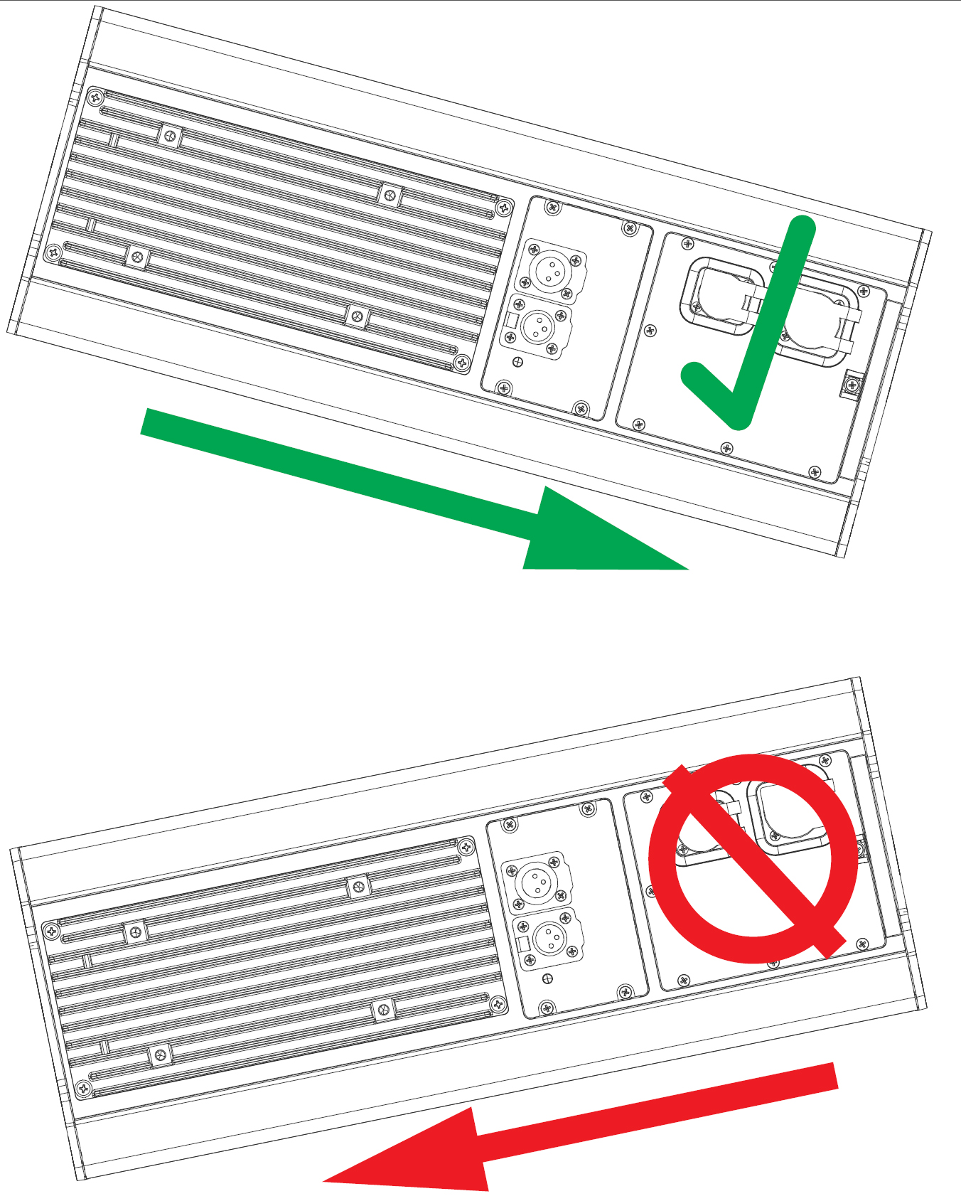
When mounting the loudspeaker, ensure that the cables will exit from the bottom of the loudspeaker (vertical orientation) or right side of the loudspeaker (horizontal orientation). There is only one permissible vertical orientation, shown in the first figure below, and one permissible horizontal orientation, as shown in the second figure below.
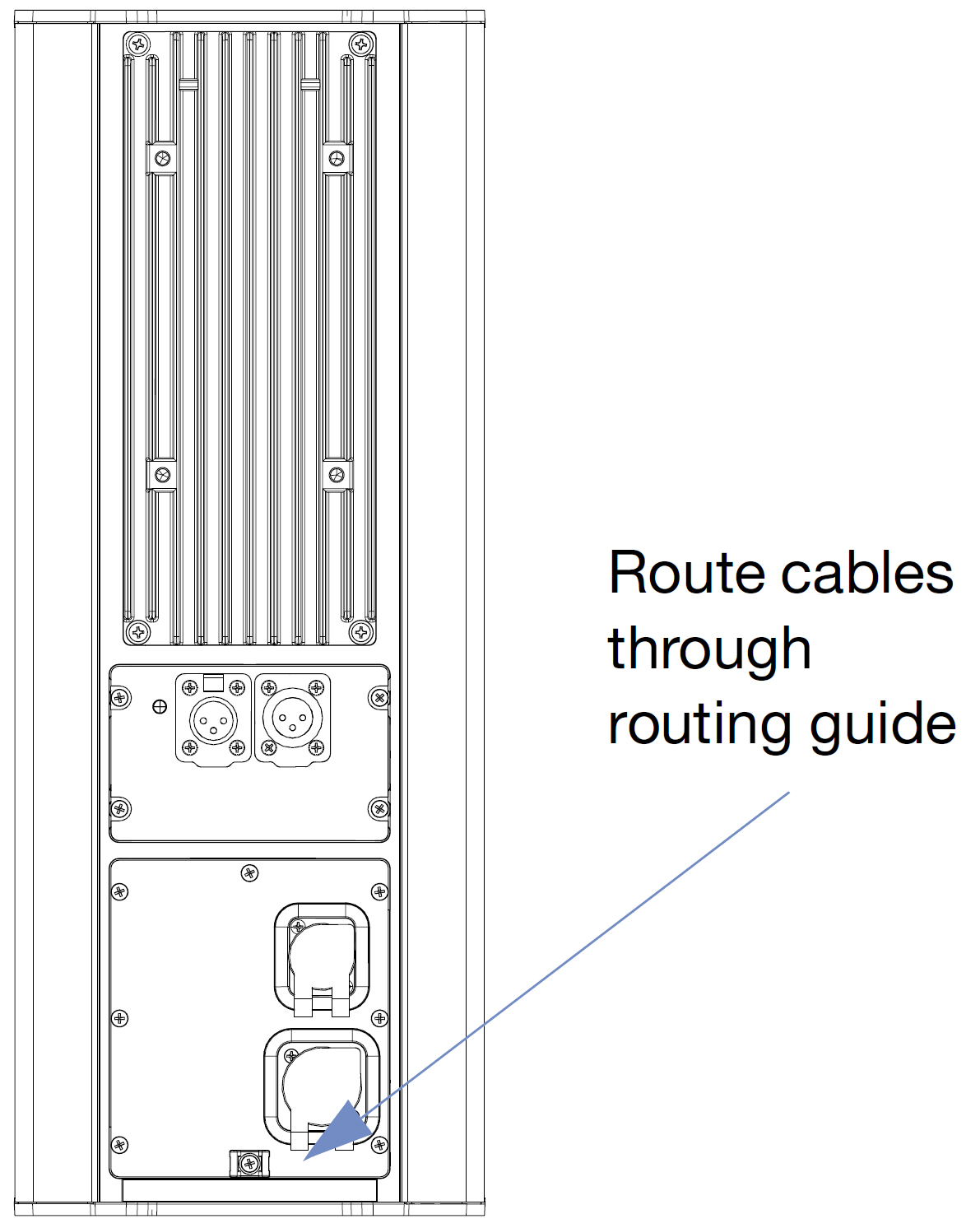
Only Permissible Vertical Orientation
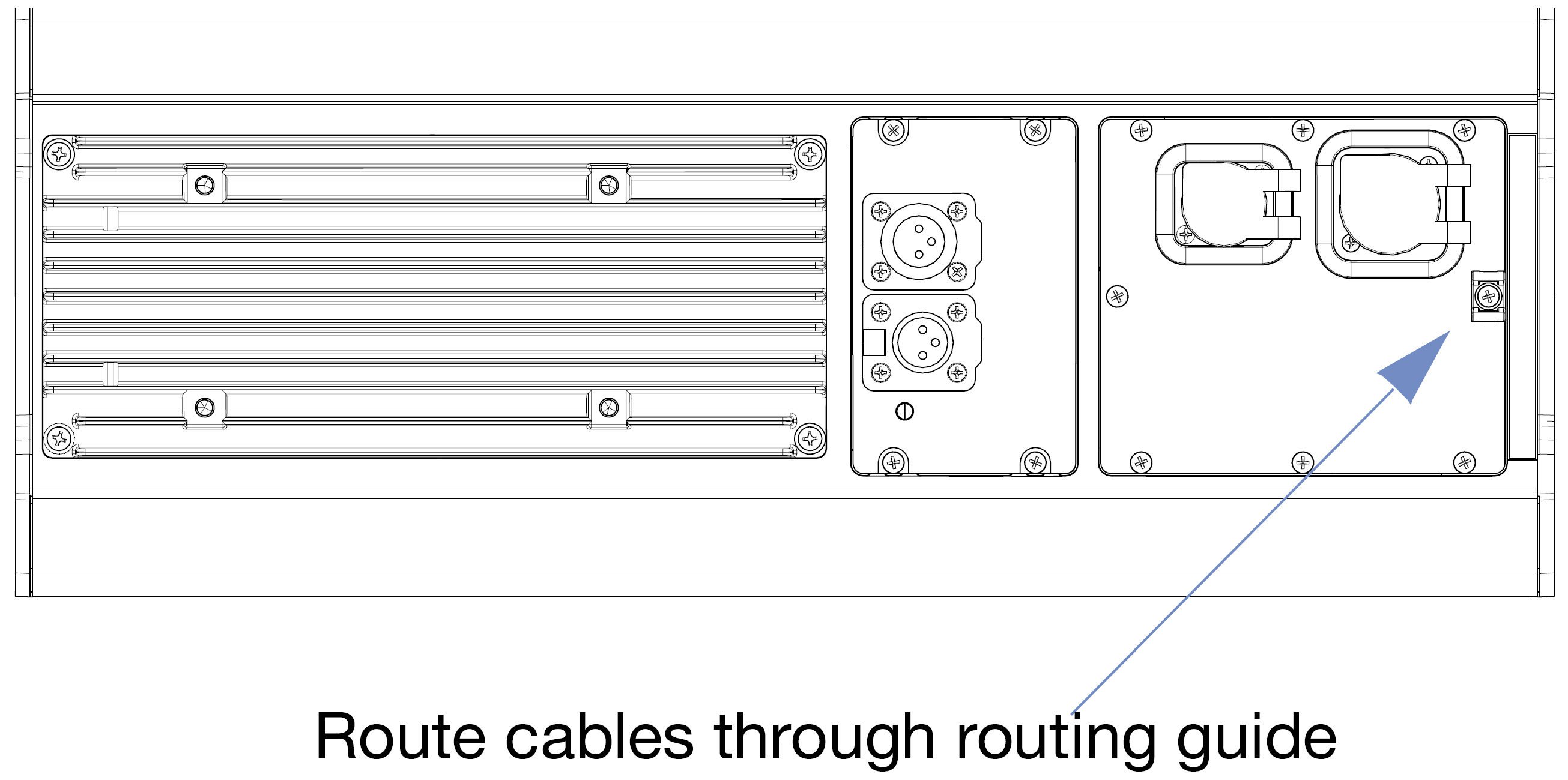
Only Permissible Horizontal Orientation
Downtilt and Uptilt
Caution
The weather-protected ULTRA-X20/22/23 loudspeaker must be mounted with a 0° tilt, or preferably with a slight downtilt with the cables exiting from the bottom. This angle shields the driver from the elements and does not allow water to accumulate in the cabinet. Do not tilt the cabinet up, as the drivers and cabinet might accumulate water.
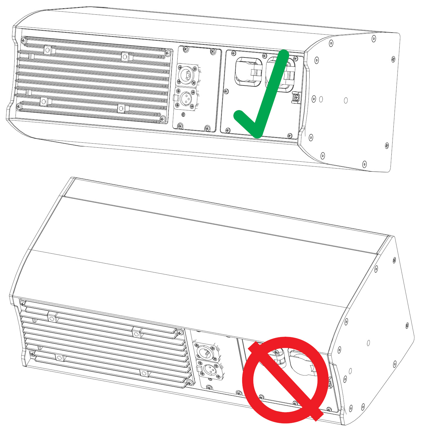
Downtilt Permissible (top); Uptilt NOT Permissible (bottom)
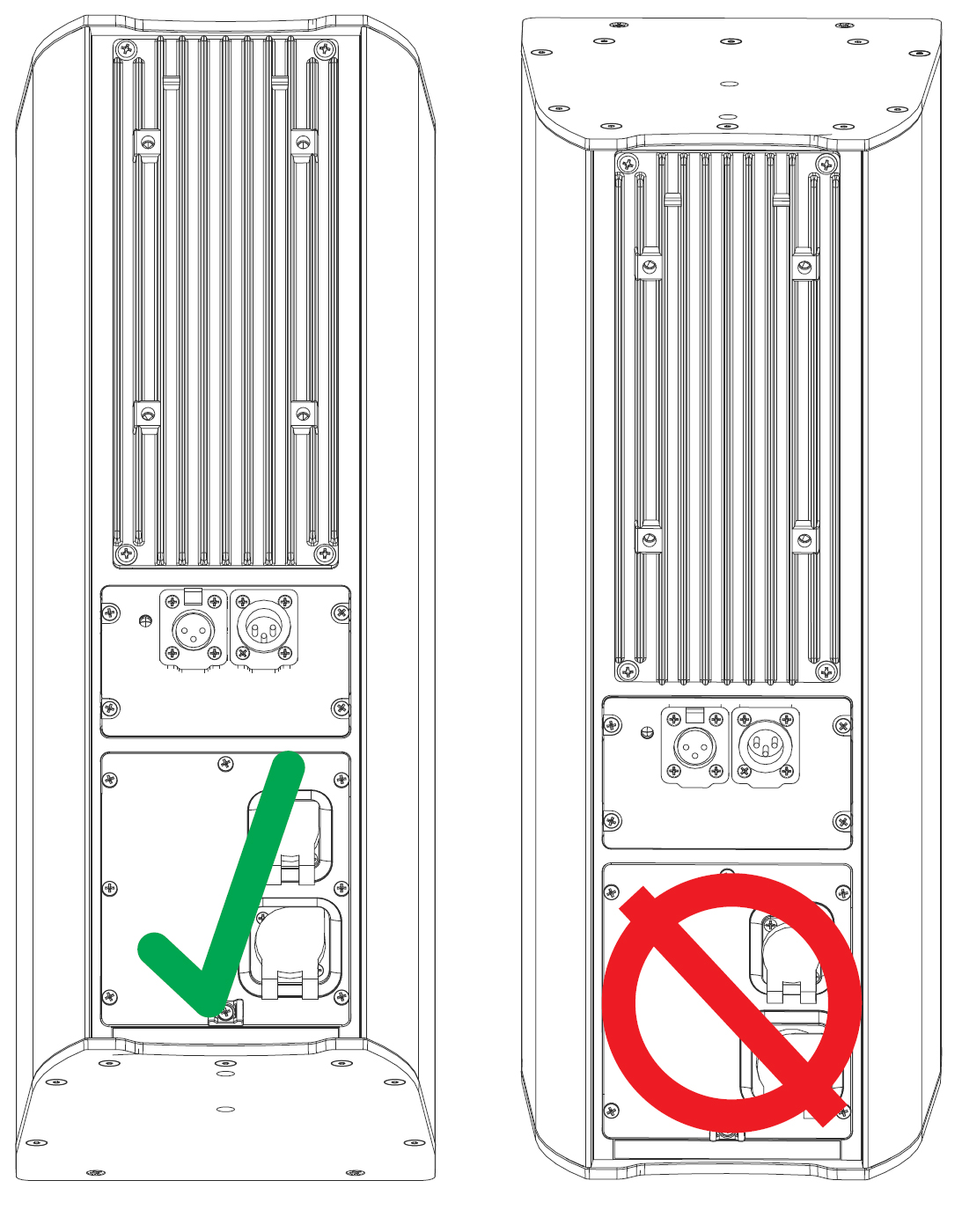
Downtilt Permissible (left); Uptilt NOT Permissible (right)
Horizontal Tilt
Caution
If tilting the loudspeaker from 0° horizontal, ensure that the horizontal tilt leaves the port below the electronics, so that water does not enter from the port and accumulate in the cabinet ([→ _bookmark98]Figure 54).
Horizontal Tilt-Away from Electronics Permissible (top); Horizontal Tilt-Toward Electronics NOT Permissible (bottom)
PowerCon TRUE1 TOP Connection
To connect a PowerCON cable to the chassis, match the one wider notch on the cable connector to the corresponding one larger guide slot on the chassis.
Caution
When inserting a PowerCON connector into the chassis, use a maximum force of 1 Newton (0.225 lb).
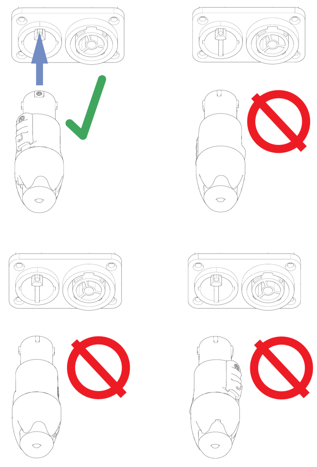
Proper PowerCON Connector Orientation
Caution
Incorrect insertion may cause electrical contact misalignment resulting in equipment malfunction and/or personal injury.
After inserting properly as indicated in the figure above (top left), and the figure below, twist the cable connector clockwise to lock.
Note
The proper twist-lock is achieved when the silver-colored tab is in the position shown in the last figure below, and an audible click is heard.
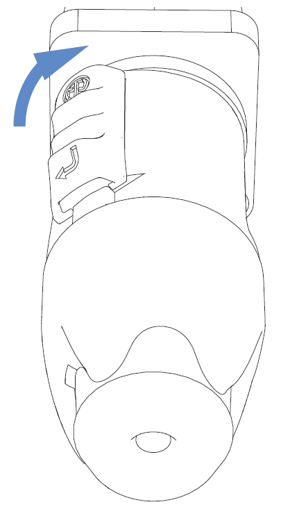
Rotate the Connector to Lock
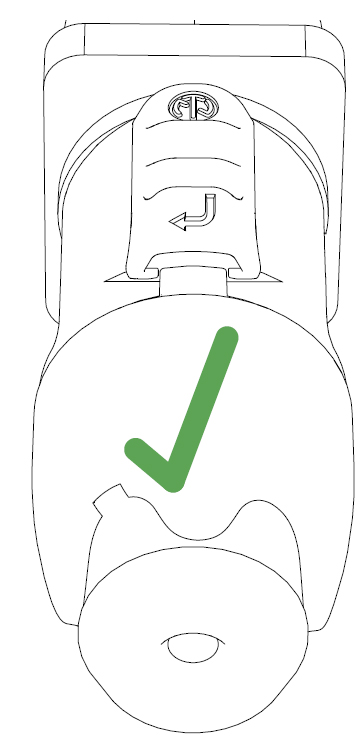
Locked Connector Position