Operating Instructions — LINA
Very compact linear line array loudspeaker
The LINA very compact linear line array loudspeaker, shown in the figure below, excels in array performance while providing exceptional high-frequency headroom, phase coherence, and consistent coverage. Its lightweight and small size are ideal for venues that require a low-profile, high-power, curvilinear array system with exceptional fidelity, such as small theaters, theme parks, houses of worship, and audio-visual systems.
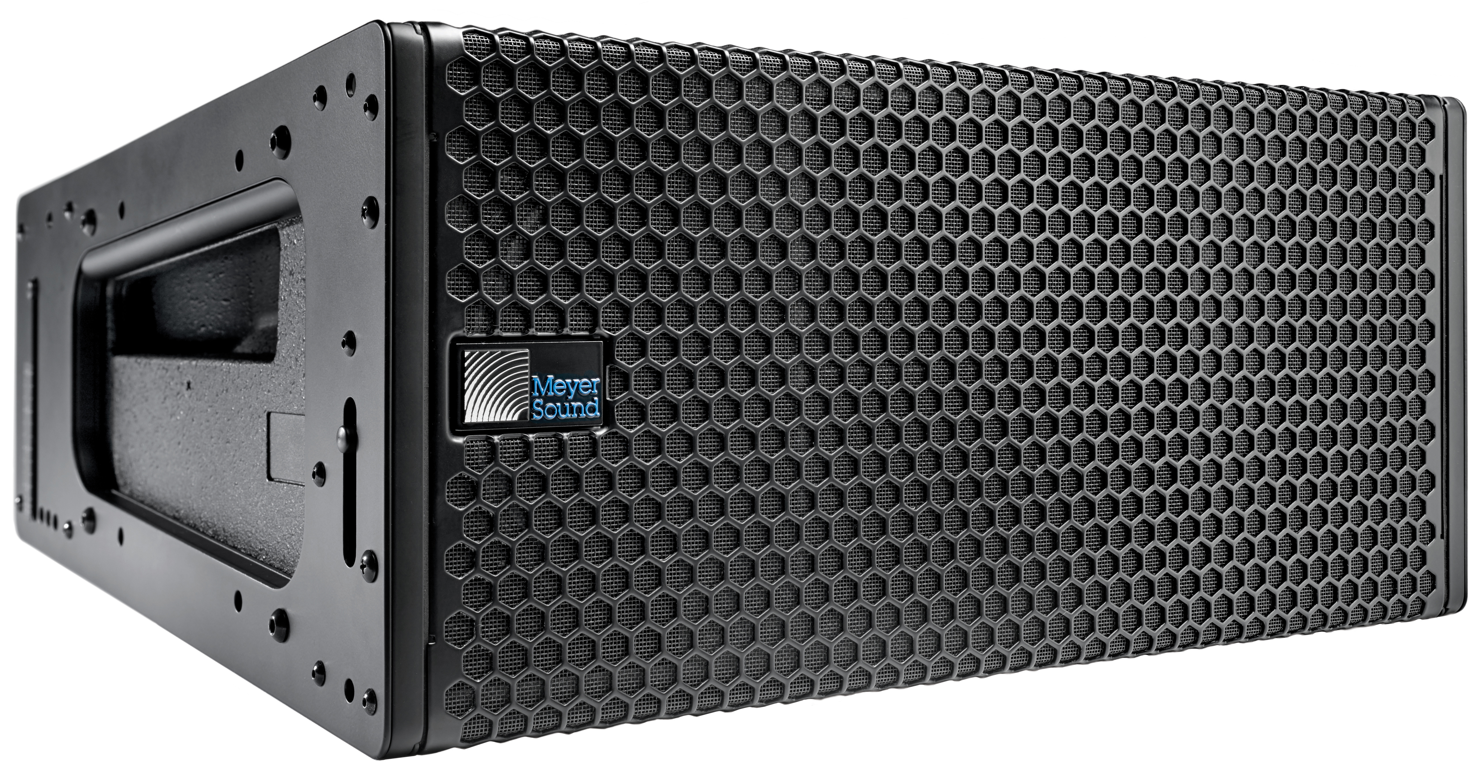
LINA Compact Linear Line Array Loudspeaker
LINA is also ideally suited for front-fill and under-balcony applications that must attain precise high-frequency vertical coverage with a single loudspeaker or short array. In addition to standalone implementations, LINA can also be used in a LEOPARD system as a supplemental fill loudspeaker.
LINA evolved from the highly successful MINA loudspeaker. Meyer Sound optimized LINA using the state-of-the-art technology that made the LEO™ family an award-winning product line: self-powered design, linear response, and precise directional control. Like LEOPARD, LINA loudspeakers offer Native Mode, which yields excellent system performance right out of the box with minimal external processing.
LINA features an innovative, highly efficient class D amplifier that reproduces any sound source with linearity over a wide dynamic range, from speech and classical music to rock and EDM. LINA faithfully reproduces audio with tremendous power, superior intelligibility, and extremely low distortion.
For low-frequency extension, LINA pairs with Meyer Sound’s 750-LFC low-frequency control element, which can be flown in a LINA array without transition hardware. Like LINA, the 750-LFC is efficient and versatile, with an excellent power-to-size ratio. Applications that require more low-frequency headroom can use Meyer Sound’s 900-LFC, which also integrates with LINA systems.
LINA includes Meyer Sound’s QuickFly® rigging with cap- tive GuideALinks™, which are compatible with MINA (same external dimensions) and can create splay angles from 1 to 11 degrees. Rigging options are shared with MINA and include the MG-MINA/LINA/750-LFC Multipurpose Grid (shown in the first figure below), the MCF-MINA/LINA Caster Frame (shown in the second figure below), the MYA-MINA/LINA Yoke, and the MUB-MINA/LINA U-Bracket.
Entire LINA family systems should be designed with Meyer Sound’s MAPP prediction software, which effectively predicts system SPL and coverage requirements. Using the Meyer Sound MDM-832 distribution module to route AC power, balanced audio, and RMS™ to multiple LINA loudspeakers makes configuring a system much easier and faster.
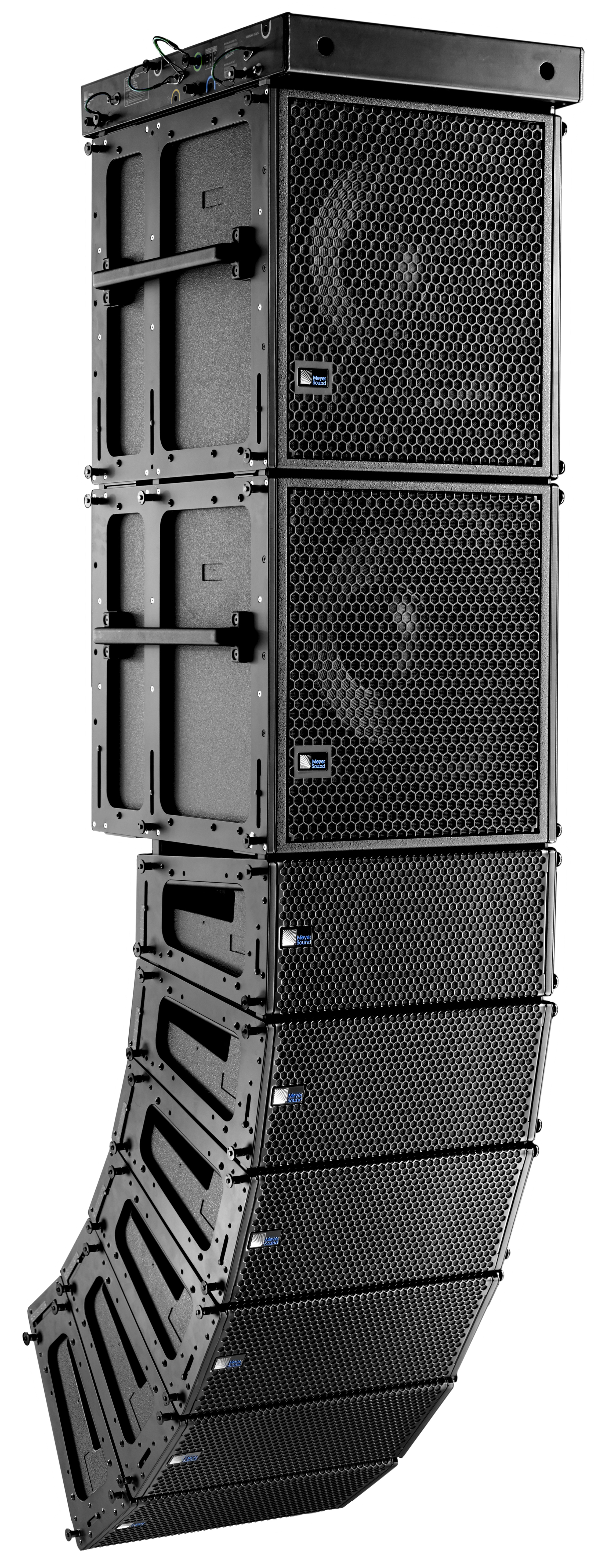
MG-MINA/LINA/750-LFC Multipurpose Grid with Mixed Array
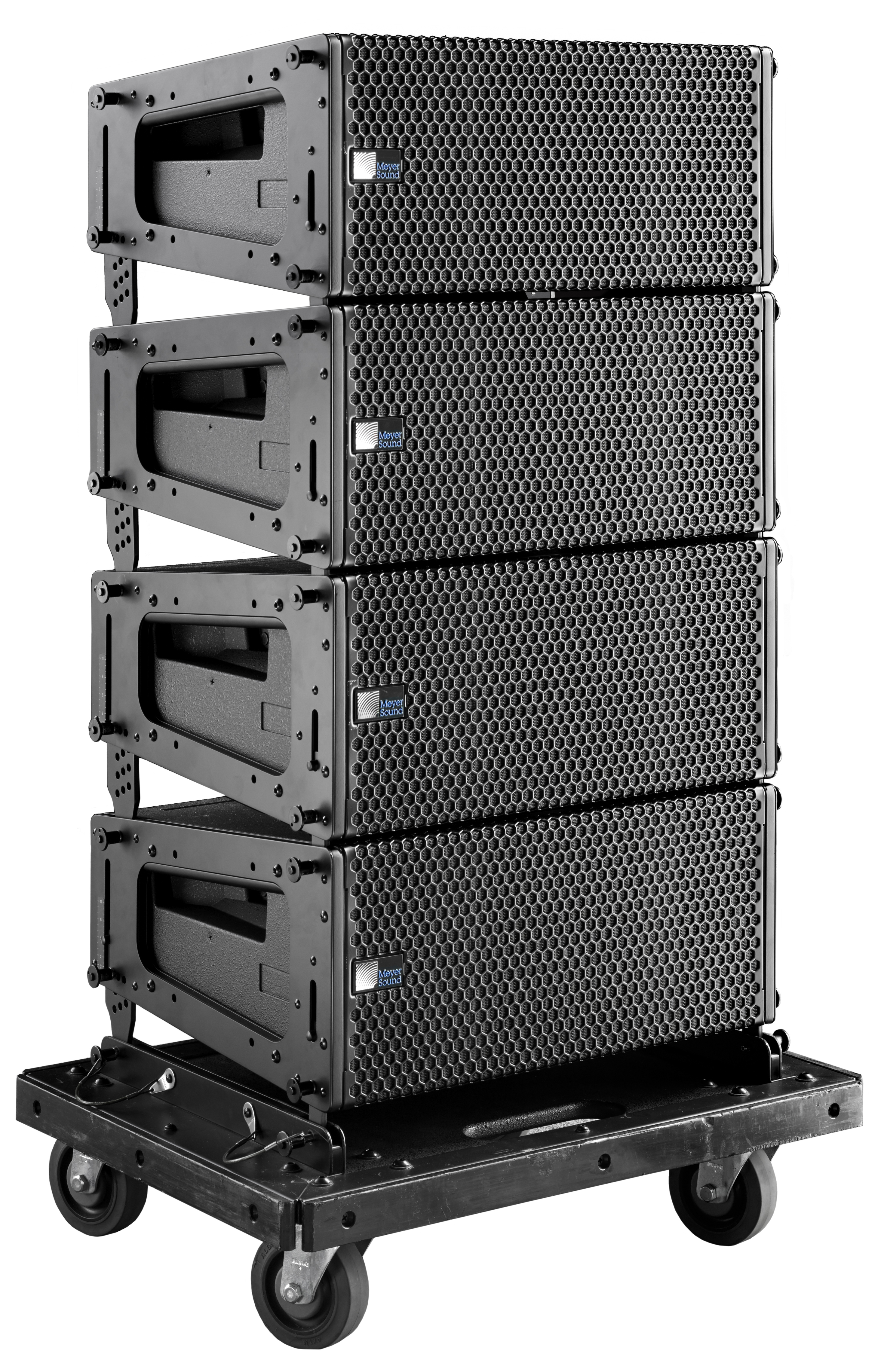
MCF-MINA/LINA Caster Frame with LINA Stack
Native Mode
LINA and 750-LFC loudspeakers are optimized for use in certain flown and groundstacked configurations without any array compensation or other signal processing. This capability, called Native mode, allows LINA/750-LFC systems to be deployed quickly with excellent results, without equalization, tuning, or use of presets.
To use LINA and 750-LFC loudspeakers in Native mode, send an identical, unmodified signal to each element in the array. Looping the same unprocessed source signal through all array elements is the simplest approach.
The following coplanar configurations can be used in Native mode (without any signal processing):
Flown mixed arrays of LINAs and 750-LFCs

Flown Mixed Array
Flown separate arrays of LINAs and 750-LFCs
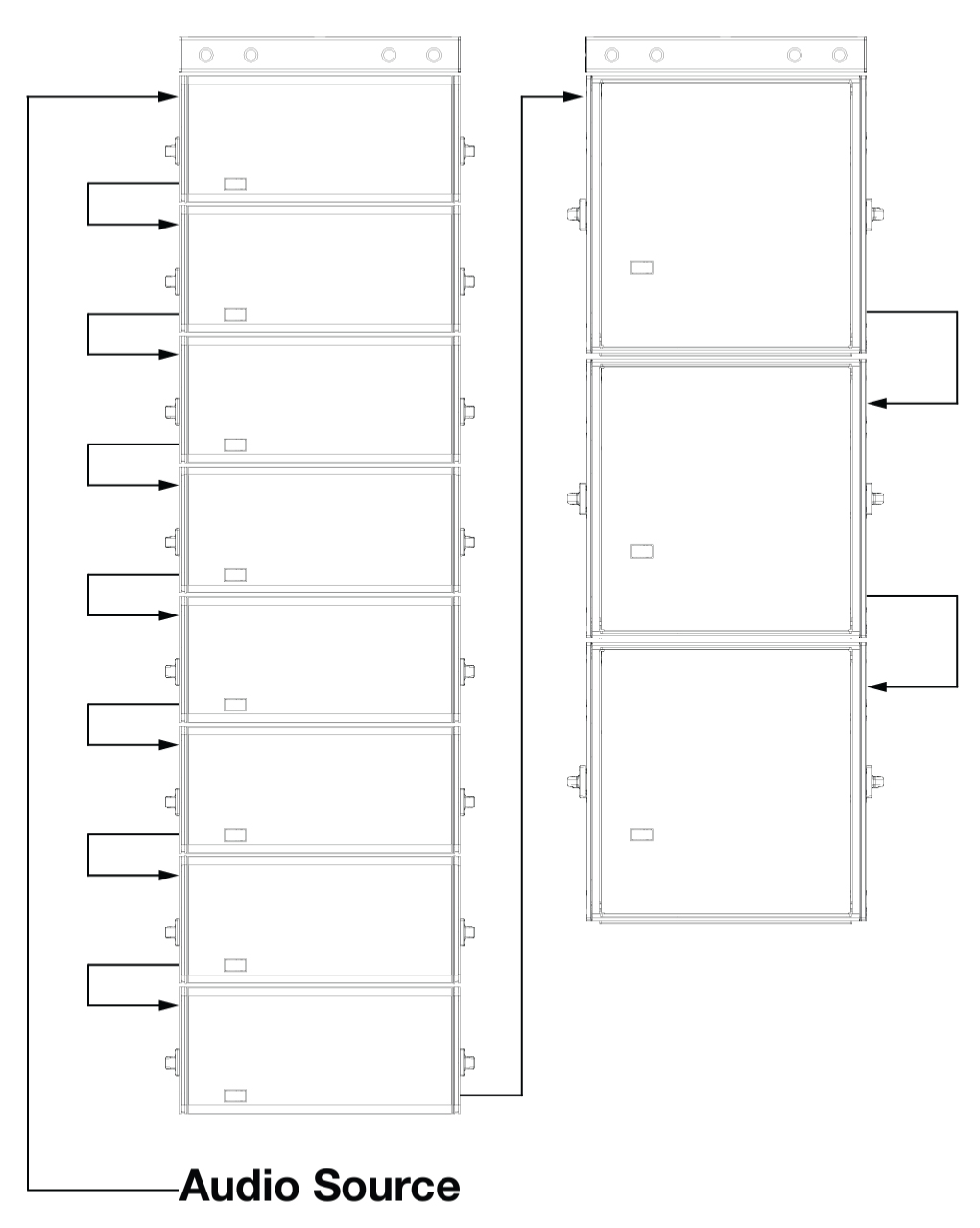
Flown Separate Arrays
Mixed groundstacks of LINAs and 750-LFCs
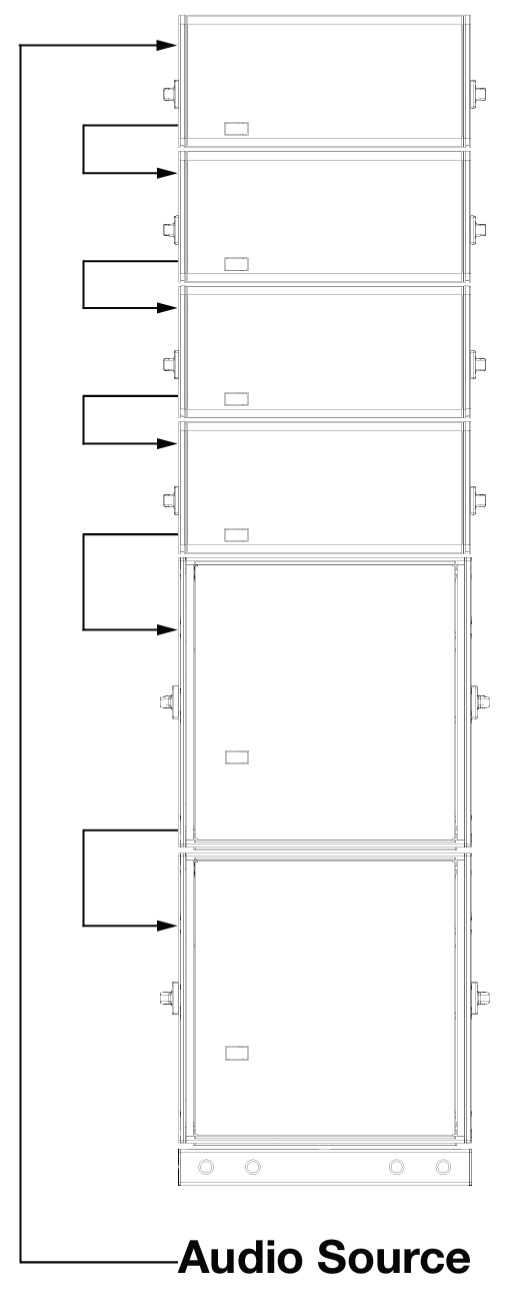
Mixed Groundstack
Note
Native mode should not be used with more advanced configurations, such as those where 750-LFCs and LINAs are not coplanar, or those requiring delay offsets to align subsystems or to create directional low-frequency control. These systems require additional processing.
For Native mode to work properly, the source signal must be correctly configured with the appropriate gain structure.
Caution
Make sure that all cabling for looped loudspeakers is wired correctly (Pin 1 to Pin 1, Pin 2 to Pin 2, and so forth) to prevent the polarity from being reversed. If one or more loudspeakers in a system have reversed polarity, frequency response and coverage will be significantly degraded.
Power Requirements
LINA combines advanced loudspeaker technology with equally advanced power capabilities. Understanding power distribution, voltage and current requirements, and electrical safety guidelines are critical for the safe operation of LINA.
AC Power Distribution
All components in an audio system (self-powered loudspeakers, mixing consoles, and processors) must be properly connected to an AC power distribution system, ensuring that AC line polarity is preserved and that all grounding points are connected to a single node or common point using the same cable gauge (or larger) as the neutral and line cables.
Caution
Make sure the voltage received by LINA remains within its 90–264 V AC operating range. In addition, the ground line must always be used for safety reasons and the line-to-ground voltage should never exceed 250 V AC (typically 120 V AC from line to ground).
Before applying AC power to any Meyer Sound self-powered loudspeaker, make sure that the voltage potential difference between the neutral and earth-ground lines is less than 5 V AC when using single-phase AC wiring.
Note
Improper grounding of connections between loudspeakers and the rest of the audio system may produce noise or hum, or cause serious damage to the input and output stages of the system’s electronic components.
120 V AC, 3-Phase Wye System (Single Line) Line-Neutral-Earth/Ground
The figure below illustrates a basic 120 V AC, 3-phase Wye distribution system with the loudspeaker load distributed across all three phases, with each loudspeaker connected to a single line and common neutral and earth/ground lines. This system delivers 120 V AC to each loudspeaker
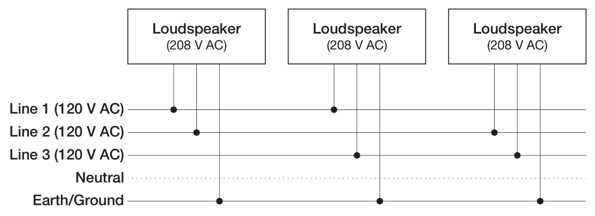
120 V AC, 3-Phase Wye System (Single Line to Loudspeakers)
120 V AC, 3-Phase Wye System (Two Lines) Line-Line-Earth/Ground
The figure below illustrates a 120 V AC, 3-phase Wye distribution system with each loudspeaker connected to two lines and a common earth/ground line. This configuration is possible because LINA tolerates elevated voltages from the ground line and does not require a neutral line. This system delivers 208 V AC to each loudspeaker.

120 V AC, 3-Phase Wye System (Two Lines to Loudspeakers)
Tip
The 120 V AC, 3-phase Wye system with two lines is recommended because it allows loudspeakers to draw less current than with single-line systems, thereby reducing voltage drop due to cable resistance. It also excludes the potential of varying ground to neutral voltages producing an audible hum.
230 V AC, 3-Phase Wye System (Single Line) Line-Neutral-Earth/Ground
The figure below illustrates a basic 230 V AC, 3-phase Wye distribution system with the loudspeaker load distributed across all three phases, with each loudspeaker connected to a single line and common neutral and earth/ground lines. This system delivers 230 V AC to each loudspeaker.
 |
230 V AC, 3-Phase Wye System (Single Line to Loudspeakers)
Caution
For 230 V AC, 3-phase Wye systems, never connect two lines to the AC input of Amie, as the resulting voltage would exceed the upper voltage limit (275 V AC) and will damage the loudspeaker.
AC Connectors
The LINA user panel includes two powerCON 20 connectors, as shown in the figure below, one for AC Input (blue) and one for AC Loop Output (gray).
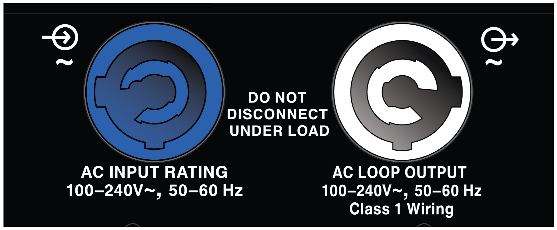
AC Input (Left) and AC Loop Output (Right) Connectors
AC Input (Blue)
The blue AC Input connector supplies power to LINA. The 3-conductor powerCON 20 is rated at 20 A and uses a locking connector that prevents accidental disconnections. A 10-foot AC power cable, rated at 15 A, is included with each loudspeaker. If you replace the included AC power cable, make sure to use a cable with the appropriate power plug (on the other end) for the area in which you will operate the loudspeaker. LINA requires a grounded outlet. To operate safely and effectively, it is extremely important that the entire system be properly grounded.
The AC Input connector also supplies power to any additional loudspeakers connected to the loudspeaker’s gray Loop Output connector.
Caution
When looping AC power for loudspeakers, do not exceed the current capability of the AC Input connector (20 A) or the included AC power cable (15 A). Consider the total current draw for all loudspeakers on the circuit, including the first loudspeaker. See AC Loop Output (Gray) for more information.
AC Loop Output (Gray)
The gray AC Loop Output connector allows multiple LINAs to be looped and powered from a single power source. The 3-conductor powerCON 20 is rated at 20 A and uses a locking connector that prevents accidental disconnections. For applications that require multiple LINAs, connect the AC Loop Output of the first loudspeaker to the AC Input of the second loudspeaker, and so forth.
The maximum number of loudspeakers that can be looped from the AC Loop Output connector is determined by the voltage of the power source, the current draw of the looped loudspeakers, the circuit breaker rating, and the rating of the AC power cable connected to the first LINA loudspeaker, as shown in the table below.
Circuit Breaker/ Connector Rating | 115 V AC | 230 V AC | 100 V AC |
|---|---|---|---|
15 A / 16 A | 5 looped (6 total) | 11 looped (12 total) | 4 looped (5 total) |
20 A | 7 looped (8 total) | 16 looped (17 total) | 6 looped (7 total) |
Note
Current draw for LINA is dynamic and fluctuates as operating levels change. The indicated number of loudspeakers that can be looped assumes that operating levels are normal and not such that loudspeakers are constantly limiting.
LINA ships with a gray powerCON 20 cable mount connector, rated at 20 A, for assembling AC looping cables. Assembled AC looping cables are also available from Meyer Sound.
Caution
When looping AC power for loudspeakers, do not exceed the current capability of the AC Input connector (20 A) or the included AC power cable (15 A). Consider the total current draw for all loudspeakers on the circuit, including the first loudspeaker, as shown in the table above.
Wiring AC Power Cables
LINA ships with a gray powerCON 20 cable mount connector, rated at 20 A, for assembling AC looping cables, shown in the figure below. The pins on the powerCON 20 cable mount connector are labeled as follows:
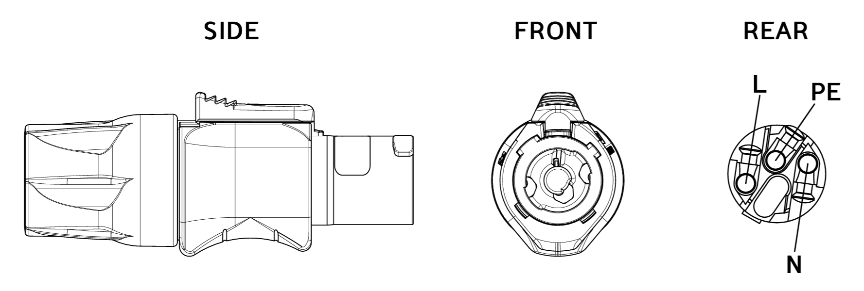 |
powerCON 20 Cable Mount Connector
How AC power cables are wired is determined by the type of AC power distribution system used (see AC Power Distribution). When wiring AC power cables for single-line systems, use one of the wiring schemes described in the table below and illustrated in the figure above:
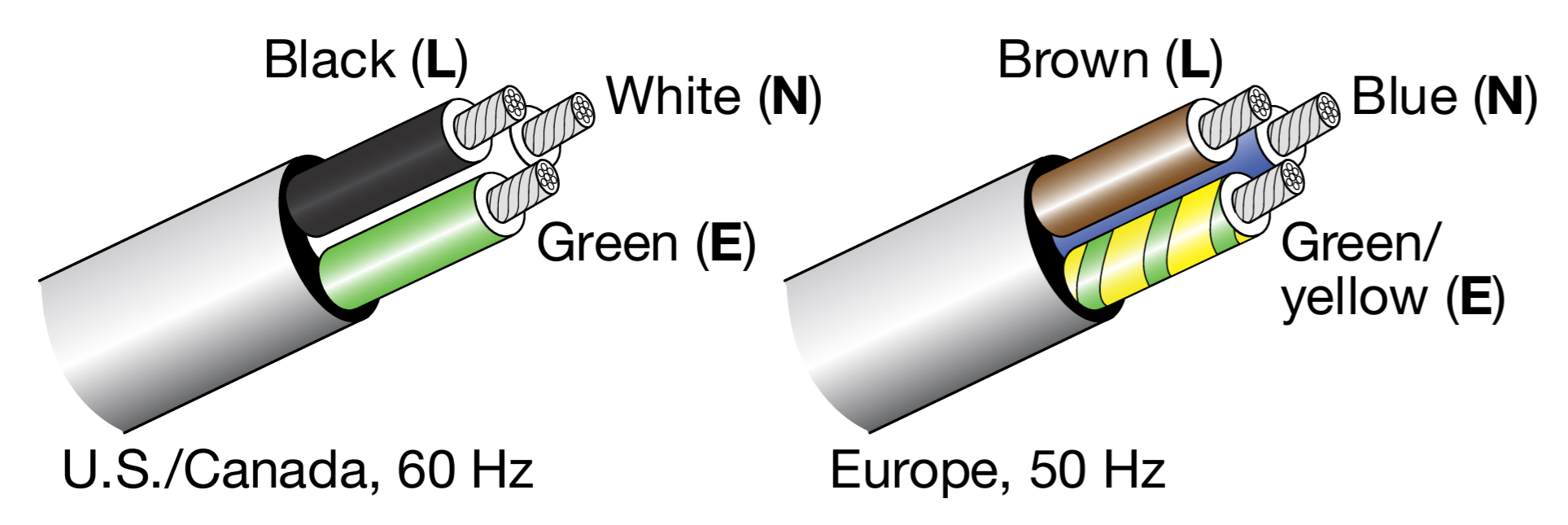
AC Wiring Scheme, illustrated
Wire Color | Attach to the Following Terminal | |
|---|---|---|
U.S. / Canada 60 Hz | European 50 Hz | |
Black | Brown | Hot or live (L |
White | Blue | Neutral (N) |
Green | Green or Yellow | Protective earth / ground (E or PE) |
Caution
When wiring AC power cables and distribution systems, it is important to preserve AC line polarity and connect the earth ground on both ends of the cable. LINA requires a grounded connection. Always use a grounded outlet and plug. It is extremely important that the system be properly grounded to operate safely and properly. Do not ground-lift the AC cable.
Voltage Requirements
LINA operates as intended when receiving AC voltage within the following range:
90–264 V AC, 50–60 Hz
If the voltage drops below 90 V, the loudspeaker uses stored power to continue operating temporarily; the loudspeaker powers off if the voltage does not return to its operating range.
If the voltage rises above 275 V, the power supply could become damaged.
Caution
The power source for LINA should always operate within the required operating range, at least a few volts from the upper and lower limits. This ensures that AC voltage variations from the service entry—or peak voltage drops due to cable runs—will not cause the loudspeaker’s amplifier to cycle on and off or cause damage to the power supply.
Current Requirements
Current draw for loudspeakers is dynamic and fluctuates as operating levels change. Because different cables and circuit breakers heat up at varying rates, it is important to understand the following types of current ratings and how they affect circuit breaker and cable specifications.
Idle Current — The maximum rms current during idle periods.
Maximum Long-Term Continuous Current — The maximum rms current during a period of at least 10 seconds. The maximum long-term continuous current is used to calculate temperature increases for cables to ensure that the size and gauge of the cables conform to electrical code standards. The current rating is also used to select appropriately rated, slow-reacting thermal breakers, which are recommended for loudspeaker power distribution. In addition, the maximum long-term continuous current can be used to calculate the AC looping capability for LEOPARD loudspeakers.
Burst Current — The maximum rms current during a period of around 1 second. The burst current is used as a rating for magnetic breakers. It is also used for calcuating the peak voltage drop in long AC cable runs according to the following formula:
V pk (drop) = I pk x R (cable total)
Maximum Instantaneous Peak Current — A rating for fast-reacting magnetic breakers.
Use the information provided in the table below as a guide for selecting the gauge of cables and the circuit breaker ratings for the system’s operating voltage.
Current Draw | 115 V AC | 230 V AC | 100 V AC |
|---|---|---|---|
Idle | 0.25 A rms | 0.25 A rms | 0.29 A rms |
Maximum Long- Term Continuous | 2.3A rms | 1.16 A rms | 2.8 A rms |
Burst | 3.9 A rms | 1.7 A rms | 4.5 A rms |
Maximum Instantaneous Peak | 8.8 A peak | 4.0 A peak | 9.2 A peak |
The minimum electrical service amperage required by a loudspeaker system is the sum of the maximum long-term continuous current for all loudspeakers. An additional 30 percent above the combined Maximum Long-Term Continuous amperages is recommended to prevent peak voltage drops at the service entry.
Note
For best performance, the AC cable voltage drop should not exceed 10 V (10 percent at 115 V and 5 percent at 230 V). This ensures that the AC voltage variations from the service entry—or peak voltage drops due to longer cable runs—do not cause the amplifier to cycle on and off.
Intelligent AC Power Supply
LINA’s Intelligent AC™ power supply automatically selects the correct operating voltage (allowing the loudspeaker to be used internationally without manually setting voltage switches), eliminates high inrush currents with soft-start power up, suppresses high-voltage transients up to several kilovolts, filters common mode and differential mode radio frequencies (EMI), and sustains operation temporarily during low-voltage periods
Powering on LINA
When powering on LINA, the following startup events take place over several seconds.
Audio output is muted.
Voltage is detected and the power supply mode is automatically adjusted as necessary.
The power supply ramps up.
On the user panel, the Active/Status LED flashes multiple colors successively.
The Active/Status LED turns solid green, indicating the loudspeaker is unmuted and ready to output audio.
Caution
If the Active/Status LED does not turn solid green, or LINA does not output audio after 10 seconds, remove AC power immediately and verify that the voltage is within the required range. If the problem persists, contact Meyer Sound Technical Support.
Electrical Safety Guidelines
Make sure to observe the following important electrical and safety guidelines.
The powerCON 20 connector should not be engaged or disengaged when under load or energized. Either de-energize-energize or disconnect the other end of the cable.
LINA requires a grounded outlet. Always use a grounded outlet and plug.

Do not use a ground-lifting adapter or cut the AC cable ground pin.

Do not exceed the current capability of the 20 A AC Input connector for the loudspeaker. When looping loudspeakers, consider the total current draw for all loudspeakers on the circuit, including the first loudspeaker.
Make sure the AC power cable for the loudspeaker has the appropriate power plug (on the other end) for the area in which you will operate the loudspeaker. In addition, the AC power cable must be rated for the total current draw of all loudspeakers looped from the power source.
Do not operate the loudspeaker if the power cable is frayed or broken.
Keep all liquids away from LINA loudspeakers to avoid hazards from electrical shock.
Amplification and Audio Connectors
LINA’s drivers are powered by a proprietary 3-channel, open-loop, class D amplifier. The audio signal is processed with electronic crossover, and correction filters for flat phase and frequency responses, and by driver protection circuitry. Each channel has peak and rms limiters that prevent driver over-excursion and regulate voice coil temperatures.
The LINA user panel, shown in the figure below, includes Input and Loop output connectors for audio, Limit and On/Status LEDs, and RMS connectors and controls (see RMS Remote Monitoring System).
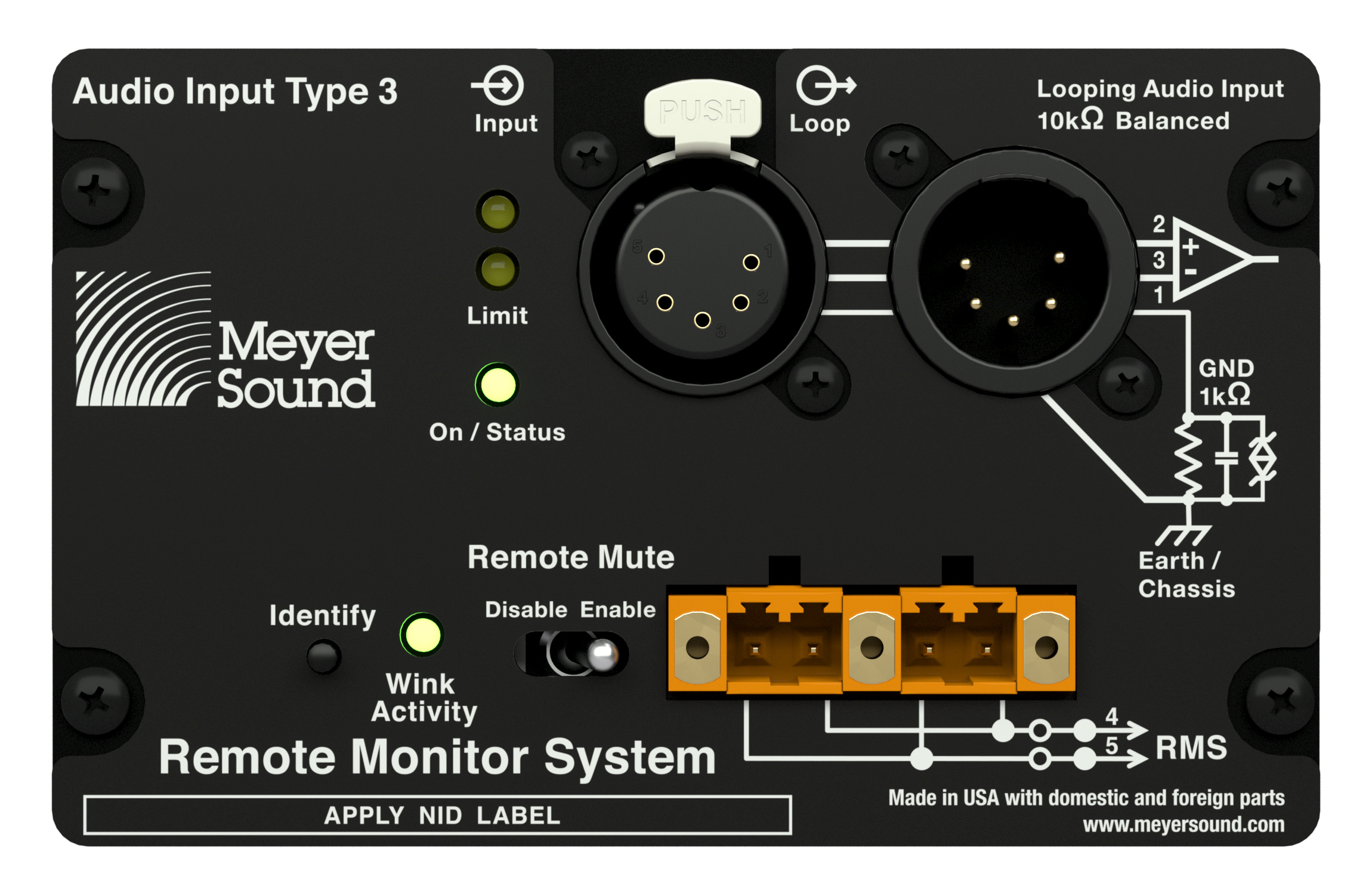
LINA User Panel
Audio Connectors
LINA is available with XLR 5-pin or 3-pin connectors for audio Input and audio Loop output, as shown in the figures below. XLR 5-pin connectors accommodate both balanced audio and RMS signals.
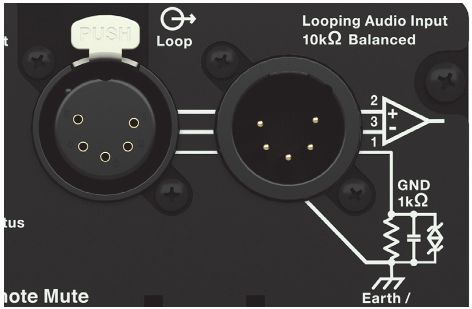
XLR 5-Pin Audio Connectors, Input and Loop Output
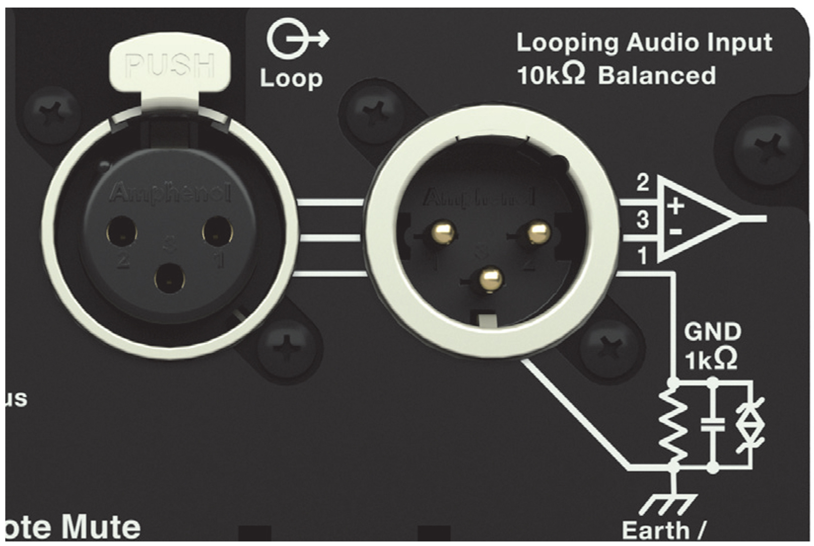
XLR 3-Pin Audio Connectors, Input and Loop Output
Audio Input (XLR 3-Pin or 5-Pin Female)
The XLR 3-pin or 5-pin female Input connector accepts balanced audio signals with an input impedance of 10 kΩ. The connector uses the following wiring scheme:
Pin 1 — 1 kΩ to chassis and earth ground (ESD clamped)
Pin 2 — Signal (+)
Pin 3 — Signal (–)
Pin 4 — RMS (polarity insensitive)
Pin 5 — RMS (polarity insensitive)
Case — Earth (AC) ground and chassis
Note
Pins 4 and 5 (RMS) are included only with XLR 5-pin connectors.
Pins 2 and 3 carry the input as a differential signal. Pin 1 is connected to earth through a 1 kΩ, 1000 pF, 15 V clamped network. This circuitry provides virtual ground lift for audio frequencies while allowing unwanted signals to bleed to ground. Make sure to use balanced XLR audio cables with pins 1–3 connected on both ends. Telescopic grounding is not recommended and shorting an input connector pin to the case may cause a ground loop, resulting in hum.
Tip
If the loudspeaker produces unwanted noise or hiss, disconnect its input cable. If the noise stops, there is most likely nothing wrong with the loudspeaker. To locate the source of the noise, check the source audio, AC power, and electrical ground.
Audio Loop Output (XLR 3-Pin or 5-Pin Male)
The XLR 3-pin or 5-pin male Loop output connector allows multiple loudspeakers to be looped from a single audio source. The Loop output connector uses the same wiring scheme as the Input connector (see Audio Input (XLR 3-Pin or 5-Pin Female)). For applications that require multiple LINAs, connect the Loop output of the first loudspeaker to the Input of the second loudspeaker, and so forth.
Note
The Loop output connector is wired in parallel to the Input connector and transmits the unbuffered source signal even when the loudspeaker is powered off.
Calculating Load Impedance for Looped Audio Signals
To avoid distortion when looping multiple loudspeakers, make sure the source device can drive the total load impedance of the looped loudspeakers. In addition, the source device must be capable of delivering approximately 20 dBV (10 V rms into 600 Ω) to yield the maximum SPL over the operating bandwidth of the loudspeakers.
To calculate the load impedance for the looped loudspeakers, divide 10 kΩ (the input impedance for a single loudspeaker) by the number of looped loudspeakers. For example, the load impedance for 10 LINAs is 1000 Ω (10 kΩ/ 10). To drive this number of looped loudspeakers, the source device should have an output impedance of 100 Ω or less. This same rule applies when looping LINAs with other Meyer Sound selfpowered loudspeakers.
Note
Most source devices are capable of driving loads no less than 10 times their output impedance.
Tip
Audio outputs from Meyer Sound’s loudspeaker GALAXY Network Platform have an output impedance of 50 ohms. Each output can drive up to 20 Meyer Sound (10 kΩ) loudspeakers without distortion
Caution
Make sure that all cabling for looped loudspeakers is wired correctly (Pin 1 to Pin 1, Pin 2 to Pin 2, and so forth) to prevent the polarity from being reversed. If one or more loudspeakers in a system have reversed polarity, frequency response and coverage will be significantly degraded.
TruPower Limiting
LINA employs Meyer Sound’s advanced TruPower® limiting. Conventional limiters assume a constant driver impedance and set the limiting threshold by measuring voltage alone. This method is inaccurate because driver impedances change as frequency content in the source material changes and as thermal values for the loudspeaker’s voice coil and magnet vary. Consequently, conventional limiters often begin limiting prematurely, which reduces system headroom and dynamic range.
In contrast, TruPower limiting anticipates varying driver impedances by measuring both current and voltage to compute the actual power dissipation in the voice coil. This approach improves performance, both before and during limiting, by allowing the driver to produce the maximum SPL across its entire frequency range, while also retaining signal peaks. TruPower limiting also eliminates power compression at high levels over lengthy periods, which helps regulate voice coil temperatures, thereby extending the life of the driver.
HF and LF Limit LEDs
The low- and high-frequency drivers for LINA are powered by separate amplifier channels, which have limiters. Limiting activity is indicated with two Limit LEDs on the user panel. The Limit LEDs, shown in the figure below, indicate limiting for the high-frequency channel and/or the low-frequency channels.
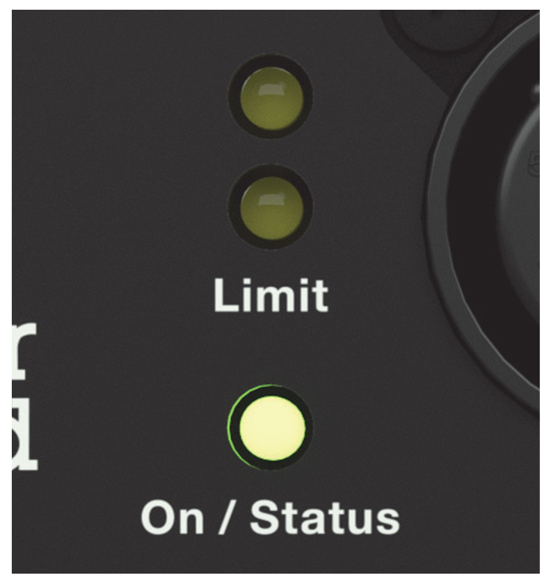 |
LINA Limit LEDs
When engaged, the limiters not only protect the drivers but also prevent signal peaks from causing excessive distortion in the amplifier channels, thereby preserving headroom and maintaining smooth frequency response at high levels. When levels return to normal, below the limiter thresholds, limiting ceases.
LINA performs within its acoustical specifications at normal temperatures when the Limit LEDs are unlit, or when the LEDs are lit for 2 seconds or less and then turn off for at least 1 second. If the LEDs remain lit for longer than 3 seconds, the loudspeaker enters hard limiting where:
Increases to the input level have no effect
Distortion increases due to clipping
Drivers are subjected to excessive heat and excursion, thereby compromising their lifespan
Caution
The Limit LEDs indicate when a safe, optimum level is exceeded. If a LINA loudspeaker system begins to limit before reaching the desired SPL, consider adding more units to the system.
Amplifier Cooling System
LINA is convection cooled. The amplifier’s heat sink provides natural convection cooling from the air flowing near its fins.
Caution
To keep LINA from overheating, allow at least 6 in behind the loudspeaker for proper ventilation.
LINA’s heat sink can reach temperatures up to 80° C (176° F) during extreme operation. Wait 15 minutes for the unit to cool before touching.
Active/Status LED
During normal operation, when LINA is powered on, the Active/Status LED is solid green. If the loudspeaker encounters a hardware fault, or the unit begins to overheat, the LED flashes red. In some instances, the loudspeaker will continue to output audio while the LED flashes red, though with a reduction in the limiter threshold and acoustic output to protect the loudspeaker.
If a loudspeaker is overheating (for RMS-equipped loudspeakers, you can verify this in Compass RMS), a reduction in SPL may be necessary. If, after a reduction in SPL and an approximate cooling period, the Active/Status LED continues to flash red (does not return to solid green), contact Meyer Sound Technical Support.
If the Active/Status LED flashes red and the loudspeaker does not output audio, contact Meyer Sound Technical Support immediately.
Caution
If a LINA loudspeaker system consistently overheats before reaching the desired SPL, consider adding more units to the system.
Note
During startup, the Active/Status LED flashes multiple colors successively. For more information about the power on sequence, see “Intelligent AC Power Supply” on page 16.
Tip
When LINA is connected to an RMS network, the Compass RMS software provides additional feedback about the loudspeaker’s hardware status and operating temperature. For more information, see [→ _bookmark67]Chapter 5, “RMS Remote Monitoring System.”
Quickfly Rigging
Important Safety Considerations
When installing Meyer Sound loudspeakers and subwoofers, the following precautions should always be observed:
All Meyer Sound products must be used in accordance with local, state, federal, and industry regulations. It is the owner’s and user’s responsibility to evaluate the reliability of any rigging method for their application. Rigging should only be carried out by experienced professionals.
Use mounting and rigging hardware that has been rated to meet or exceed the weight being hung.
Make sure to attach mounting hardware to the building’s structural components (roof truss), and not just to the wall surface.
Make sure bolts and eyebolts are tightened securely. Meyer Sound recommends using Loctite® on all threaded fasteners.
Inspect mounting and rigging hardware regularly. Immediately replace any worn or damaged components.
Rigging Options
The table below summarizes the available rigging options for LINA. For complete information on rigging hardware, including dimensions, weight, configuration, and load ratings, refer to  Assembly Guide MG-MINA/LINA/750-LFC Multipurpose Grid and Accessories - PN: 05.207.101.02 A.
Model | Weight | Features | Required Quick- Release Pins | Required Shackles |
|---|---|---|---|---|
MG-MINA/LINA/750-LFC multipurpose grid kit (PN 40.207.101.01) | 39 lb (17.7 kg) | With some restrictions, flies up to 16 LINA cabinets at a 5:1 safety factor and BGV C1 with some angle restrictions (additional load ratings are possible—use MAPP to verify load ratings); supports mixed arrays of LINAs and 750-LFCs without transition hardware; accommodates a variety of pickup configurations with four corner and 11 center pickup points; can also be used for groundstacking. | 0.25 in x 0.90 in (black button), PN 134.036, qty 8 included | 5/8-inch or 3/4-inch |
MG-MINA/LINA/750-LFC multipurpose grid kit with GLK (PN 40.207.101.02) | 39 lb (17.7 kg) | With some restrictions, flies up to 16 LINA cabinets at a 5:1 safety factor and BGV C1 with some angle restrictions (additional load ratings are possible—use MAPP to verify load ratings); supports mixed arrays of LINAs and 750-LFCs without transition hardware; accommodates a variety of pickup configurations with four corner and 11 center pickup points; can also be used for groundstacking; includes MG-MINA to 750-LFC Grid Link. | 0.25 in x 0.90 in (black button), PN 134.036, qty 8 included | 5/8-inch or 3/4-inch |
MYA-MINA/LINA Yoke kit (PN 40.207.104.01) | 12.9 lb (5.85 kg) | Suspends arrays of up to three LINA cabinets from a single point and pole-mounts up to two cabinets on top of a 750-LFC (pole-mount adapter not included). The yoke includes two bracketing options: the MPA-2 for attaching to two cabinets, and the MPA-3 for attaching to one or three cabinets. | — | — |
MUB-MINA/LINA U-Bracket kit (PN 40.207.030.01) | 5.8 lb (2.63 kg) | Mounts up to five LINA cabinets for front-fill or under- balcony coverage with up to 20 degrees of tilt. Pole- mounts up to two cabinets (pole-mount adapter not included). | — | — |
PBF-LINA pull-back frame kit (PN 40.271.080.01) | 4 lb (1.8 kg) | Attaches to bottom of LINA arrays (to the bottom cabi- net) and provides pull-back for extreme array downtilt. | 0.25 in x 0.90 in (black button), PN 134.036, qty 2 included | 1/2-inch |
MCF-MINA/LINA caster frame kit (PN 40.207.102.01) | 28 lb (12.7 kg) | Safely transports up to five LINA cabinets, making it easy to assemble and disassemble arrays in blocks of five cabinets. | 0.25 in x 0.90 in (black button), PN 134.036, qty 4 included | — |
LINA GuideALinks
Each LINA loudspeaker is equipped with four captive GuideALinks that link to adjacent units in flown and groundstacked arrays. Located at the bottom corners of the end frames, the GuideALinks extend and retract with knobs and are secured with quick-release pins, as shown in the figure below.
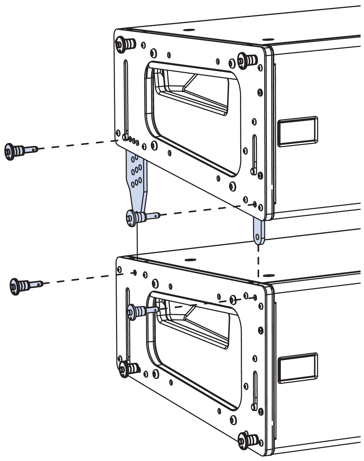
LINA GuideALinks with Quick-Release Pins
Note
When linking LINAs, two quick-release pins are required for each GuideALink: one to secure the position of the link in the top unit, and one to secure the link to the linked bottom unit. Eight (0.25 in x 0.53 in) quick-release pins are included with each LINA.
Caution
Make sure to secure the LINA GuideALinks with the included quick-release pins. GuideALink knobs are for extending and retracting the links and should not be used to support the weight of the loudspeaker (without using the pins) when fully extended.
Front GuideAlinks
The front GuideALinks, shown in the figure below, act as a pivot point between linked LINAs, with the splay angle between the units determined by the rear GuideALink positions. When stowing front GuideALinks, the knob is positioned at the top of the slot.
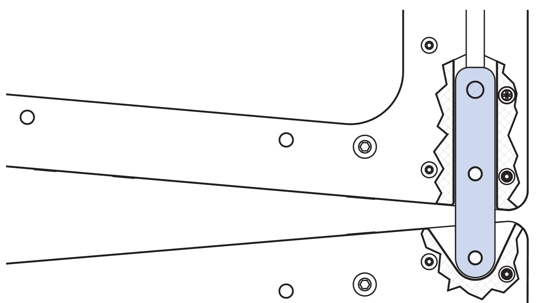
Front GuideALinks
Rear GuideALinks
The rear GuideALinks, shown in the first figure below, permit splay angles between linked LINAs at 0.0°, 0.5°, and 1–11° (1° increments). The rear GuideALink includes three rows of holes corresponding to the available splay angles that are secured in one of three pinning positions at the bottom of the unit, as shown in the third figure below.
The label in the lower left corner of the end frame, shown in the second figure below, shows the splay angle for the GuideALink position. With the knob at the bottom, the splay angle is 0°. As the knob is moved up, the angle increases up to 11° (Figure 21). To stow the link, the knob is moved all the way to the top of the slot.
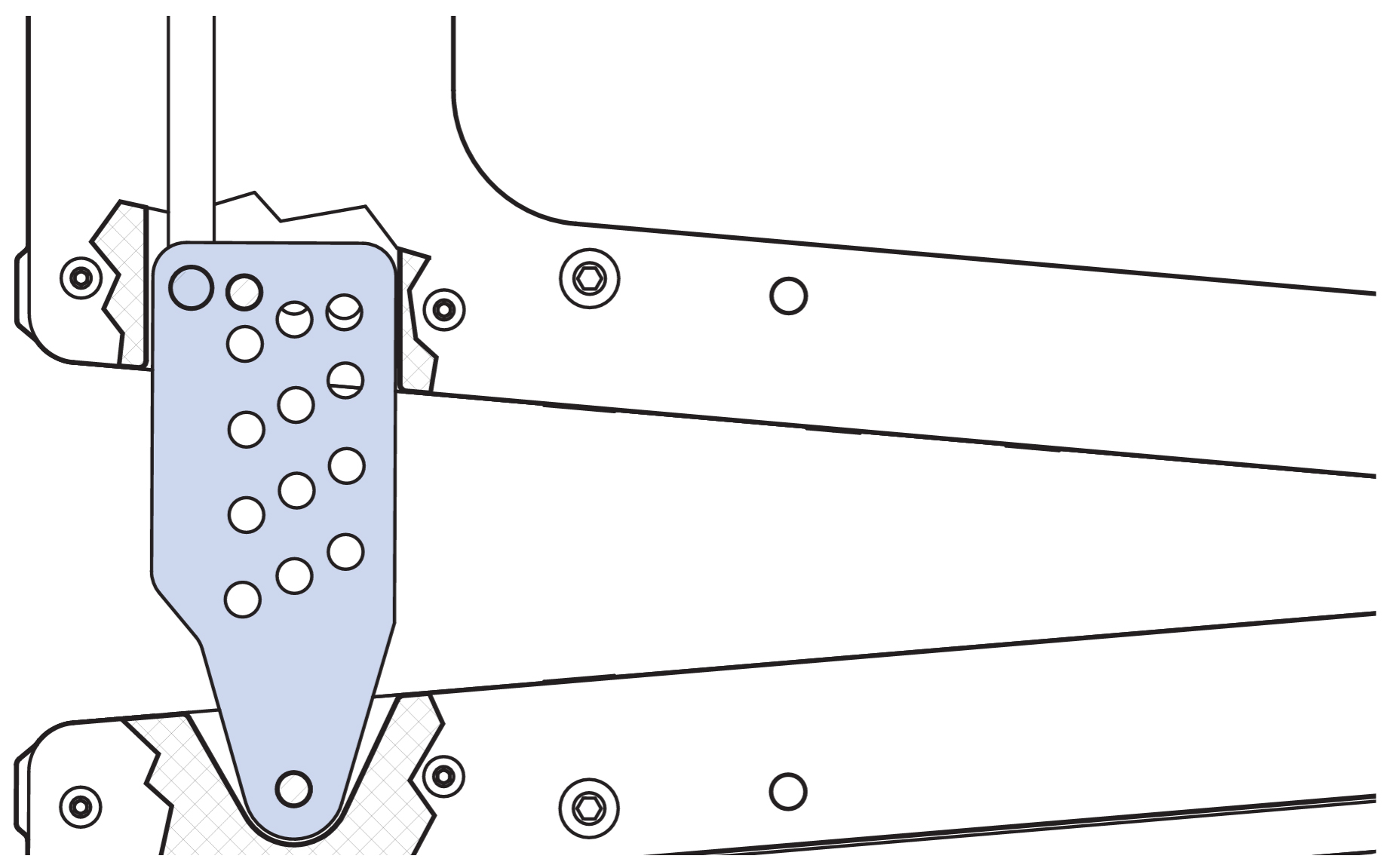
Rear GuideALinks
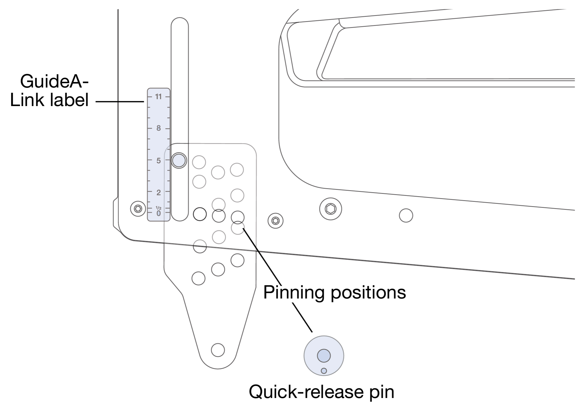
Rear GuideALink Label and Pinning Positions
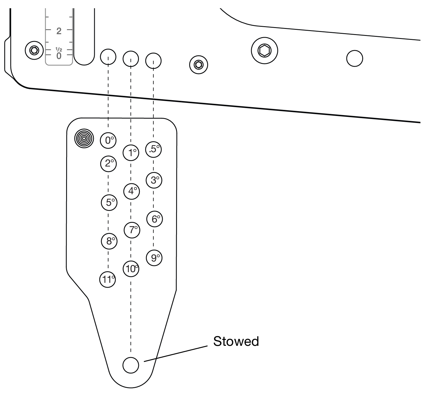
Rear GuideALink, Splay Angles for Linked LINAs
Note
The splay angles listed on the GuideALink label are for relative angles between the linked units. For example, setting the GuideALink to “5” yields a 5° downtilt of the lower unit relative to the upper unit. How the loudspeakers relate to the floor, stage, and seating angles in the venue depends on the orientation of the MG-MINA/LINA/750-LFC grid, the angles of the loudspeakers in the array above them, whether they are flown or ground-stacked, and other factors. Use MAPP system design software to determine the optimum splay angles for loudspeakers and coverage pattern of the array.
To achieve optimal acoustical performance for LINA arrays, use the appropriate number of units and splay angles to meet the coverage requirements of the venue. Utilize MAPP to verify designs and rigging configurations.
MG-MINA/LINA/750-LFC Grid
The MG-MINA/LINA/750-LFC grid, shown in the figure below, flies LINA arrays of up to 16 cabinets at a 5:1 safety ratio. The grid, which can also be used for groundstacking arrays, accommodates a variety of pickup configurations with four side pickup points and 11 center pickup points.
Note
Additional load ratings are possible. Use MAPP to verify load ratings.
For complete information about configuration and load ratings for the MG-MINA/LINA/750-LFC grid, as well as other LINA rigging accessories, refer to the MG-LINA/750-LFC Assembly Guide (PN 05.207.101.02) available at www.meyersound.com.
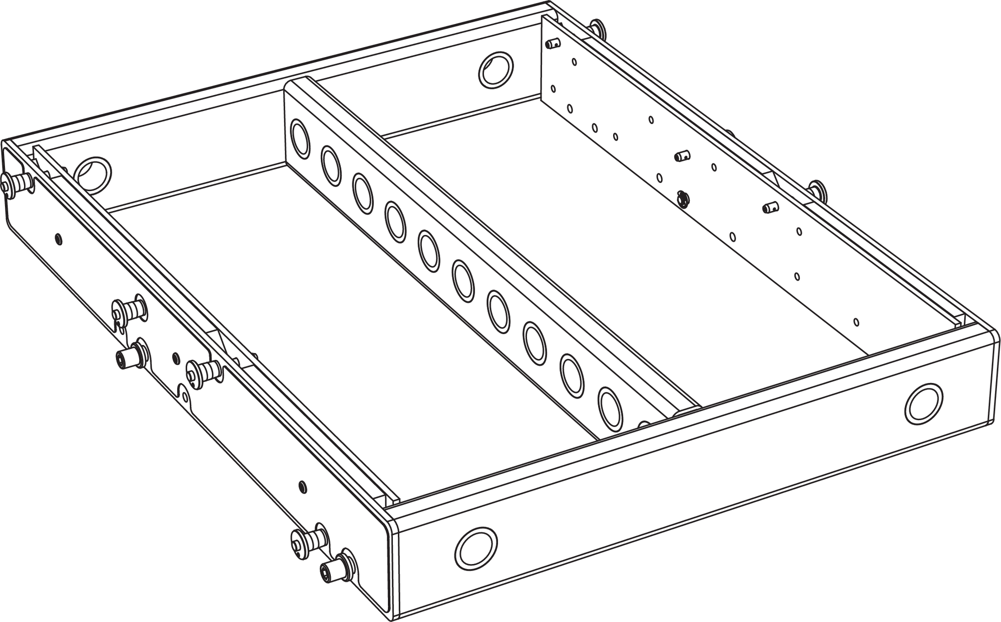
MG-MINA/LINA/750-LFC Grid
The MG-MINA/LINA/750-LFC grid has four captive links, two per side, that attach to the top LINA in flown arrays. The configuration of the links and orientation of the grid (for either maximum uptilt or maximum downtilt) determine the angle of the attached LINA. The grid links are easily stowed for transport and groundstacked configurations.
The MG-MINA/LINA/750-LFC grid includes eight (0.25 in x 0.90 in) quick-release pins: four for securing the four grid links, and four for securing LINA groundstacks to the top of the grid.
Caution
Always use the quick-release pins included with the MG-MINA/LINA/750-LFC grid to secure its links, as well as to secure groundstacked LINAs to the grid. Do not use the quick-release pins included with LINA in the grid as they are shorter and will not lock in place.
Tip
The MG-MINA/LINA/750-LFC grid can travel installed on top of LINA stacks.
MG-MINA/LINA/750-LFC Grid Orientations for Flown Configurations
The orientation of the MG-MINA/LINA/750-LFC grid determines the maximum downtilt and maximum uptilt for flown arrays.
MG-MINA/LINA/750 Oriented for Maximum Array Downtilt
When the MG-MINA/LINA/750-LFC grid is oriented with the links toward the front of the flown loudspeakers, the grid provides maximum downtilt for the flown array (when tilting the grid). The label on the MG-MINA/LINA/750-LFC shows this configuration as “Maximum Downtilt.”
With the maximum downtilt orientation, the LINA at the top of the array can be attached to the grid at 0° and –5° downtilt, as shown in the figure below.
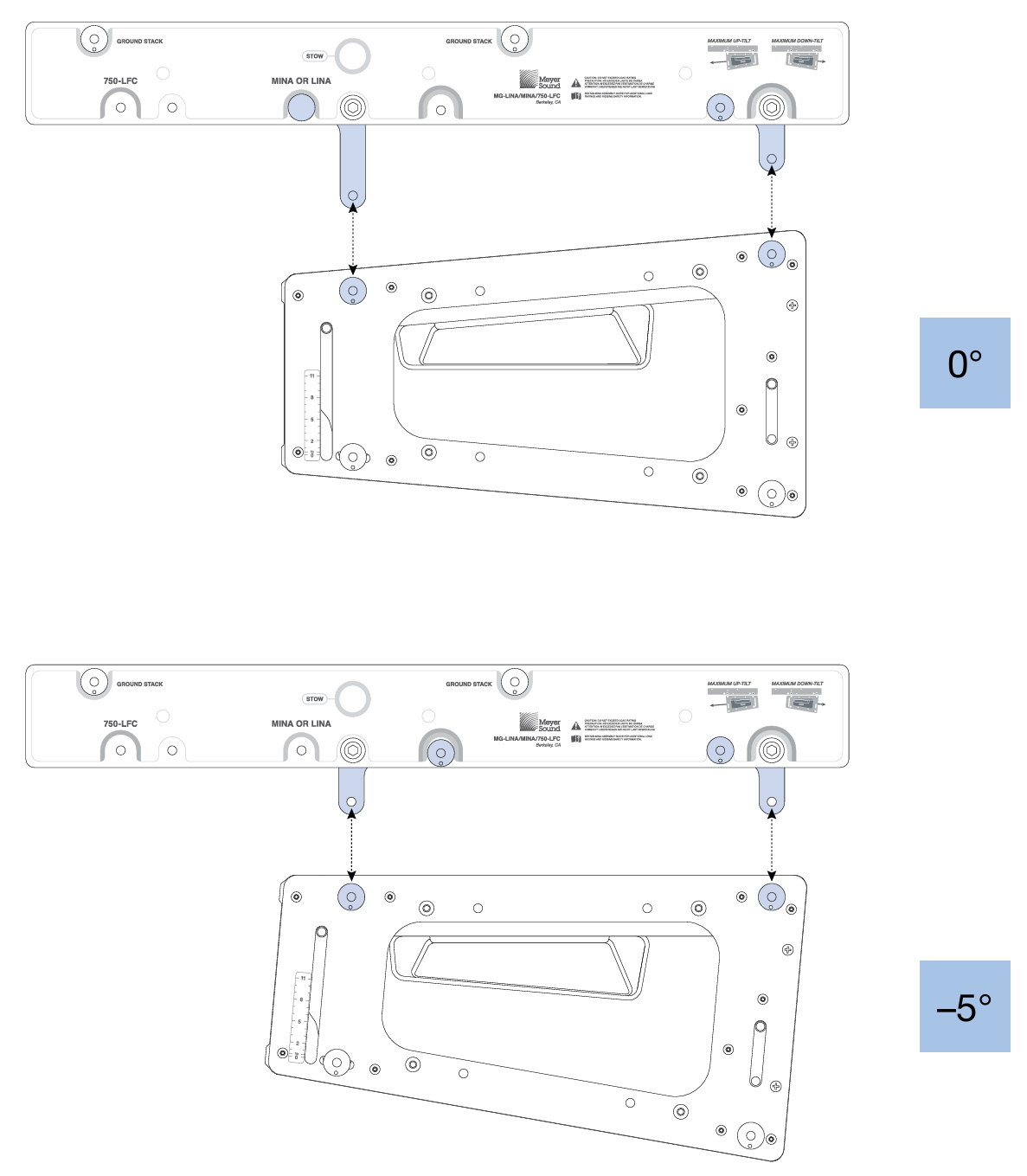 |
MG-MINA/LINA/750-LFC Grid, Maximum Downtilt Orientation, 0° and –5°
Tip
The tilt for the MG-MINA/LINA/750 and the array hung below it can be further tilted by using chain motors, or differing lengths of steel or SpanSets.
MG-MINA/LINA/750-LFC Oriented for Maximum Array Uptilt
When the MG-MINA/LINA/750-LFC grid is oriented with the links toward the rear of the flown loudspeakers, the grid provides maximum uptilt for the flown array (when tilting the grid). The label on the MG-MINA/LINA/750-LFC shows this configuration as “Maximum Uptilt.”
With the maximum uptilt orientation, the LINA at the top of the array can be attached to the grid at –5 and –10° downtilt, as shown in the figure below.
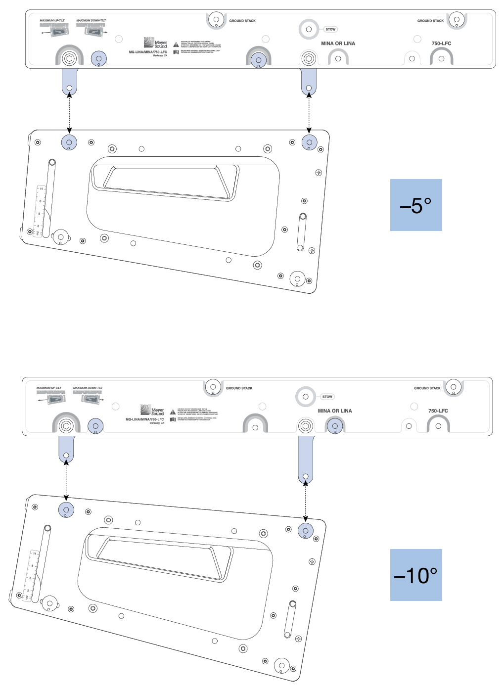
MG-MINA/LINA/750-LFC Grid, Maximum Uptilt Orientation, –5° and -10°
Tip
The tilt for the MG-MINA/LINA/750-LFC and the array hung below it can be further tilted by using chain motors, or differing lengths of steel or SpanSets.
:Use the MAPP System Design Tool’s prediction software to help determine the grid orientation that most appropriately balances the rigging load for a given application. It provides information such as the array COG (center of gravity) marker and front and rear rigging load weights.
MAPP System Design Tool Prediction Examples
Meyer Sound recommends using the MAPP System Design Tool to determine appropriate grid orientations. For example, the first figure below illustrates the MAPP software display when checking the COG (purple line extending upward) for maximum array uptilt, and the second figure below shows maximum downtilt.
The COG line is also useful when suspending the grid from a single center pickup point. Determine the appropriate point to use by observing which one of the 11 pickup points the COG line intersects.
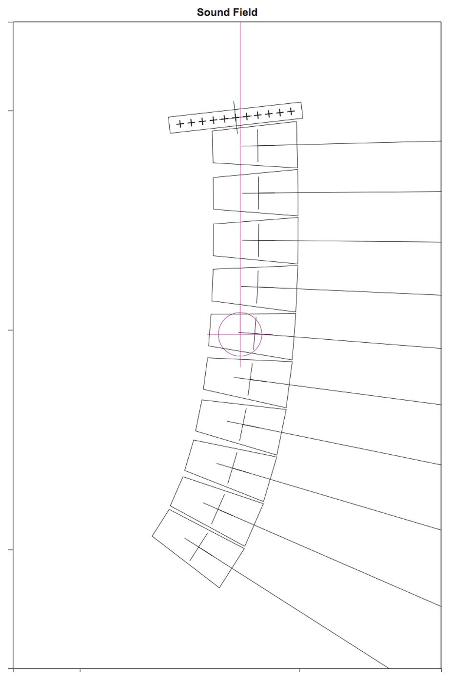
MAPP COG Maximum Downtilt
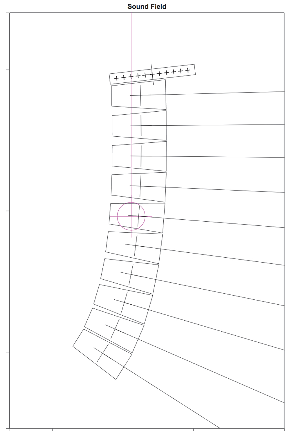
MAPP COG Maximum Downtilt
The MAPP software also provides weight distribution information. Use the grid orientation that has the least difference between the Front and Rear Rigging Loads calculated in the Flown Loudspeaker System Properties window, shown in the figure below.
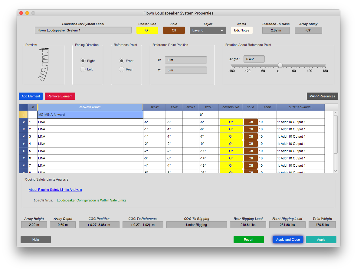
Balanced Rear and Front Rigging Loads.
Groundstacking LINAs with the MG-MINA/LINA/750-LFC
The MG-MINA/LINA/750-LFC grid can also be used for groundstacking up to six LINAs. When used for groundstacking, the grid should be oriented so the center of gravity for the stacked loudspeakers is near the center of the grid. The LINA at the bottom of the stack attaches directly to the grid with its GuideALinks and is secured with the quick-release pins included with the grid, as shown in the figure below. The configuration of the GuideALinks, shown in the second figure below, for the attached LINA determines its tilt, which can be from +6° (uptilt) to –5° (downtilt).
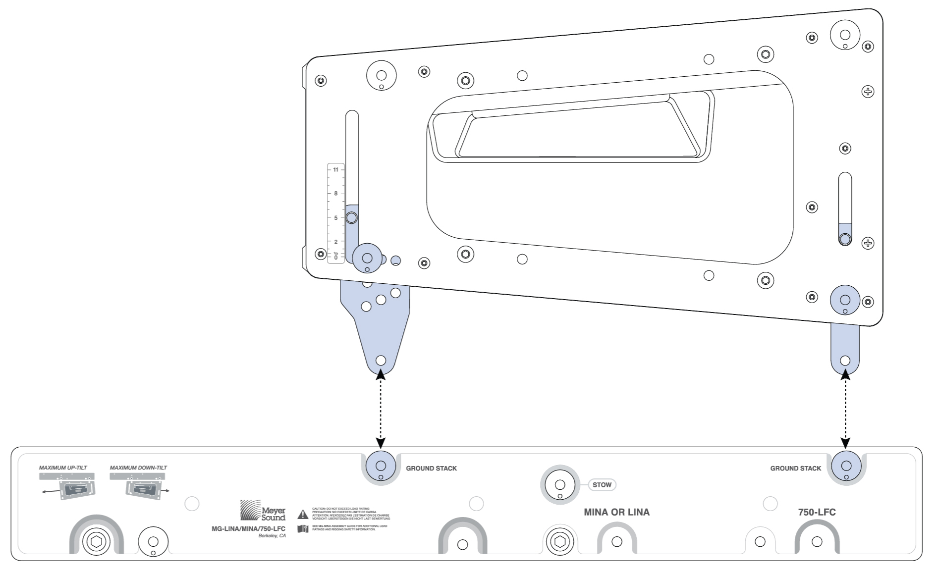
MG-MINA/LINA/750-LFC Grid with Groundstacked LINA
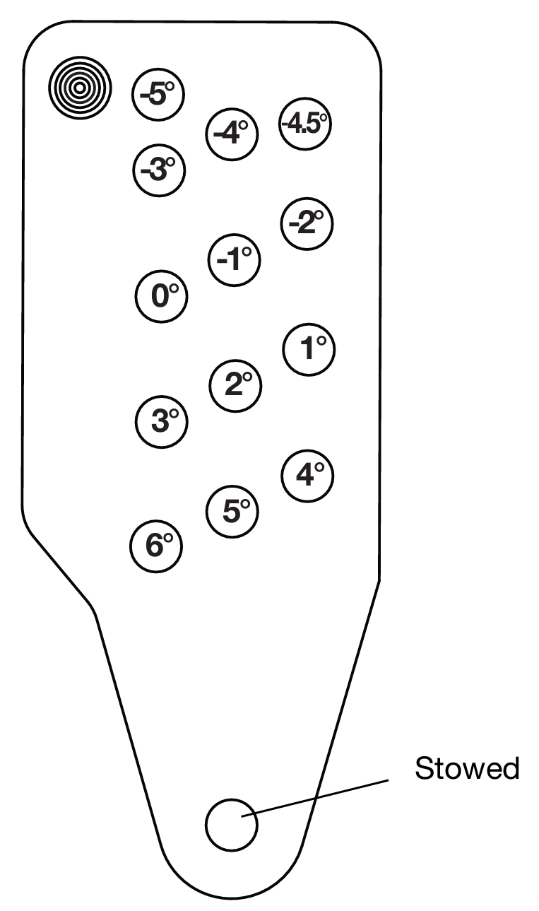
Rear GuideALink, Angles for Groundstacked Units
Caution
To secure groundstacked arrays, particularly in outdoor situations, use tie downs or weights with the grid and/or a safety system on the array.
MYA-MINA/LINA Mounting Yoke
The MYA-MINA/LINA mounting yoke flies up to three LINA loudspeakers from a single hanging point using a C-clamp or equivalent, as shown in the figure below, or pole-mounts up to two LINA loudspeakers with a third-party pole-mount adapter (see “Pole-Mounting LINAs with the MYA-MINA/LINA” on page 30). For flown applications, the yoke supports up to 30° of uptilt and severe downtilts of up to 90°. For flying larger arrays, the MG-MINA/LINA/750-LFC grid is recommended; for smaller profile applications, the MUB-MINA/LINA U-bracket is recommended.
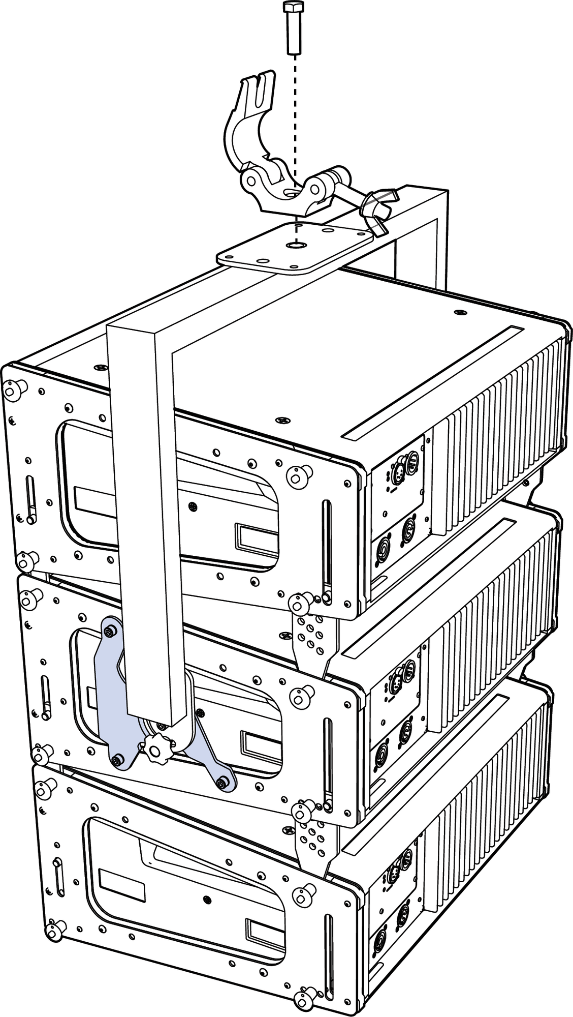
MYA-MINA/LINA with MPA-3 Adapter, Three LINAs, and third-party clamp
Caution
The MYA-MINA/LINA’s mounting bracket at the top of the yoke has one 1/2-inch center hole that is rated for flown applications. The smaller two center holes and four corner holes should only be used for attaching to pole-mount adapters
Note
For complete information about configuration and load ratings for the MYA- image6.pngMINA/LINA, as well as for other rigging accessories, refer to the MG-MINA/LINA/750-LFC Assembly Guide (PN 05.207.101.02).
MYA-MINA/LINA Bracket Options
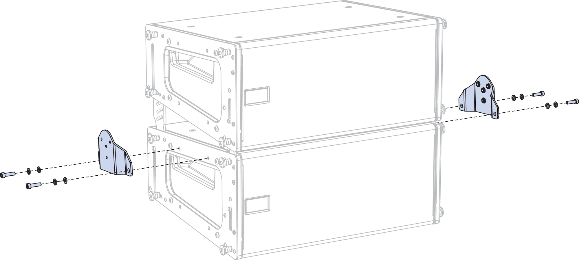
The yoke includes two bracketing options: the MPA-2 for attaching to two cabinets, and the MPA-3 for attaching to one or three cabinets. The bracket options allow the yoke to attach near the center of gravity for the loudspeakers. The brackets bolt directly to the LINA end frames with the M6 bolts and washers included with the yoke kit. For attaching to the yoke, the brackets include a center/pivot hole and three pinning holes to yield a wide range of uptilt and downtilt angles for the loudspeakers.
MPA-2 Bracket
When suspending two LINA cabinets with the MYA-MINA/LINA mounting yoke, use the MPA-2 bracket and attach it to the bottom cabinet, as shown in the figure below.
MPA-2 bracket
MPA-3 Bracket
When suspending one or three LINA cabinets with the MYA-MINA/LINA mounting yoke, use the MPA-3 bracket shown in the first figure below. When suspending three cabinets, attach the bracket to the center cabinet, as shown in the second figure below.

MPA-3 bracket
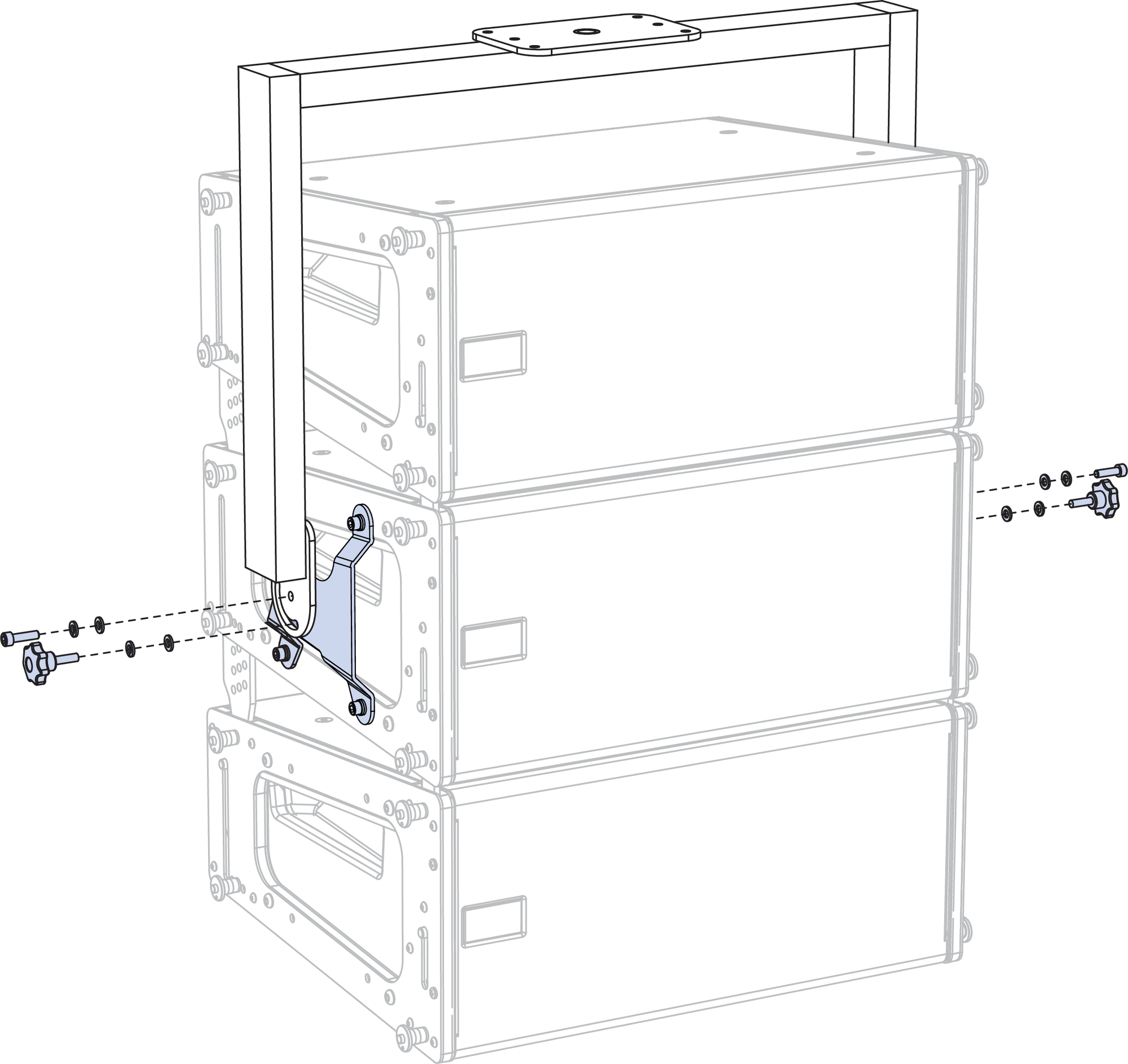 |
Flown MYA-MINA/LINA with MPA-3 bracket and Three LINAs
Pole-Mounting LINAs with the MYA-MINA/LINA
Up to two LINA loudspeakers can be pole-mounted with the MYA-MINA/LINA mounting yoke. For pole-mounting two LINA loudspeakers, use the MPA-2 bracket, shown in the figure below. For pole-mount applications, the yoke supports up to 30° of downtilt and severe uptilts of up to 90°. When pole-mounting LINAs with the yoke, the optional 35 mm pole stand adapter is required (PN 40.010.971.01).
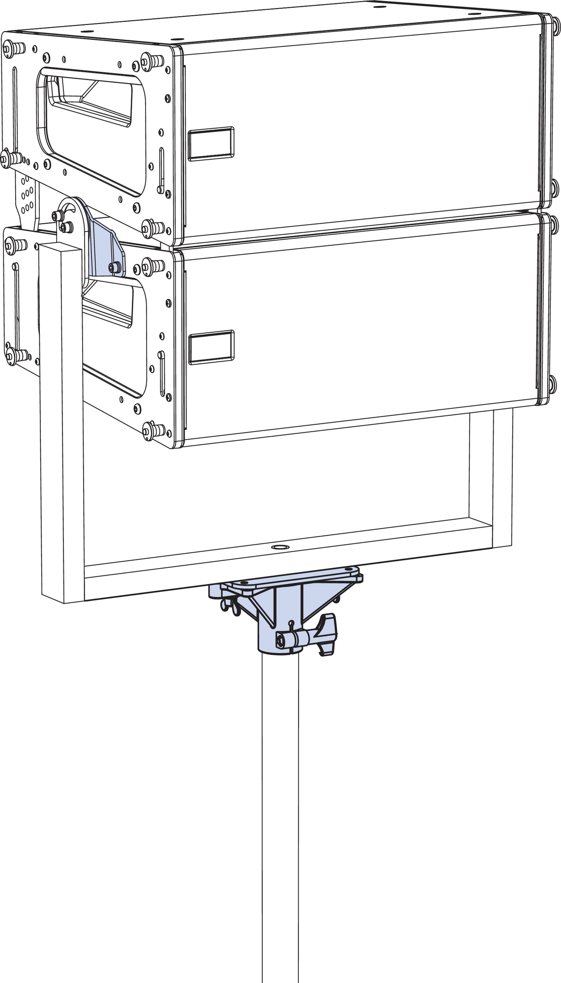 |
Pole-Mounted MYA-MINA/LINA with MPA-2 bracket and Two LINA loudspeakers with optional 35 mm pole stand adapter
Caution
When mounting the MYA-MINA/LINA on a pole, make sure the pole and pole-mount adapter have been rated to support the full weight of the yoke and loudspeakers. Observe all safety precautions specified by the pole and pole-mount adapter manufacturer.
MUB-MINA/LINA U-Bracket
The MUB-MINA/LINA U-bracket was primarily designed for aiming a single LINA loudspeaker in floor- and ceiling-mount configurations. However, the U-bracket is strong enough to fly arrays of up to five cabinets, or stack up to two cabinets in floor- and pole-mount configurations. With the U-bracket, up to two LINA loudspeakers can also be flown from trusses using C-clamps or the equivalent. For flying and groundstacking larger arrays, the MG-MINA/LINA/750-LFC grid is recommended; for applications requiring continuous adjustability or greater downtilt and uptilt angles, the MYA-MINA/LINA mounting yoke is recommended.
Note
For complete information about configuration and load ratings for the MUB-MINA/LINA, as well as for other rigging accessories, refer to the MG-MINA/LINA/750-LFC Assembly Guide (PN 05.207.101.02).
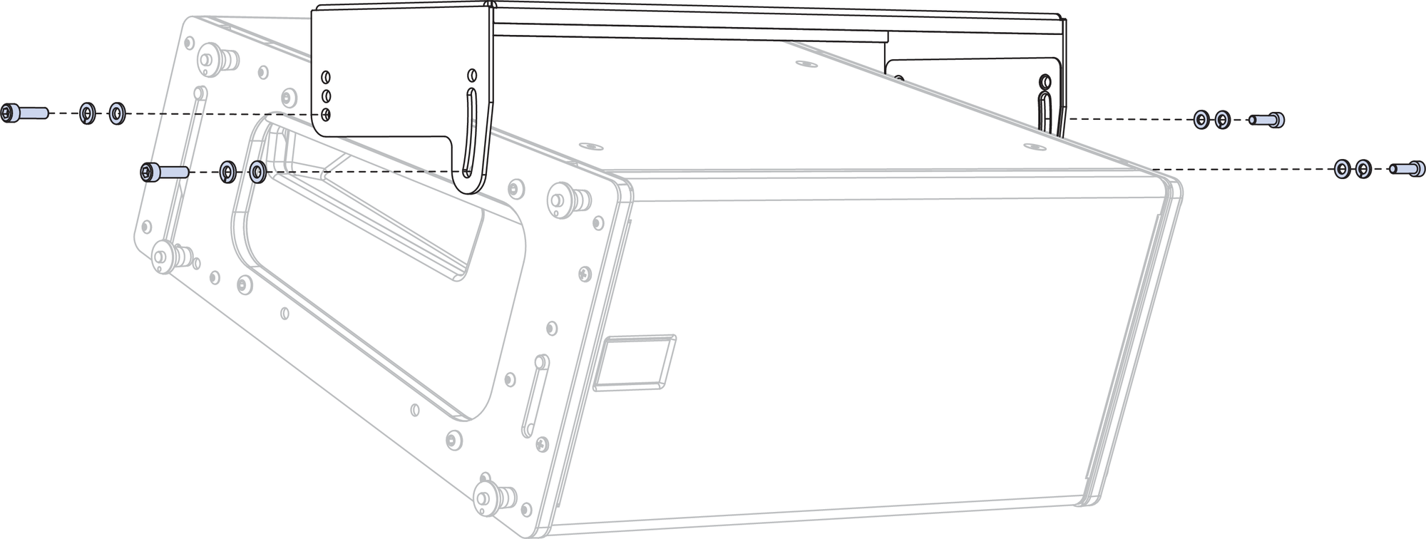
Ceiling-Mounted MUB-MINA/LINA with One LINA
The MUB-MINA/LINA U-bracket’s mounting holes and mounting slot provide maximum flexibility for the loudspeaker’s uptilt and downtilt. For flown applications, the MUB-MINA/LINA can be oriented for either maximum downtilt (with the slot near the front of the loudspeakers) or maximum uptilt (with the slot near the rear of the loudspeakers).
For a single flown cabinet, the MUB-MINA/LINA supports continuous angles of 0° to –20° in the maximum downtilt orientation, and angles of +10° to –10° in the maximum uptilt orientation.
For multiple flown cabinets, the MUB-MINA/LINA supports fixed angles of +10°, 0°, –5°, –10° and –20° (with either orientation).
Note
For multiple flown cabinets, the MUB-MINA/LINA slot is not recommended for variable adjustments, because the angle could change over time due to the weight of the cabinets.
For illustrations showing which MUB-MINA/LINA mounting holes and slot image6.pngconfigurations to use to achieve specific angles, refer to the MG-MINA/LINA/750-LFC Assembly Guide (PN 05.207.101.02).
Floor- and Pole-Mounting LINAs with the MUB-MINA/LINA
Up to two LINA loudspeakers can be floor or pole-mounted with the MUB-MINA/LINA U-bracket, shown in the figure below. When pole-mounting LINAs with the U-bracket, the optional 35 mm pole stand adapter is required (PN 40.010.971.01). For floor- and pole-mounted applications, the MUB-MINA/LINA can be oriented for either maximum downtilt (with the slot near the rear of the loudspeakers) or maximum uptilt (with the slot near the front of the loudspeakers).
For a single floor- or pole-mounted cabinet, the
MUB-MINA/LINA supports continuous angles from +10 to –10° in the maximum downtilt orientation, and angles of 0 to +20° in the maximum uptilt orientation.
For multiple floor- or pole-mounted cabinets, the
MUB-MINA/LINA supports fixed angles of 0, +5, and +10° (with either orientation).
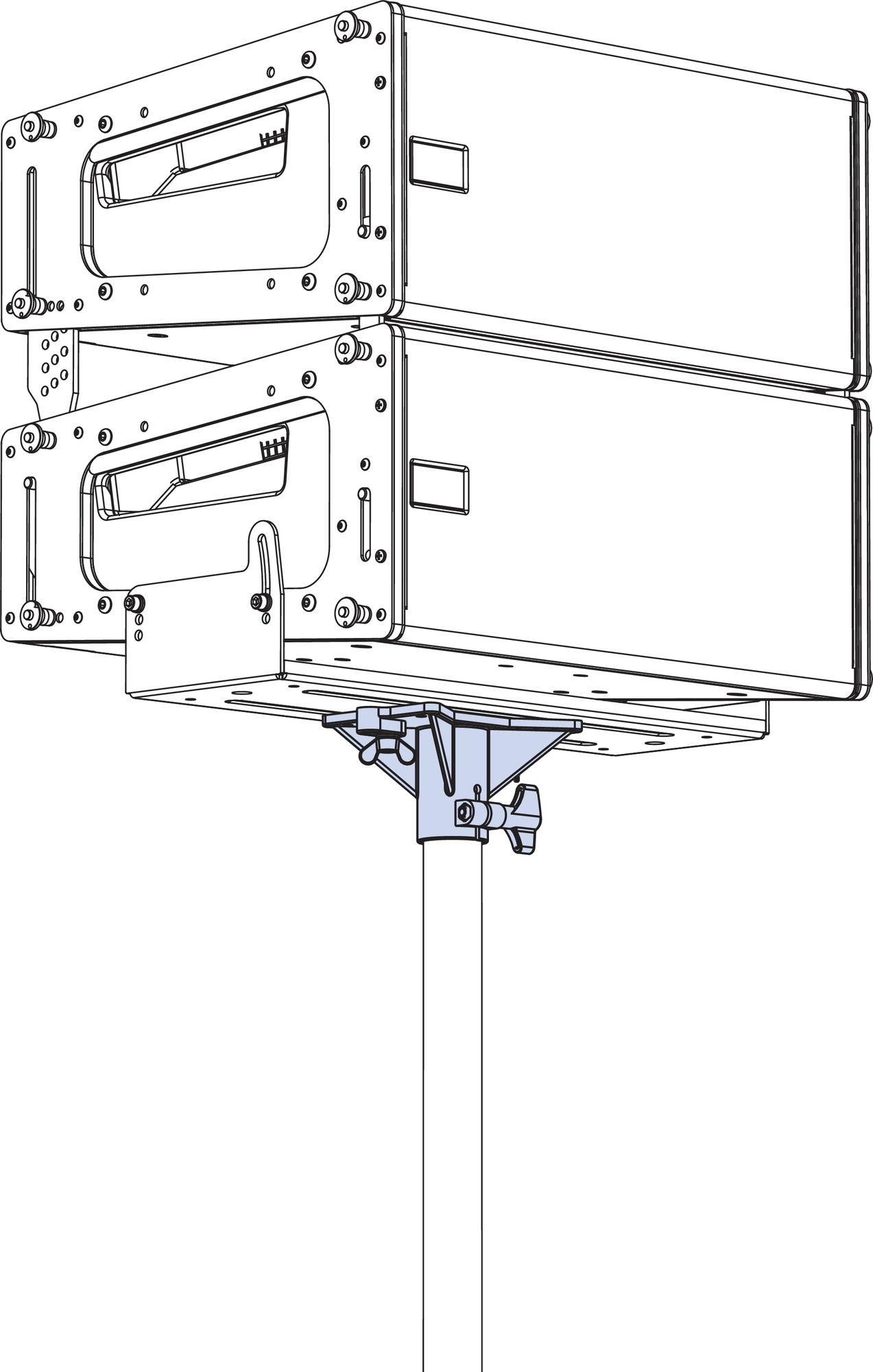
Pole-Mounted MUB-MINA/LINA/750 with Two LINA loudspeakers using the 35 mm pole stand adapter
Caution
When mounting the MUB-MINA/LINA on a pole, make sure the pole and pole stand adapter have been rated to support the full weight of the U-bracket and loudspeakers. Observe all safety precautions specified by the pole and pole-mount adapter manufacturer.
Note
For illustrations showing which MUB-MINA/LINA mounting holes and slot configurations to use to achieve specific angles, refer to the MG-MINA/LINA/750-LFC Assembly Guide (PN 05.207.101.02).
PBF-LINA Pullback Frame
For applications requiring extreme array downtilt that is not possible with adjustments to the motors attached to the grid, the optional PBF-LINA pull-back frame can be attached to the bottom cabinet in LINA arrays and pulled by a separate motor. The pull-back frame is secured to the bottom cabinet with the quick-release pins (0.25 in x 0.53 in, black button, PN 134.039) included with LINA. The PBF-LINA pull-back frame requires 1/2-inch shackles for its two pickup points.
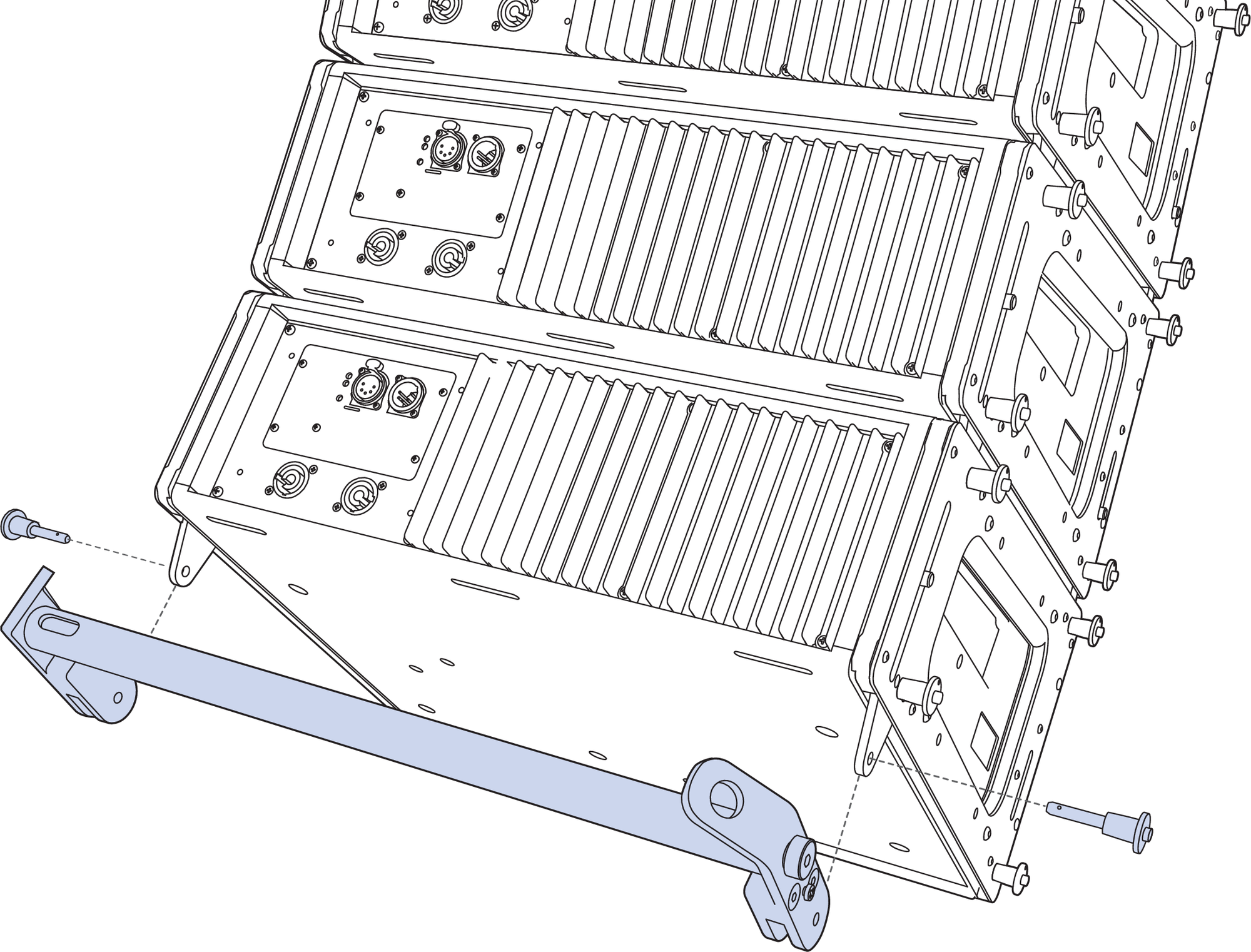
PBF-LINA Pull-Back Frame Attached to Bottom LINA, Exploded View
Note
For complete information about the PBF-LINA, as well as for other rigging accessories, refer to the MG-MINA/LINA/750-LFC Assembly Guide (PN 05.207.101.02).
MVP Motor Vee Plate
The optional MVP motor Vee plate fine-tunes the horizontal aim of LINA and 750-LFC arrays ±16 degrees. The bottom of the Vee plate attaches to the MG-MINA/LINA/750-LFC grid’s front-most or rear-most point on the center pickup bar, while the top corners of the Vee plate attach to two motors, which, when adjusted, affect the horizontal rotation of the grid. The Vee plate’s attachment points require 3/4- inch or 7/8-inch shackles. The Vee plate should always be placed on the grid side (front or rear) with the lower load value.
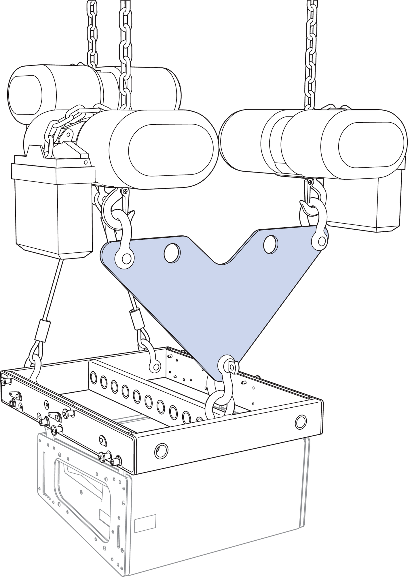
MVP Motor Vee Plate Attached to MG-MINA/LINA/750-LFC Grid
Caution
Always use properly rated rigging hardware. The MVP motor Vee plate requires 3/4-inch or 7/8-inch shackles for its attachment points.
Use MAPP to determine the weight distribution between the front and rear of the grid. Use the point(s) carrying the lesser weight to attach the MVP motor Vee plate.
Note
The MVP motor Vee plate is compatible with any Meyer Sound grid with front and rear center pickup points.
MCF-MINA/LINA Caster Frame
The MCF-MINA/LINA caster frame, shown in the first figure below, safely supports up to five LINAs, as shown in the second figure below, for transport and groundstacking, making it easy to assemble or disassemble arrays. The caster frame’s sturdy construction allows it be conveniently moved with forklifts.
Note
For complete information on the MCF-MINA/LINA, as well as for other rigging accessories, refer to the MG-MINA/LINA/750-LFC Assembly Guide (PN 05.207.101.02).
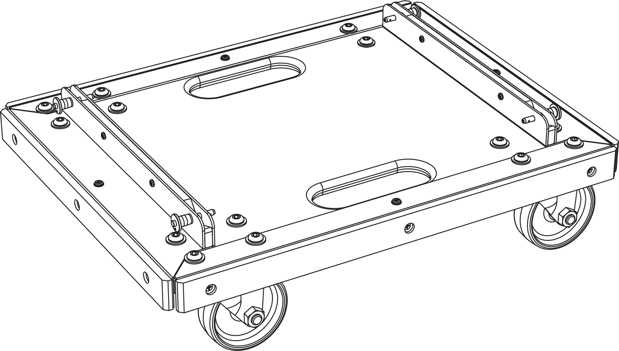
MCF-MINA/LINA Caster Frame
The LINA at the bottom of the stack attaches securely to the caster frame with its GuideALinks and is secured with the four (1/4 by 0.90-inch) quick-release pins included with the caster frame. The configuration of the GuideALinks for the attached LINA determines its tilt, which can be from +6° (uptilt) to –5° (downtilt).
Caution
Always use the quick-release pins included with the MCF-MINA/LINA caster frame to secure groundstacked LINAs to the grid. Do not use the quick-release pins included with LINA in the frame as they are shorter and will not lock in place.
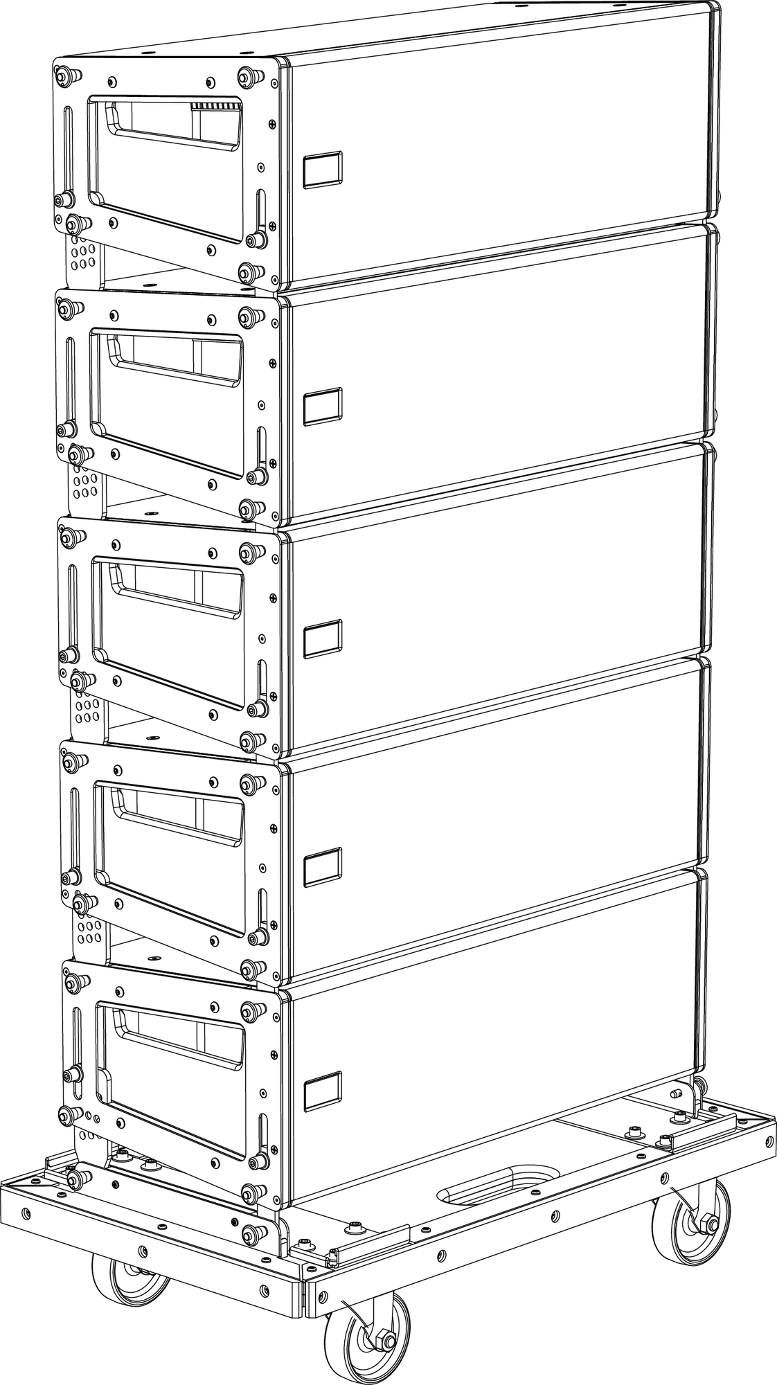
MCF-MINA/LINA Caster Frame with LINA Stack
Tip
The MG-MINA/LINA/750-LFC grid can travel installed on top of LINA stacks.
Durable nylon covers, sized for stacks of 3, 4, and 5 units, are available to ensure the LINA is completely road ready.
Safety Guidelines for the MCF-MINA/LINA Caster Frame
Do not stack more than five LINAs.
Avoid moving stacks in the front-to-back direction of the LINAs (the long side); always move stacks sideways to avoid tipping, as shown in the figure below.
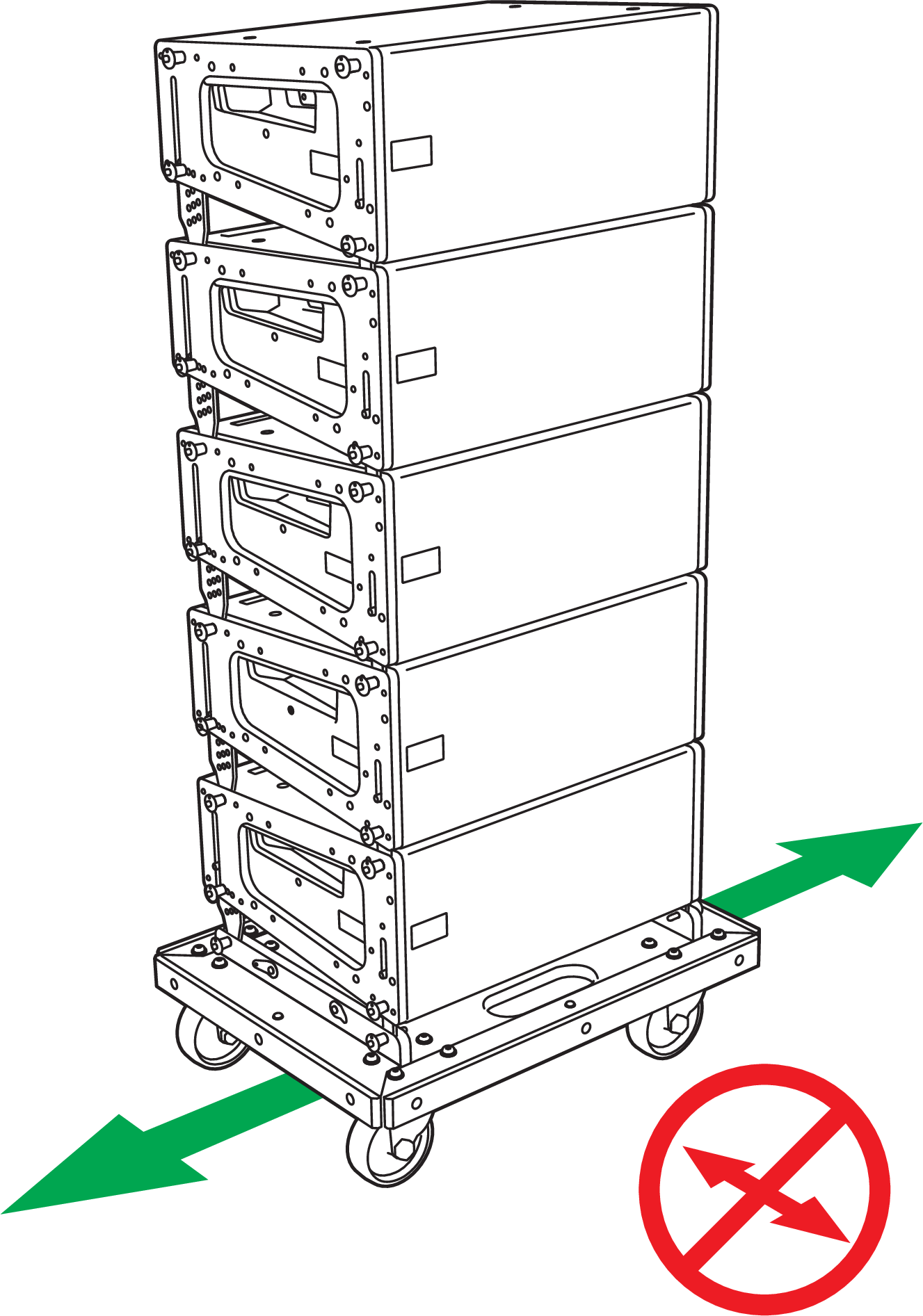
Avoid Moving Stacks in Front-to-Back Direction
When transporting a non-curved LINA stack with 0° splay angles, configure the rear GuideALinks for the bottom LINA so it is attached to the caster frame at 0° (using the 5° hole in the LINA GuideALinks).
When transporting a curved LINA stack with wide splay angles, configure the rear GuideALinks for the bottom LINA so it is attached to the caster frame at –5° (using the 0° hole in the LINA GuideALinks), to compensate for the stack’s center of gravity.
When groundstacking LINAs with the caster frame, make sure that all four caster wheels are blocked to prevent the stack from rolling away.
System Design and Integration Tools
MAPP System Design Tool
MAPP is a powerful, cross-platform application for accurately predicting the coverage pattern, frequency response, phase response, impulse response, and SPL capability of single or arrayed Meyer Sound loudspeakers.
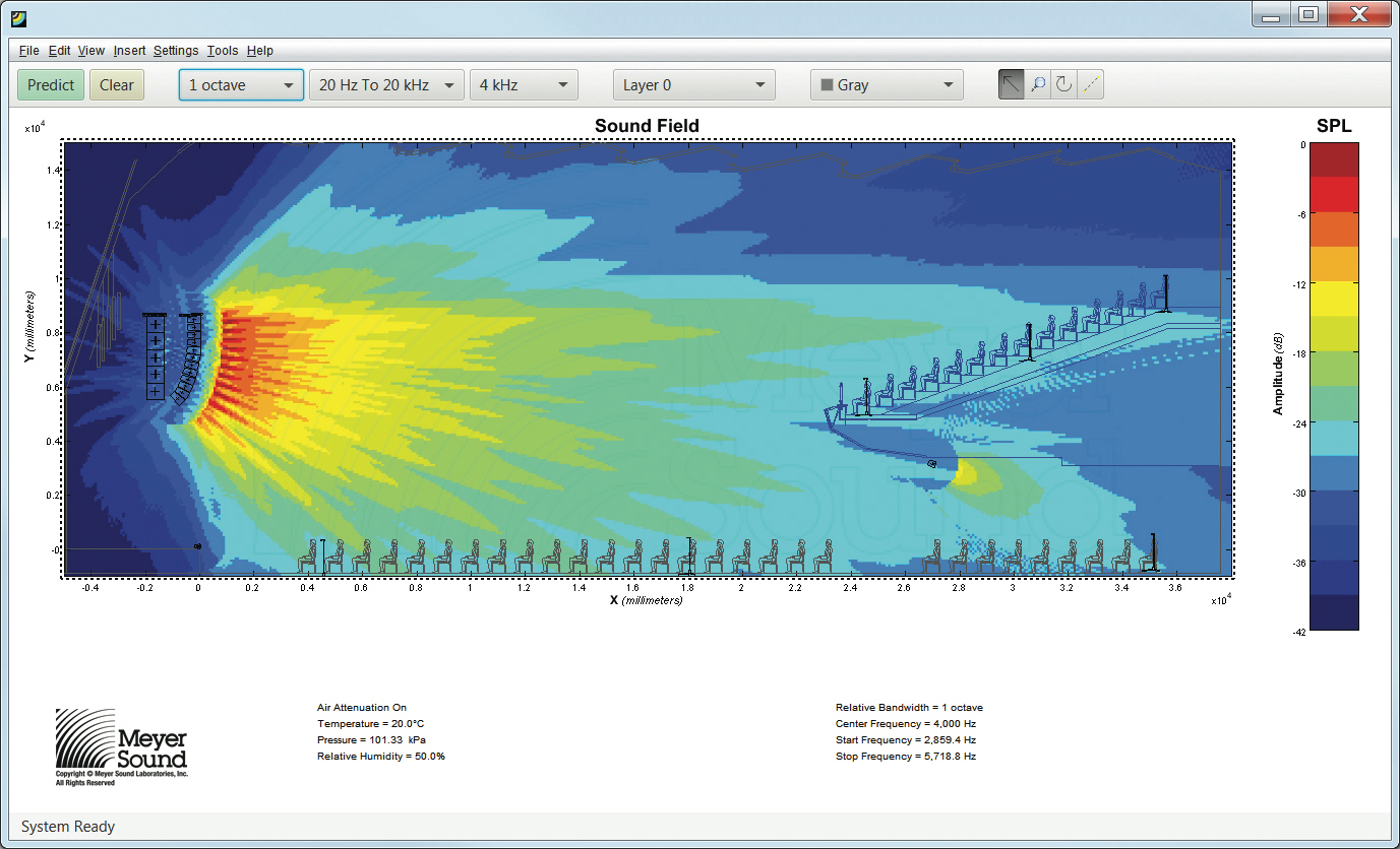
MAPP System Design Tool
Whether planning for fixed installations or for tours with multiple venues, you can use MAPP to accurately predict the appropriate loudspeaker deployment for each job, complete with coverage data, system delay and equalization settings, rigging information, and detailed design illustrations. MAPP’s accurate, high-resolution predictions ensure that systems will perform as expected, thereby eliminating unexpected coverage problems and minimizing onsite adjustments.
The key to the accuracy of MAPP’s predictions is Meyer Sound’s exhaustive database of loudspeaker measurements. Performance predictions for each loudspeaker are based on 720 1/48th-octave-band measurements taken with a SIM audio analyzer in the Meyer Sound anechoic chamber. The extraordinary consistency between Meyer Sound loudspeakers guarantees that predictions from MAPP will closely match their actual performance.
MAPP client software lets you configure Meyer Sound loudspeaker systems and define the environment in which they operate, including air temperature, pressure, humidity, and even the location and composition of surfaces. You can also import CAD (.DXF) files containing detailed venue information to act as a visual aid.
MAPP prediction requests are sent by the client software to Meyer Sound servers, where complex, high-resolution (magnitude and phase) polar data is processed with sophisticated acoustical prediction algorithms. The resulting predictions are then displayed in the MAPP client software.
With MAPP, you can:
Simulate different loudspeaker configurations to refine system design and determine the best coverage for intended audience areas
Monitor loudspeaker interactions to locate constructive and destructive interferences so that loudspeakers can be re-aimed and repositioned as necessary
Place microphones anywhere in the sound field and predict loudspeaker frequency response, phase response, and sound pressure levels as measured at each microphone position
Determine delay settings for fill loudspeakers using the Inverse Fast Fourier Transform feature
Preview the results of Galileo or Galileo Callisto processing to determine optimum settings for the best system response
Automatically calculate load information for arrays to determine rigging capacity, front-to-back weight distribution, and center of gravity location
Generate and export system images and full-system PDF reports for client presentations
MAPP Capabilities
With MAPP, you can:
Simulate different loudspeaker configurations to refine system designs and determine the best coverage for intended audience areas
Model loudspeaker interactions to locate constructive and destructive interferences so that loudspeakers can be re-aimed and repositioned as necessary
Place microphones anywhere in the Model View space and predict loudspeaker frequency response, phase response, and sound pressure levels at each microphone position
Determine delay settings for fill loudspeakers using the Inverse Fast Fourier Transform and phase response feature
Preview the results of signal processing to determine optimum settings for the best system response
Automatically calculate load information for arrays to determine necessary minimum rigging capacity, front-to-back weight distribution, and center of gravity location
Generate and export system images and system PDF reports for client presentations
Synchronize GALAXY processor output channel settings in real-time with virtual or real GALAXY units, allowing in-the-field changes to be predicted during system alignments
Sim Measurement System
The SIM audio analyzer is a high-resolution audio measurement system comprising software, hardware, microphones, and accessory cables. SIM presents measured audio frequencies at a resolution of 48 points per octave, where the 48 points per octave are arranged in even frequency increments in each octave group, equal to the total frequencies in that octave divided by 48. This resolution allows application of precise corrections to balance system response using frequency and phase domain information.
Source Independent Measurement Technique
The SIM 3 audio analyzer implements Meyer Sound's source independent measurement technique, a dual-channel method that accommodates statistically unpredictable excitation signals. Any excitation signal within a desired frequency range can be used to obtain highly accurate measurements for acoustical or electronic systems.
For example, during a performance, both the input signal and the measured output of the loudspeaker system can be captured and used as a SIM test signal, so you can:
View measurement data as amplitude versus time (impulse response) or amplitude and phase versus frequency (frequency response)
Utilize a single-channel spectrum mode
View frequency domain data with a logarithmic frequency axis
Determine and internally compensate for propagation delays using the SIM 3 Delay Finder
SIM Applications
SIM's main applications are testing and aligning loudspeaker systems, which entails:
Measuring propagation delays between subsystems to determine appropriate polarities and delay time
Verifying correct polarity
Measuring variations in frequency response caused by the acoustical environment and the placement and interaction of the loudspeakers to determine corrective equalization
Optimizing subwoofer integration
Optimizing loudspeaker arrays
The SIM audio analyzer can also be used in the following applications:
Microphone calibration and equalization
Transducer evaluation and correction
Echo detection and analysis
Vibration analysis
Architectural acoustics
Meyer Sound Weather Protection
The Weather Protection option from Meyer Sound is intended to increase the useful life of Meyer Sound loudspeakers when they are installed outdoors and exposed to different and often harsh weather conditions. Our Weather Protection includes a penetrating treatment to raw wood, use of special primers, and plating on all steel parts used (or alternatively, the use of stainless steel hardware). Weather Protection is designed to prevent malfunctions caused by harsh operating environments and slows the accelerated wear and tear that occurs in outdoor environments.
When Is Weather Protection Advisable?
Weather Protection is strongly recommended for all permanent outdoor installations where loudspeakers are directly exposed to the elements. This includes desert and semi-arid climates, where protection against dust and sand is important, and where infrequent rainstorms can contribute to deterioration of loudspeaker components.
Weather Protection is also recommended when the loudspeakers are sheltered from direct exposure to precipitation but are nevertheless exposed to prolonged high humidity, fog or mist. Examples would be installations on covered outdoor terraces or pavilions
Weather Protection is further advisable for portable or touring systems when any significant outdoor use is anticipated. Even though standard procedures may call for using external protective measures, these are often not implemented in time to prevent moisture intrusions that could lead to premature performance degradation of the loudspeaker.
Climate Variation and Owner Maintenance
The wear and tear on a loudspeaker will vary significantly with different climatic conditions. For example, a weather-protected loudspeaker installed in a sunlight-exposed location on an ocean pier will experience much harsher conditions than a loudspeaker in a similar installation that is shaded by trees and exposed only to rainfall. The constant exposure to direct UV radiation and salt air environment will cause a loudspeaker to wear more quickly than one with partial UV shielding and exposed only to freshwater moisture.
Wear can eventually affect the performance of the loudspeaker. It also affects aesthetics. For example, in salt air environments, the exterior grille can quickly show signs of oxidation, causing unsightly discoloration.
Apart from selecting suitable weather protection, the progress of wear and tear on the loudspeaker can be slowed by a regular schedule of inspection and cleaning. This maintenance is particularly necessary in harsh environments. Inspection and cleaning should include routine removal of any visible oxidation or environmental particulates, as these can accelerate metal corrosion or decay of the cabinet. If installed loudspeakers are not in use for an extended period, exterior protection or temporary removal and storage of the loudspeakers should be considered.
Benefits of Weather Protection
There are several benefits to selecting the Meyer Sound Weather Protection option:
Functionality - Weather Protection prolongs the service life of the loudspeaker by preventing premature degradation of internal components.
Safety - Weather Protection lessens the chance of electrical malfunctions or structural failures.
Warning
IT IS THE RESPONSIBILITY OF PURCHASERS/USERS/OPERATORS TO SELECT WEATHER PROTECTION WHEN APPROPRIATE FOR THEIR USE AND TO PERIODICALLY INSPECT THEIR LOUDSPEAKER INSTALLATIONS FOR ANY DETERIORATION THAT MAY LEAD TO SAFETY CONCERNS.
Aesthetics - Weather Protection slows wear and tear on the exterior of the loudspeaker in harsh conditions. Early signs of wear and tear on the exterior of the loudspeaker indicate over-exposure to the elements.
Standards Compliance - Weather Protection helps in meeting IP ratings for loudspeakers. IP ratings are an internationally recognized standard often used in installations involving our products. A further explanation of IP ratings is given in the IP Ratings.
Weather Protection Components
Standard Weather Protection
Meyer Sound designs toward an IP rating of IPX4 (see IP Ratings) for Standard Weather Protection, which includes the following components:
Wood treatment — Prior to cabinet manufacturing, the raw wood receives a special treatment that penetrates and stabilizes the wood fibers to withstand a wide range of temperatures and exposure to extreme humidity.
Cabinet finishing — The assembled cabinets receive a highly impervious finish that includes a sealing primer and a finishing topcoat. The coatings are applied on both surfaces, with one coat on the interior and two on the exterior. The final step is a two-part modified acrylic urethane similar to that used in military applications.
Driver treatment — All cone drivers are coated with a water-resistant sealant.
Exterior protection — Grille frames are coated to resist corrosion, and all components that mount to the cabinet use custom gaskets and stainless steel fasteners.
Removable rain hood — The rain hood is designed to shield connectors even in wind-driven rain.
Installation Practices
Meyer Sound assumes normal and accepted installation practices are used when installing Meyer Sound Loudspeakers outdoors. Deviation from such practices may cause weather protection to be ineffective and void the warranty for the loudspeaker.
Examples of unacceptable and acceptable installation practices include:
Loudspeakers installed outdoors should not face upward.
Loudspeakers with a rain hood should be installed in such a way that the rain hood opening is not facing any direction but down.
Meyer Sound-supplied rigging components should not be modified (for example, by drilling additional holes in a MUB for mounting to a wall). When an installer/integrator modifies a Meyer Sound supplied rigging component to support their installation method, it is considered compromised and out of warranty.
All loudspeaker cabling must be installed with a "drip-loop" or equivalent method to ensure that rain/ water is NOT wicked toward the loudspeaker.
If in doubt about an installation method, contact Meyer Sound Technical Support for assistance.
Always discuss the environmental conditions of your Meyer Sound installation with your Sales Manager, and verify the availability of Weather Protection for your selected loudspeaker models. The Sales Manager, together with Technical Support, will verify the appropriate level of weather protection for the loudspeakers and related rigging hardware.
IP Ratings
IP stands for "Ingress Protection." The current format for expressing an IP rating is a 2-digit code. The first digit of an IP rating represents protection from solid objects. The second digit of an IP rating represents protection from water or moisture. The table below provides a chart of IP ratings and the corresponding definitions of the rating.
Note
IP ratings only apply to the "ENCLOSURE." A loudspeaker is considered an enclosure and as such we can apply an IP rating to it. Rigging hardware is not an enclosure and therefore IP ratings do not apply. Also, cable and cable-mount connectors used to connect to the loudspeaker are NOT part of the enclosure and therefore not part of the IP rating. Only the chassis-mounted part of the connector is considered part of the enclosure.
First Digit (Protection against solid objects) | Definition | Second Digit (Protection against liquids) | Definition |
|---|---|---|---|
X | Characteristic numeral is not required to be specified. | X | Characteristic numeral is not required to be specified. |
0 | No protection | 0 | No protection |
1 | Protected against solid objects over 50mm. | 1 | Protected against vertically falling drops of water. |
2 | Protected against solid objects over 12 mm. | 2 | Protected against direct sprays up to 15° from the vertical. |
3 | Protected against solid objects over 2.5mm. | 3 | Protected against direct sprays up to 60° from the vertical |
4 | Protected against solid objects over 1 mm. | 4 | Protected against direct sprays from all directions. Limited ingress permitted |
5 | Protected against dust. Limited ingress permitted. | 5 | Protected against low-pressure jets of water from all directions. Limited ingress permitted. |
6 | Totally protected against dust. | 6 | Protected against strong jets of water from all directions. Limited ingress permitted. |
7 | Protected against the effect of temporary immersion between 15cm and 1m. | ||
8 | Protected against the effect of long-term submersion of 1m or more. |
Rain Hoods
Weather-protected LINAs include a rain hood for indoor/outdoor touring and sheltered outdoor installations. Meyer Sound offers three rain hood models: A fixed rigid rain hood for permanent installations, a collapsible hood for portable applications, and an Ultra Weather Protection rain hood that has improved corrosion resistance (see Appendix C, “ULTRA Weather Protection Version” and Appendix D, “LINA UW Rain Hood and Shield Attachment”). Please specify the desired rain hood when ordering.
Rigid Rain Hood
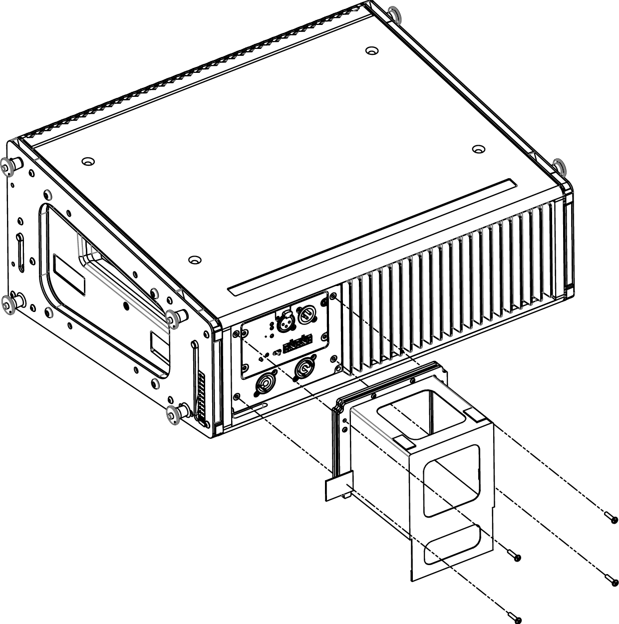
The LINA rigid removable rain hood is easily attached and removed with the included four screws, as shown in the figure below.
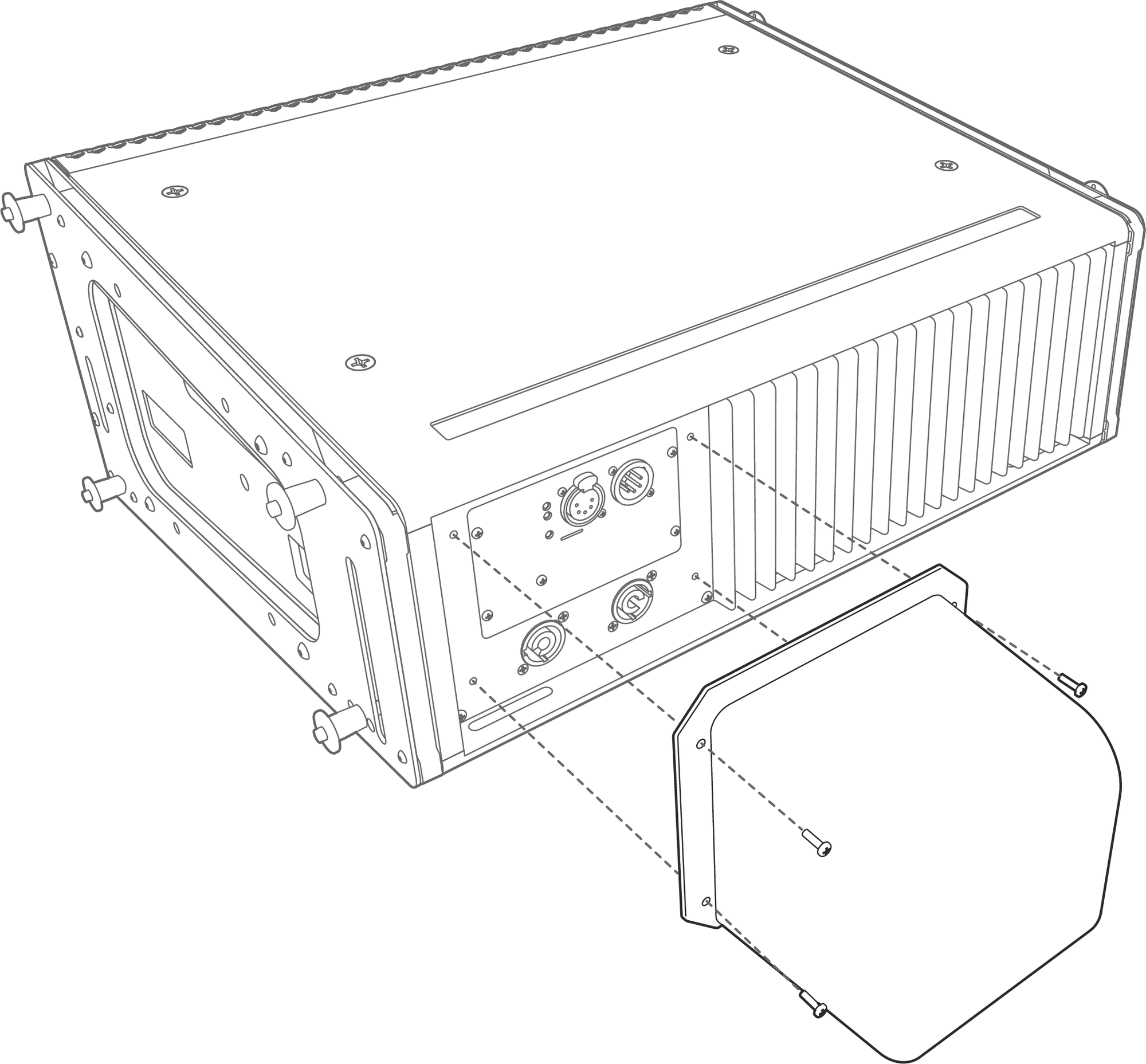
LINA with rigid rain hood
Attach any required cables to the LINA loudspeaker.
Attach the rain hood to the user panel, and secure it to the center of the panel with its four 6-32 screws.
Make sure to tighten the screws to create a good seal against the user panel. The recommended torque value for rainhood screws is 10–12 in-lbs (1.1-1.4 N·m).
Caution
There is only one proper loudspeaker orientation once the rainhood is installed, as shown in the figure above.
The weather-protected LINA must be mounted with a 0° tilt, or preferably with a slight down-tilt. This angle shields the driver from the elements and does not allow water to accumulate. Do not tilt the cabinet up, as the drivers and cabinet will accumulate water.
Note
Weather-protected units using the rigid rainhood are rated IPX4 for water intrusion.
Collapsible Rain Hood
The LINA collapsible rain hood is installed on the unit when shipped. Four screws secure its frame permanently, as shown in the figure below.
LINA with collapsible rain hood
Detach the Velcro straps and extend the rain hood.
Extend the lower flap for splash protection.
Attach any required cables to the LINA.
The clear windows let you easily locate the connectors on the user panel.
To stow the rain hood, reverse the steps.
Caution
There is only one proper loudspeaker orientation once the rainhood is installed, as shown in the figure above.
The weather-protected LINA must be mounted with a 0° tilt, or preferably with a slight down-tilt. This angle shields the driver from the elements and does not allow water to accumulate. Do not tilt the cabinet up, as the drivers and cabinet will accumulate water.
Parts List
The Ultra Weather Protection LINA Rain Hood includes the following parts:
LINA Rain Hood with attached gasket (PN 45.268.035.03)
LINA UW Rain Hood Shield (PN 64.268.129.01)
4 pan head Phillips 6-32 x 0.5-inch stainless-steel screws (PN 101.031)
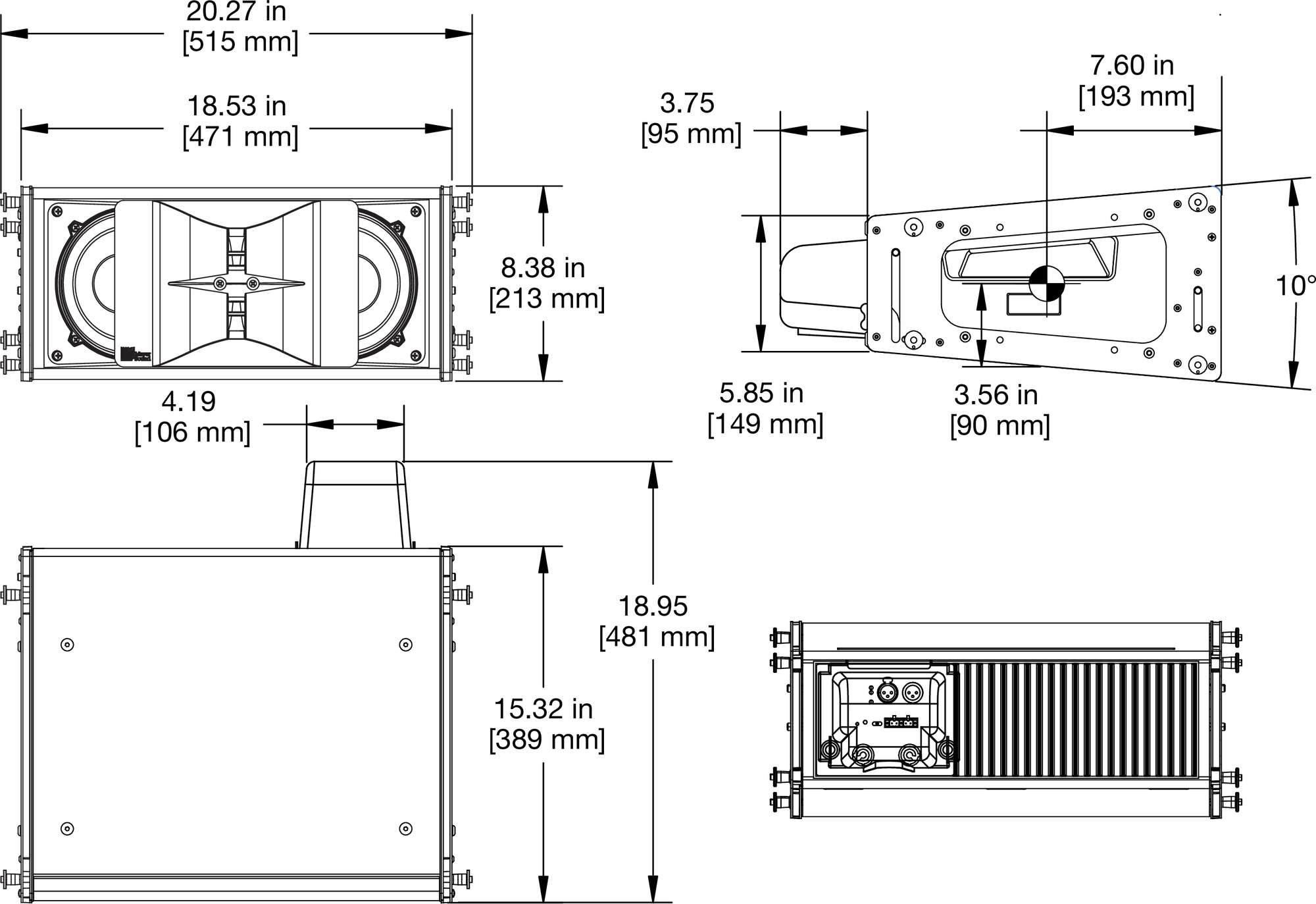
LINA Dimensions
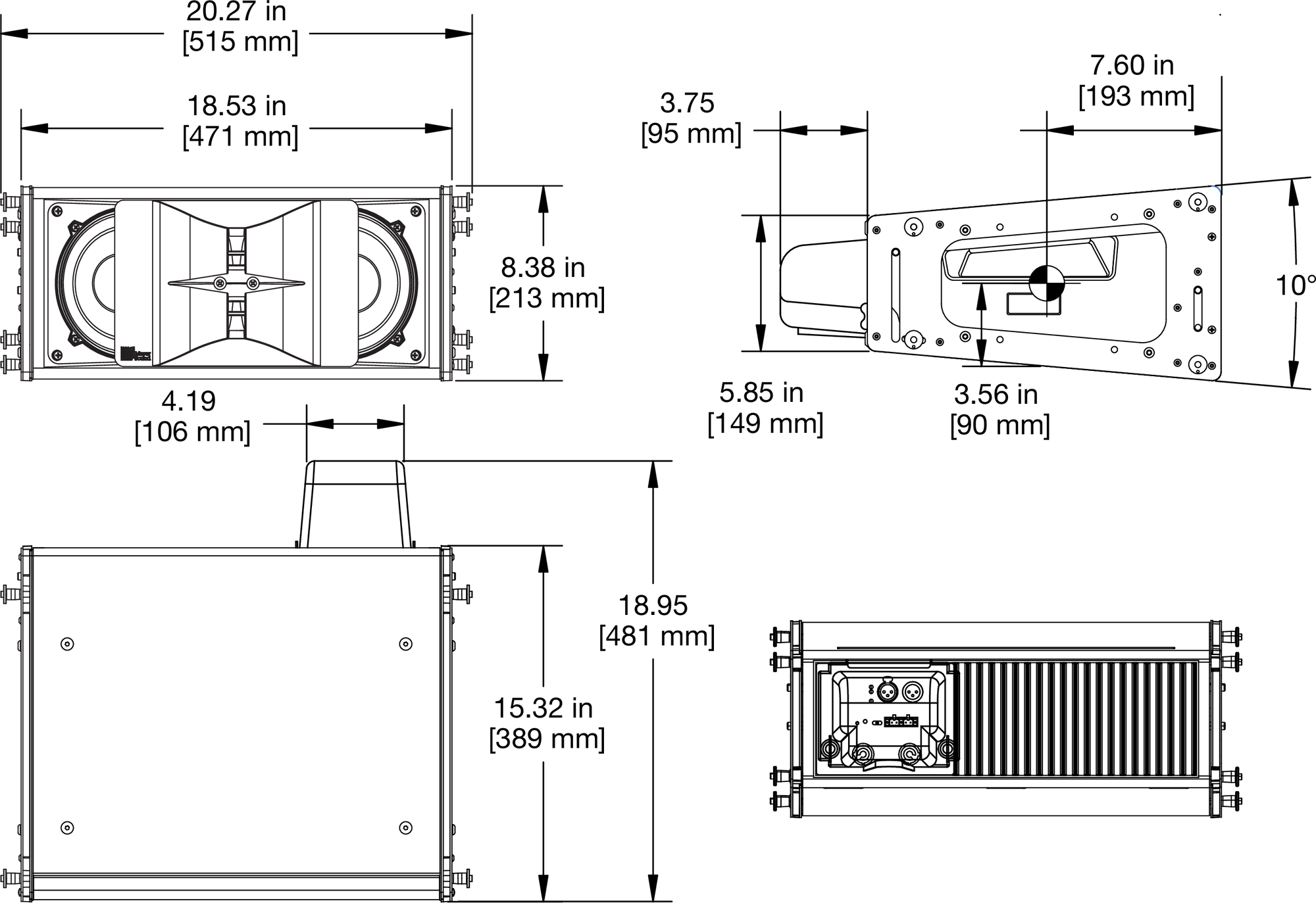
LINA Dimensions with Rain Hood
