Operating Instructions — HMS
Cinema Surround


The HMS cinema surround loudspeaker is optimized for use in cinemas, high-end private theaters, screening rooms, and other surround applications. Designed to complement Meyer Sound’s Acheron™ screen channel loudspeakers, the self-powered HMS maintains a wide dynamic range, exceptional fidelity, and precise clarity during the most demanding of digital soundtracks. Boasting a wide frequency range and a generous linear peak SPL with very low distortion, the HMS delivers the full intensity and nuance of cinema surround channels to every listener without compromise.
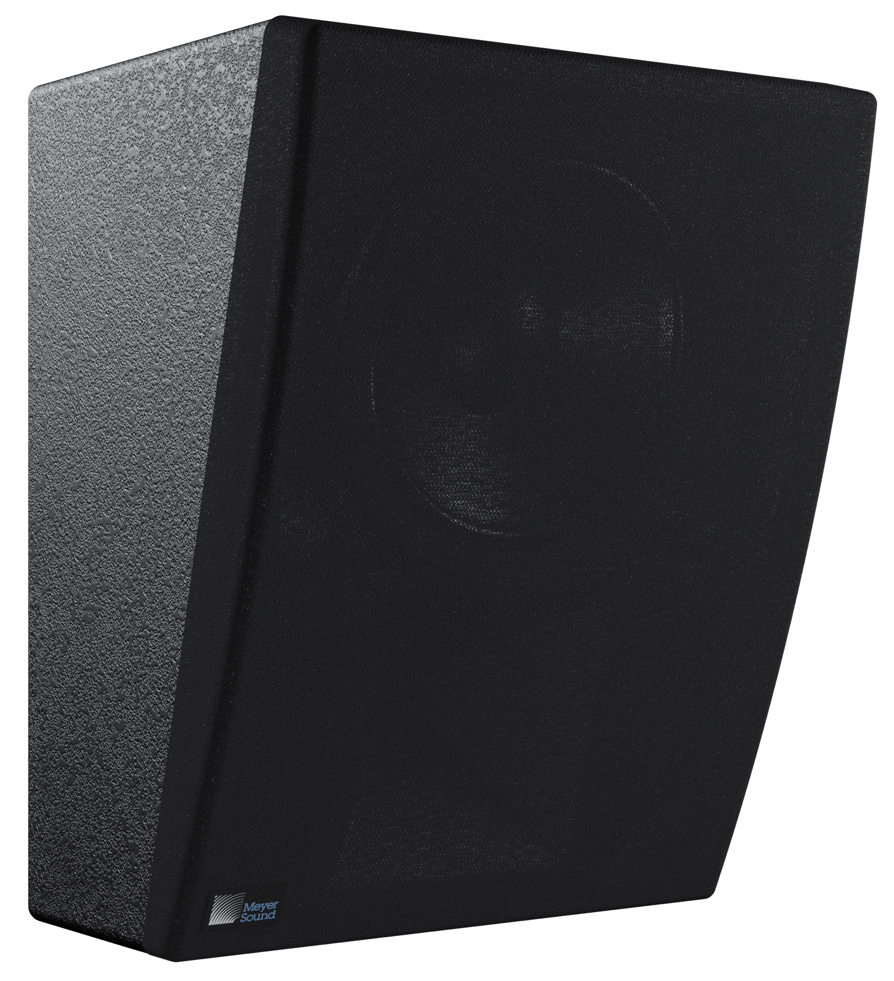
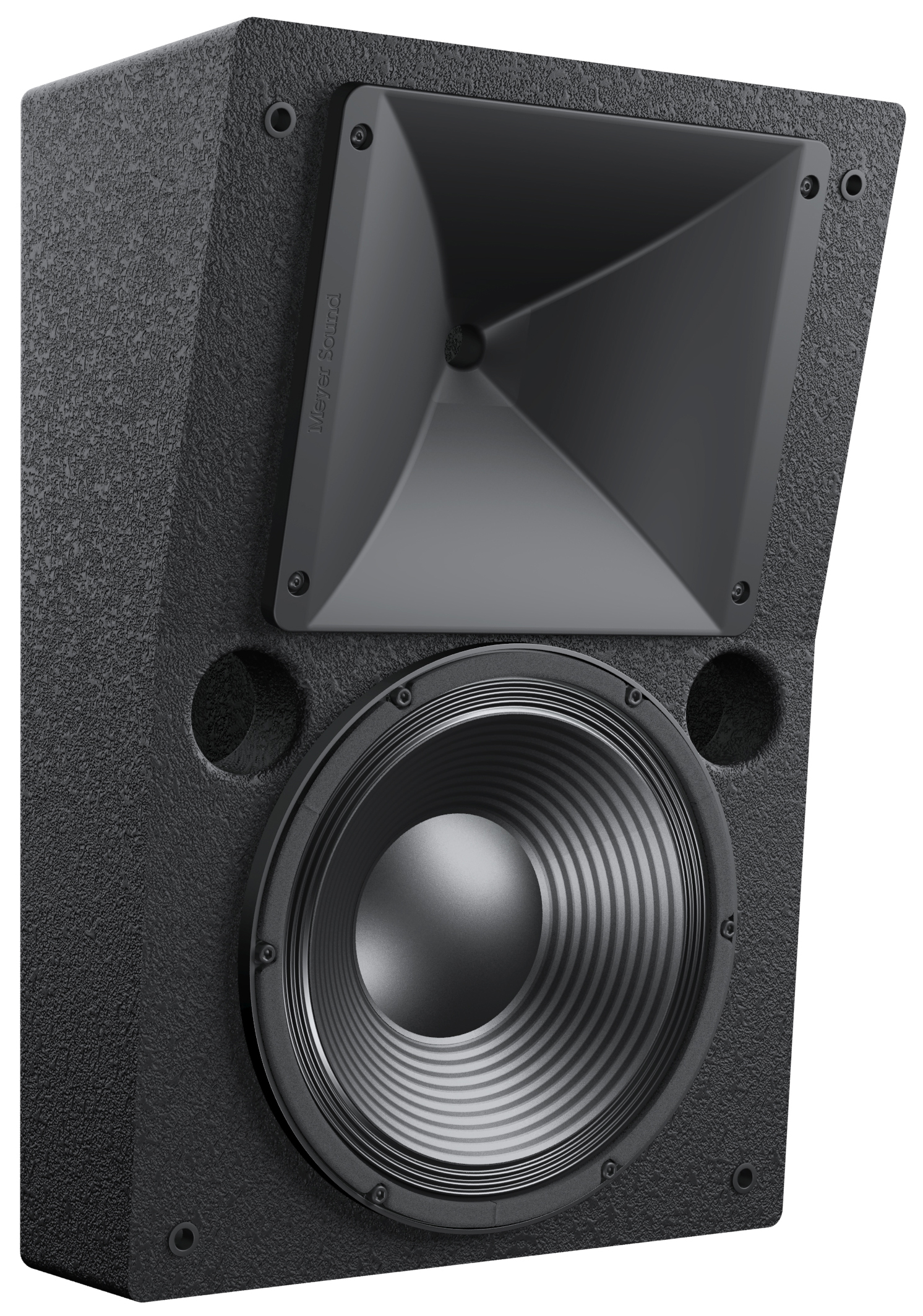
HMS-10 Cinema Surround Loudspeaker (With Grille)
The HMS cinema surround loudspeaker is available in five models: HMS-5, HMS-10, HMS-12, HMS-15, and HMS-15AC, ranging in size, weight, driver size, and power to accommodate a wide range of venues and applications. The proprietary long-excursion cone drivers and diaphragm compression drivers are driven by an onboard amplifier that includes an active crossover, driver protection circuitry, and correction filters for flat phase and frequency response. A constant-directivity horn provides uniform, full-range, consistent coverage.
The HMS-5, HMS-10, HMS-12, and HMS-15 are equipped with IntelligentDC technology and receive DC power and balanced audio from composite Phoenix™ 5-pin connectors. Powering the loudspeakers from an external DC source eliminates the need for AC conduits while preserving the advantages of self-powered systems. IntelligentDC loudspeakers require an MPS-488HP external power supply. The single-space 19-inch rack unit distributes DC power and balanced audio to up to eight HMS-5, HMS-10, or HMS-12 loudspeakers, or up to four HMS-15 loudspeakers. Composite multiconductor cables, such as Belden® 1502 or equivalent, can deliver both DC power and balanced audio to loudspeakers at cable lengths up to 150feet with just 1dB of loss in peak SPL using 18AWG wire. Longer cable runs are possible with heavier gauge wire. The MPS-488HP is optionally available with an RMS™ remote monitoring system module for monitoring voltage and current draw for its attached loudspeakers from a Mac® or Windows®-based computer.
The HMS-15AC is an AC-powered version of the HMS-15. Its IntelligentAC™ power supply provides automatic voltage selection, EMI filtering, soft current turn-on, and surge suppression. The HMS-15AC is optionally available with its own onboard RMS remote monitoring system module for comprehensive monitoring of loudspeaker parameters from a Mac or Windows-based computer.
The versatile HMS can be suspended or mounted on walls or ceilings at fixed or adjustable angles with optional halfyoke, U-bracket, or wall-mount brackets, allowing it to be deployed per the requirements of any surround application or immersive cinema format.
Meyer Sound’s industry-leading self-powered technology not only delivers unparalleled and consistent audio fidelity but also simplifies installation, whether designing new rooms from scratch or adding surround channels to existing installations. The HMS cabinet features a black textured finish and an acoustically transparent, detachable, black cloth grille that blend smartly with any theatre decor.
These operating instructions document the following HMS loudspeakers:
HMS-5 compact cinema surround loudspeaker
HMS-10 cinema surround loudspeaker
HMS-12 high-power cinema loudspeaker
HMS-15 high-power cinema loudspeaker
Note
For the sake of brevity, when referring to these loudspeakers collectively, this document will refer to them as HMS loudspeakers.
The AC-powered HMS-15AC is not documented in these operating instructions. For information about it, refer to the HMS-15AC Operating Instructions (PN05.242.005.01).
HMS-5 Compact Cinema Surround Loudspeaker
Cinema Surround
The HMS-5 compact cinema loudspeaker includes two
5-inch low-frequency, long-excursion cone drivers, and one 2-inch diaphragm high-frequency compression driver on a symmetrical, constant-directivity 80-degree horn. The loudspeaker is powered by a 3-channel amplifier with an active crossover. The cabinet is constructed of multi-ply hardwood and includes 3.94 inches x 3.94 inches (100 mm x 100 mm) rear attachment points for optional mounting hardware.
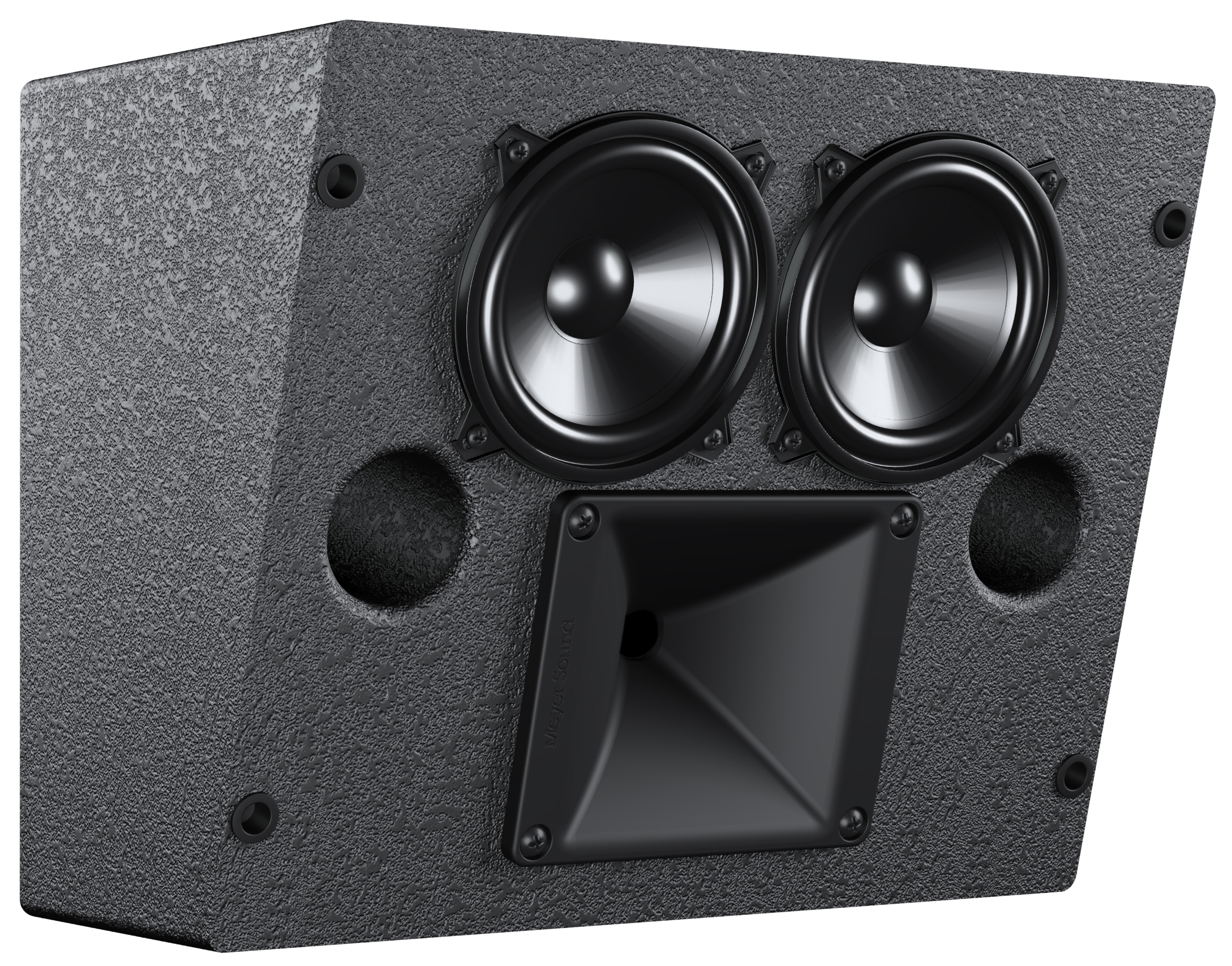
HMS-5 Compact Cinema Surround Loudspeaker (Without Grille)
HMS-10 Cinema Surround Loudspeaker
Cinema Surround
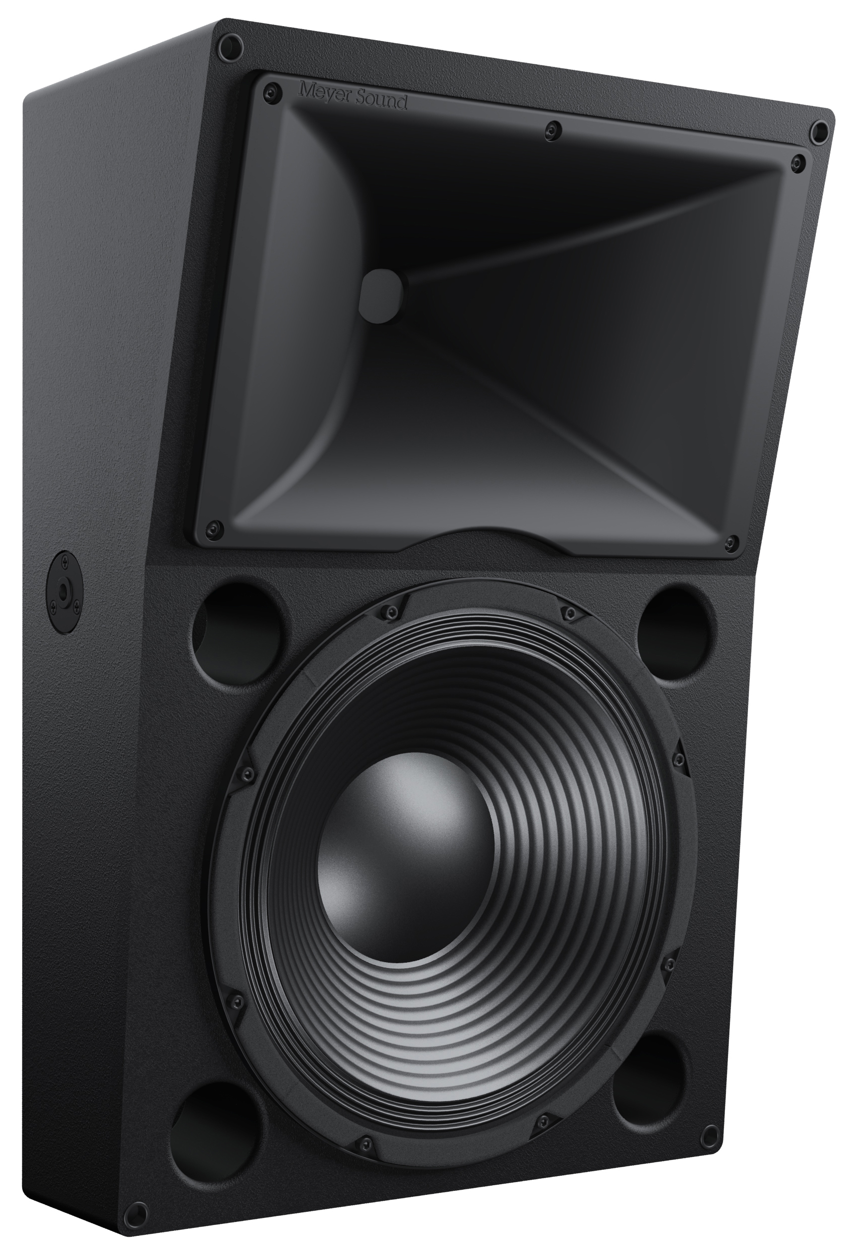
The HMS-10 cinema loudspeaker includes one 10-inch low-frequency, long-excursion cone driver, and one 2-inch diaphragm high-frequency compression driver on a symmetrical, constant-directivity 80-degree horn. The loudspeaker is powered by a 2-channel amplifier with an active crossover. The cabinet is constructed of multi-ply hardwood and includes 3.94 inches x 3.94 inches (100 mm x 100 mm) rear attachment points for optional mounting hardware.
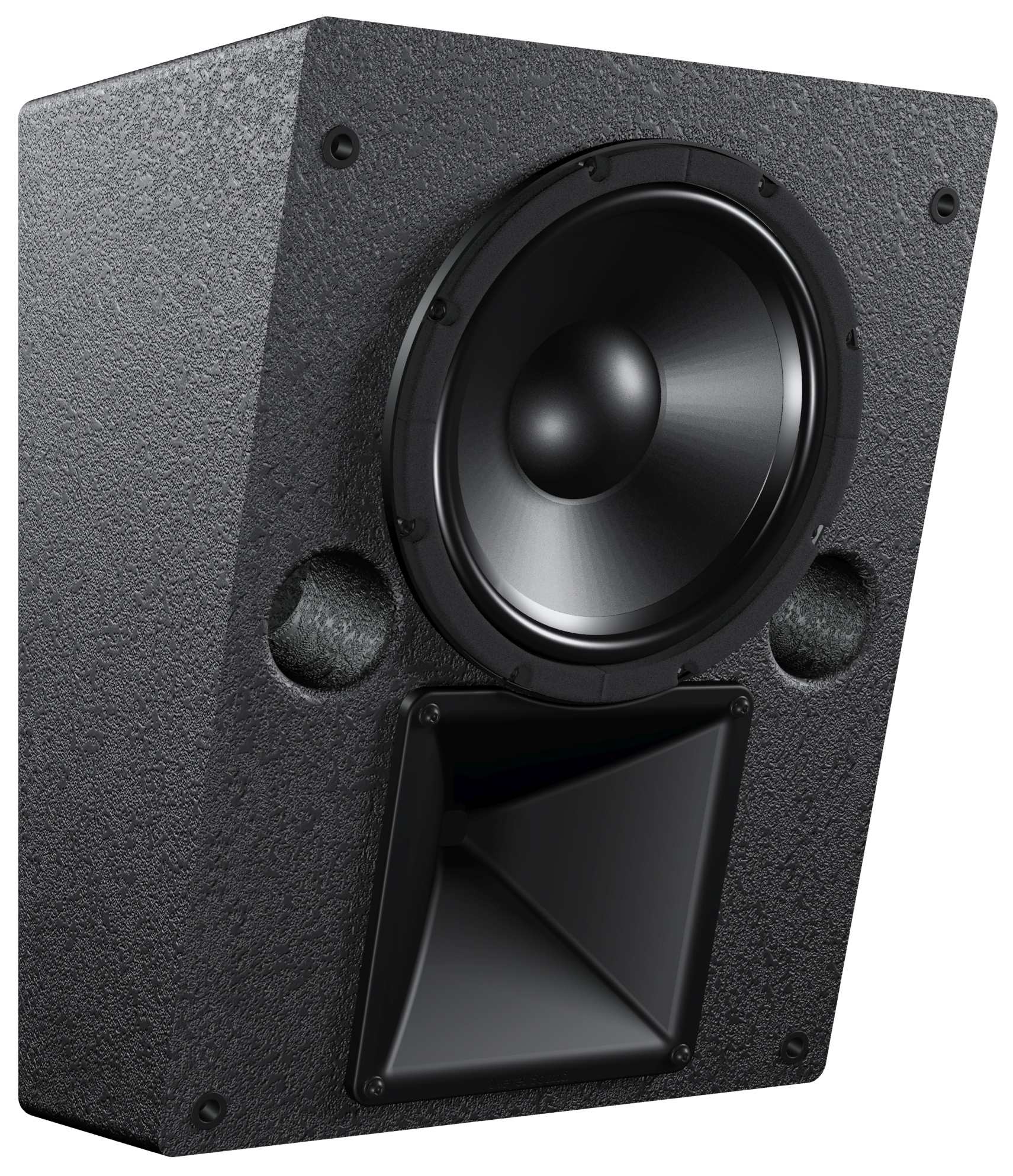
HMS-10 Cinema Surround Loudspeaker (Without Grille)
HMS-12 High-Power Cinema Surround Loudspeaker
Cinema Surround
The HMS-12 high-power cinema loudspeaker includes one 12-inch low-frequency, long-excursion cone driver, and one 3-inch diaphragm high-frequency compression driver on a symmetrical, constant-directivity 100-degree horn. The loudspeaker is powered by a 2-channel amplifier with an active crossover. The cabinet is constructed of multi-ply hardwood and includes 3.94 inches x 3.94 inches (100 mm x 100 mm) rear attachment points for optional mounting hardware.
HMS-12 High-Power Cinema Surround Loudspeaker (Without Grille)
HMS-15 High-Power Cinema Surround Loudspeaker
Cinema Surround
The HMS-15 high-power cinema loudspeaker includes one 15-inch low-frequency, long-excursion cone driver, and one 3-inch diaphragm high-frequency compression driver on a symmetrical, constant-directivity 80-degree horizontal by 50-degree vertical horn. The loudspeaker is powered by a 2-channel amplifier with an active crossover. The cabinet is constructed of multi-ply hardwood and includes 5.00 inches x 2.75 inches (127 mm x 70 mm) rear attachment points and side attachment points with 3/8”-16 threads for optional mounting hardware.
HMS-15 High-Power Cinema Surround Loudspeaker (Without Grille)
HMS Loudspeakers
Single Channel Input Connectors (HMS-5, HMS-10, and HMS-12)
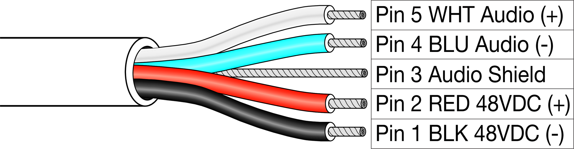
The HMS-5, HMS-10, and HMS-12 loudspeakers receive DC power and balanced audio from a single Phoenix 5-pin male Input connector. The connector includes two pins for DC power (positive and negative) and three pins for balanced audio (positive, negative, and shield). The pins are clearly labeled on the HMS user panel. To function properly, the HMS-5, HMS-10, and HMS-12 require an MPS-488HP IntelligentDC power supply (one channel output per loudspeaker). The MPS-488HP can power up to eight single-channel HMS loudspeakers.
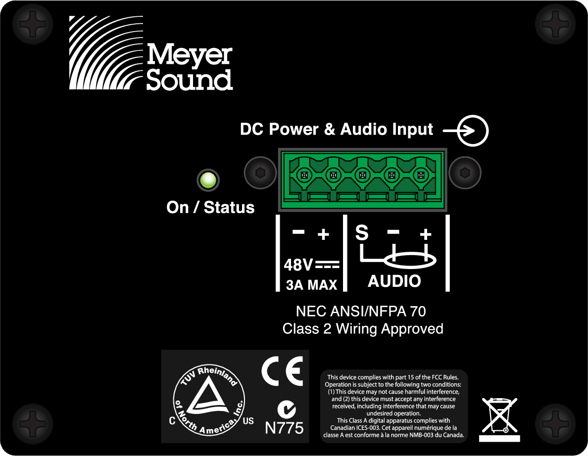 |
Single-Channel Input Connector (HMS-5, HMS-10, and HMS-12)
Single-channel HMS loudspeakers ship with one Phoenix 5-pin female cable mount connector for assembling loudspeaker cables. A single composite cable (such as Belden 1502 or equivalent) can be used to route DC power and balanced audio to the HMS loudspeaker. For more information, see Belden 1502 Cable (or Equivalent) and Assembling Loudspeaker Cables.
Caution
When wiring HMS loudspeaker cables, it is extremely important that each pin be wired correctly. Make sure the 48 V DC from the external power supply is wired directly (and only) to the 48 V DC pins on the loudspeaker connector, and that the polarity is observed (negative to negative, positive to positive) to avoid damage to the loudspeaker. In addition, make sure that audio pins are wired correctly; polarity reversals for audio signals affect system performance.
Dual-Channel Input Connectors (HMS-15)
The HMS-15 loudspeaker receives DC power and balanced audio from two Phoenix 5-pin male Input connectors. Each connector includes two pins for DC power (positive and negative) and three pins for balanced audio (positive, negative, and shield). The pins are clearly labeled on the HMS-15 user panel. To function properly, the HMS-15 requires an MPS-488HP IntelligentDC power supply (two channel outputs per loudspeaker). The MPS-488HP can power up to four HMS-15 loudspeakers.
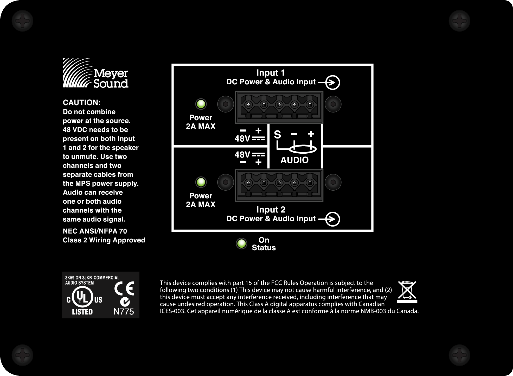 |
Dual-Channel Input Connectors (HMS-15)
The HMS-15 must be connected to a channel output pair (1–2, 3–4, 5–6, or 7–8) of the MPS-488HP using two separate composite cables. When successfully connected and receiving the required voltage, both Input LEDs for the HMS-15 turn solid green. Identical audio signals can be sent to the two inputs with no additional gain and no adverse effect. Sending different audio signals to the two inputs is not recommended and could cause one signal to be heard in the background.
HMS-15 loudspeakers ship with two Phoenix 5-pin female cable mount connectors for assembling loudspeaker cables. Separate composite cables (such as Belden 1502 or equivalent) must be used to route DC power and balanced audio to the two inputs for the HMS-15 loudspeaker. For more information, see Belden 1502 Cable (or Equivalent) and Assembling Loudspeaker Cables.
Note
If the HMS-15 does not sense power from both inputs (both Input LEDs lit) then it will not output audio.
Caution
When wiring HMS loudspeaker cables, it is extremely important that each pin be wired correctly. Make sure the 48 V DC from the external power supply is wired directly (and only) to the 48 V DC pins on the loudspeaker connector, and that the polarity is observed (negative to negative, positive to positive) to avoid damage to the loudspeaker. In addition, make sure that audio pins are wired correctly; polarity reversals for audio signals affect system performance.
Current Draw and Cable Requirements for HMS Loudspeakers
DC current draw for HMS loudspeakers is dynamic and fluctuates as operating levels change. Cabling between HMS loudspeakers and their external power supply adds resistance and hence causes a voltage drop at the loudspeakers. Because lower DC voltages compromise amplifier performance (peak SPL), and in some cases frequency response, cable resistance should be kept to a minimum.
Cable Gauge and Lengths
Cable lengths up to 150 feet between HMS loudspeakers and their external power supply are supported with only 1 dB of peak SPL loss using 18 AWG wire. Longer cable lengths are possible with heavier gauge wires, as shown in the tables below.
Cable Gauge | Resistance (Ohms/ft) | Approximate Max. Length |
|---|---|---|
12 AWG | 0.0016 | 600 ft |
14 AWG | 0.00253 | 375 ft |
16 AWG | 0.00402 | 237 ft |
18 AWG | 0.00636 | 150 ft |
20 AWG | 0.01008 | 87 ft |
Resistance (Ohms/ft) | The USW-112P compact narrow subwoofer's compact rectangular enclosure and slanted connector panel enable flushmounting of the cabinet against wall surfaces, reducing required installation depth to 12 inches, including connectors. | |
|---|---|---|
2.50mm2 | 0.0052 | 157m |
1.50mm2 | 0.01076 | 87m |
1.00mm2 | 0.02087 | 45m |
0.75mm2 | 0.03307 | 27m |

Caution
When wiring HMS loudspeaker cables, it is extremely important that each pin be wired correctly. Make sure the 48V DC from the external power supply is wired directly (and only) to the 48V DC pins on the loudspeaker connector, and that the polarity is observed (negative to negative, positive to positive) to avoid damage to the loudspeaker. In addition, make sure that audio pins are wired correctly; polarity reversals for audio signals affect system performance.
Note
For more information on cable assembly, refer to Assembling Loudspeaker Cables.
For a complete list of available cables and cable accessories from Meyer Sound, refer to HMS Accessories.
Calculating the Maximum Cable Length
The maximum cable length for an HMS loudspeaker can be calculated with the following formula:
maximum length = 2 ohms / (2 * cable resistance)
For example, the maximum length of an 18 AWG cable with a resistance of 0.00636 is 157.2 feet (2 / (2 * 0.00636)).
Belden 1502 Cable (or equivalent)
The most convenient method of wiring HMS loudspeaker cables is with a multiconductor cable such as Belden1502, which has dedicated conductors for DC power and balanced audio in a single jacket. When wiring loudspeaker cables with Belden1502 (or equivalent), use the conventions in the table below. The red and black wires are 18AWG, thicker than the other three wires, and should be used for DC power (cable lengths up to 150 feet are possible with just 1dB of peak SPL loss). The blue, white, and shield drain wires should be used for audio.
 |
Belden1502 Composite Cable
Wire | Signal | Gauge |
|---|---|---|
White | Audio signal (+) | 22 AWG |
Blue | Audio signal (–) | 22 AWG |
Shield drain | Audio shield | 24 AWG |
Red | DC power (+) | 18 AWG |
Black | DC power (–) | 18 AWG |
Caution
When wiring HMS loudspeaker cables, it is extremely important that each pin be wired correctly. Make sure the 48V DC from the external power supply is wired directly (and only) to the 48V DC pins on the loudspeaker connector, and that the polarity is observed (negative to negative, positive to positive) to avoid damage to the loudspeaker. In addition, make sure that audio pins are wired correctly; polarity reversals for audio signals affect system performance.
Note
For more information on cable assembly, refer to Assembling Loudspeaker Cables.
For a complete list of available cables and cable accessories from Meyer Sound, refer to HMS Accessories.
Long Cable Runs with Separate Cable for DC Power and Audio
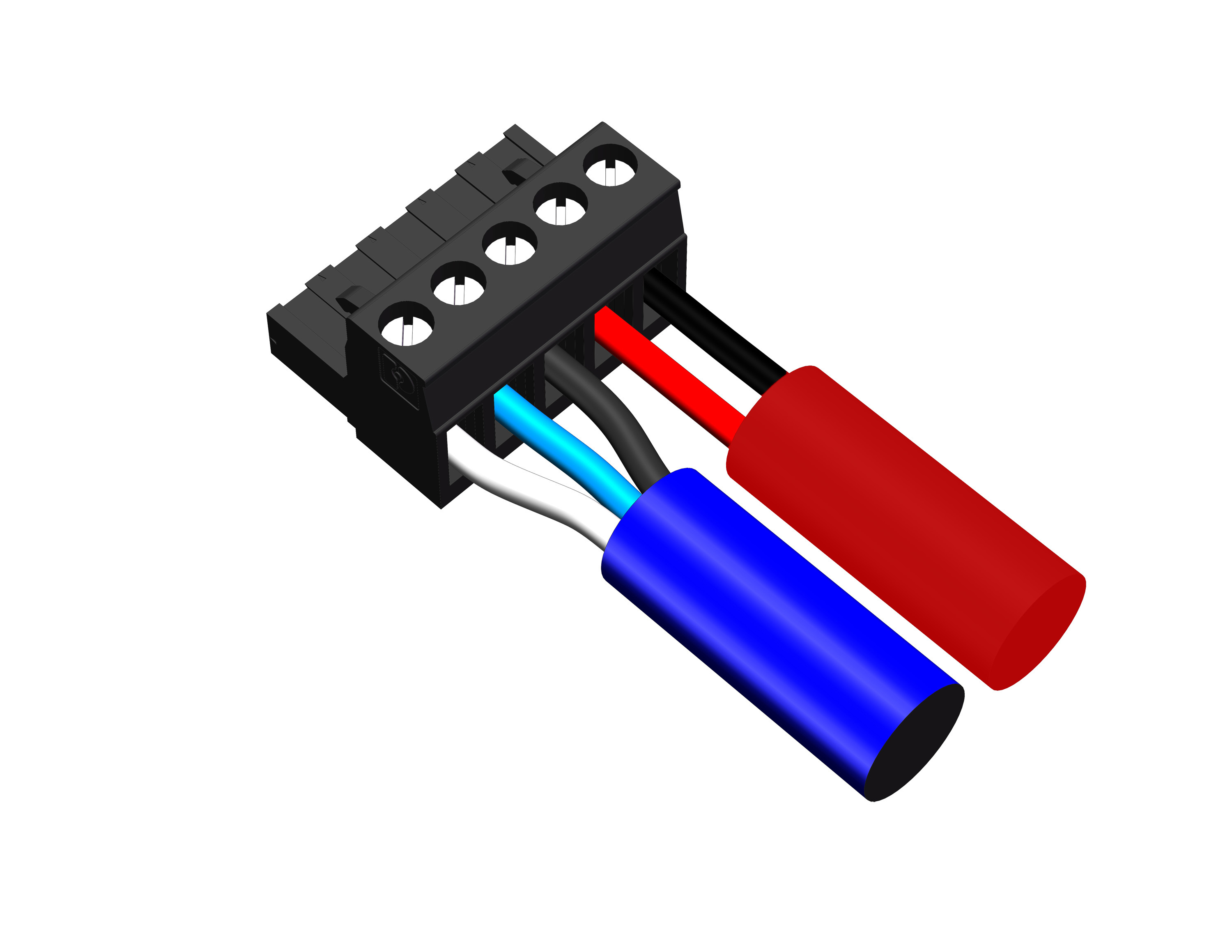
For installations where Belden1502 is not feasible, or for installations that require cable runs longer than 150 feet, you can use separate cables for DC power and balanced audio: a large-gauge cable for DC and a high-quality, balanced audio cable for audio. The separate cables attach to the Phoenix connector at the loudspeaker as shown in Figure. Cable runs longer than 150 feet for DC power require heavier gauge wires (larger than 18AWG); for more information, see Cable Gauge and Lengths.
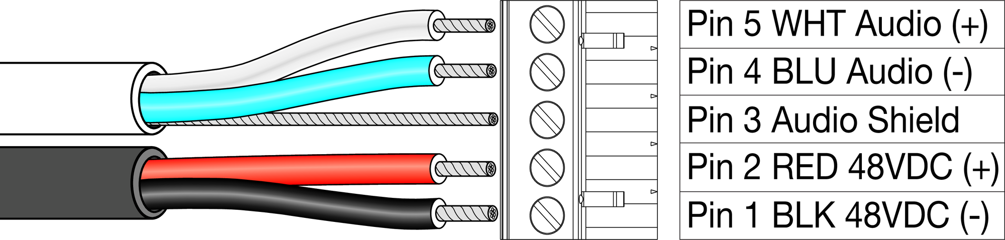 |
Separate Cables for DC Power and Balanced Audio
On/Status LED
The HMS user panel includes an On/Status LED that indicates whether the loudspeaker is operating normally (green), limiting or overheating (yellow), or clipping (red).
Note
The HMS-15 also includes two Input LEDs that indicate, when solid green, when the inputs are receiving voltage from the MPS-488HP.
Normal Operation (Green)
When powering on the HMS loudspeaker, the following startup events occur and are indicated by the On/Status LED:
The On/Status LED flashes multiple colors during its power-on sequence.
The LED turns solid green, indicating the power-on sequence has completed and the loudspeaker is ready to reproduce audio.
The LED remains green but is dimmed to eliminate any undesired glow in darkened theatres.
Caution
If after the power-on sequence the On/Status LED does not turn solid green (instead flashes multiple colors or stays solid red) and the HMS loudspeaker does not output audio, the loudspeaker has encountered an error and may need to be serviced. Contact Meyer Sound Technical Support.
CAUTION:
Note
All three LEDs for the HMS-15 (Input 1, Input 2, and On/Status) must turn solid green before it will output audio. If some or all of the HMS-15 LEDs remain unlit, or not green, verify the cabling to the MPS-488HP.
Limiting (Yellow)
The On/Status LED turns yellow to indicate limiting. When the LED is solid yellow, limiting is engaged for the high-frequency channel. When the LED flashes yellow (on and off), limiting is engaged for the low-frequency channel.
When engaged, limiting not only protects the drivers but also prevents signal peaks from causing excessive distortion in the amplifier channels, thereby preserving headroom and maintaining smooth frequency response at high levels. When levels return to normal, below the limiter thresholds, limiting ceases and the On/Status LED returns to green.
The HMS loudspeaker performs within its acoustical specifications at normal temperatures when the On/Status LED is green, or when limiting is not continuous. If limiting activity is continuous, the loudspeaker is nearing the limits of its operating capabilities where:
Increases to the input level have no effect
Distortion increases due to clipping
Drivers are subjected to excessive heat and excursion, thereby compromising their lifespan
Caution
Continuous limiting indicates that a safe, optimum level has been exceeded. If the HMS loudspeakers in a cinema installation begin to limit before reaching the desired SPL, consider adding more units to the system.
Operating Temperature
The On/Status LED also turns solid yellow when the HMS loudspeaker’s internal temperature reaches a certain level, indicating the unit is reaching its maximum heat dissipation. When the On/Status LED is yellow, a reduction in SPL is recommended. While the loudspeaker will continue to operate while the LED is yellow, the limiter threshold is lowered (causing the output level to also be reduced) to prevent the loudspeaker from overheating. When the loudspeaker’s internal temperature returns to a normal level, the On/Status LED returns to green and the limiter threshold returns to normal.
Amplifier Cooling
HMS loudspeakers rely solely on natural convection for cooling from air flowing over their heat sinks. The efficient amplifier and heat sink design keeps temperatures low, even when units are operated at high ambient temperatures and driven continuously at high output levels.
Clipping on Input (Red)
The On/Status turns red when the loudspeaker’s input stage clips, causing the amplifier to overload. When the On/Status LED is red, the source level should be reduced to avoid distortion and to avoid overloading the amplifier.
Caution
If the On/Status LED turns solid red and the loudspeaker continues to output audio, though at reduced levels, the loudspeaker’s voltage may have dropped below 25 V DC. When these conditions are encountered, operation of the loudspeaker should cease and its power supply and cabling should be verified.
Pad Switch (HMS-10 only)
The HMS-10 user panel includes a Pad switch that, when enabled, reduces the loudspeaker’s internal gain by 7.5dB, thereby lowering the loudspeaker’s noise floor. This reduces noise generated from audio sources upstream from the loudspeaker and is especially useful for close proximity listening.
 |
HMS-10 Pad Switch
Note
When the Pad switch is enabled (set to Pad), to achieve the linear peak SPL for the loudspeaker, the gain for the processor driving the loudspeaker must be increased by 7.5dB.
Powering HMS Loudspeakers
MPS-488HP IntelligentDC High-power Eight-channel Power Supply
HMS loudspeakers require an external MPS-488HP IntelligentDC power supply. The single-space 19-inch rack unit distributes DC power and balanced audio to up to eight HMS-5, HMS-10, or HMS-12 loudspeakers, or up to four HMS-15 loudspeakers. Composite multiconductor cables, such as Belden 1502 or equivalent, can deliver both DC power and balanced audio to loudspeakers at cable lengths up to 150 feet with just 1 dB of loss in peak SPL using 18 AWG wire. Longer cable runs are possible with heavier gauge wires. Meyer Sound’s RMS remote monitoring system is optionally available for the MPS-488HP.

MPS-488HP IntelligentDC Power Supply
Caution
Disconnect the mains plug or power off the MPS-488HP before disconnecting its power cord.
Tip
For complete information on using the MPS-488HP IntelligentDC power supply, refer to the MPS-488HP Operating Instructions (PN 05.205.005.01) available at meyersound.com/documents.
Powering HMS Loudspeakers
Note
The MPS-488HP can power up to eight single-channel HMS loudspeakers (HMS-5, HMS-10, and HMS-12), or up to four dual-channel HMS-15 loudspeakers.
Power off the MPS-488HP.
Connect audio sources (from a mixer or processor) to the MPS-488HP channel inputs. Use balanced XLR cables.
Use the MPS-488HP Link switches to route channel inputs to the desired channel outputs. For information about the MPS-488HP Link switches, refer to the MPS-488HP Operating Instructions.
Connect HMS loudspeakers to the MPS-488HP channel outputs. Use composite cables (such as Belden1502 or equivalent) wired for both DC power and balanced audio and outfitted with the appropriate connectors.
To power single-channel HMS loudspeakers (HMS-5, HMS-10, and HMS-12), connect each loudspeaker to a single-channel output with a single composite cable. The MPS-488HP can power up to eight single-channel HMS loudspeakers.
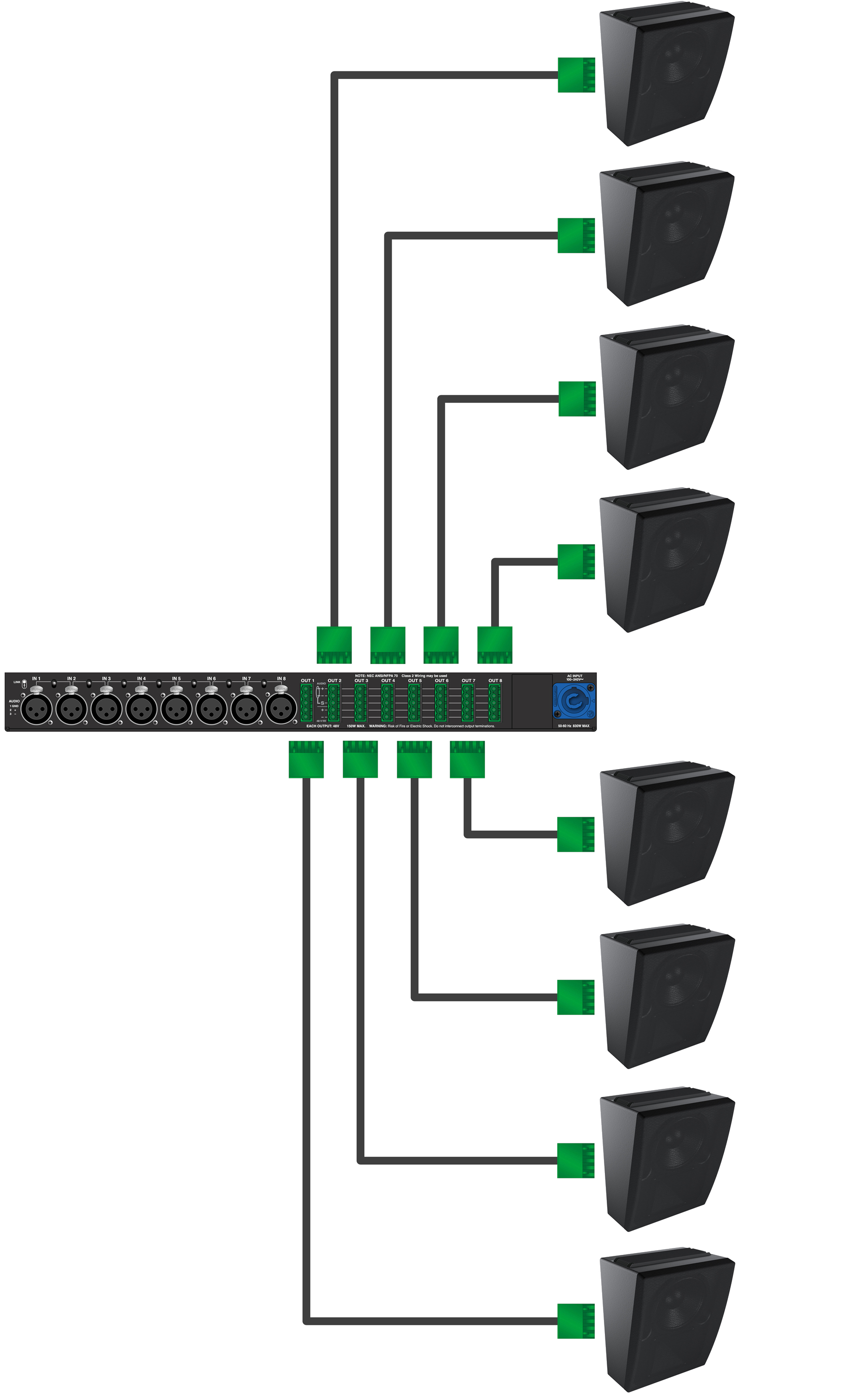
MPS-488HP with Eight HMS-10 Loudspeakers
To power dual-channel HMS-15 loudspeakers, connect each loudspeaker to a channel output pair (1–2, 3–4, 5–6, or 7–8) with two separate composite cables. The MPS-488HP can power up to four dual-channel HMS-15 loudspeakers.
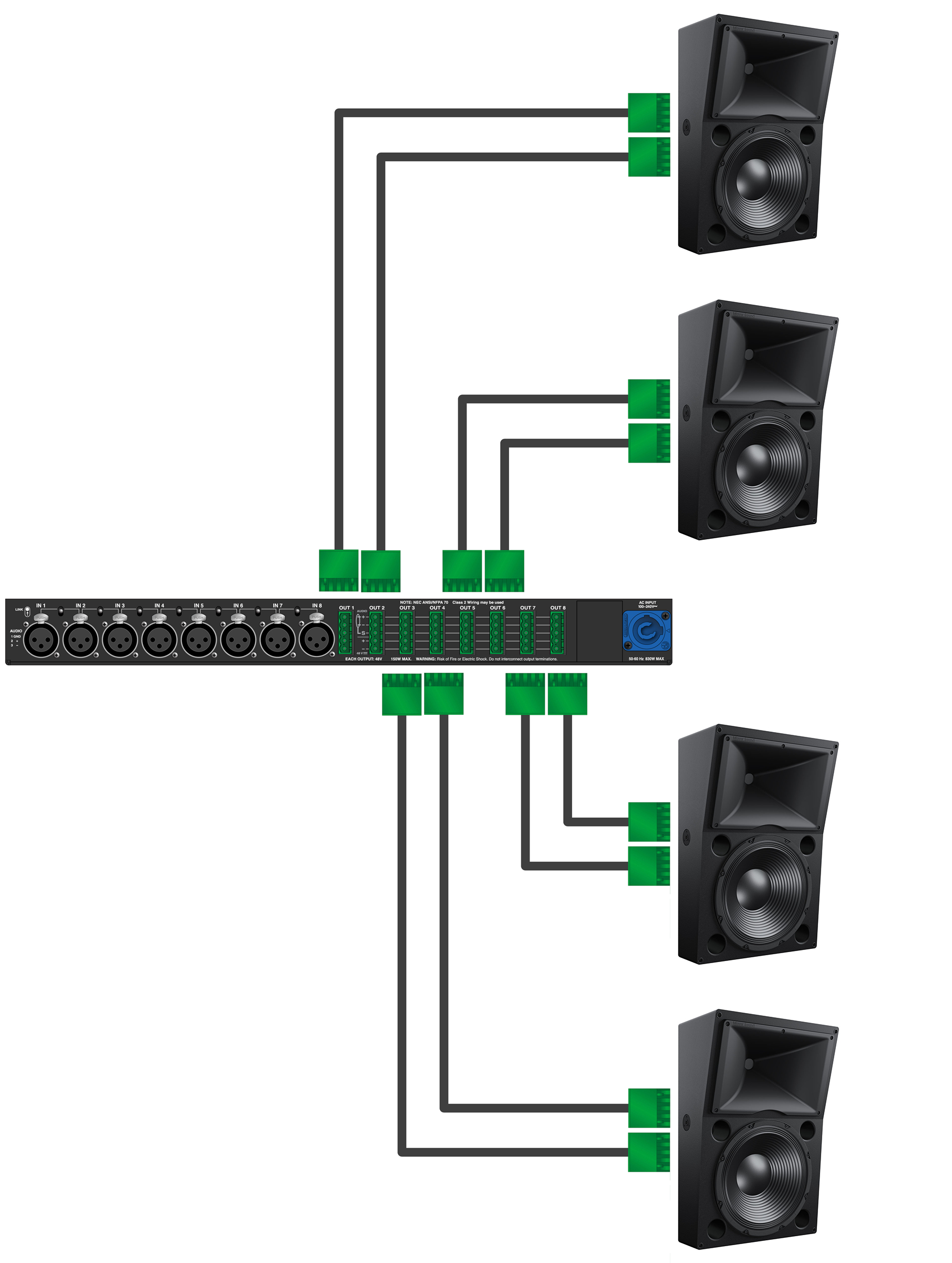
MPS-488HP with Four HMS-15 Loudspeakers
Caution
When powering HMS-15 loudspeakers, you must use two separate composite cables connected to an MPS-488HP channel output pair (1–2, 3–4, 5–6, or 7–8). Do not use a single cable to deliver power to the HMS-15’s two Input connectors. Never, in any manner, combine the signals from two MPS-488HP channel outputs, either at the power supply (source) or the loudspeaker (destination).
Make sure loudspeaker cables are wired correctly. For details on assembling loudspeaker cables, refer to Assembling Loudspeaker Cables.
Tip
You can use separate cables for HMS loudspeaker connections: a 2-conductor cable for DC power and a 3-conductor cable for balanced audio, both attached to a single Phoenix connector on each cable end. This allows you to use a larger gauge for the DC cable so you can achieve longer cable runs (see Long Cable Runs with Separate Cable for DC Power and Audio).
Power on the MPS-488HP and monitor the LEDs on the front panel to verify connections. For information about the MPS-488HP LEDs, refer to the MPS-488HP Operating Instructions.
Monitor the HMS loudspeaker LEDs to verify they are receiving power.
For single-channel HMS loudspeakers (HMS-5, HMS-10, and HMS-12), make sure the On/Status LED turns solid green after powering on the loudspeakers.
For dual-channel HMS-15 loudspeakers, make sure the two Input LEDs and On/Status LED turn solid green after powering on the loudspeakers.
Enable output from the audio sources (from the mixer or processor) connected to the MPS-488HP.
HMS Mounting Options
Important safety considerations
When installing Meyer Sound loudspeakers, always observe the following precautions:
Use all Meyer Sound products in accordance with local, state, federal, and industry regulations. Owners and users must evaluate the reliability of any rigging or mounting method for their application. Rigging loudspeakers requires trained and experienced professionals.
Use mounting and rigging hardware rated to meet or exceed the suspended weight.
Make sure to attach mounting hardware to the building's structural components (studs or joists), and not just to the wall surface. Verify that the building's structure and the anchors used for the installation will safely support the total weight of the mounted loudspeakers.
Use mounting hardware appropriate for the installation surface.
Tighten bolts securely. Meyer Sound recommends using Loctite® on bolt threads and safety cables.
Inspect mounting and rigging hardware regularly. Immediately replace any worn or damaged components.
HMS Mounting Options
The table below list the mounting options available for HMS loudspeakers. All mounting options are rated for mounting a single HMS loudspeaker with a 7:1 safety factor. For more information, refer to the installation instructions included with the mounting hardware.
Model (Part Number) | Features | Maximum Uptilt/Downtilt | Weight | Rated for Overhead Mounting | |
|---|---|---|---|---|---|
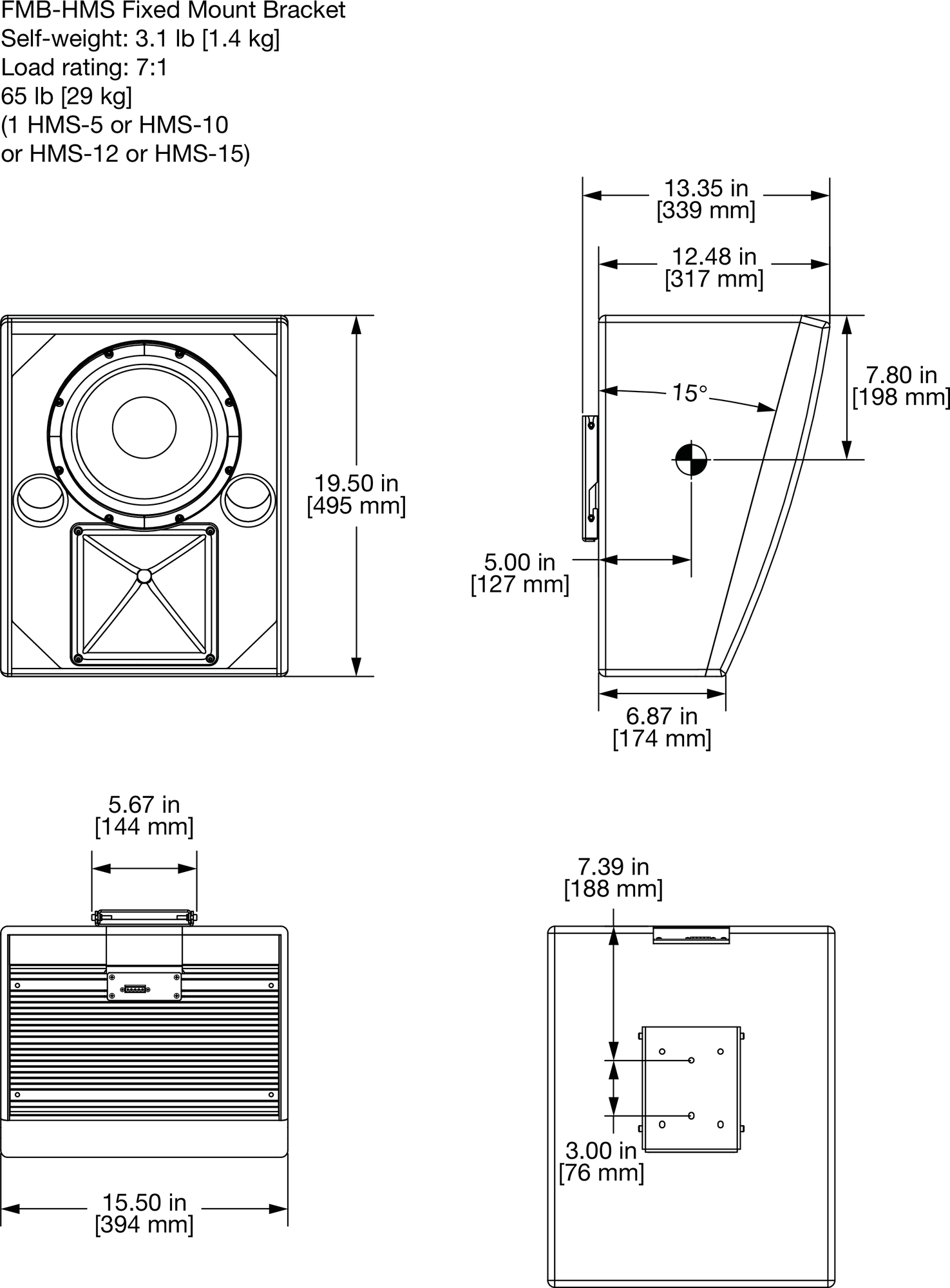
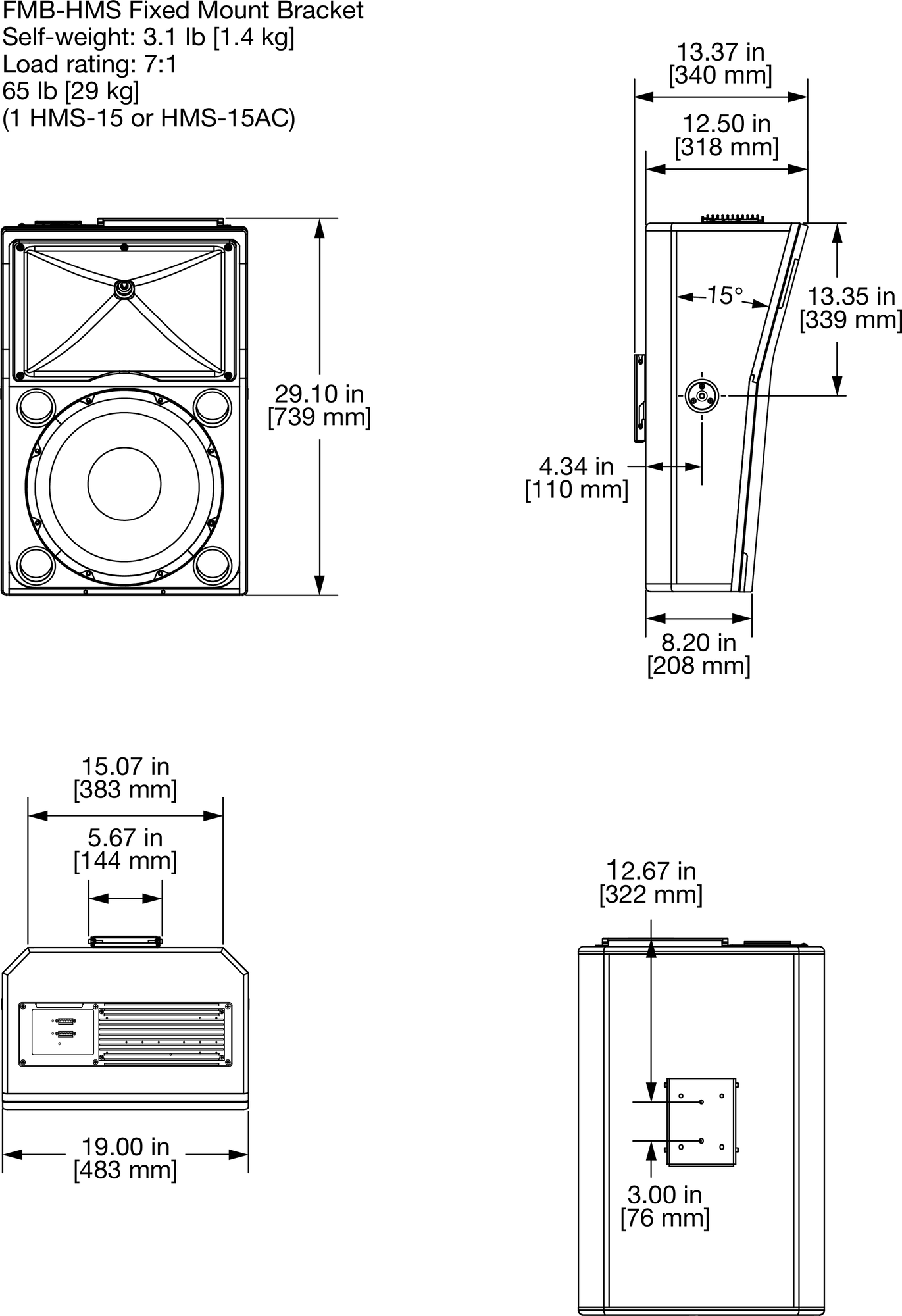
FMB-HMS Fixed Mount Bracket (PN40.198.040.01) 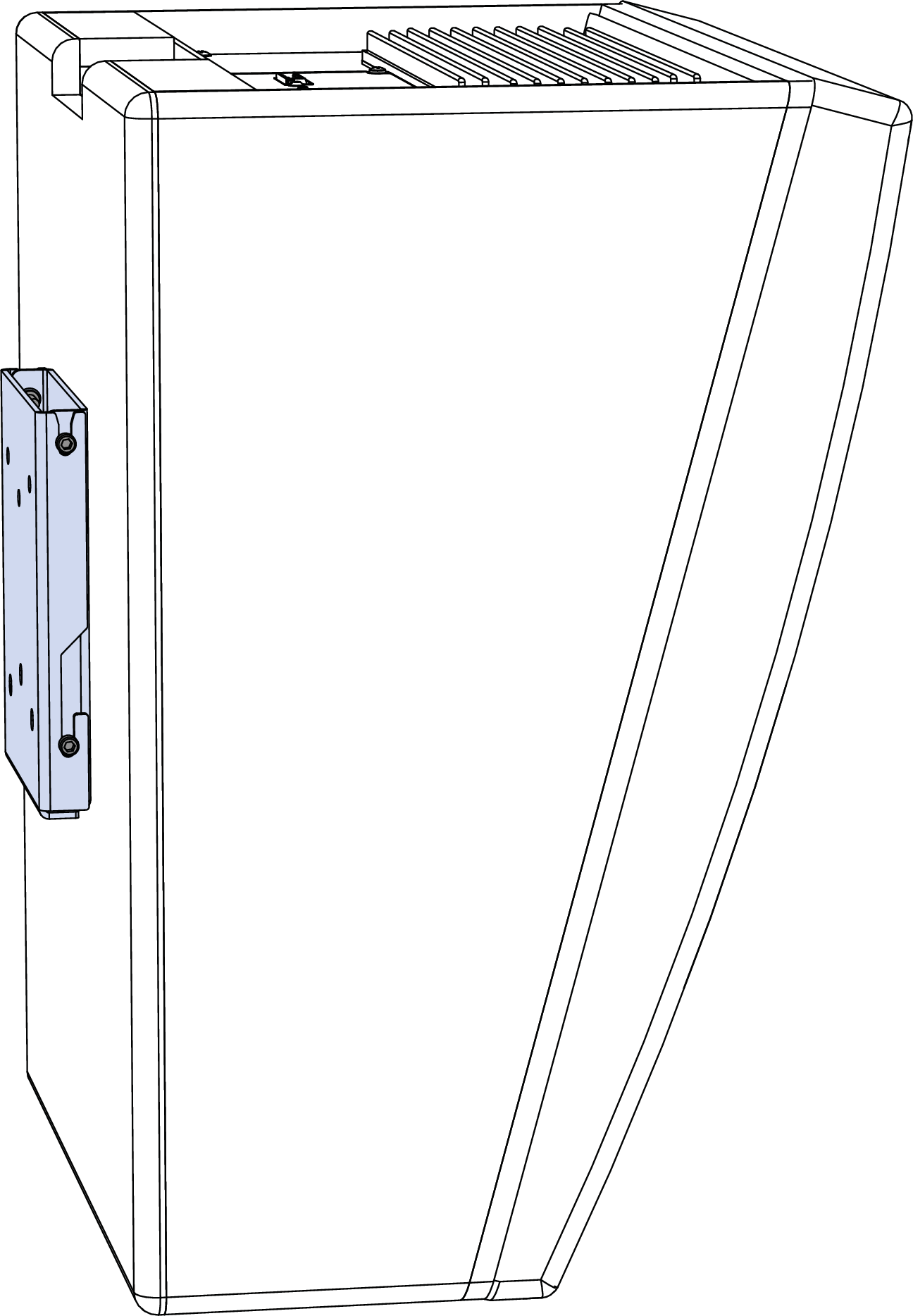 | Mounts HMS loudspeakers (all models) on walls at a fixed 0 degree angle. The fixed bracket mounts cabinets 0.87 inches from the wall. |
| 3.1 lbs (1.4 kg) | No | |
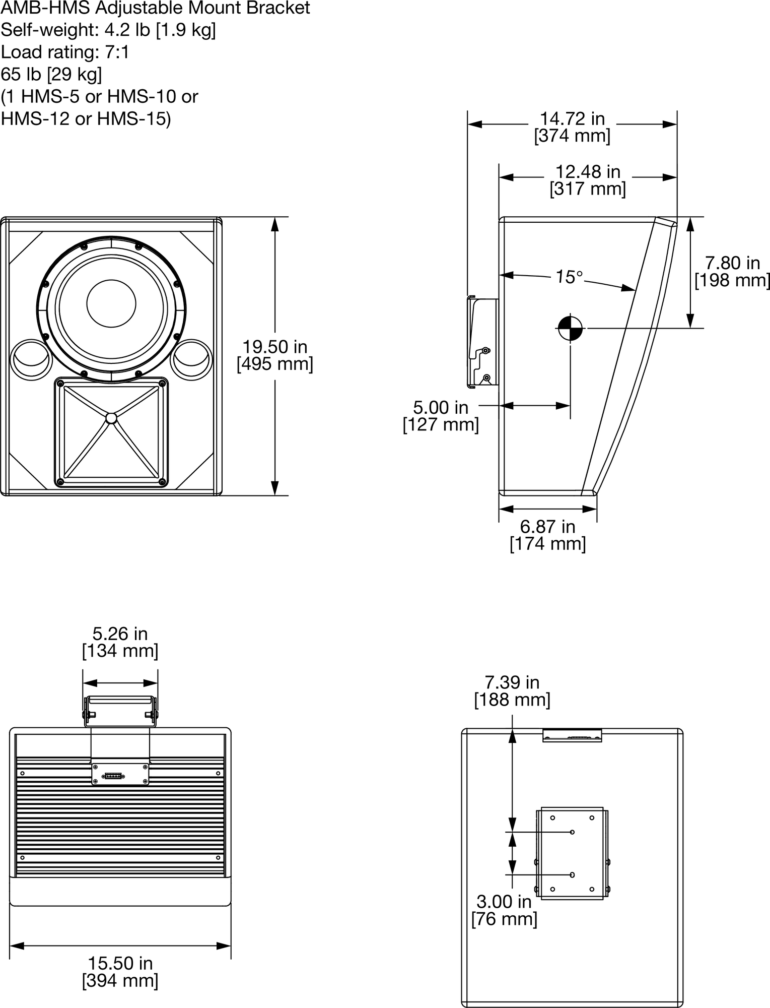
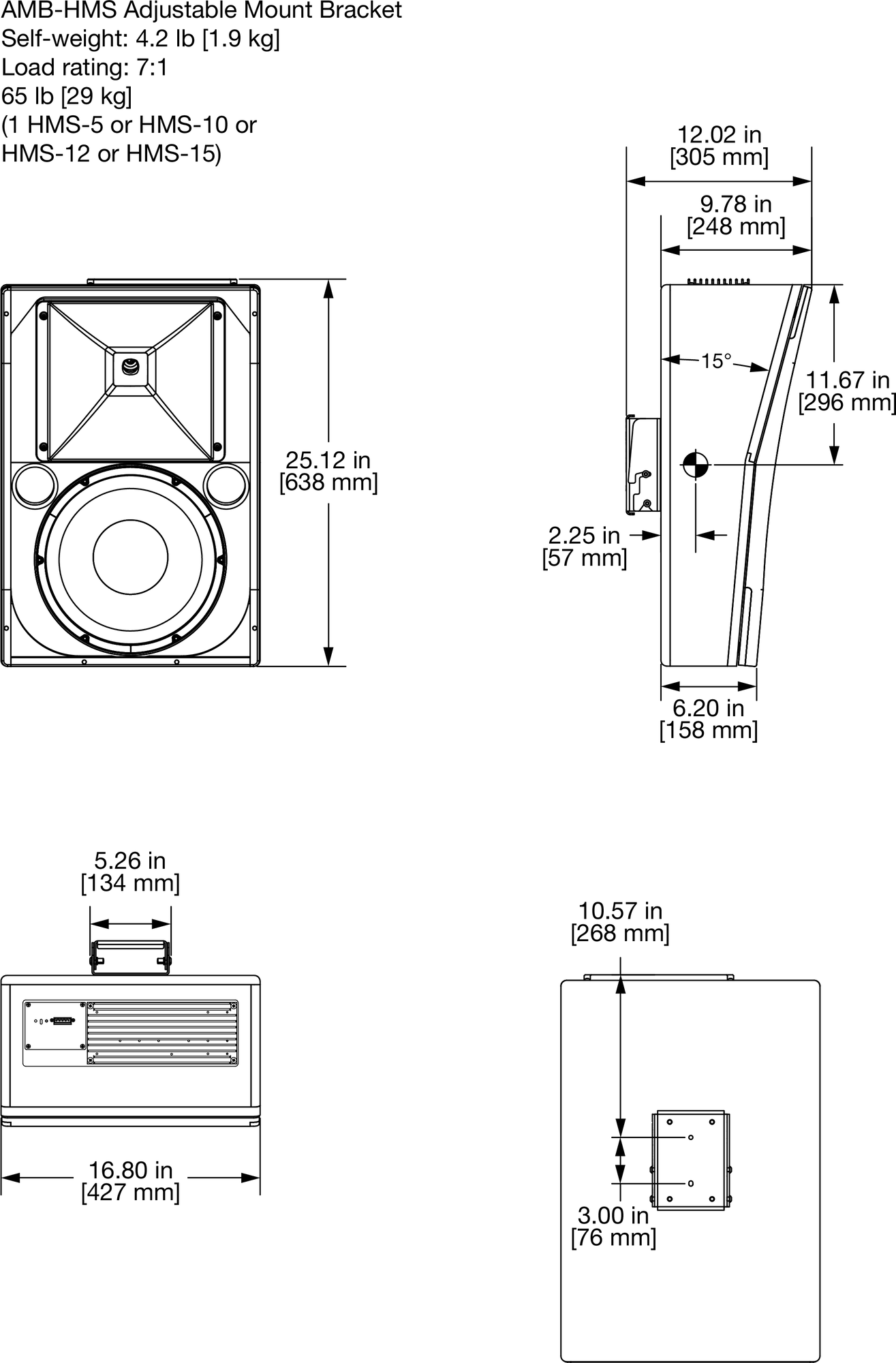
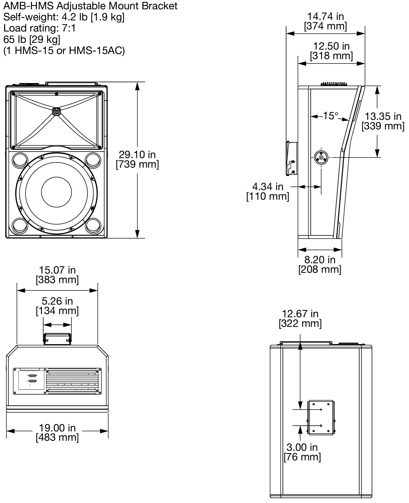
AMB-HMS Adjustable Mount Bracket (PN40.198.040.01) 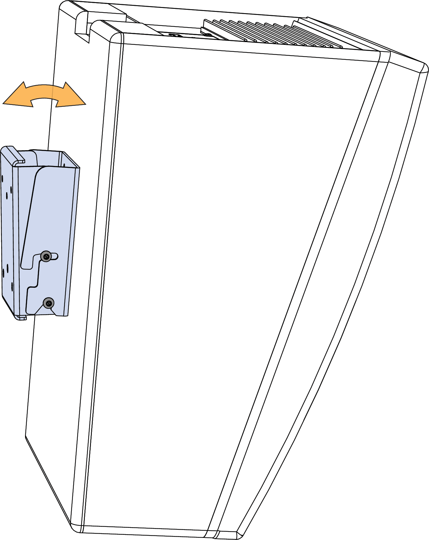 | Mounts HMS loudspeakers (all models) on walls with uptilt or downtilt. The available tilt depends on the HMS loudspeaker model mounted. When installed with no tilt, the bracket mounts cabinets 2.24 inches from the wall. |
NoteWider downtilt may be possible depending on the building’s structural components and mounting surface. | 4.2lbs (1.9kg) | No | |
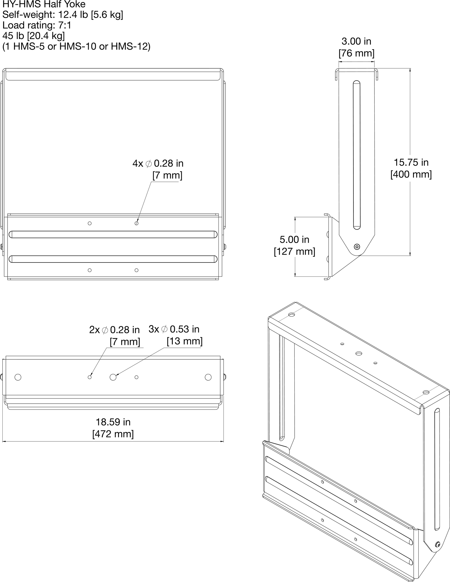
HY-HMS Half Yoke (PN40.227.031.01) 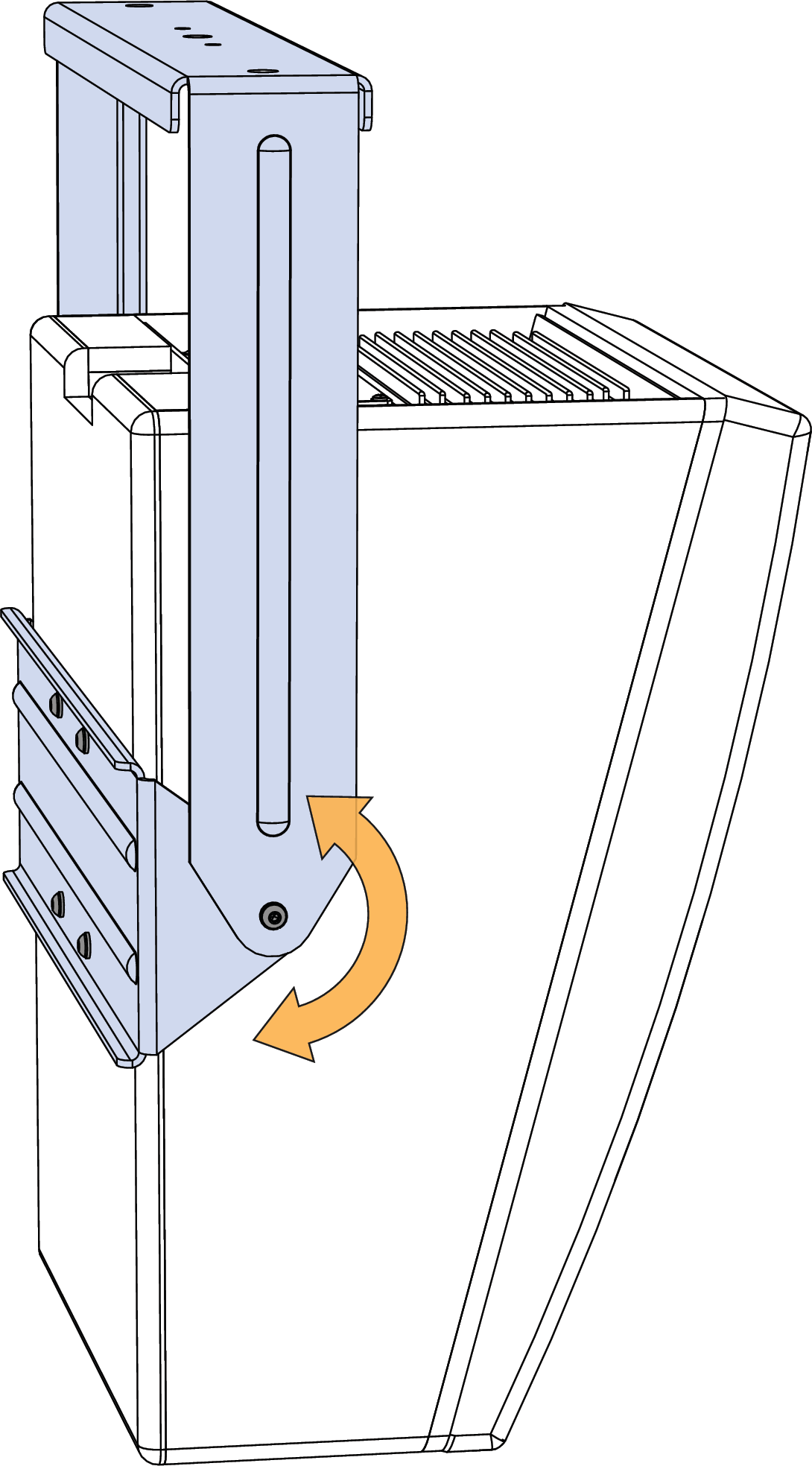 | Suspends HMS-5, HMS-10, and HMS-12 loudspeakers with a full range of tilt (360°). The yoke can attach directly to ceilings or can accept “C” or “G” hanging clamps with standard 1/2-inch or 12mm bolts. |
| 12.4lbs (5.6kg) | Yes | |
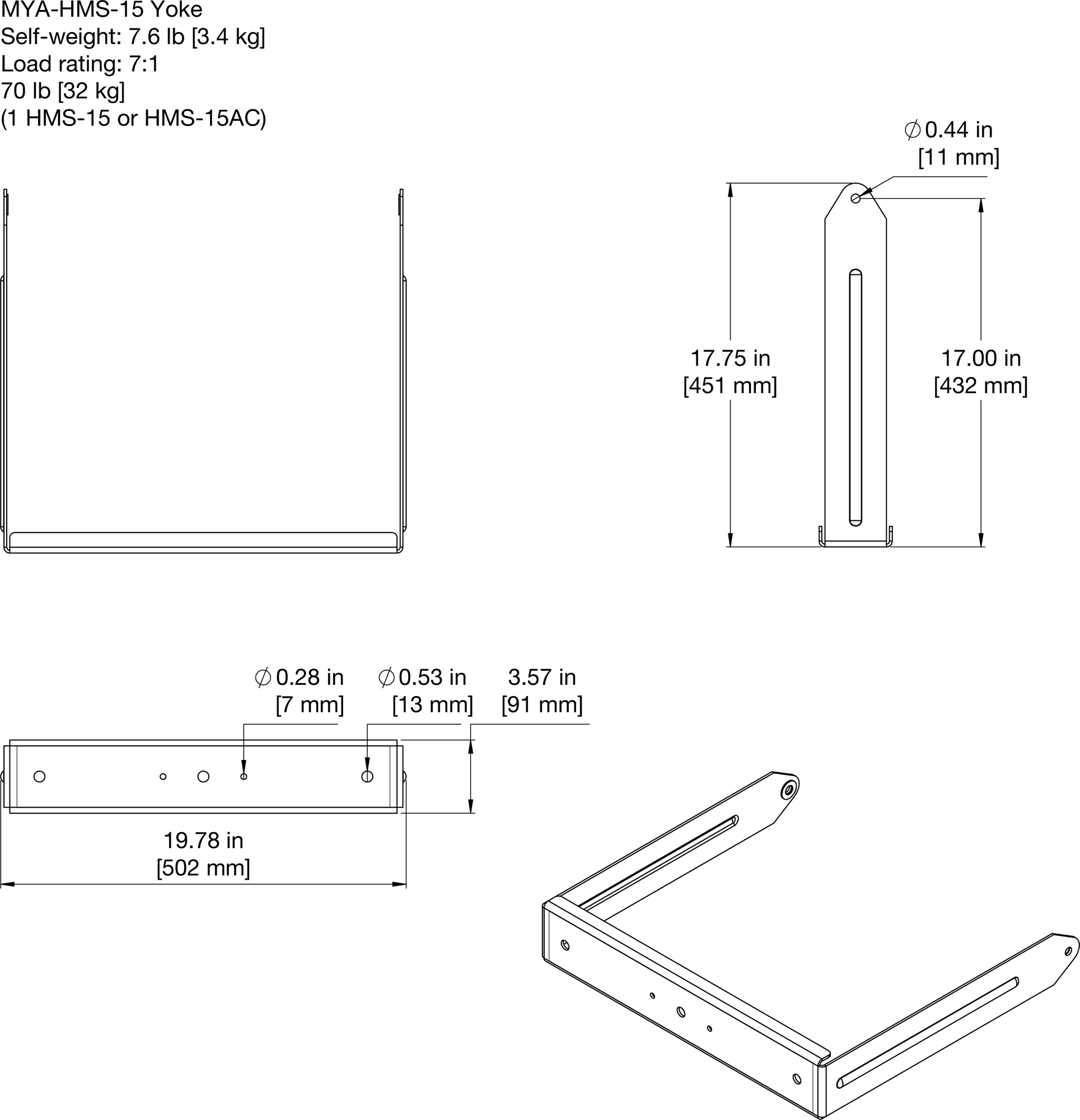
MYA-HMS-15 Yoke (PN40.242.035.01)
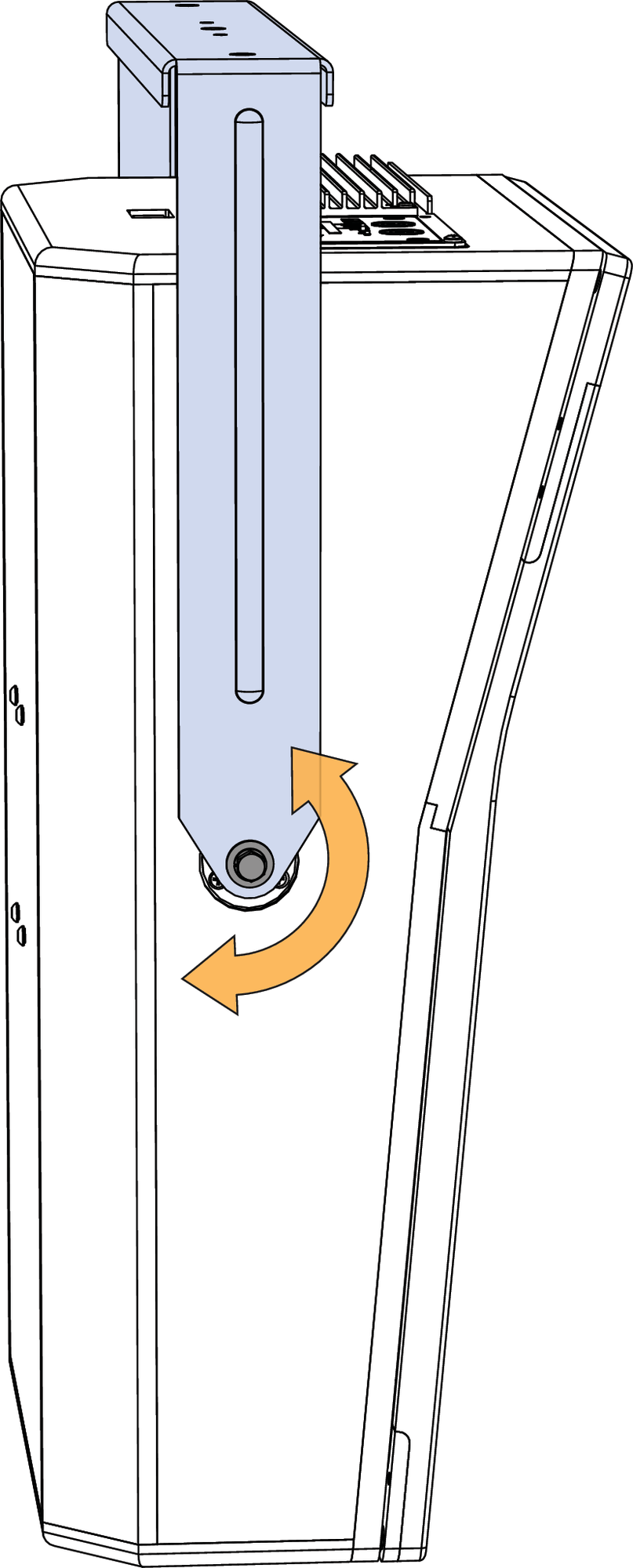
| Suspends HMS-15 and HMS-15AC loudspeakers with a full range of tilt (360°). The yoke can attach directly to ceilings or can accept “C” or “G” hanging clamps with standard 1/2-inch or 12mm bolts. |
| 7.6lbs (3.4kg) | Yes | |
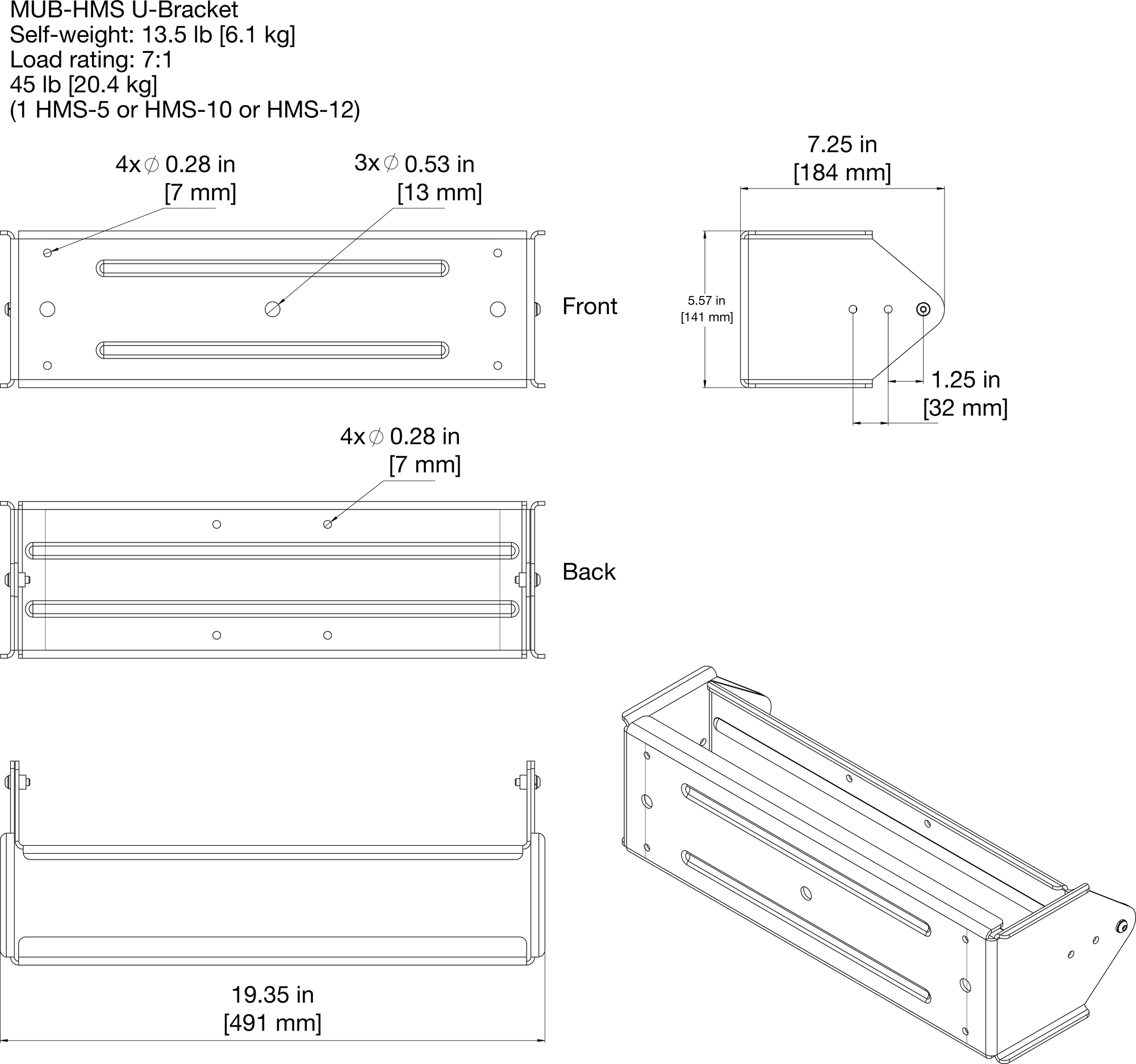
MUB-HMS U-Bracket (PN40.227.032.01) 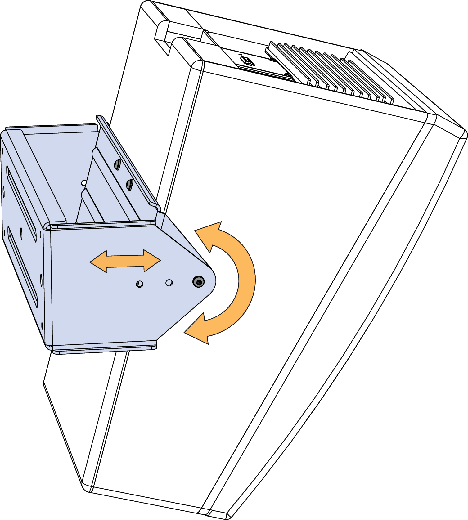 | Mounts HMS-5, HMS-10, and HMS-12 loudspeakers on walls and ceilings with uptilt or downtilt. The U-bracket includes three loudspeaker attachment points for placing the loudspeaker closer or further from the mounting surface. The available tilt is determined by which HMS loudspeaker model is mounted and which attachment points are used. |
| 13.5lbs (6.1kg) | Yes | |
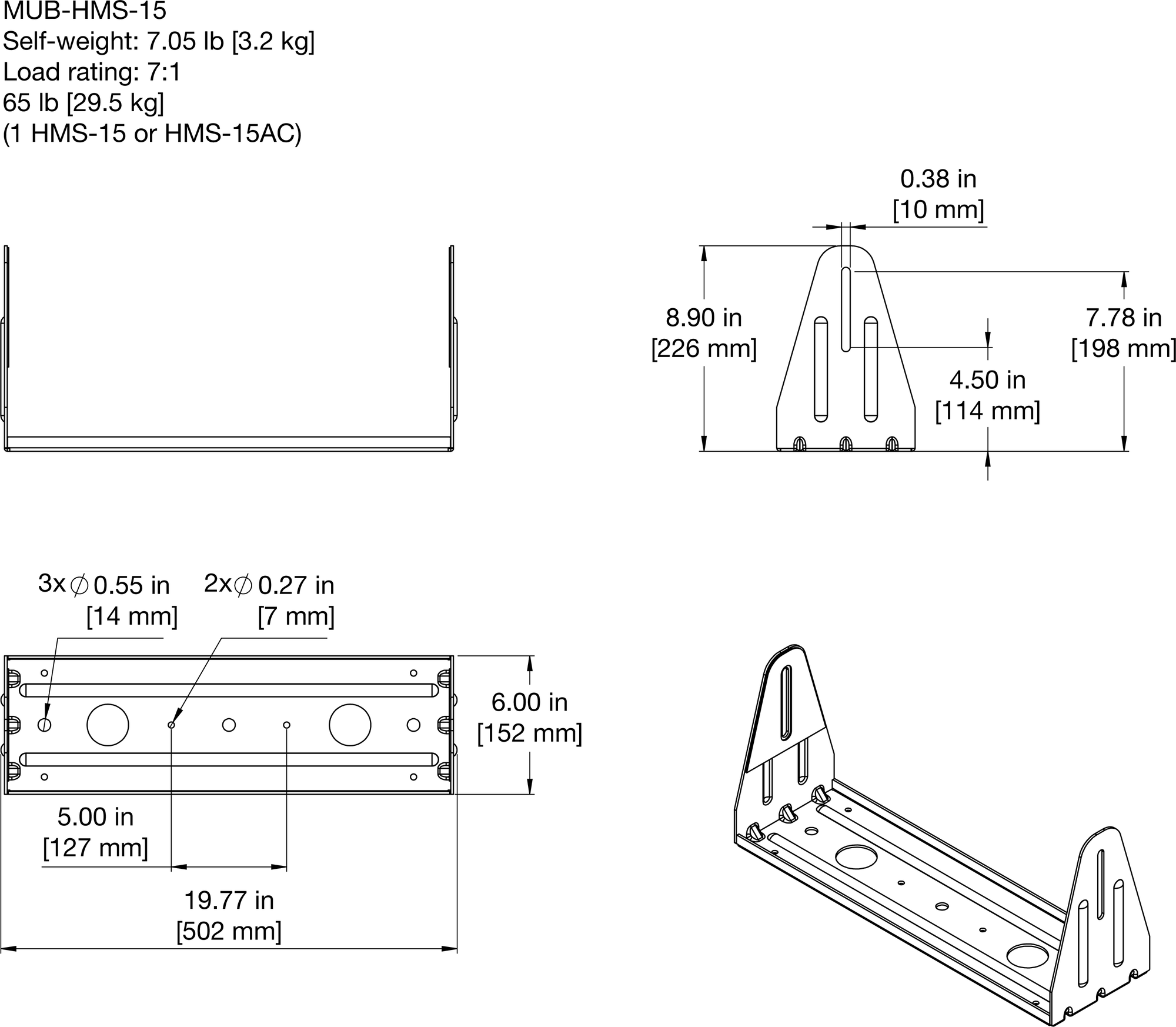
MUB-HMS-15 U-Bracket (PN40.242.025.01) 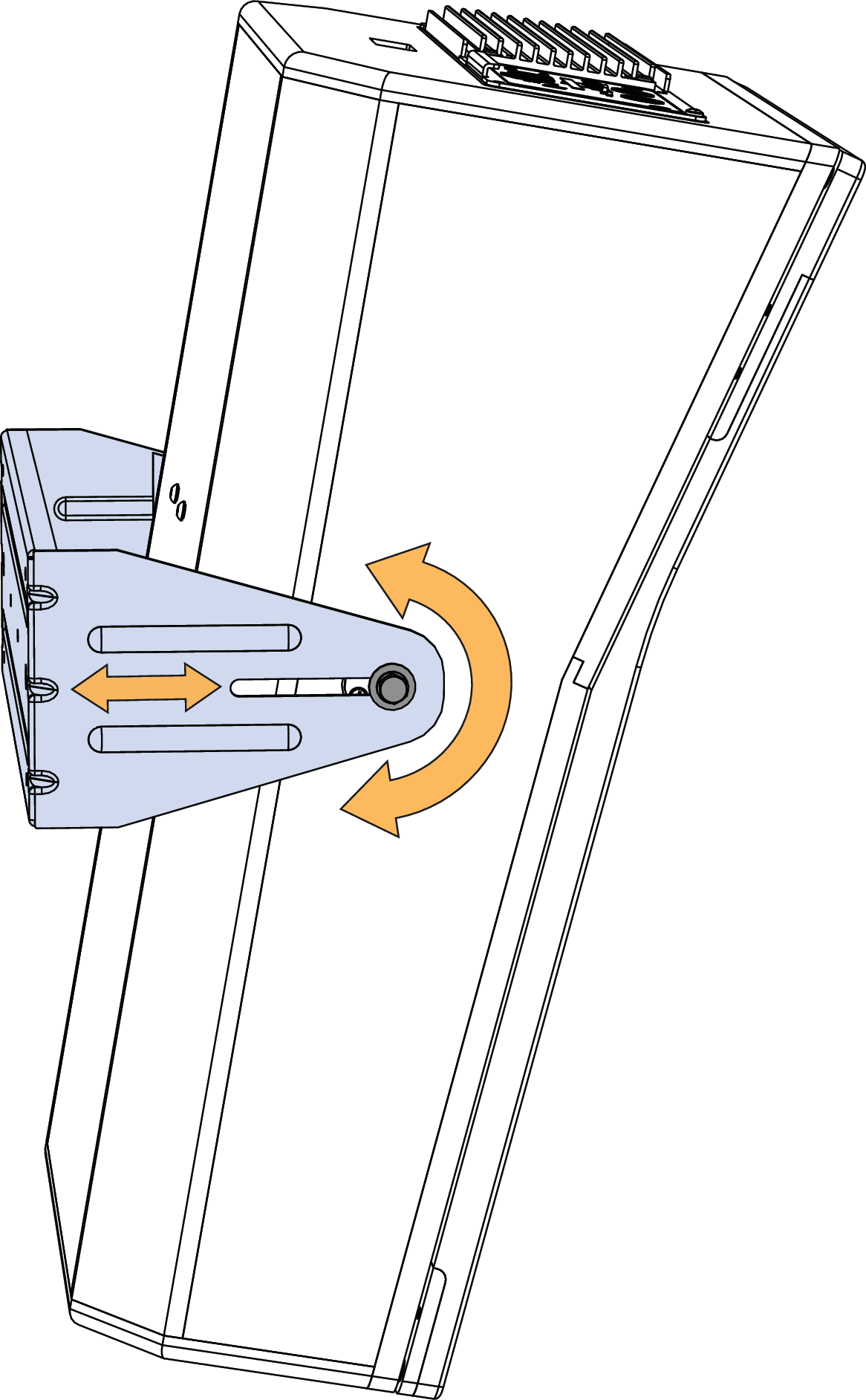 | Mounts HMS-15 and HMS-15AC loudspeakers on walls and ceilings with uptilt or downtilt. The U-bracket includes a loudspeaker attachment slot for placing the loudspeaker closer or further from the mounting surface. The available tilt is determined by how close the loudspeaker is placed to the mounting surface. |
| 7.6lbs (3.4kg) | Yes | |
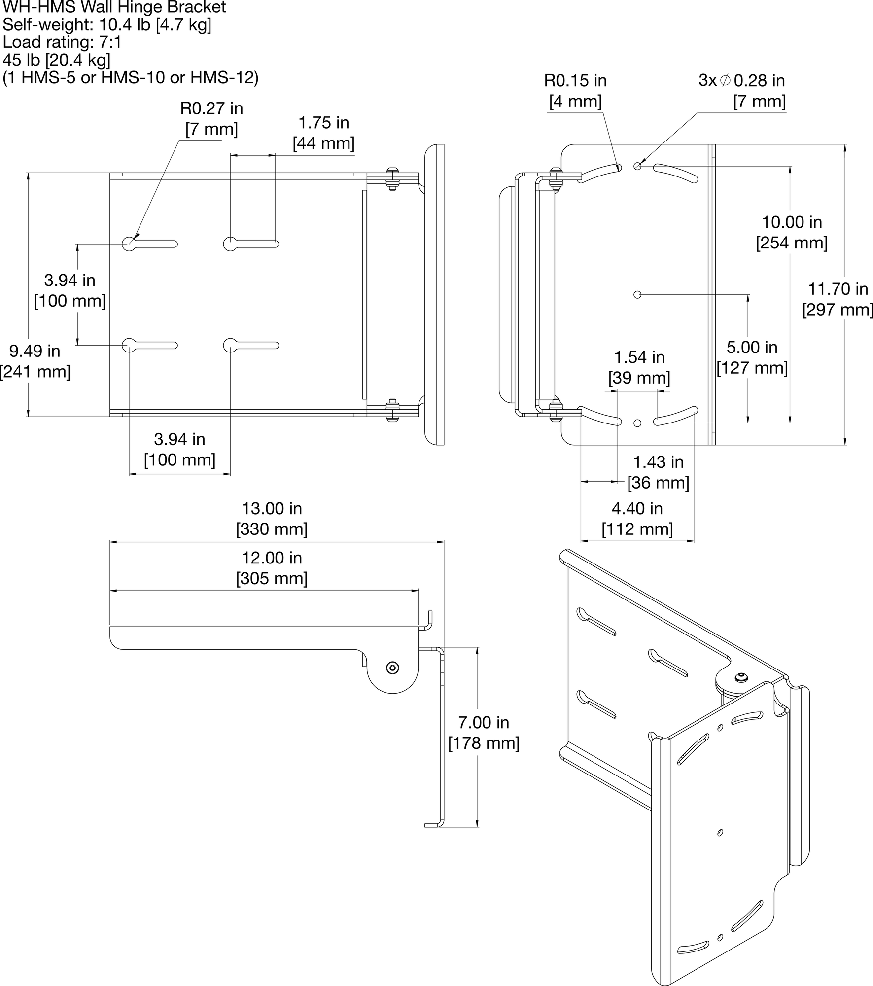
WH-HMS Wall Hinge Bracket (PN40.227.030.01) 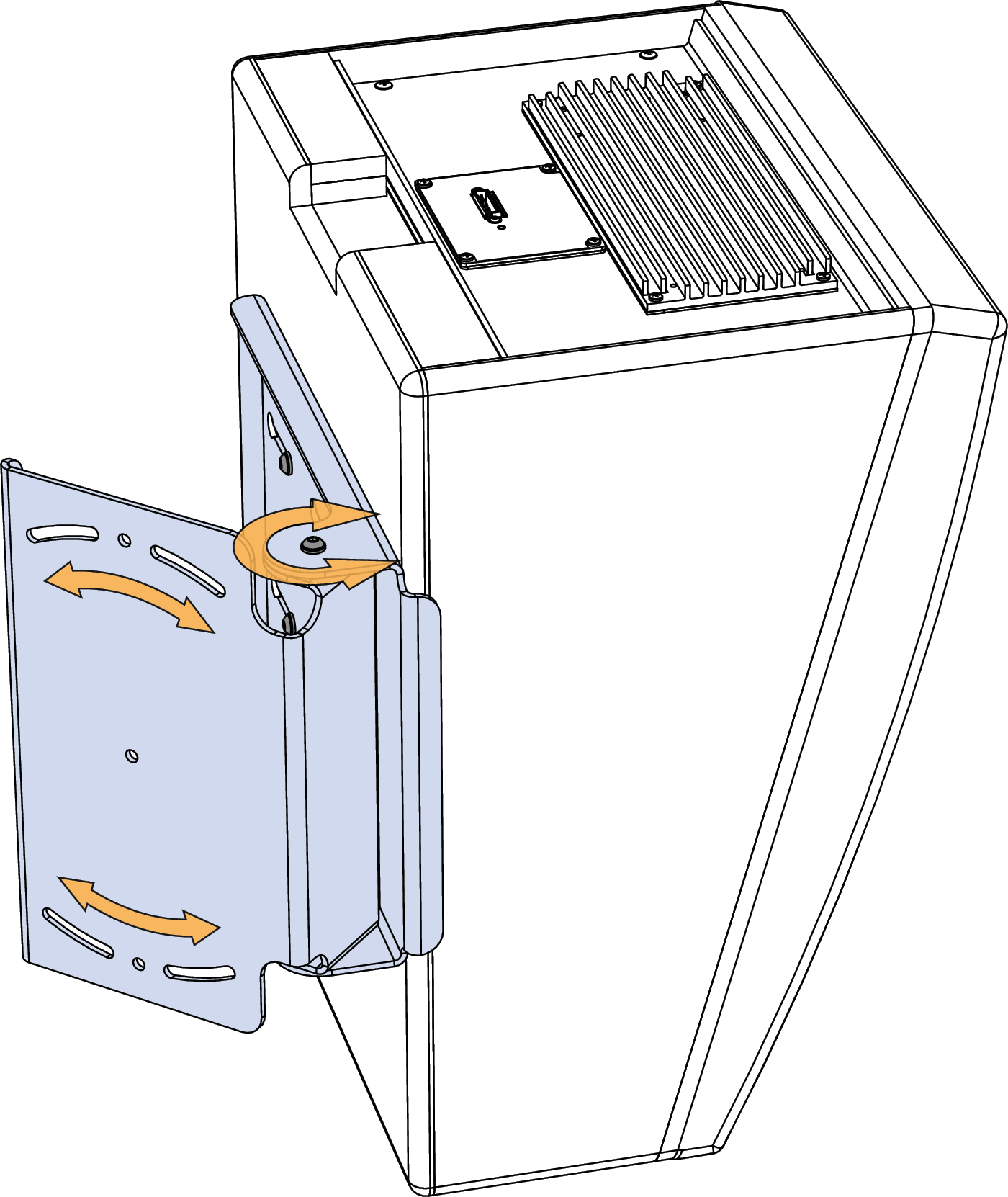 | Mounts HMS-5, HMS-10, and HMS-12 loudspeakers on walls with the capability of aiming them horizontally up to 90° away from the wall. The bracket is symmetrical, allowing it to be rotated 180° so cabinets can be aimed either toward or away from the screen. |
| 10.4lbs (4.7kg) | No |
Caution
When mounting HMS loudspeakers in soffits, allow at least 3 inches above the loudspeaker for the bracket to slide into place. The extra space is also required for ventilation for the loudspeaker’s amplifier and heat sink.
Note
When mounting HMS loudspeakers in soffits, allow sufficient space around the loudspeaker so its coverage pattern is unobstructed by the walls of the soffit.
Removing HMS Grille Frames
If a cinema installation requires it, HMS grille frames can be easily removed. Grille frames for the HMS-5 and HMS-10 are removed by simply unsnapping the corner treeloks and removing the grille. Grille frames for the HMS-12 and HMS-15 include an L-bracket securing them to the bottom of the cabinet, for safety reasons, that must be removed before the grille can be detached.
Removing HMS-12 and HMS-15 Grille Frame
Use a Phillips-head screwdriver to loosen the pan head screw on the bottom front of the cabinet securing the grilleframe’s L-bracket. Slide the L-bracket forward to remove it. Set the L-bracket aside.
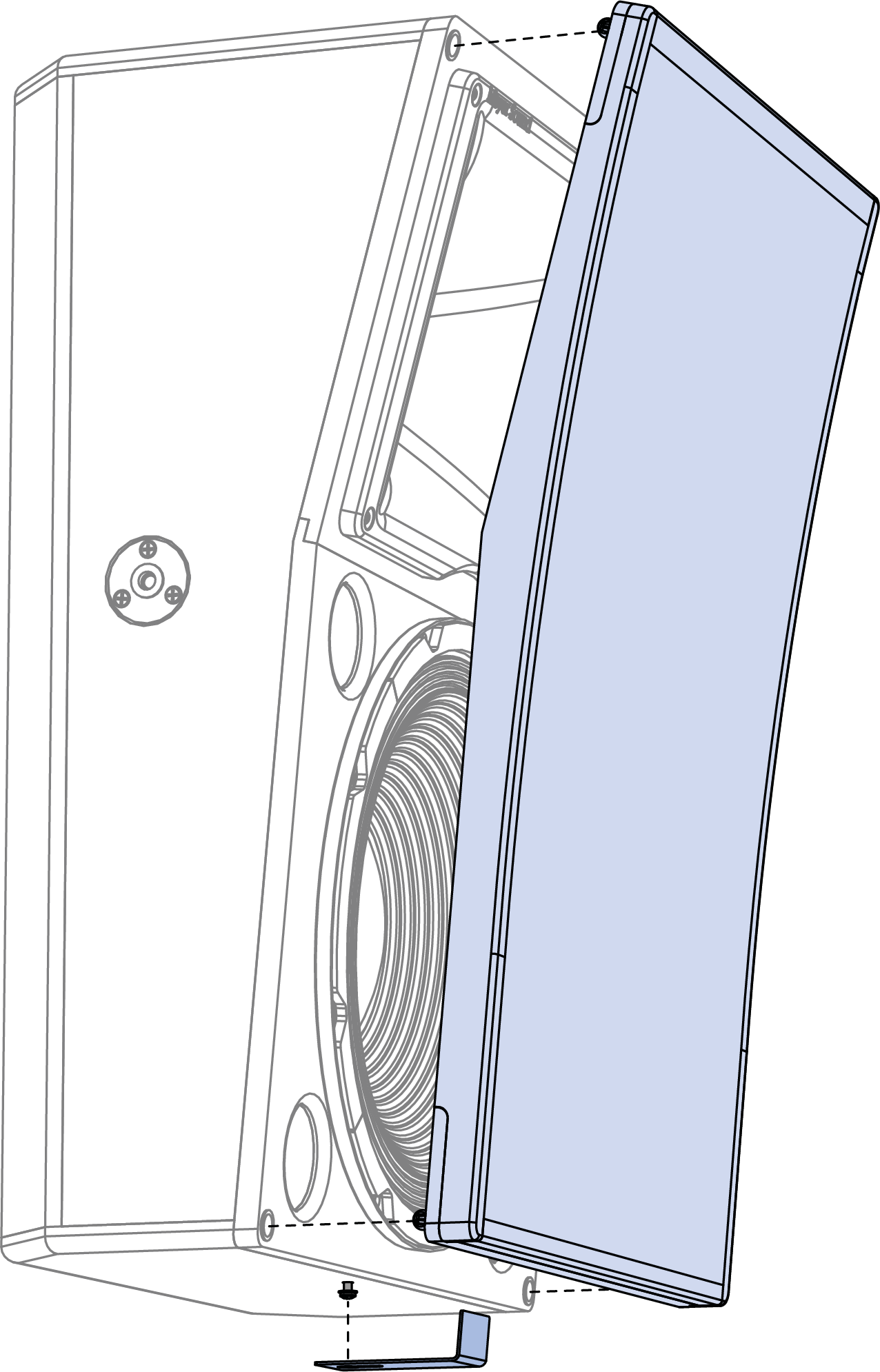
Re-tighten the pan head screw without the L-bracket installed.
Unsnap the corner treeloks of the grille frame and remove the grille.
Caution
For installations that require grille frames, do not remove the L-brackets securing HMS-12 and HMS-15 grille frames.
System Design and Integration Tools
MAPP System Design Tool
The MAPP System Design Tool is a powerful, cross-platform application for accurately predicting the coverage pattern, frequency response, phase response, impulse response, and SPL capability of individual or arrayed Meyer Sound loudspeakers.

MAPP System Design Tool
Whether planning for fixed installations or for tours with multiple venues, use MAPP to accurately predict the appropriate loudspeaker deployment for each job, complete with coverage data, system delay and equalization settings, rigging information, and detailed design illustrations. MAPP’s accurate, high-resolution predictions ensure that systems will perform as intended, thereby eliminating unexpected coverage problems and minimizing onsite adjustments.
The key to the accuracy of MAPP’s predictions is MeyerSound’s exhaustive database of loudspeaker measurements. Performance predictions for each loudspeaker are based on 3-dimensional, 65,000+ 1/48th-octave-band measurements taken in the MeyerSound anechoic chamber. The extraordinary consistency between Meyer Sound loudspeakers guarantees that predictions from MAPP will closely match their actual performance.
MAPP software allows for configuration of MeyerSound loudspeaker systems and definition of the environment in which they operate, including air temperature, pressure, humidity, and the location of prediction surfaces. Importing both CAD (.DXF) and Sketchup (.SKP) files containing detailed venue information to act as an anchor model to the prediction surfaces and a visual aid to facilitate prediction data interpretation is also possible.
Tip
See meyersound.com for support and more information about MAPP.
MAPP Capabilities
With MAPP, you can:
Simulate different loudspeaker configurations to refine system designs and determine the best coverage for intended audience areas
Model loudspeaker interactions to locate constructive and destructive interferences so that loudspeakers can be re-aimed and repositioned as necessary
Place microphones anywhere in the Model View space and predict loudspeaker frequency response, phase response, and sound pressure levels at each microphone position
Determine delay settings for fill loudspeakers using the Inverse Fast Fourier Transform and phase response feature
Preview the results of signal processing to determine optimum settings for the best system response
Automatically calculate load information for arrays to determine necessary minimum rigging capacity, front-to-back weight distribution, and center of gravity location
Generate and export system images and system PDF reports for client presentations
Synchronize GALAXY processor output channel settings in real-time with virtual or real GALAXY units, allowing in-the-field changes to be predicted during system alignments
Galileo GALAXY Network Platform
The Galileo GALAXY Network Platform is a sophisticated loudspeaker management tool for controlling all MeyerSound speaker types. The GALAXY loudspeaker processor extends a high level of audio control in driving and aligning loudspeaker systems with multiple zones. It provides a powerful tool set for corrective equalization (EQ) and creative fine-tuning for a full range of applications from touring to cinema.
Users can readily program the GALAXY processor using Compass software running on a host computer or via the Compass Go application for the iPad. Connecting MAPP to the GALAXY processor will also allow the user to push output channel settings created in MAPP as a starting point. Compass Control Software includes custom-designed settings for each family of speakers, as well as to integrate families together. For example, the Product Integration feature matches the phase characteristics between Meyer speaker families to ensure the most coherent summation.
Processing tools for inputs and outputs include delay, parametric EQ and U-Shaping EQ. Output processing also includes polarity reversal, Low-Mid Beam Control (LMBC), atmospheric correction, and All Pass filters.
The built-in summing and delay matrices allow a user to easily assign gain and delay values, respectively, at each cross point. This capability greatly facilitates using one loudspeaker to satisfy multiple purposes.
Front panel controls let a user intuitively and quickly operate a GALAXY processor without a computer during live use.
The GALAXY 408, GALAXY 816 and GALAXY 816-AES3 processor versions have the same audio processing capability with different I/O. See www.meyersound.com to locate their datasheets for more information.
HMS Accessories
Part Number | Accessory | Notes |
|---|---|---|
09.205.001.01 | MPS-488HPp external power supply (with US power cord) | Channel outputs equipped with Phoenix 5-pin male connectors |
09.205.001.02 | MPS-488HPp external power supply (with CE power cord) | |
484.065 | Phoenix 5-pin female cable mount connector | Connects to MPS-488HPp channel output connectors and HMS Input connectors |
524.014 | Bulk cable, no connectors (regular) | 500-ft spool, black |
524.015 | Bulk cable, no connectors (plenum) | 500-ft spool, white |
Note
Bulk cables use Belden 1502R (regular) or Belden 1502P (plenum) cable. Belden 1502 is a composite cable comprised of two 18 AWG wires for DC power, two 22 AWG wires for balanced audio, and one 24 AWG wire for audio shield. This single cable can deliver both DC power and balanced audio to loudspeakers at cable runs of up to 150 feet with only 1 dB of loss in peak SPL. Longer cable runs are possible with heavier gauge wires for DC power and separate cables for balanced audio. For more information, see Current Draw and Cable Requirements for HMS Loudspeakers.
Assemble IntelligentDC loudspeaker cables
When wiring IntelligentDC loudspeaker cables, each pin in the cable must align correctly with the corresponding pin in the MPS channel output connector (see Channel Outputs). Ensure the 48 V DC from the MPS power supply connects directly (and only) to the 48 V DC pins on the loudspeaker connector, and that the polarity aligns (negative to negative, positive to positive) to prevent damage to the loudspeaker. In addition, verify the audio pin polarity, as reversals in audio signals can affect system performance.
Wire | Gauge | Signal |
|---|---|---|
Red | 18 AWG | DC power, positive (+) |
Black | 18 AWG | DC power, negative (–) |
White | 22 AWG | balanced audio, positive (+) |
Blue | 22 AWG | balanced audio, negative (–) |
Shield | 24 AWG | balanced audio, shield |
Assembling Phoenix-to-Phoenix Loudspeaker Cables
When connecting loudspeakers equipped with Phoenix connectors to the MPS-488HPp power supply, you need a Phoenix 5-pin female to Phoenix 5-pin female cable. The following procedure documents how to assemble this cable.
 |
Assembled Phoenix-to-Phoenix Cable
If the cable has not yet been stripped, strip one end of the cable. Strip the outer shielding by 1 inch and then strip the black, red, blue, and white wires by 0.275 inch.

Insert the five exposed conductors into the five cable holes in a Phoenix 5-pin female cable mount connector. Use the following wiring scheme.

Pin Destinations for Phoenix 5-Pin Female Cable Mount Connector
Secure the conductors by tightening the five screws in the Phoenix cable mount connector. Screws should be torqued to 5–6 Nm(4.4–5.3 In-Lbs).

Caution
Screws should not be inserted into the Phoenix connector while the connector rests in a mating plug. Doing so will damage the contacts. During assembly, the Phoenix connector should only be held in place externally.
Repeat the previous steps and attach the other end of the cable to another Phoenix 5-pin female cable mount connector.
Verify the wiring polarity is correct for both cable ends
HMS-5 with FMB-HMS Fixed Mount Bracket Dimensions

HMS-5 With AMB-HMS Adjustable Mount Bracket Dimensions

HMS-10 with FMB-HMS Fixed Mount Bracket Dimensions
HMS-10 with AMB-HMS Adjustable Mount Bracket Dimensions
HMS-12 with FMB-HMS Fixed Mount Bracket Dimensions

HMS-12 with AMB-HMS Adjustable Mount Bracket Dimensions
HMS-15 with FMB-HMS Fixed Mount Bracket Dimensions
HMS-15 with AMB-HMS Adjustable Mount Bracket Dimensions
 |
MUB-HMS U-Bracket Dimensions

HY-HMS Half Yoke Dimensions
MYA-HMS-15 Yoke Dimensions
WH-MHS Wall Hinge Bracket Dimensions