Datasheet — MJF-208
Compact stage monitor
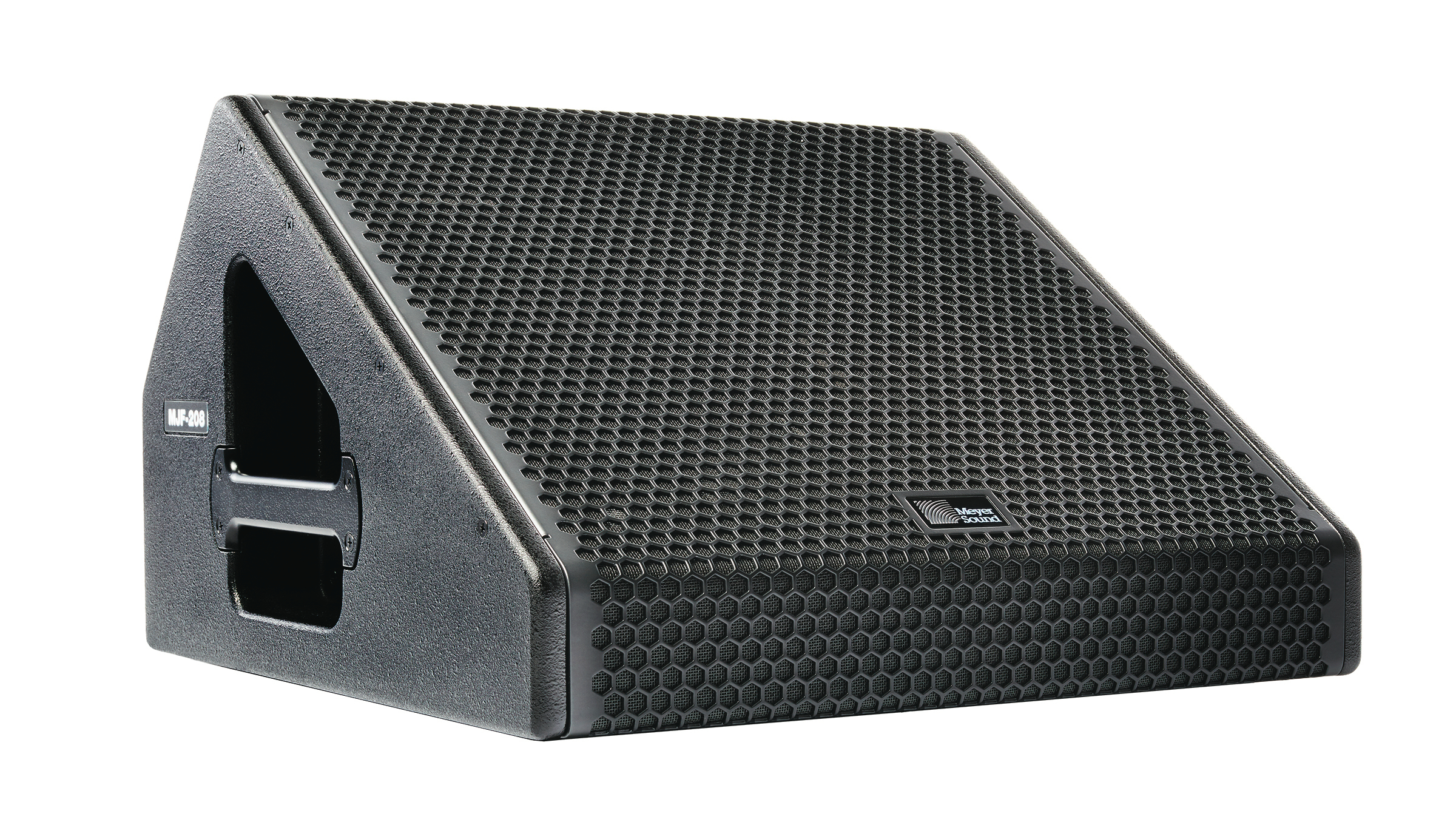
The MJF‑208 compact stage monitor brings the same high intelligibility and low‑frequency headroom of Meyer Sound’s acclaimed MJF line of stage monitors to a lighter, more portable cabinet. The MJF‑208 is ideal for monitoring applications with minimal stage space that do not require the higher output of the MJF‑212A or MJF‑210. All three stage monitors offer the self‑powered advantages of simplified setup, operation, and consistent stage‑to‑stage sound, while occupying a fraction of the truck space of similar monitors that require external amplification.


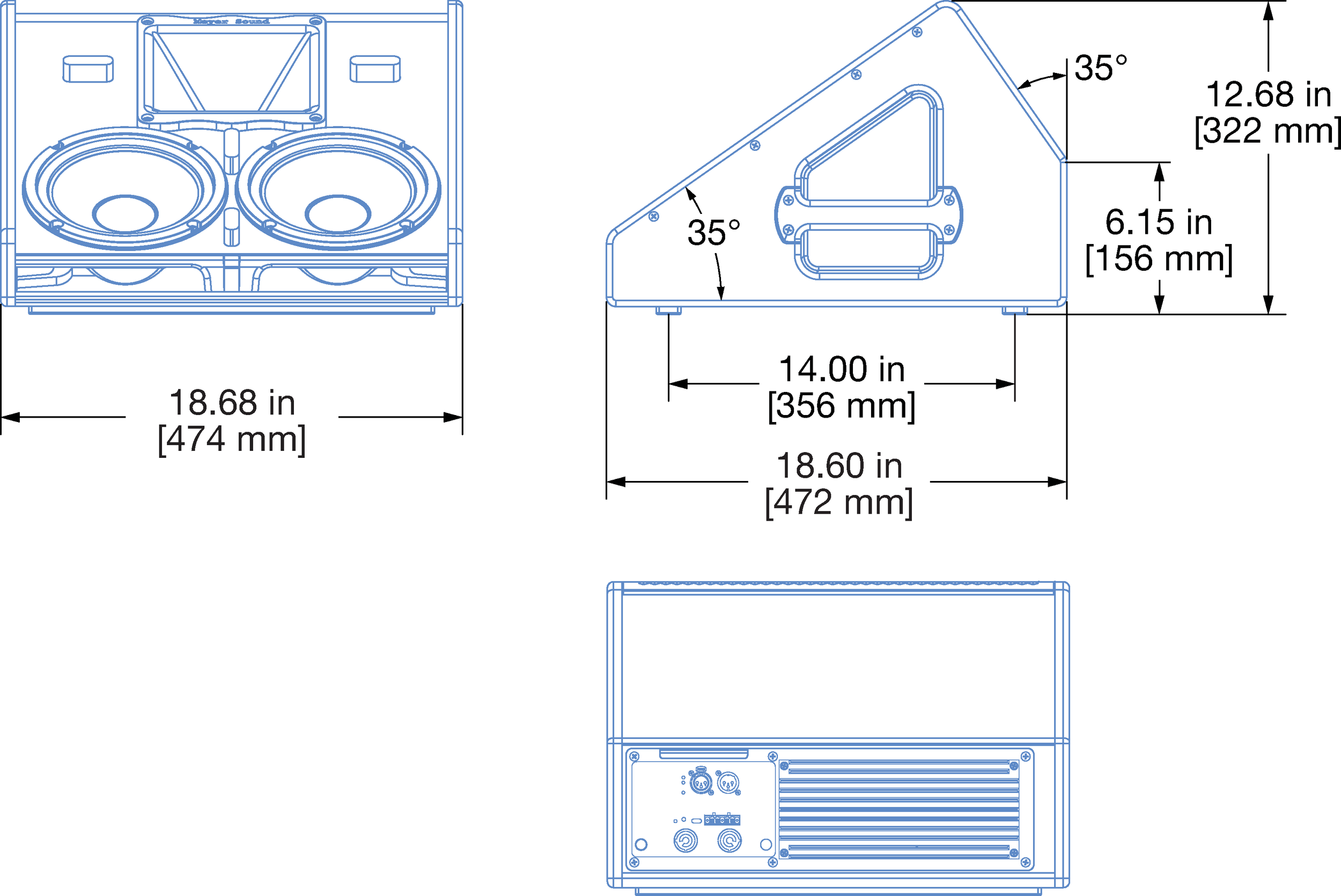
MJF-208 Loudspeaker and Dimensions
The MJF‑208’s 55 Hz to 18 kHz frequency range is phase corrected, ensuring that vocals and instruments are reproduced accurately with low distortion and no signal coloration. The flat phase and frequency response yield exceptional pattern control, minimizing interactions with nearby microphones and providing high gain before feedback.
The MJF‑208’s durable, vented enclosure houses two 8‑inch high‑power low‑frequency drivers, as well as a 3‑inch diaphragm compression driver coupled to a constant‑directivity horn. The dual‑driver design with optimized crossover and extremely accurate horn delivers extended headroom and symmetrical coverage not possible with other wedge monitor designs. The MJF‑208 need not be purchased in matched pairs when deploying left‑right configurations. The 70° horizontal by 50° vertical horn provides optimal coverage in smaller spaces that cannot accommodate a large number of monitors. The low‑profile cabinet slopes 35° from the stage to preserve audience sight lines.
Drivers are powered by a three‑channel, class D amplifier. The Intelligent AC™ power supply provides automatic voltage selection, EMI filtering, soft current turn‑on, and surge suppression.
The optional RMS™ remote monitoring system module enables comprehensive monitoring of loudspeaker parameters from a Mac® or Windows®‑based computer running Compass® control software. Optional XLR 5‑pin connectors for the MJF‑208 support use of composite cables to carry both balanced audio and RMS signals.
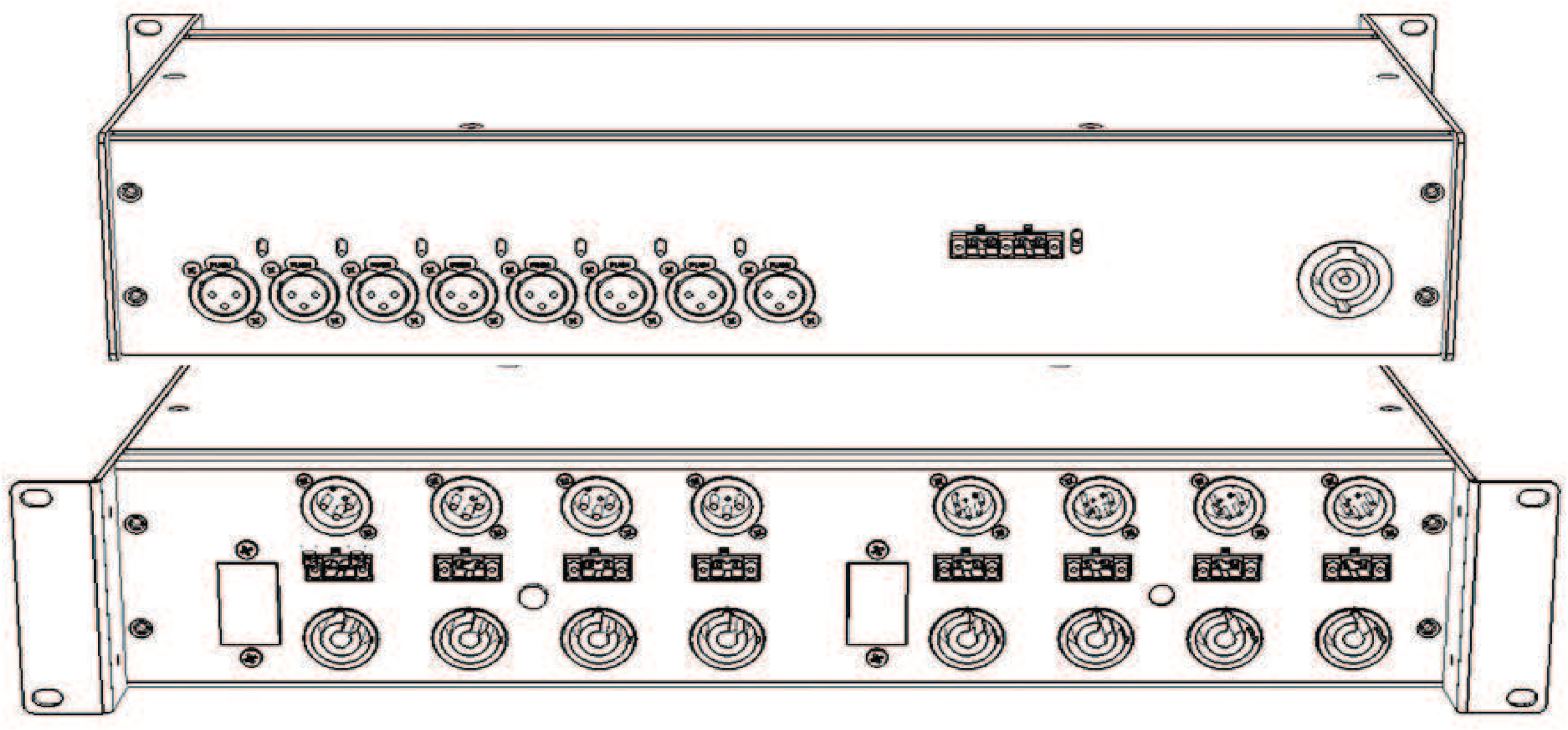
The optional MDM‑832 distribution module routes AC power, balanced audio, and RMS to multiple MJF stage monitors, further enhancing portability and ease of use. The MDM‑832 simplifies distribution with composite cables carrying AC power, balanced audio and RMS—streamlining setups and tear‑downs and reducing onstage cable clutter.
The MJF‑208’s cabinet is constructed of premium multi‑ply birch, coated with a durable, slightly textured black finish, and includes protective rubber strips on the bottom of the unit that prevent changes in position due to vibrations. A hex‑stamped steel grille lined with acoustical black mesh protects the drivers.
Features and Benefits
Small lightweight footprint with no external amplification occupies less stage and truck space
Self‑powered system simplifies setup and operation and ensures consistent stage‑to‑stage sound
Low‑profile cabinet preserves audience sight lines
High peak power ensures excellent transient response
Flat phase and frequency response and exceptional pattern control yield high gain before feedback
Applications
Small‑ or mid‑sized stages, clubs, houses of worship, or corporate AV
Main or backup vocal, or instrument monitor
Applications where space and portability are a factor
Accessories and Associated Products
Galileo GALAXY Network Platform — The Galileo GALAXY Network Platform provides state‑of‑the‑art audio control technology for loudspeaker systems with multiple zones. With immaculate sonic performance, it provides a powerful tool set for corrective room equalization and creative fine-tuning for a full range of applications.
 |
GALAXY Network Platform MDM-832 Distribution Module
MDM-832 Distribution Module — MDM‑832 units conveniently power systems, routing up to eight channels of AC power, balanced audio and RMS signals to loudspeakers.
 |
MDM-832 Distribution Module
Specifications
ACOUSTICAL1 | |
Operating Frequency Range2 | 55 Hz – 18 kHz |
Frequency Response3 | 60 Hz – 18 kHz ±4 dB |
Phase Response | 230 Hz – 16 kHz ±45° |
Linear Peak SPL4 | 129 dB with crest factor >16 dB (M-noise)7 128 dB (Pink noise), 129 dB (B‑noise) |
COVERAGE | |
Horizontal Coverage | 70° |
Vertical Coverage | 50° |
TRANSDUCERS | |
Low Frequency | Two 8‑inch high‑power cone drivers; 4 Ω nominal impedance |
High Frequency | One 3‑inch diaphragm compression driver; 16 Ω nominal impedance |
AUDIO INPUT | |
Type | Differential, electronically balanced |
Maximum Common Mode Range | ±5 V DC, clamped to earth for voltage transient protection |
Connectors | XLR 3‑pin female input with male loop output; optional XLR 5‑pin connector to accommodate both balanced audio and RMS signals. |
Input Impedance | 10 kΩ differential between pins 2 and 3 |
Wiring5 | Pin 1: Chassis/earth through 1 kΩ, 1000 pF, 15 V clamp network to provide virtual ground lift at audio frequencies Pin 2: Signal + Pin 3: Signal – Pin 4: RMS (polarity insensitive) Pin 5: RMS (polarity insensitive) Case: Earth ground and chassis |
Nominal Input Sensitivity | 0 dBV (1.0 V rms) continuous is typically the onset of limiting for noise and music |
Input Level | Audio source must be capable of producing of +20 dBV (10 V rms) into 600 Ω to produce the maximum peak SPL over the operating bandwidth of the loudspeaker. |
AMPLIFIER | |
Type | Three‑channel, Class‑D |
Total Output Power6 | 1770 W peak |
THD, IM, TIM | < 0.02% |
Cooling | Convection |
AC POWER | |
Connector | PowerCON 20 input with loop output |
Automatic Voltage Selection | 90–265 V AC |
Safety Agency Rated Voltage Range | 100–240 V AC, 50–60 Hz |
Turn‑on and Turn‑off Points | 90 V AC turn‑on, no turn‑off; internal fuse protection above 265 V AC |
CURRENT DRAW | |
Idle Current | 0.26 A rms (115 V AC); 0.25 A rms (230 V AC); 0.28 A rms (100 V AC) |
Maximum Long‑Term Continuous Current (>10 sec) | 1.4 A rms (115 V AC); 0.8 A rms (230 V AC); 1.7 A rms (100 V AC) |
Burst Current (<1 sec)7 | 2.2 A rms (115 V AC), 1.1 A rms (230 V AC), 2.6 A rms (100 V AC) |
Maximum Instantaneous Peak Current | 6.0 A peak (115 V AC), 2.9 A peak (230 V AC), 6.9 A peak (100 V AC) |
Inrush Current | < 20 A peak |
RMS NETWORK (OPTIONAL) | |
Two‑conductor twisted‑pair network that reports all operating parameters of amplifiers to system operator’s host computer. | |
PHYSICAL | |
Dimensions | W: 18.68 in (474 mm) x H: 12.68 in (322 mm) x D: 18.60 in (472 mm) |
Weight | 47 lb (21.3 kg) |
Enclosure | Premium multi‑ply birch with slightly textured black finish; 35° front angle |
Protective Grille | Powder‑coated, hex‑stamped steel with black mesh |
Notes
Loudspeaker system predictions for coverage and SPL are available in Meyer Sound’s MAPP System Design Tool.
Recommended maximum operating frequency range. Response depends on loading conditions and room acoustics.
Maximum SPL is the peak measured in free‑field at 4 m referred to 1 m using noise.
Linear Peak SPL is measured in free‑field at 4 m referred to 1 m. Loudspeaker SPL compression measured with M‑noise at the onset of limiting, 2‑hour duration, and 50 °C ambient temperature is <2 dB.
M-noise is a full bandwidth, (10 Hz–22.5 kHz) test signal developed by Meyer Sound to better measure the loudspeaker’s music performance. It has a constant instantaneous peak level in octave bands, a crest factor that increases with frequency, and a full bandwidth Peak to RMS ratio of 18 dB.
Pink noise is a full bandwidth test signal with Peak to RMS ratio of 12.5 dB.
B-noise is a Meyer Sound test signal used to ensure measurements reflect system behavior when reproducing the most common input spectrum, and to verify there is still headroom over pink noise.
Pins 4 and 5 (RMS) only included with XLR 5‑pin connector that accommodates both balanced audio and RMS signals.
Peak power based on the maximum unclipped peak voltage the amplifier will produce into the nominal load impedance.
AC power cabling must be of sufficient gauge so that under burst current rms conditions, cable transmission losses do not cause the loudspeaker’s voltage to drop below the specified operating range.
Architectural Specifications
The loudspeaker shall be a self‑powered stage monitor; its transducers shall include two 8‑inch cone drivers and one 3‑inch diaphragm compression driver on a 70° x 50° horn.
The loudspeaker shall incorporate internal processing electronics and a three‑channel amplifier, one channel for each driver. Processing functions shall include equalization, phase correction, signal division, and driver protection. Amplifier channels shall be class D.
Performance specifications, measured at 1/3‑octave resolution, for a typical production unit shall be as follows: operating frequency range, 55 Hz to 18 kHz; phase response, 230 Hz to 16 kHz ±45 degrees. Coverage shall be 70° horizontal by 50° vertical. Linear peak SPL shall be 129 dB with crest factor >16 dB measured with M‑noise, 1 m on axis with typical boundary loading.
Audio connectors shall be XLR 3‑pin or 5‑pin input with male loop output. XLR 5‑pin connectors shall accommodate both balanced audio and RMS signals.
The internal power supply shall perform automatic voltage selection, EMI filtering, soft current turn‑on, and surge suppression. Power requirements shall be nominal 100, 110, or 230 V AC line current at 50–60 Hz. UL and CE operating voltage range shall be 100–240 V AC at 50–60 Hz. Maximum instantaneous peak current draw shall be 6.0 A peak at 115 V AC, 2.9 A peak at 230 V AC, and 6.9 A peak at 100 V AC. AC power connectors shall be powerCON 20 with loop output. The loudspeaker shall optionally include the RMS remote monitoring system module.
Components shall be mounted in an acoustically‑vented, wedge‑shaped enclosure constructed of premium multi‑ply birch with a slightly textured black finish. The protective grille shall be hex stamped steel with black mesh screen. Dimensions shall be W: 18.68 in (474 mm) x H: 12.68 in (322 mm) x D: 18.60 in (472 mm). Weight shall be 47 lb (21.3 kg). The enclosure’s front angle shall be 35°.
The loudspeaker shall be the Meyer Sound MJF‑208.