User Guide — CueStation 5.5
User Guide — Cuestation 5.5
Control software
CueStation™ is the software interface to the D-Mitri audio system. It offers a graphic user interface that emulates a familiar mixing console and combines it with a cue-based automation system designed to integrate easily into theatrical, theme parks, and other show control situations.
This user guide serves primarily as a reference document. It contains some tutorial information but is not intended as comprehensive guidance for project development.
Meyer Sound offers classroom training courses to provide users with a thorough grounding in D-Mitri system design and in CueStation project development for D-Mitri systems.
D-Mitri and CueStation
This section briefly describes the components in a D-Mitri system, and how they fit together.
D-Mitri system components
The D-Mitri audio platform consists of a collection of D-Mitri modules, supporting hardware, and software to control and coordinate the hardware:
A D-Mitri system consists of at least one D-Mitri Core Processor (DCP) module, and several other modules of various types. Each module package should include a power cable and a copy of the D-Mitri Safety, Environmental, and Regulatory Information pamphlet.
A computer to run CueStation, under Mac OS X 10.6 or later or Windows 7
Network infrastructure for the D-Mitri modules to transport audio and control data.
D-Mitri Universal Firmware
CueStation software
CueStation Release Notes (PDF file)
CueStation User Guide (PDF file)
CueStation interface
CueStation models the controls of an analog mixing console in a graphical user interface, augmenting the console model through the use of data entry fields and tables. To make this kind of representation operate efficiently, CueStation apportions the functions of the console among a collection of functionally specific windows.
Most CueStation windows fall into one of two main categories: mixer programming controls, which look more or less like a conventional mixer, and automation windows that support the creation and organization of cues and cue lists.
The automation windows also allow control over how the control surface settings are captured into cues, the editing of cues, and putting cues into a cue list for a show.
Other windows, such as Access Policies or Key Mappings, provide an interface for configuring how you use CueStation. The next chapter provides a walk-through of some of the basic functions and features of CueStation.
CueStation audio signal flow
A complete internal signal path can be viewed in CueStation on a per-channel basis. In each CueStation window that represents a point in the audio signal path of a D-Mitri system, a set of Signal Path buttons is displayed.
Signal Path Buttons
Click an arrow button to open the CueStation window for the previous or next point in the signal path. Click the blue info button to open the Signal Path window. The Signal Path window shows the signal path for the currently selected channel. The current point in the path is highlighted, and shortcuts are displayed for all points. When passing signal for the selected channel, the various buttons illuminate in green.
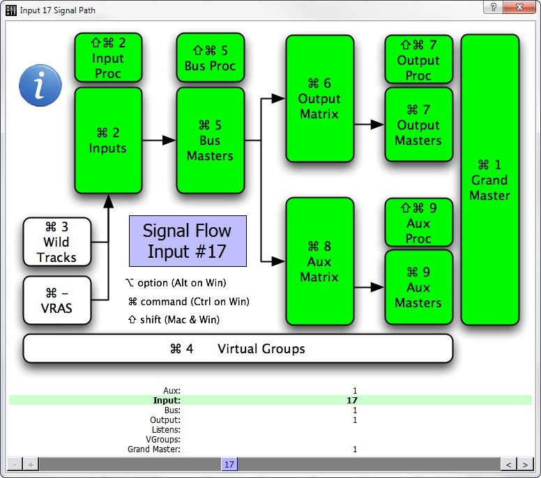 |
Signal Path Window
Drag the scrollbar at the bottom of the Signal Path window to change the displayed chan- nel. The displayed channel can also be changed by clicking the arrow buttons adjacent to the scrollbar, or right-clicking the purple Channel display.
To open the corresponding window for any point in the signal path, do one of the following:
Click any point in the displayed path.
Use the keyboard shortcut displayed for any point in the displayed path.
Mixer configuration
This section introduces the concept of D-Mitri mixer configuration. It describes what a mixer configuration is, and shows how to create a configuration that can quickly connect CueStation to an actual or virtual D-Mitri system.
CueStation has been designed to make the configuration as transparent as possible after the initial setup. When using CueStation with a configured system, you never have to worry about which channel is on which module, or about routing signal from one D-Mitri module to another. The entire system works as a unit.
Configuring a D-Mitri system
CueStation’s Mixer Configuration is a digital representation of all modules in a D-Mitri system. Every time the D-Mitri system is turned on or power cycled, it must receive a valid configuration before audio can be processed.
The number of D-Mitri modules in the system
The type and number of modules available
VLAN IDs and Switch Port settings
The number of buses, bus assigns, and VGroups For each I/O module:
The range of channels used by the module, and in some cases, the type of channels
The host DCP module
A valid configuration never duplicates channel numbers per channel type (e.g., two inputs cannot be simultaneously mapped to channel 10). A configuration can be loaded automatically at power on if a project is saved to flash memory. A configuration can also be sent from a CueStation client as part of a project file.
If one D-Mitri module within a larger system goes offline, the configuration is automatically re-sent to Processor modules once the system has reconnected.
The following section describes how to configure the system using the Mixer Configuration window.
Connecting to the D-Mitri system
You can try your hand at conducting a bit of simple mixer configuration by connecting to a D-Mitri system or to VirtualD-Mitri. Follow these steps to make the connection:
Connect your CueStation client computer to the D-Mitri control network.
In CueStation, choose Network > Connect to open the Connection Manager window.
Select a D-Mitri system (or VirtualD-Mitri) from the list, and click Connect (all windows).
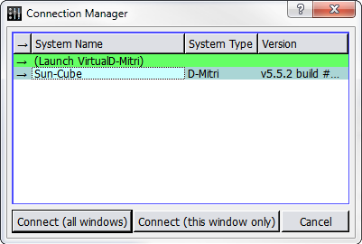
Connection Manager Window
Tip
To quickly connect individual CueStation windows to a D-Mitri system, system names can be dragged from the Connection Manager window onto any other CueStation window.
CueStation connects to the selected D-Mitri system, or to VirtualD-Mitri, which emulates a D-Mitri system. CueStation window title bars reflect the name of the connected system.
Configurations in D-Mitri flash memory
Meyer Sound provides a configuration file for your system that is stored in the flash memory of system Processor modules.
Open CueStation.
Choose Network > Connect. Select your system from the list, then click Connect (all windows).
Choose Windows > Mixer Configuration to open the Mixer Configuration window. If you are running CueStation for the first time, the Mixer Configuration window opens by default.
Choose Projects > Open Project from Flash.
Enable the Load Project and Send Configuration options, then click Open. CueStation loads the configuration stored in the Processor module flash memory and sends the configuration to the D-Mitri system.
Verify that the GNet Switch port settings in the System Configuration pane match the system diagram provided by Meyer Sound.
Choose Projects > Save Project As to save a copy of your configuration to the computer running CueStation.
If you are working offline with VirtualD-Mitri, hardware must be added manually.
Manually configuring modules
Open CueStation, then connect to the system you are configuring.
Choose Windows > Mixer Configuration to open the Mixer Configuration window. If you are running CueStation for the first time, the Mixer Configuration window is the window that first appears when CueStation opens.
Instruct CueStation to detect what hardware is installed.
Configuration > Query Hardware for Configuration populates the System Configuration pane with all modules detected in the D-Mitri system. Query Hardware for Configuration does not detect I/O modules that are not part of the active configuration.
The Auto-Setup button configures all detected I/O points to default.
If CueStation is connected to VirtualD-Mitri, modules must be added to the project by choosing Modules > New Module.
Tip
Modules can also be added to the configuration by dragging entries from the Module Types pane into the System Configuration pane.
An alert is displayed if the selected configuration does not match the active configuration. Click Details for more information about the differences between configurations.
Sending a Configuration to a D-Mitri System
Click Send Config in the upper right corner of the Mixer Configuration window to send a completed configuration to the D-Mitri system. A D-Mitri configuration does not take effect until you send it to the modules in your system.
CueStation posts a notification in its Log window that the configuration has been sent. If the system is running a configuration that has previously generated warnings, the System Status icon displays a warning to indicate a problematic configuration. The CueStation mixer window shows faders and other controls corresponding to the configuration.
Project title
Projects are assigned titles that display in the CueStation windows. Project titles are independent of dmitriProject file names.
Choose Projects > Set Project Title.
Enter a new title.
Press Enter or click OK.
Mixer Configuration window
The Mixer Configuration window features three tabs: Modules, Aliases, and Event Triggers.

Mixer Configuration Window, Modules Tab
Though most of the information the Mixer Configuration window provides is specific to each of the tabs, the window does offer several persistent controls in the border areas outside the tab fields, as described in the following table.
Control | Description |
|---|---|
Send Config button | Sends the current Mixer Window configuration to CueStation. |
Config button menu | A pull-down menu containing the following functions: New Config, Rename Config, Duplicate Config, Delete Config, Set Config ID, Lock Config, Unlock Config. |
Show | Filters view by I/O point type (All, Input, PAFL, etc.). |
# Cue List Players | Enter the total number of cue list players here. |
# buses | Enter the total number of buses here. |
# Assigns | Enter the total number of bus assigns here. |
# VGroups | Enter the amount of virtual groups here. |
System IP | You can enter an IP address for the system in this text field. Pressing the System IP button itself opens the System IP Config dialog, with fields for IP Address, Netmask, and Gateway. |
Enable GNet Failover | Enables use of the secondary Ethernet audio network connection of D-Mitri modules (AVB 2). |
Modules tab
The Modules tab of the Mixer Configuration window displays three separate panels; Module Types, System Configuration information, and I/O Points.
The Module Types list contains a list of D-Mitri module types. To add a specific module type to your configuration, you can drag a module type name from the list into the adjacent System Configuration table.
The System Configuration table in the Modules tab displays the modules in your configuration and displays each module’s networking configuration. The System Configuration table contains the following default columns.
Field | Description |
|---|---|
Processing Gauge | Displays a visual graph of the allocated resources for each DCP: |
Green indicates the allocated inputs. Orange indicates the allocated buses. Purple indicates the allocated outputs. | |
Module Type | The Module Type is shown when an entry is created. Must match the physical module for the configuration to work properly. |
Name | Displays the module name. Module Name must match the name programmed into the module. |
Unit | Automatically assigned unit name to distinguish between multiple processing units. Value can be changed. |
TX VLAN | Provides a field for you to enter the selected module’s GNet transmission VLAN. |
RX VLANs | Provides a field for you to set the selected module’s GNet reception VLANs. |
GNet Switch Port | Provides a field for you to set the selected module’s GNet Switch Port. |
Comment | Provides an area for you to enter text comments about a module. |
Status | Displays module status. Values are Emulated, Online, or Offline. |
The I/O Points table in the Modules tab displays the input and output information for each module in the chosen D-Mitri system. I/O Points that lack corresponding modules in the Modules table are highlighted in red.
The I/O Points table contains the following default columns.
Field | Description |
|---|---|
I/O Type | The type of the I/O point is automatically assigned during configuration. |
Index | The index number of the I/O point is automatically assigned during configuration. |
I/O Location | The location of the I/O point is automatically assigned during configuration. |
Processor | Shows a number from 1–4 to indicate which DCP processes the I/O point. |
Default Label | Provides a field for you to set the selected module’s GNet reception VLANs. |
Comment | Provides an area for you to enter text comments about a module. |
Default Label | The default label of the I/O point is automatically assigned during configuration. |
CueStation’s Mixer Config window provides a Fill Down function for Modules and I/O Points column values.
Select a range of entries in the Modules tab or I/O Points tab.
Right-click in a column and choose Fill Down Selected.
In the Specify Initial Default Label dialog, enter a value or comment.
Press Enter or click OK.
Each selected item changes to sequentially follow the initial entry.
The contextual menu for the Default Label column also provides an option to reset a selection of label values to their defaults.
Note
When manually editing fields, invalid entries are highlighted in pink. Attempting to send invalid configurations results in a Mixer Configuration warning.
The Modules List displays D-Mitri modules of all connected systems, using a [System- Name.ModuleName] syntax.
Finally, the Modules tab also shows an Auto Setup button, which configures the Mixer Configuration window to the current hardware or virtual setup.
Aliases tab
The Mixer Configuration window’s Aliases tab displays a list of network address alias definitions for modules in the D-Mitri system. These aliases enable you to refer to D-Mitri modules and command strings in CueStation by custom names.
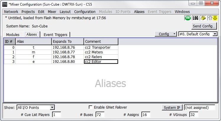
Mixer Configuration Window, Aliases Tab
The Aliases tab in the Mixer Configuration window displays a table containing the following default columns.
Field | Description |
|---|---|
ID # | The Alias ID number: assigned automatically when the alias is created, but can be changed. |
Alias | Alias name: assigned automatically when the alias is created, but can be changed. |
Expands To | Enter the IP address or command string that is associated with the alias. To expand an alias to multiple values, separate the values with a comma. |
Comment | Provides an area to enter text comments. |
Event Triggers tab
The Mixer Configuration window’s Event Triggers tab provides a place for you to define and view Event Triggers. Event Triggers specify how the D-Mitri system should respond to incoming event strings, such as MIDI messages. Event Triggers defined in the Event Triggers tab become active when you send the system configuration to the D-Mitri system using the Mixer Configuration window’s Send Config button.
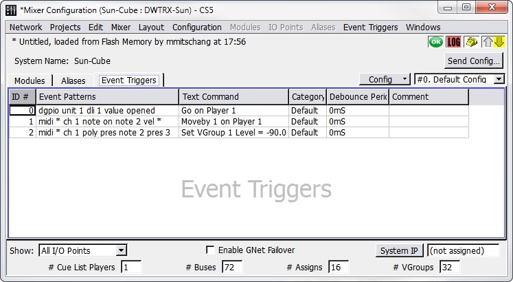
Mixer Configuration Window, Event Triggers Tab
Choose Event Triggers > New Event Trigger to add Event Triggers to the list. The Event Triggers menu also contains commands to duplicate and delete Event Triggers.
The Mixer Configuration window’s Event Triggers tab displays a table containing the following default columns.
Field | Description |
|---|---|
ID# | The Event Trigger number: assigned automatically when the Event Trigger is created, but can be changed. |
Event Patterns | An Event Trigger consists essentially of two parts: the trigger condition and the action to execute when the condition occurs. The trigger condition can be one of several event patterns. Right-click in the event pattern column and select an event pattern template to add an event pattern to a trigger definition. Template text can be edited directly in the table to define the event pattern portion of the Event Trigger. . The event pattern templates are:
|
Event Patterns (cont.) | All Notes Off |
Note Off | |
Note On | |
Polyphonic Key Pressure | |
Control Change | |
Program Change | |
Channel Pressure | |
Pitch Bend | |
Text Command | The second half of an Event Trigger is what action the D-Mitri system executes when the trigger condition occurs. The command to execute can be one of several CueStation text commands. To assign multiple commands to an Event Trigger, separate them with a semicolon (for example: log recalling cue; recall cue 5). Right-click the Text Command field and choose a text command template to add a text command to a trigger definition. You can then edit the template text directly in the table to define the text command portion of the Event Trigger. . The text command templates are:
|
Category | Provides a means by which to categorize Event Triggers. Use this field to enter a text value representing the category to which you want to assign an Event Trigger. Click the Category column heading to sort the list of Event Triggers by category, or right-click the Category column heading to filter the display by Category content. |
Debounce Period | Specifies a debounce period for the selected Event Trigger, in milliseconds. The debounce period defines a time during which the trigger only fires once. For example, entering 500ms in the field would ensure that the trigger doesn’t fire more than twice a second. |
Comment | Provides an area for text comments. |
Configuring a D-Mitri backup module
It is beneficial to designate a live backup module, which you can set to come online should a primary module suddenly become disabled or disconnected. Settings on backup modules are kept in sync with primary modules, ensuring that the backup modules come online seamlessly to assume the tasks of the modules they replace. In D-Mitri systems with multiple DCPs, a single backup DCP can take over for any one of the primary DCPs.
You can use CueStation to designate DCP, DCM-2, DCM-4, and Wild Tracks modules as backup modules. The following table briefly describes how each kind of backup module should be set up.
Module | Backup Configuration |
|---|---|
DCP | A live backup DCP must be given the unit ID DCP-X in the Mixer Configuration window, and must be plugged into the last matrix link port, labeled Backup, on a DCM module. One live backup DCP can stand in for any one of up to 4 primary DCP modules. |
DCM-2 or DCM-4 | A live backup DCM-2 or DCM-4 must be given the unit ID MTRX-X in the Mixer Configuration window. |
Wild Tracks | Both the primary and the live backup Wild Tracks units must be configured with the same unit ID (though this ID can be whatever you want). Associate I/O Points only with the primary Wild Tracks module. |
Disabling D-Mitri modules remotely
D-Mitri modules can be enabled or disabled directly through the System Status window, or by executing a Set Disabled Modules command with a subcue. Disabling marks the module as one that should not be used for passing audio, forcing the system to use its assigned backup modules for audio routing instead.
Status window module enable or disable
Right-click a module’s Status field to raise a context menu with choices to set the module to Enabled or Disabled.
Subcue window Set Disabled Modules command
The External Command subcue Live Backup can be used to enable or disable the module.
Testing a Configuration
Once a configuration has been sent to the CueStation system, it can be tested by generating test signals with CueStation and with signals created by connected external sources.
Testing with internally generated signals
Channel test functionality is built into the multiple windows in CueStation. This functionality allows testing of a configuration and connected loudspeakers. Test signals can be generated at the inputs, outputs, and several other locations in the CueStation signal path.

Channel Test Controls
Channel Test Controls offer the following controls.
Control | Function |
|---|---|
Channel Test Set | Sets the range of channels to be tested. Enter a single channel, a range of channels, or choose Reset to All Channels. Individual channels are separated by commas, channel ranges are indicated with hyphens. For example, typing 1,14,36–41 in the field specifies a test for channels 1, 14, and 36 through 41. |
Merge/Replace | Toggle whether to merge the chosen test audio with other output in the selected channels, or to replace the output with the test audio. |
Channel Test Type | Determines the type of test audio. Options include Voice, Voice and Pink Noise, Pink Noise (8 seconds), Log Sweep, and Pink Pulse. |
Channel Test Level | Determines the level of generated test signals. This setting operates independently of all level and trim controls in the CueStation signal path. |
Start/Stop Test | Begins the test. While the test is running, the Stop Test button ends the test. |
Current Channel | Indicates the channel that is currently being tested. Values that are manually entered in this field act as offsets. |
Transport buttons | Used for manual changes to the channel sequence. Test signal can be skipped to the previous or next channel, looped on the current channel, and paused. |
Preparing for a channel test
Choose Windows > Inputs to open the Inputs window.
Choose Display > Show Channel Test Controls to reveal the signal generator controls at the top of the Inputs window.
Click the Master Input Select button to select all Input channels.
Command-click (Mac) or Ctrl-click (Windows) the Unity button on any Input channel to set all selected channel faders to Unity.
In the bus assigns section of Input 1, select Bus 1. Repeat for all inputs, cascading the Bus selection (Input 2 to Bus 2, and so on).
Choose Windows > Matrix to open the Matrix window.
Choose Matrix > Set Diagonal, Buses, Outputs. A diagonal matrix mix is created with levels set to unity gain.
Choose Windows > Output Masters to open the Output Masters window.
Click the Master Output Select button to select all input channels.
Command-click (Mac) or Ctrl-click (Windows) the –inf button on any Input channel to set all selected channel faders to –inf.
Choose Windows > Grand Master to open the Grand Master window.
Click the Unity buttons for System Level and Trim to set fader levels to Unity.
Running a channel test
Complete the steps detailed in Preparing for a Channel Test.
Enter a value in the Channel Test Set field to set the range of channels to test.
Choose an option from the Channel Test Type menu to set the type of test signal.
Enter a Channel Test Level value to set the test signal level in dB.
Click Start Test to begin the channel test.
Choose Windows > Output Masters to open the Output Masters window.
Slowly increase the output fader levels until the test signal is playing back through connected loudspeakers at the necessary level. To adjust the levels of all Output channels simultaneously, click the Master Output Select button and then hold command (Mac) or Ctrl (Windows) while adjusting any Output channel fader.
Tip
For manual control over the test sequence, use the Cycle button in conjunction with the Skip to Previous Channel and Skip to Next Channel buttons.
Testing with external signals
External test signals can be fed into the CueStation system’s inputs, andthen sent to any or all outputs. The following procedure uses a single input point, Input 1, as an example.
Choose Windows > Inputs to open the Inputs window.
Click the Unity button for Input 1 to set the fader level to Unity.
In the Bus Assigns section of Input 1, select Bus 1.
Choose Windows > Matrix to open the Matrix window.
Choose Matrix > Set Diagonal, Buses, Outputs. A diagonal matrix mix is created. All bus masters and output masters are set to Unity.
Choose Windows > Grand Master to open the Grand Master window.
Click the Unity buttons for System Level and Trim to set fader levels to Unity.
Audio connected to Input 1 is mixed to Output 1. To change the output path, select a different bus from the bus assigns section of Input 1.
Working offline with VirtualD-Mitri
CueStation provides a client interface to D-Mitri server modules. VirtualD-Mitri is a software-based server component for CueStation. If no actual D-Mitri module is available, or when experimenting with CueStation without having to connect to an actual D-Mitri module, use VirtualD-Mitri.
CueStation and other clients normally connect to the server running on D-Mitri. When it is necessary to do cue programming work without having access to hardware, VirtualD-Mitri provides a simulation of the system.
VirtualD-Mitri window
The VirtualD-Mitri window, when expanded, provides status information and a set of tabs that allow control of specific server components.
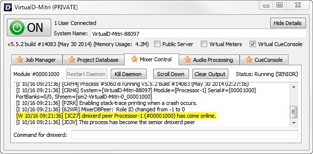
VirtualD-Mitri Window
Open CueStation.
Choose Network > Connect.
Select Launch VirtualD-Mitri.
Click Connect (all windows).
VirtualD-Mitri launches and CueStation connects to VirtualD-Mitri. CueStation behaves as though all hardware is connected. Due to the nature of the system simulation, the Query Hardware for Configuration command is not available. In addition, CueStation functions that involve D-Mitri flash memory are simulated using the client computer’s hard drive.
Main controls
The VirtualD-Mitri window contains the following controls for configuration.
Control | Function |
|---|---|
Show/Hide Details | Expands the VirtualD-Mitri window to display status information, five window tabs, and various controls. Click Hide Details to reduce the window down to a minimum size. See “Control Tabs” on page 18 for more information. |
System Name | By default, the VirtualD-Mitri is given a system name appended with a number. This system name can be edited when VirtualD-Mitri has been turned OFF. |
Public Server | Enabling the Public Server option allows other CueStation clients on the network to discover the instance of VirtualD-Mitri. Disabling this option prevents other CueStation clients on the network from discovering the instance of VirtualD-Mitri. Regardless of the Public Server setting, CueStation software is able to discover a VirtualD-Mitri server that is running on the same computer. |
Virtual Meters | Enabling the Virtual Meters option will simulate meter activity on all channels for testing purposes. |
Virtual CueConsole | This option enables VirtualD-Mitri to emulate a set of CueConsole2 commands with on-screen GUI representations of CueConsole2 control surface modules. See Virtual CueConsole, for more information. |
Status Information
System name, version number, memory usage, and build date are displayed near the top of the VirtualD-Mitri window.
Control tabs
The five VirtualD-Mitri window tabs have different sets of control buttons. Two of these control the server component background processes, program routines that are responsible for monitoring communications and status, and providing server services.
Restart Daemonis enabled only when the background process associated with the selected tab has been killed. Killing and restarting a background process is equivalent to rebooting that component of the server.Kill Daemonshuts down the background process associated with the selected tab.Scroll Downmoves the tab’s scrollbar to the bottom of the message list.Clear Outputremoves all the messages from the selected tab.
Job Manager tab
The Job Manager tab contains the output of the djobd daemon, which launches all of the other daemons and dictates their roles in the system. It's also responsible for restarting the other daemons if they exit.
Project Database tab
The Project Database tab lists system messages regarding the database background process, its communication with other background processes, and any project stored within the database. The database process controls access to subcues, cues, cue lists, and other project components.
Mixer Control tab
The Mixer Control tab lists system messages regarding the mixer background process, its communication with other background processes, and the status of various signal mix paths. The mixer background process is responsible for controlling and adjusting the signal mix.
Audio Processing tab
The Audio Processing tab contains the dcasld daemon. This daemon maintains the state of all system control points, as well as related tasks such as cue recalls and cue lists.
CueConsole tab
The CueConsole tab has controls for the CueConsole background process and lists system messages pertaining to the process, its communication with other background processes, and the status of any connected CueConsole modules. The CueConsole background process is responsible for monitoring and controlling the movement of CueConsole controls. This process is started automatically when VirtualD-Mitri starts. For more information, see Virtual CueConsole.
Virtual CueConsole
Virtual CueConsole windows emulate a set of CueConsole2 commands with GUI representations of CueConsole2 control surface modules. These windows serve as on-screen representations of the physical units, allowing users to program and test CueConsole2 behavior and mapping when no CueConsole2 hardware is available for use.

Virtual CueConsole Window (Transporter module shown)
Open CueStation and connect to VirtualD-Mitri.
Choose Windows > Commands.
Click Add Entry.
Right-click the Type field of the new entry and select CueConsole2.
Right-click the Command field of the new entry and select one or more of the following:
Map Editor Module
Map Fader Module
Map Meter Module
Map Transporter Module
Click Recall Selected. A new window appears for each selected module. All CueConsole2 modules are supported.
CueStation mixer controls
Using CueStation’s mixer windows requires familiarity with a set of common interface control elements. This section describes these control elements in the context of their use in the various CueStation mixer windows.
Inputs window
CueStation input channel strips can include a broad array of controls. These controls vary with the active CueStation configuration.
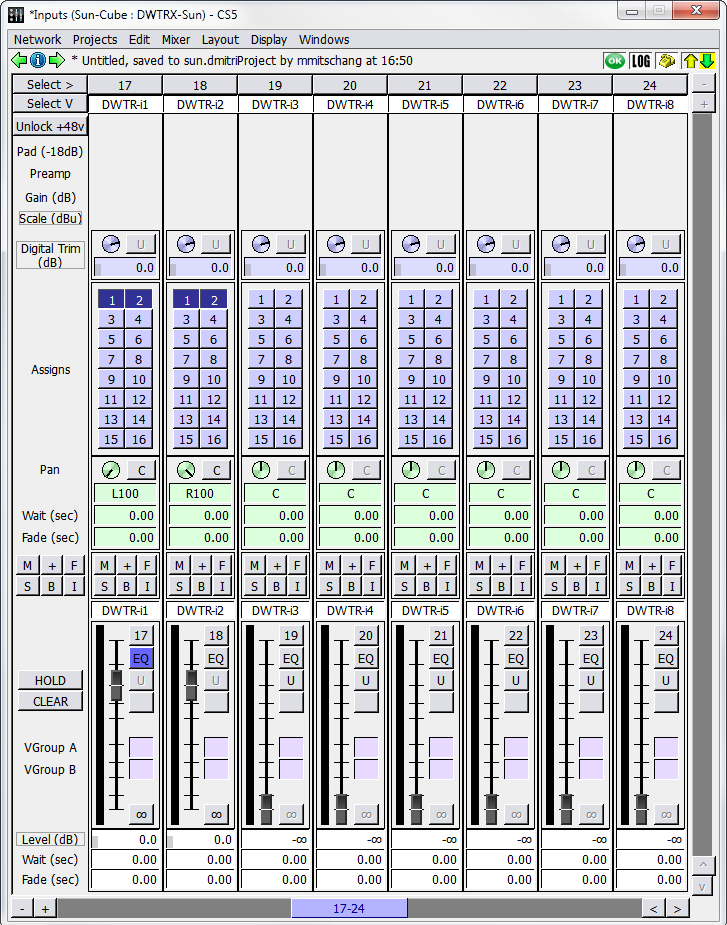
Inputs Window
Input channel strips include the following controls.
Control | Function |
|---|---|
Channel Select button | The Channel Selects button is labeled with its channel number (assigned when system was initially configured). It has a function for both automation and mixing. When capturing cues, the selection of channels can be used to constrain the range of channels captured into subcues. More information on using Channel Selects can be found in CueStation Automation. |
Fader Label text box | Faders can be automatically labeled when configuring the mixer, or manually labeled by typing a new label in the box. |
Auxiliary Send level or pan box | This control appears only when the mixer is configured for auxiliary sends and Display > Show Aux Sends is selected. |
Pre-Fader Listen Button | The pre-Fader Listen button is displayed if Control Points for PFL have been mapped. |
+48v Phantom power enable button | The phantom power setting can only be changed after clicking the Unlock +48v button on the far left. |
Pad (-18db) button | Reduces signal levels by 18 dB. |
Preamp button | Toggles the built-in preamplifier on or off. |
Gain knob | This knob controls Analog gain. |
Scale display | This display shows the signal scaling factor from the combination of Pad, Preamp, and Gain values. This control is active only for analog input or output channels. |
Trim knob | Drag Trim knobs or their associated value boxes to adjust the value. Values can also be typed directly in the associated text box. The adjacent Unity button resets the control. These trims can be used to adjust the relative levels of the automated mix during a performance without interfering with the overall contour of the automation. |
Bus Assign channel buttons | These buttons are arranged in paired (left/right) columns. To select a bus with a higher number than what is listed, right-click the buttons and select an available bus from the context menu. |
Pan control knob | Drag the knob to adjust the value, type a value into the associated text box, or click the text and drag up and down. The adjacent Center button resets the control. |
Wait and Fade timing boxes | The Fade time specifies how long it should take for the pan control to reach the desired position. The Wait time specifies how much time passes before the fade begins. A set of automation controls, supporting Mute, + (polarity), Flip (restores Level control when swapped with Aux, Trim, etc.), Solo, EQ Bypass, and Isolate. A master set of controls to the far left of the fader strips provides global control, toggling or resetting all buttons simultaneously. |
Fader level control | Fader for controlling channel level. See Fader Level Control, for more information. |
Scroll Bar | Drag to change the currently displayed channels. Addition and Subtraction buttons adjust the number of simultaneously displayed channels. Arrow buttons bank the displayed channels left and right. Right-click the scroll bar to choose the first displayed channel from the channel selection grid. |
CueStation provides a set of keyboard modifiers to use when changing settings across a selection of several inputs or outputs. Using these modifiers, channels can be controlled in stereo pairs or as larger selections.
To apply changes to a stereo pair on an absolute basis, select one channel of the pair, and hold the Shift key while making changes.
To apply changes on an absolute basis to all selected channels, hold Command (Mac) or Ctrl (Windows) while making changes.
To apply changes to a stereo pair in a relative fashion, such that the channels adjust uniformly while maintaining their differences, hold Shift+Option (Mac) or Shift+Alt (Windows) while making changes.
To apply changes to selected channels in a relative fashion, such that channels with different settings adjust uniformly while maintaining their differences, hold Command+Option (Mac) or Ctrl+Alt (Windows) while making changes.
Fader level control
The fader controls are similar across all mixer windows.
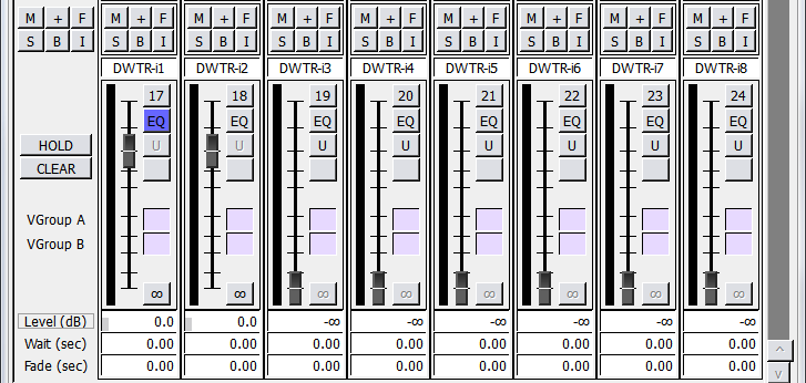
Fader Section (Mixer Windows)
The fader control section contains the following elements.
Element | Function |
|---|---|
Mute button | Mutes the signal present on the channel. |
Invert button | Inverts the polarity of the signal present on the channel. |
Flip button | Enables the fader to switch between controlling Channel level, Aux level, and Trim level. The destination and value of the fader control is indicated in the Level field directly below the fader. |
Solo | Solos the signal present on the channel. Right-click the Solo button and choose Enable Solo-Safe to prevent a channel from muting when another channel has Solo-in-place engaged. |
EQ Bypass | Bypasses all EQ settings of the channel. |
Isolate | Isolates the channel from automation. |
Signal Meter | The signal meter shows the level of the signal. It appears to the immediate left of the fader slider. |
Fader Slider | Drag this slider up and down to adjust the level. |
Channel Number | The channel number appears at the top-right of the control, corresponding to the channel number at the top of the channel strip. Click the channel number to disable the channel completely. |
EQ shortcut button | Opens the EQ window. It is enabled only when the system is configured to allow signal processing. |
Unity (0 dB) shortcut button | Provides a shortcut to set the channel level to unity. |
Listen button | A Listen button is enabled only when a Listen output is configured. The listen button can be mapped to a Listen output or to a set of Listen outputs using a set of checkboxes that become available when Listen output is configured. When a listen channel is enabled in the Master Output section, listen channel number is indicated on the button of each channel. An asterisk indicates multiple overlapping assignments. |
VGroup boxes | Enter a number or drag the box to assign a channel to a VGroup. When the channel is assigned to a VGroup, its fader shows a green scaling bar along the fader track, indicating the scaling factor being applied to the fader level. If the scaled level is above 0 dB, it is shown with a yellow bar (orange when using the Dark color scheme). When using two VGroups, the scaling factor is the product of the VGroup levels (multiplicative, not additive). |
Off (-inf dB) shortcut button | Provides a shortcut to set the channel level to -infinity. |
Level Wait, Fade value boxes | Meters and value can be dragged, and values can be typed directly. |
Global controls
Along the far left of the control panel, adjacent to and outside the channel strips, are some controls and labels. These controls are listed in the following table from top to bottom, with variations dependent on the mixer configuration.
Control | Function |
|---|---|
Master Channel Select button | This indicates whether any channel has been selected and toggles the Channel Select for all faders simultaneously. |
Auxiliary Select button | The Auxiliary Select button is labeled with the Auxiliary Number, and a text box for the Auxiliary Label. These controls appear only when the mixer is configured for aux- iliary sends and Display Show Aux Sends is selected. Double-click the label to flip the Aux Fader and Channel Fader controls. |
Unlock +48v button | Makes the +48v Phantom power enable button accessible on each channel. |
Digital Trim button | When double-clicked, Digital Trim flips the Trim and Level controls. The label text changes to indicate which type of control the adjacent pan pot adjusts. To switch back, click the F button. |
Master set of automation controls | These controls include Mute, + (polarity), Flip (restores Level control when swapped with Aux, Trim, etc.), Solo, EQ Enable, and Isolate. These buttons allow the settings to be toggled globally for all inputs. |
Two global Auxiliary Select buttons | Each button is labeled with its Auxiliary Number. |
HOLD button | When enabled, multiple PFL buttons can be activated simultaneously. When disabled, only one PFL can be activated at a time. |
Checkboxes | These checkboxes, between the HOLD and CLEAR buttons, select which Listen outputs have audio routed to them when the CLEAR button is selected on each channel. |
CLEAR button | The button turns off any Listen buttons. |
Level (dB) button | After the Digital Trim button has been clicked up above, these buttons switch places—Digital Trim becomes Level (dB), and vice-versa. Double-click to flip the trim and level controls back to their original positions. |
Tip
Right-click within the master set of buttons along the left side of the window to disable the global control buttons in the mixer windows. Mute, + (polarity), Solo, EQ Bypass, and Isolate buttons can be disabled for all channels.
Adjusting settings across multiple channels
There are several ways to apply changes to more than one channel at a time, either by entering new settings with the keyboard alone or by using the mouse in combination with keyboard modifier keys and key combinations.
Changing channel settings by entering field data
When changing channel settings by typing data into channel strip fields, changes can be applied to channels in stereo pairs, or to broader channel selections. Changes can be made either on an absolute or a relative basis.
Hold the shift key while changing a control point to make changes in stereo pairs.
Use Shift-Enter after typing in a new control point value (such as a Fade time) to make changes in stereo pairs.
With multiple channels selected, hold Command (Mac) or Ctrl (Windows) while changing control points to make proportionate changes to all selected channels.
Press Command + Enter (Mac) or Ctrl+Enter (Windows) after typing in a control point value to change that value for all selected channels.
Press Command+middle-click (Mac) or Ctrl+middle-click (Windows) to change control points for all selected channels in the window.
Changing multiple channel settings by mouse
CueStation also provides a set of keyboard modifiers when working with a mouse to change settings across a selection of several inputs or outputs. Using these modifiers, channels can be altered in stereo pairs or in larger groups.
Right-click-drag (Windows) or Ctrl-drag (Mac) to copy control values from one channel to another. This technique can be used to copy the entirety of settings from one channel to another, or just a particular section of the channel strip, such as the bus assigns or the fader level.
To apply changes to a stereo pair on an absolute basis, hold Shift while making changes to either channel of the pair.
To apply changes on an absolute basis to all selected channels, hold Command (Mac) or Ctrl (Windows) while making changes.
To apply changes to a stereo pair in a relative fashion, such that the channels adjust uniformly while maintaining their differences, hold Shift+Option (Mac) or Shift+Alt (Windows).
To apply changes to selected channels in a relative fashion, such that channels with different settings adjust uniformly while maintaining their differences, hold Command+Option (Mac) or Ctrl+Alt (Windows).
AUX flipping
The fader slider, because of its length and orientation, provides a finer level of mouse control than the rotating control knobs. When many fine adjustments are made to a Trim or Aux Level control, flip it to the fader slider.
Click the channel’s Flip button.
Click the Flip button again to restore normal fader control. To flip a control for all channels in a window:
Click the Global Flip button.
Click the Global Flip button again to restore normal fader control.
To flip all faders to a row of Aux Levels, double-click the appropriate Aux Level row label at the left edge of the Aux Row. After editing Aux Levels, double-click the Aux Sends label (at the left edge of the window) to return to normal Trim/Level flipping.
The F9 and F10 keys flip through auxiliary channel rows, backward and forward, respectively.
Bus Master faders
The Bus Master faders control the audio signal mixed from the input channels assigned to each bus before it reaches the matrix.
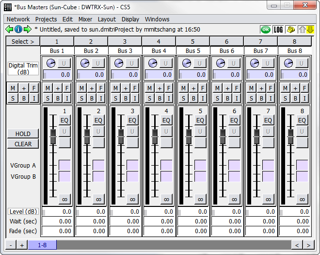
Bus Masters Window
Bus channel strips feature the following controls.
Control | Function |
|---|---|
Channel Select button | Channel Select is labeled with the associated bus number. Click to select a channel. |
Bus Label text box | This text box is used to change the name of the bus label. Any labeling changes made here are also reflected in the Matrix window. |
Digital Trim knob | Adjusts the trim. The adjacent U button resets the knob to unity. |
Set of automation controls | These controls are explained in Inputs Window. |
Set of fader controls | These controls include a fader slider, Unity button, Virtual Group assigns, HOLD and CLEAR buttons, and Level, Wait, and Fade value boxes. |
Output Masters
The Output Master faders control the audio signal mixed from the matrix channels assigned to each output.
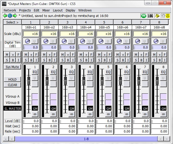
Output Masters Window
The Output Masters controls contain the following.
Control | Function |
|---|---|
Channel Select button | Channel Select is labeled with the associated output number. Click to select a channel. |
Output Label text box | This text box is used to change the name of the output label. Any labeling changes made here are also reflected in the Matrix window. |
Analog Scale setting | This adjusts the scale of the output signal. |
Digital Trim knob | Adjusts the trim. The adjacent U button resets the knob to unity. |
Set of automation controls | These are explained in Inputs window. |
Set of fader controls | These are described in Fader level control. |
G. Master button | When enabled, the Output Master is controlled by the Grand Master. When disabled, the Output Master remains independent. |
AUX Masters
The Aux Masters window displays controls for auxiliary output channels:
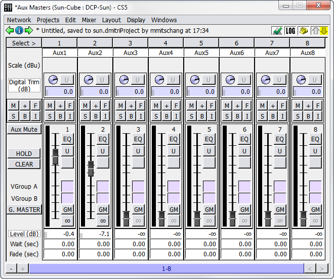
Aux Masters Window
The auxiliary output channel controls contain the following.
Control | Function |
|---|---|
Channel Select button | The button is labeled with the aux output number. |
Aux Output Label text box | Shows the aux output location. |
Analog Scale setting | Adjusts the scale of the output signal. |
Digital Trim knob | Adjusts the trim. The adjacent U button resets the knob to unity. |
Set of automation controls | These are explained in Inputs Window. |
Set of fader controls | These are described in Fader Level Control |
G. Master button | When enabled, the Output Master is controlled by the Grand Master. When disabled, the Output Master remains independent. |
Listen Masters
The Listen Masters window displays controls for Listen output channels.
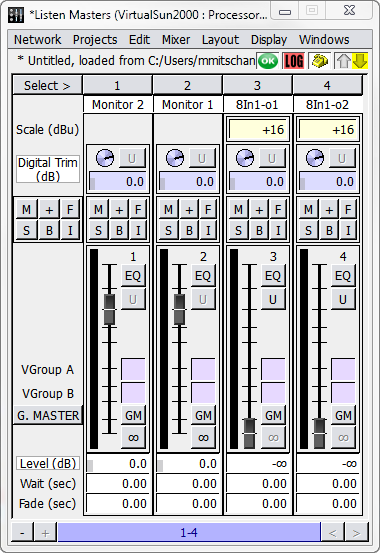
Listen Masters Window
The Listen Masters controls contain the following.
Control | Function |
|---|---|
Channel Select button | The button is labeled with the aux output number. |
Listen Name text box | Shows the Listen output location. |
Analog Scale setting | This is to adjust the scale of the output signal. |
Digital Trim knob | Adjusts the trim. The adjacent U button resets the knob to unity. |
Set of automation controls | These are explained in Inputs window. |
Set of fader controls | These are described in Fader level control. |
G. Master button | When enabled, the Output Master is controlled by the Grand Master. When disabled, the Output Master remains independent. |
Virtual Groups
The values of arbitrary groups of faders can be scaled by Virtual Group faders, also known as VGroups. A single Virtual Group fader can be assigned to control many types of faders at the same time. Any number of Input faders, Bus Master faders, Output Master faders, and Aux Master faders can be assigned to the same Virtual Group fader. Each fader can be assigned to two Virtual groups, allowing even more control.
The Virtual Groups window provides controls for VGroups.
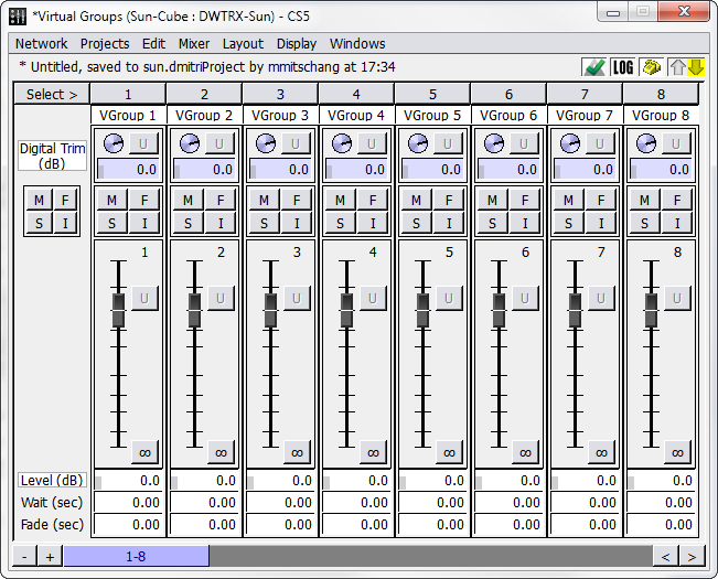
Virtual Groups Window
The Virtual Groups window contains the following controls.
Control | Function |
|---|---|
Channel Select button | The button is labeled with the VGroup number. |
VGroup Label text box | Shows the associated virtual group. |
Digital Trim knob | Adjusts the trim. The adjacent U button resets the knob to unity. |
Set of automation controls | These are explained in Inputs window. |
Set of fader controls | Includes a fader slider, Unity button, and Level, Wait, and Fade controls. |
Grand Master
The Grand Master is the final set of gain stages within CueStation. It controls the level of all outputs that have the GM (Grand Master) button engaged.
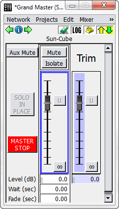
Grand Master Window
The Grand Master window contains the following controls.
Element | Description |
|---|---|
Aux Mute button | When active, mutes all Aux sends. |
SOLO IN PALCE button | Turns green whenever a solo is active. Click the button to clear the solo. |
MASTER STOP button | MASTER STOP has the same function as the Master Stop button in the Transport window: click the button to stop all automation, including Wild Tracks, SpaceMap trajectories, fades, wait times, and autofollows. |
Mute button | Mutes the audio on all main output channels. |
Isolate button | Isolates the Grand Master level, trim, and mute from automation. |
Grand Master fader | Provides Unity and -inf shortcut buttons |
Level, Wait, and Fade value boxes | These apply to the Grand Master fader. |
Trim fader | Provides Unity and -inf shortcut buttons. |
Level value box | For the Grand Master fader. |
Matrix window
The matrix in CueStation is an adaptation of a matrix found on traditional analog consoles. It performs distribution of bus signals to output channels.
Bus and Output controls
Bus and Output controls are displayed as a matrix, with level shown at each intersection.
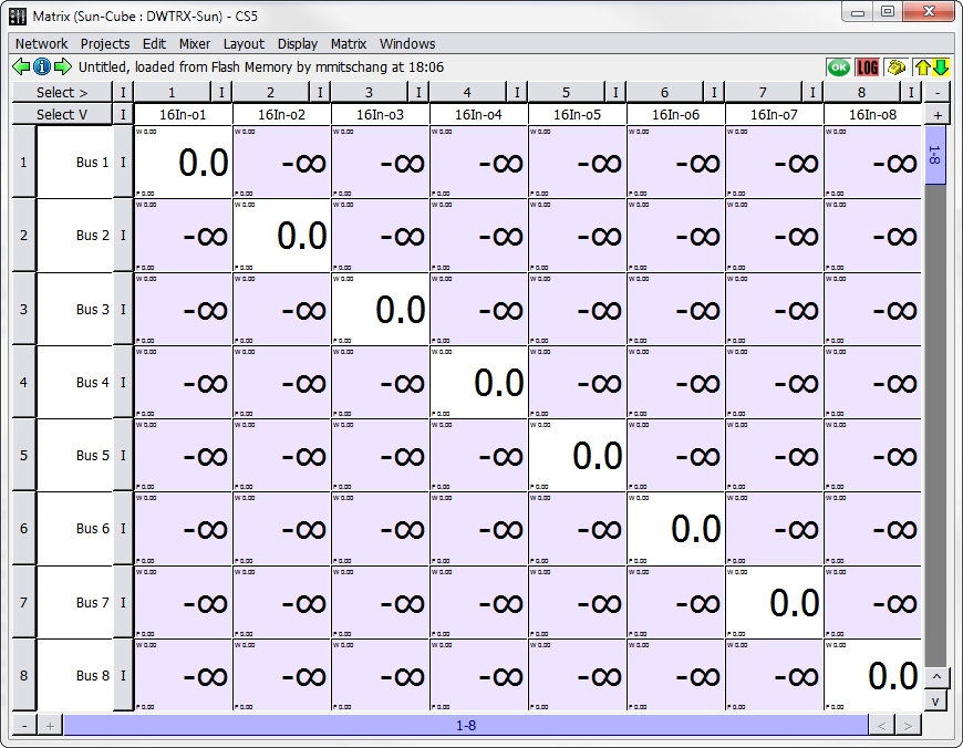
Matrix Window
Rows correspond to buses, and columns, to output channels. Along the left and top of the matrix display are corresponding control strips of Channel Select buttons. These are labeled with their Bus Number or Output Channel Number and names.
The rest of the matrix is devoted to cross-point value boxes, which correspond to the knobs on a physical console matrix. These value boxes can be adjusted by typing in a value directly, or by clicking box and dragging the value up or down. Levels are measured in dB (0 dB = unity).
Display menu
The following table describes the Matrix window Display menu commands.
Command | Description |
|---|---|
Show Waits | Displays the wait time at each crosspoint. |
Show Fades | Displays the fade time at each crosspoint. |
Show Levels | Default view. Displays the levels at each crosspoint. |
Show Vgroups A | Shows crosspoint VGroup A assignments. Drag a crosspoint to assign a VGroup. |
Show Vgroups B | Shows crosspoint VGroup B assignments. Drag a crosspoint to assign a VGroup. |
Show All | Displays all levels, wait time, and fade time in each crosspoint. |
Vertical Column Labels | Displays the destination labels in vertical text. |
Adjust Markup | Displays the Markup Palette, menu, and selection field. |
Show Page Group Controls | Displays Page Group controls at the bottom of the window. See Page Group Controls for more information. |
Matrix menu
The following table describes the Matrix Window Matrix menu commands.
Command | Description |
|---|---|
Clear Output Matrix | Set all levels to -inf dB. |
Clear Displayed Region | Set all levels on the currently displayed crosspoints to -inf dB. Levels that are not visible in the current Matrix window remain unchanged. |
Set Diagonal | The crosspoint of each bus and corresponding output is set to 0.0 dB, creating a 1-to-1 relationship between buses and outputs. |
Set Diagonal in Displayed Region | The crosspoint of each bus and corresponding output is set to 0.0 dB, creating a 1-to-1 relationship between buses and outputs. Levels that are not visible in the current Matrix window remain unchanged. |
Set Diagonal, Buses, Outputs | Sets a diagonal as explained above, and sets all Bus Masters and Output Masters to 0.0 dB. |
Matrix crosspoint color
Matrix crosspoint color changes to reflect which control point is currently shown.
Control Point | Color |
|---|---|
Waits | Pink |
Fades | Yellow |
Levels | Purple |
VGroups A | Orange |
VGroups B | Cyan |
Signal Processing controls
From top to bottom, Signal Processing windows consist of a channel select button, channel name display, an equalizer graph, a row of equalizer band controls, and a collection of text fields and processing controls.
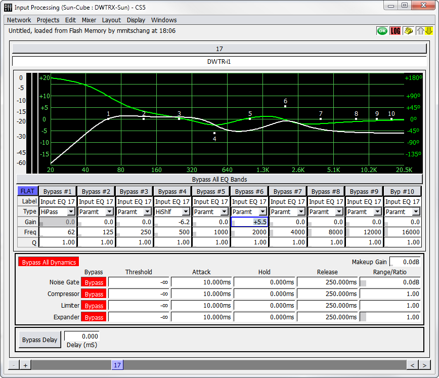
Signal Processing Controls (Input Processing Window Shown)
Processing controls for adjusting signal equalization, delay, and dynamics are available in the following windows:
Input Processing (shown below)
Bus Processing
Output Processing
Aux Processing
Listen Processing
VRAS Processing
Processing and channel strips
Channel strips in the signal processing windows contain the following components, from top to bottom.
Component | Function |
|---|---|
Channel Select button | Each button is labeled with the Channel Number. Selecting a channel in the Processing window is equivalent to selecting the channel in its corresponding displays gain reduction due fader window. |
Channel Label box | Faders can be automatically named when configuring the mixer. Click the text box and enter a custom name. |
Two signal meters | Meters display signal level to the left of the equalizer graph; one meter for channel level and another that displays gain reduction as a result of dynamics processing. |
Bypass All EQ Bands button | Disables EQ for the channel. |
EQ band controls | Bypass button. When selected, the corresponding equalizer control point is disabled. |
Band Label text box. | |
EQ Type selector. Contains various equalization algorithms (Parametric, Low Shelf, High Shelf, Notch, Low Pass, High Pass, and Band Pass). | |
Gain, Freq, and Q value boxes. Drag values up or down to change them. Val- ues can also be entered manually. The Gain value is disabled for Notch, Low Pass, High Pass, and Band Pass filter types. |
Component | Function |
|---|---|
Dynamics band controls for Noise Gate, Compressor, Limiter, and Expander | A Bypass All Dynamics button, for disabling all of the band dynamics at once. |
Bypass buttons to bypass selected dynamics processing: Noise Gate, Compressor, Limiter, and Expander. | |
Threshold, Attack, Hold, Release, Range/Ratio, and Makeup Gain value boxes. Adjust by dragging or by typing a value directly. | |
Delay controls | Bypass Delay button. Disables the delay on that channel. |
A Delay value box. Enter 0 to disable delay for the channel, or a decimal value to set delay in milliseconds. |
Tip
To make changes in smaller increments, hold down the Option/Alt key when dragging values. Page Up and Page Down keys can also be used to make incremental changes.
Display menu
The following table describes the commands available in the Display menu of the Input Processing and Bus Processing windows.
Command | Description |
|---|---|
Show EQ Graph | Display visual representation of frequency and gain. |
Show EQ Phase | Display green phase line behind the EQ graph line. |
Show EQ Band Settings | Display controls for all EQ processing. |
Show Delay Settings | Display controls for delay processing. |
Show Delay Distances | Display delay as distances, in both feet and meters. Changing the time field affects the distance field, and vice versa. |
Show Dynamics Settings | Display controls for dynamics processing. |
Show Meters | Display signal and compression meters. |
Show Peak Hold | Display Peak Hold mark. |
Set Peak Hold Duration | Enter a time for the Peak Hold mark to remain visible. |
Show User CSV Traces | Display user-added graph data. |
User CSV Trace Settings | Import a file to create an additional EQ trace. |
Show Page Group controls | Display Page Group controls at the bottom of the window. See Page Group Controls, for more information. |
Keyboard and mouse commands
Processing controls can be navigated and edited in multiple ways.
Arrow and Tab keys navigate the various value boxes.
Hold down Shift when changing a value to adjust channels as stereo pairs.
Hold down Option (Mac) or Alt (Windows) when changing a value to make smaller changes.
Right-click a control point value and drag from one channel to another to copy the setting.
Drag EQ points in the EQ graph to adjust Frequency (X axis) and Gain (Y axis). Hold Shift while dragging to adjust channels in pairs.
Right-click and drag EQ points in the EQ graph to adjust Q (X axis) and Gain (Y axis). Hold Shift while dragging to adjust channels in pairs.
Tip
To adjust an arbitrary number of channels at once, click the channel select buttons for multiple channels and hold Command (Mac) or Ctrl (Windows) while adjusting control points. To adjust values relatively, hold Command+Option (Mac) or Ctrl+Alt (Windows).
User Traces
When configuring EQ settings, it can be helpful to view a reference trace in addition to the actual processing trace. Traces can be added in the form of CSV files. There are several programs that can output EQ data as a CSV file, such as Matlab or SIM3.
In the Input Processing window, choose Display > User CSV Trace Settings.
Click Choose Directory, and then navigate to the directory where the trace files are stored.
Click Choose File to choose a CSV file. The CSV data is now visible in the EQ graph. If not, adjust the Gain Offset up or down until the trace is visible.
Click Color to select the display color of the trace.
To view multiple traces at once, click Add Another Trace and follow the same steps. A different color can be assigned to each trace.
Channel-specific traces
Adding a user trace typically results in the same trace being visible on all channels. Different traces can be assigned to different channels by using a specific file naming technique.
To assign traces to specific channels:
Rename the CSV files with the same prefix, and append each with an underscore followed by the channel number. For example:
Trace_25.csv
Trace_26.csv
Trace_27.csv
In the User CSV Trace Settings window, click Choose Directory and navigate to the directory where the trace files are stored.
In the File text box, type
Trace_%CHAN%.csv. CueStation automatically replaces the
%CHAN% text with the channel number. This means that Trace_25.csv appears only on channel 25, Trace_26.csv appears only on channel 26, and so on.
Monitoring D-Mitri systems
CueStation provides several ways of monitoring the activity and health of D-Mitri systems, including connection status indicators in the bottom corner of every window. There are also several windows dedicated to providing feedback about the state of the system.
CueStation connection status
When CueStation is connected to a server, the name of that server is displayed in the title bar of every CueStation window, next to the window title. This makes it easy to tell whether the CueStation client is connected or not. One basic method of monitoring network activity exists in every CueStation window as a status bar.
Status Bar
The two arrows in the status bar are communication status arrows. The upward (upload) arrow represents communication from CueStation to the server, and the downward (download) arrow represents communication from the server to CueStation. The arrows are gray unless there is active communication between the window and the server, in which case they turn yellow or green.
An arrow's background color also carries meaning. A yellow background, for example, indicates that metering has fallen back to TCP as a result of UDP packet loss. In the case of a window failing to receive a response from the server for four seconds, the background of the downward arrow changes color, as shown below.
In tandem, the color of an arrow and its background show which server background process is not responding. MixerD is the D-Mitri process that manages mixing functions; CueD is the D-Mitri process that manages cue functions.
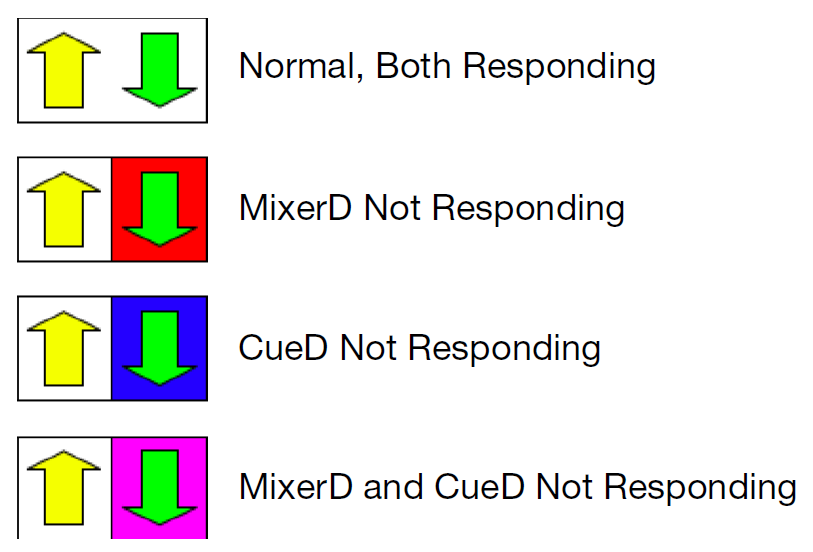
Status Arrows and Associated Connection Status
Click the communication status arrows to open the System Status window, where more complete system information is displayed. For more information, see System Status Window.
Log alert, Page alert, and Status alert
To the left of the connection status arrows, there are three icons: a System Status icon, a telephone, and a LOG icon.
The System Status icon shows a green OK symbol when CueStation is running normally. It shows a red blinking background during a Critical level Alert condition, and a yellow background during a Warn level Alert condition. Click this icon to bring up the System Status window. To change the threshold for system status alerts, right-click this icon when the System Status window is up. Select the threshold from the menu. For example, when selecting Alert on Critical Error Condition, the system status icon only blinks when a Critical Error occurs.
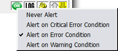
Whenever a log entry of Warning level or higher is printed to the log, the LOG icon flashes the corresponding color on all connected CueStation windows. Click the icon to open the Log window and clear the flashing.
Similar to the system status threshold, the threshold of log alerts can be changed by right-clicking the LOG icon. For example, if Blink on Critical Error is selected, the LOG icon only blinks when a Critical Error message appears in the log. See Log window, for more details about error messages.
 |
Log Alert Threshold
The telephone icon allows quick access to the Chat window. When one user pages another, the recipient’s CueStation windows flash cyan once, and the telephone icon continues to flash until the Chat window is opened. Hovering the mouse over the telephone icon shows a tooltip that displays the last several page instances with timestamps.
Log window
The CueStation log records all important system messages, both from CueStation and from D-Mitri modules. It provides a useful tool for troubleshooting hardware issues, communication problems, configuration errors, and cue automation issues. CueStation stores logs as files in the D-Mitri_Logs directory, within the CueStation_Settings directory. CueStation creates a new log for each session, and incorporates date and time stamps into the name of each log file.
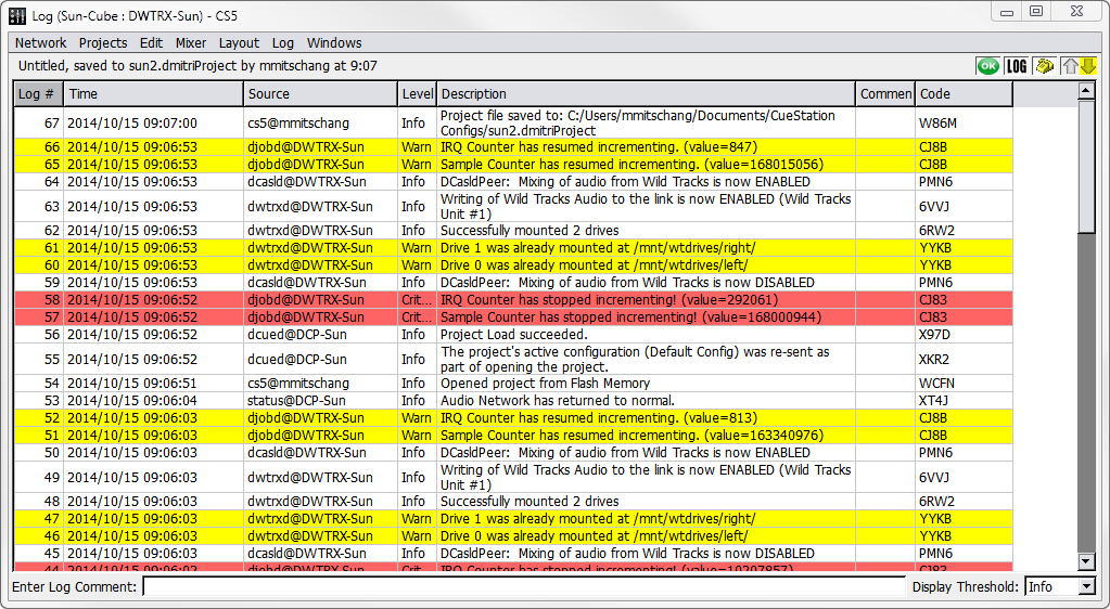
Log Window
Log entries
Click a column heading to sort the log in ascending order by that heading; click the heading a second time to sort it in descending order. Column sorting is indicated by a triangle icon, when column width permits. Columns can be arranged by dragging them from one position to another within the table.
The Log # and Time columns show the order in which the messages were received. The Source column indicates which software or hardware component sent the message, while the Level column shows the severity of the message and the Description contains the message. Log entries can be annotated in the Comment column. The Source Serial # column shows the serial number of the device CueStation read for each message. The Code column shows a code number associated with each log, useful for debugging and troubleshooting.
Adding log entries
The Log window also has an Enter Log Comment text field which can be used to easily enter comment lines into the log. The warning level of the comment entry can be set using the drop-down box to the right of the text box. Note that selecting an error level from the drop-down box also filters the error display to show only errors of the type selected.
To add an entry, type the comment into the Enter Log Comment text field and press Enter.
Types of log entries
There are six levels of log messages that might appear in the log window.
Level | Message Description |
|---|---|
Info | These messages contain information about normal system activity. This includes recalling a cue, or the completion of certain processes such as track-from-top or saving a project to flash. These messages have a white background. |
Warn | The Warn level is for messages that are important to note but do not necessarily indicate that an error has occurred (i.e., a version mismatch between the client and the server). These messages have a yellow background. |
Error | This level indicates that an error has taken place. Error messages do not necessarily mean that the system is in danger of failure. For example, an attempt to recall a nonexistent cue would be logged as an error, but such an occurrence does not jeopardize the function of any D-Mitri module or of a D-Mitri system. Error messages have a pink background. |
Critical | This level indicates a critical system failure. These messages have a red background. |
Debug | Debug messages contain debugging information only, and do not usually appear in normal CueStation operation. These messages have a green background. |
Trace | These messages are used to trace program execution and do not usually appear in normal CueStation operation. These messages have a cyan background. |
Log menu
The Log menu has several commands for managing the displayed messages.
Command | Description |
|---|---|
Enable Word Wrap | Continues each entry on a new line if the contents exceed the column width. |
Clear Log | Clear the log window of all log entries. This command clears the log for all CueStation clients connected to the target D-Mitri system, as opposed to clearing just the local Log window. |
Save Log | Save the log to a text file. |
Save Log As | Save the log to a text file, with a different file name. |
Save All Processor Logs | Save a single archive containing system log files for all D-Mitri processor modules. |
System Status window
The System Status window provides a remote view of the performance of D-Mitri modules included in the system configuration. Processor modules and Matrix modules are monitored in real-time.
Tip
Click the communication status arrows or System Status icon in any CueStation window to open the System Status window.
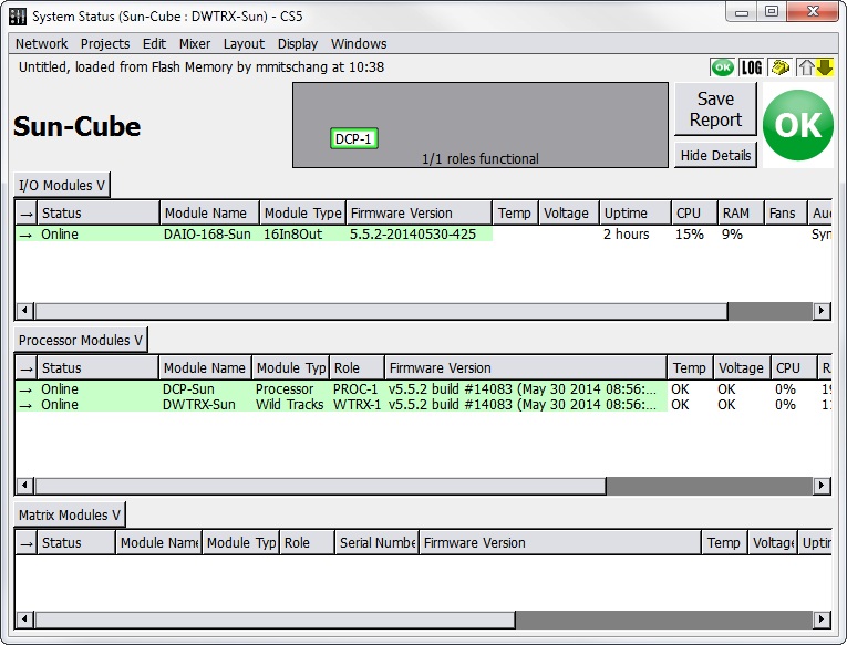
System Status Window
The window provides a live link state diagram, which displays which DCP modules are currently passing audio to which DCM modules. This diagram is particularly useful in operating D-Mitri systems containing redundant modules, as it shows which redundant modules are active.
Note
No system details are available when connected to VirtualD-Mitri. The System Status window shows no entries.
Under normal conditions, the entries display on a green background. The background color changes according to a unit's status. When D-Mitri is operating within its nominal range, OK is displayed for temperature, voltage, and fan speed. Error messages are displayed with detailed information if these values are outside expected ranges.
The following table describes the categories of data that appear in the System Status window.
Category | Description | |||||||||||||||||||
|---|---|---|---|---|---|---|---|---|---|---|---|---|---|---|---|---|---|---|---|---|
Status | Online or Offline. | |||||||||||||||||||
Module Name | Displays predetermined name. | |||||||||||||||||||
Module Type | Displays predetermined type. | |||||||||||||||||||
Role | Displays the role of a processor module as primary or backup. The role of a module as shown in the System Status window reflects its role as specified in the Mixer Configuration window, with minor differences in how some backup modules are denoted. Modules are presented in the Role column of the System Status window as shown below, with the corresponding name for each module as it is displayed in the Unit column of the Mixer Configuration window.
| |||||||||||||||||||
Serial Number | Module serial number. | |||||||||||||||||||
Version | Version and build information. | |||||||||||||||||||
Temp | If the temperature is outside the maximum working limits by 5% or less, the background is yellow with black text. If greater than 5% outside the working limits, the background is red with white text. | |||||||||||||||||||
Power | If the voltage is less than 5% of the working value, the background is yellow with black text. If greater than 1% over the working value, the background is red with white text. | |||||||||||||||||||
Uptime | How long the system has been active. Time is given in increments ranging from seconds to days. | |||||||||||||||||||
CPU | Percentage of CPU used. | |||||||||||||||||||
RAM | Percentage of RAM used. | |||||||||||||||||||
Fan Speed | Shows OK when fans are working properly. Displays an error in the event of a fan malfunction. | |||||||||||||||||||
Synchronization | Shows the difference between each module's system clocks. There should never be more than a few milliseconds in a properly functioning system. If the values go out of range, an error is written to the log. | |||||||||||||||||||
Audio Port Status | Shows which GNet audio connections (between a DCP and a DCM) are in use, down, or missing. Indicates which module is currently serving as the PTP Best Master Clock. | |||||||||||||||||||
FPGA Version | Displays the version of the FPGA firmware that a module is running. Note that I/O modules do not use FPGA firmware. |
Tip
To download all Engine Logs to a client computer, right-click a table background in the System Status window and choose Download all Engine Logs.
Recommended maximums
D-Mitri hardware may not function properly if any of the following temperature or voltage thresholds are exceeded.
Threshold Type | Maximum Values |
|---|---|
Temperature | Core1 through Core4: warn at 60ºC/140ºF, error at 72ºC/162ºF. MCH: warn at 90ºC/136ºF, error at 100ºC/212ºF. FCC: warn at 65ºC/150ºF, error at 75ºC/167ºF. CB: warn at 55ºC/131ºF, error at 75ºC/167ºF. |
Voltage | in0: expected is 1.8v, warn at ±5%, error at ±10%. in1: expected is 1.1v, warn at ±22%, error at ±23%. in2: expected is 3.3v, warn at ±5%, error at ±10%. in3: expected is 5.0v, warn at ±5%, error at ±10%. in4: expected is 12.0v, warn at ±5%, error at ±10%. in5: expected is 1.1v, warn at ±5%, error at ±10%. |
Channel meters
The meters provide real-time metering of Input, Output, Bus, and Aux signals. Input is scaled to trim levels. PAFL channel meters are displayed in the Aux Meters window.
The Input Meter itself, examples of which are shown in the image below, shows signals in the range -90 dBFS to 0 dBFS.
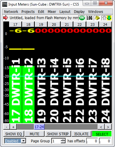
Input Meters Window
The meter scroll bar functions the same as blue scroll bars in other windows: The horizontal scroll bar has + and - buttons to add or remove channel strips from the window, as well as and buttons to scroll through the strips when they don’t all fit in the window.
Peak hold indicator behavior can be adjusted. Choose Display > Set Peak Hold Duration to change the peak hold time.
Choose Display > Show Peak Hold Bar to display a bar that indicates the peak level for the chosen duration.
Choose Display > Show Peak Hold Text to display the currently-held peak level of that channel in text above the meter.
Choose Display > Show Reference Line to display a horizontal reference line at a set level. The reference line defaults to -20 dB. Choose Display > Set Reference Level to set a cus- tom reference value in decibels.
Tablet controls
The Meter windows have additional channel editing controls, accessible through the Display menu. These controls are particularly useful for tablet/touch screen displays, but can also be used with a regular mouse.
When Display > Show Tablet Controls is enabled, the following five buttons are displayed across the bottom of the window.
Control | Description |
|---|---|
Show EQ | When the Show EQ function is active, touch or click a meter to open the corresponding channel processing window. This allows quick access to EQ, dynamics, and delay controls. |
Mute | When the Mute function is active, touch or click a meter to mute that channel. |
Show Strip | When the Show Strip function is active, touch or click a meter to open the corresponding mixer window, with the selected channel in the first column. |
Isolate | When the Isolate function is active, touch or click a meter to isolate that channel. |
Select | When the Select function is active, touch or click a meter to select that channel. Several channels can be selected at one time. |
UDP metering
CueStation's default metering setting is UDP multicast packets. UDP packets are multicast by the D-Mitri, and all of the clients listen to receive the metering information. This allows the meters to update faster and be more accurate. If network problems are encountered with metering, switch back to TCP metering by disabling Network > Use UDP Metering.
Display menu
The Metering windows contain a Display Menu, which provides the following commands.
Command | Description |
|---|---|
Show Meter Levels | Displays green meter bars. |
Show Compression | Displays compression activity. |
Show Names | Displays channel names. |
Show Channel Selects | Shows the Channel Select buttons. |
Show Horizontal Meters | Switches meters from vertical to horizontal array. |
Show Grid Lines | Displays horizontal grid lines that correspond with the decibel level markings. |
Show Reference Line | Displays a horizontal reference line at a set level. The reference line defaults to -20 dB. |
Set Reference Level | Sets a custom reference value in decibels. |
Show Peak Hold Bar | Shows a peak hold bar for each channel. |
Show Peak Hold Text | Displays current dB value of peak hold. |
Set Peak Hold Duration | Opens a dialog box to set the amount of time peak hold bars remain visible. |
Show Tablet Controls | Enables Tablet controls. See Tablet Controls, for more information. |
Show Channel Test Controls | Displays Channel Test controls above the meters. See Testing with Internally Generated Signals, for more information. |
Show Page Group Controls | Displays group controls. See Page Group Controls, for more information. |
CueStation automation
CueStation mixer automation governs the movement of mixer controls over time. It provides transition automation, which allows for fades and other changes over time, as compared to simple snapshot automation, which typically sets all controls instantaneously.
CueStation offers a graphical interface for various mixer control points. A control point is any adjustable mixer control, such as a fader, pan knob, or EQ setting. The values for a set of control points are contained in a subcue and a set of subcues can be captured to create a cue. These cues can be placed in a cue list. During a show, the cues in the cue list can be recalled manually, automatically in sequence, at a certain time point, or via a controller external to the system.
Control hierarchy
The subcue, cue, and cue list structure provides a system for defining control automation. The complete CueStation data hierarchy, from the bottom up, is as follows:
Control Points
A control point in CueStation is defined in a general sense as any parameter that can be adjusted manually or by the automation system. As with physical consoles, a lot of the control points are associated with faders, knobs, and switches. Some control points address signal processing parameters, such as equalization and delay, while other control points, like isolate, affect the operation of the automation system itself.
For example, Input faders have three control points: Level, Wait, and Fade. Level sets the target fader value, and Fade sets how long the fader takes to move to the target value. Wait sets the delay between recalling the cue and the start of the fader movement. This allows one to program a cue that starts a three-second fade to unity one second after recall. All three control points are contained in each Input Level subcue.
Subcues
A Subcue is a collection of control points. The automation structure in CueStation is based on absolute destinations. Control points contained in subcues dictate the state the mixer once the recall of that subcue is complete, regardless of what those control points were set to when the subcue was recalled. For example, if a subcue is recalled with the information Input 10 Level: -20.0 dB Fade: 5 Wait: 0, the fader moves from its current position to -20 dB over five seconds.
Control points can be set as relative values within the subcue structure definition. For exam- ple, a subcue can be defined that increases or decreases an input level. This is achieved by entering the value using a prefix to indicate the relative increase or decrease. The prefix for specifying a relative increase is ++, and the prefix for specifying a relative decrease is --.
Cues
A Cue in CueStation refers to a list of subcues that are recalled as a group. A cue could contain many different types of subcues, or only one subcue. If a subcue has a wait time associated with it, that information is also stored as part of the cue. The same Subcue can appear multiple times in a Cue, and in multiple Cues.
Cue Lists
A Cue List is an indexed collection of cues that are intended to be recalled in a certain order. Like a cue, a cue list does not have any control point data in itself. It merely contains references to the cues associated with it. A cue list can also have recall and timing information associated with each cue (see Building a Cue List). The same Cue can appear multiple times in a Cue List, and in multiple Cue Lists.
Project File
The Project File is the container that stores all automation data. A project file also contains the configuration of the hardware, layout information, and connection settings. Any of the data in a project file can be merged into another project; this provides a method for importing cues, cue lists, or any other automation data. Project files can be saved to a client computer's hard drive, or to the flash memory inside a D-Mitri. Projects saved to a hard drive have a dmitriProj- ect extension.
Note
D-Mitri's flash memory saves only one file across all the processor modules in the system. Choosing Projects > Save Project to Flash overwrites any existing project file already saved in the flash memory of D-Mitri processor modules.
Cue-based automation
Control point settings are stored and organized through the automation editing windows. These windows support the creation and management of subcues, cues, and cue lists. Subcues contain the control data for all mixer functions and external device commands.
CueStation stores discrete states, target values, and time intervals, and calculates the continuous transformations from cue to cue on the fly. Such efficiency is essential for large configurations. The flexibility of cue automation is also critical in live performance where timing and order can not be accurately determined ahead of time.
Automation basics
This section summarizes the process of capturing cues into a cue list. Each of these steps is explained in more detail in subsequent sections.
Set Control Points. The first steps in creating a cue are determining what the cue should do and setting the control points on the mixer accordingly. Because of the way automation works in CueStation, set the mixer to the state it should be in once the cue is complete. For example, to program an input fader to fade from 0 to -20 dB over five seconds, set the fader to -20 dB, then set the fade time to 5.
Select Channels. Once the mixer is set to the desired state, use Channel Select to filter which parts of the mixer to capture into the cue. For instance, to achieve a fade out of input channels 5 and 6 without changing the level of the other input channels, select only channels 5 and 6. Channel Select is described in more detail in Channel Select.
Open Capture Window. When the control points have been set and the appropriate channels have been selected, press the F4 key to open the Capture window. In the Capture window, enter a name and comment for the cue. The cue-capturing process is described further in Capturing Cues.
Select Subcue Types. The next step is determining which parts of the selected channels to capture. In the middle of the Capture window there are several lists of subcue types; place a check mark next to each subcue type to be captured, and leave the rest unchecked. For example, to capture the input levels while leaving the input labels unchanged, check the box next to Input Levels and uncheck the box next to Input Labels.
Capture Cue. Once all the relevant subcue types have been selected, click the button in the lower right corner labeled Click to Capture New. A new cue is created with the chosen name, referencing the subcues that were selected. The new cue is appended to the current Cue List, and also appears in the Cue Library. The new subcues appear in the Subcue Library.
Build a Cue List. After cues have been created, they can be organized into a Cue List within the Cue List window. To add more cues from the Cue Library window, right-click them and drag them into the Cue List. Right-click and drag to change the order of existing cues in the Cue List. Cues can be set to recall manually or by timecode from within the Cue List window or by auto-following a previous cue by a certain length of time. See Building a Cue List for more information.
Edit Cues. There are several ways of editing cues after they have been captured. One way is through the Capture window, in Capture Differences mode. Instead of creating a new cue with the selected control points, it amends the changes to the most recently recalled cue, or any other selected cue. Another way to change a cue is to edit the values of the control points manually, by viewing the contents of the subcues. These methods are described more fully in Editing Cues.
Channel select
Each of the mixer windows displays a group of channels or controls that are all of the same type, whether they are input channels, output channels, Wild Tracks Decks, SpaceMap buses, etc. All the information can be captured from all the channels at once in a single subcue. By using Channel Select, only information from the channels that need to change is captured in a particular cue.
The mechanics of Channel Select also apply to Wild Tracks Deck and SpaceMap trajectories. For a cue that starts an audio file playing in one deck, capturing only that deck prevents the cue from interrupting other decks.
Using Channel Select in each window
At the top of or beside all channel, bus, and virtual group controls, CueStation offers a button labeled Select, adjoined by an arrow pointing across the channel strip columns to the right. Click this Master Select button to select all channels in the window, highlighting the channels.
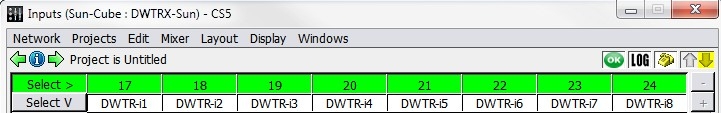 |
Master Select Button (Inputs Window Shown)
For greater convenience in selecting large numbers or non-contiguous ranges of channels, right-click the Master Select button to open the Selects dialog, as shown below.
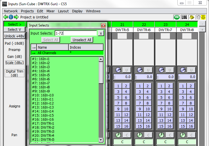 |
Selects Dialog (Input Selects Shown)
Channels can be selected from this list without having to scroll through the window to choose channel strips through mouse selection. Click a channel in the list to select it, or enter channel numbers in the text field above the list. The text field recognizes both individual channels and ranges of channels. Ranges of channels are specified by separating the first and last channels of the range with a dash.To input multiple selections, separate them using commas. For example, entering 1-7,12,24-29 selects channels 1 through 7, channel 12, and channels
24-29.
The Capture window has controls that further refine Channel Select. To show which channels are being captured, click the Use Channel Selects button. Each type of channel has a check- box that can be deselected to capture all channels instead of just the selected ones.
When a cue that uses Channel Select is captured, the new subcues that are created only con- tain information about those controls that were selected. Later, when that cue is recalled, only those selected channels are affected. All other controls continue to do whatever they were doing. If a channel is in mid-fade, it continues to fade; if at rest, it remains at rest.
Using Channel Select in the Capture window
It is also possible to edit channel selects from within the Capture window. This is especially useful when for selecting multiple channels from different areas (Wild Tracks, SpaceMaps, Aux, etc.).
Right-click the Channel Selection area (see “Channel Selection” on page 85), To the right of the Channel Select buttons, to open the pop-up editor.
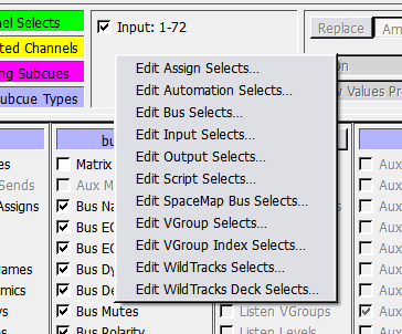 |
Select the channel type from the list to bring up the control dialog.
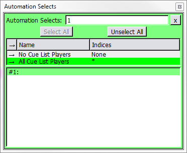 |
Select the channels to capture, then click the close box in the upper right corner to close the dialog.
Repeat the process for every different channel type to capture. The channels are now selected in the Capture window.
Channel select capture logic
In most mixer windows, control points for all channels are captured if no channels are selected. For example, capturing an Input Level subcue while no Input channels are selected results in a captured subcue that includes the levels of all Input channels.
There are a few exceptions:
If the Wild Tracks Deck subcue type is selected, but no Wild Tracks Deck is selected, then only Deck 1 on Unit 1 is captured into the cue.
If the SpaceMap Trajectory or Position subcue type is selected, but no SpaceMap bus is selected, then the captured SpaceMap subcue contains no control points.
If the Cue List Player subcue type is selected, but no Cue List Player is selected, then the captured Cue List Player subcue contains no control points.
Follow Channel Selects
When Mixer > Follow Channel Selects is enabled, recalling a cue that contains Channel Selects automatically selects the associated channels in the mixer windows.
Note
This function is enabled only on a per-client basis, and assists with troubleshooting programmed automation. It is recommended to leave this function off, as it can sometimes cause a cue to capture a different set of items than intended.
Capturing cues
The Capture window is where the actual cue and subcue creation takes place. The Capture window controls make it easy to limit the control points and channels to be captured, and to create a new set of subcues corresponding to only those control points that have been changed.
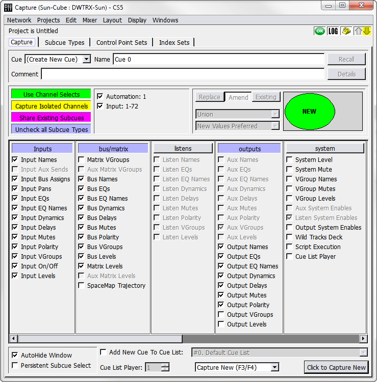
Capture Window
Capture window controls
The Capture window has four tabs: Capture, Subcue Types, Control Point Sets, and Index Sets. The latter three tabs allow customization of the set of control points captured for a subcue, or create new subcue types. These tabs are detailed in Capture Window Tabs.
The Capture tab is the main working window for cue creation. There are five groups of controls:
A Cue Selection area, which identifies the source cue for Capture Differences or shows (Create New Cue) for Capture New. It also shows the new cue’s name and description.
A Channel Selection area, for selecting which channels are captured.
Capture Differences controls, active in Capture Differences mode, specify how new control points are integrated with the cue's current subcues.
A Subcue Types Selection area, identifying the set of mixer component controls to be captured.
A Capture Controls area, with options relating to the behavior of the Capture window and how the cues are captured.
Cue Selection
The Cue Selection area provides a set of controls to create new cues, update existing cues, or recall settings on which to base a new cue.
Capture Window, Cue Selection Area
The Cue Selection area contains the following controls.
Control | Function |
|---|---|
Cue drop-down box | Shows (Create New Cue) by default. By selecting an existing cue from the drop-down box, the subcues can be updated or replaced. |
Name text box | Shows the name of the selected cue. A name can be entered for the new cue, or edited for the selected cue. |
Recall button, | Triggers the cue, moving its control points to their previously-saved values. |
Comment text box | A place to type any comments regarding the cue. Comments are saved with the cue and are visible from the Cue Library, Cue List, and Transport. |
Details button | Opens the Cue Library to show the current cue’s subcues. |
Channel selection
The Channel Selection area controls the selection of channels to be included in the cue.
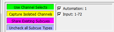
Capture Window, Channel Selection Area
The Channel Selection area contains the following.
Control | Function |
|---|---|
Use Channel Selects | Button specifies whether the captured subcues include values for all channels, or only selected channels. |
Channel Selection Range | Checkboxes appear to the right of Use Channel Selects. The channels selected via Channel Select are shown, some of these sets can be turned off to further refine the channels that are included in the subcues. |
Capture Isolated Channels | Button specifies whether channels that are isolated are to be captured or not. |
Share Existing Subcues | Share Existing Subcues is active by default. When inactive, new cues never use the existing subcues. Instead, a new subcue is created for every checked subcue type. |
Uncheck All Subcue Types | Unchecks all subcue types in the Subcue Types Selection area below. |
Capture Differences controls
This section is only active for Capture Differences or Update Subcues, and controls how the intersection between the new and old subcues is handled.
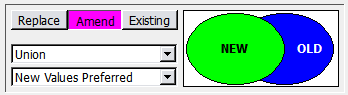
Capture Window, Capture Differences Section
The Capture Differences area contains the following.
Control | Function |
|---|---|
Mode buttons | These buttons, Replace, Amend, and Existing, toggle between the three most fre- quently used update modes. |
Capture-Operator | This box offers four options: New Control Points Only, Intersection, Union, and Old Control Points Only. |
Capture-Precedence | This box offers three options: New Values Preferred, Old Values Preferred, and New Values Always. |
Venn Diagram | Provides a graphical depiction of how the subcues are updated. |
These controls are described in detail in Capture Differences and Update Subcues.
Subcue Types Selection
The Subcue Types Selection area controls the selection of subcue types to be included in the cue.
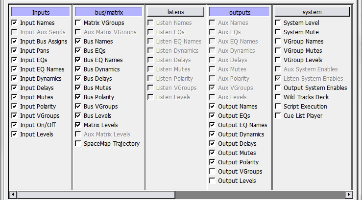 |
Capture Window, Subcue Types Selection Area
This is divided into sections by category. Each section contains:
Category labels, such as Inputs or Trim. Clicking a label selects or deselects all the subcue check boxes within that category.
A list of Subcue Types. Each selected subcue type is included in the cue.
The lists are grouped according to their subcue type category, as defined on the Subcue Types tab.
Capture controls
At the bottom of the Capture window are additional options that modify the behavior of the Capture operation.
Option | Function |
|---|---|
AutoHide Window checkbox | If this checkbox is checked, then the Capture window closes automatically when the Capture button is clicked. The window can be restored by pressing the F4 key, or by selecting Windows Capture. |
Persistent Subcue Select checkbox | If this checkbox is checked, then the last subcue types captured are automatically selected the next time the Capture window is opened. |
Add New Cue to Cue List checkbox and a Cue Lists selector | When the checkbox is enabled, the captured cue is added to the selected cue list in addition to the cue library. |
Capture Type menu | Capture New captures a new cue according to the set parameters (cue name, channel automations, and subcue types). |
Capture Differences causes new subcues of the same types included in the selected cue to be created and referenced in the cue. | |
Update Subcues causes the information in existing subcues to be changed, thus allowing global changes to be made. |
The Capture Differences and Update Subcue functions are described in Editing Cues.
Note
The function keys F1 through F4 open the Capture window. Each key opens the window in a different mode:
F1 opens the Capture window in Update Subcues mode, and selects the last cue that was recalled.
F2 opens in Capture Differences mode, with the last cue recalled selected.
F3 opens in Capture New mode, but does not add the new cue to the cue list.
F4 opens in Capture New mode, and adds the cue to the cue list.
When pressing the Fn key while viewing the Cue List or Cue Library window, Capture opens to the currently-selected cue. Otherwise, it opens the most recently recalled cue. Using F4 sets some of the capture controls automatically.
Capture windows tabs
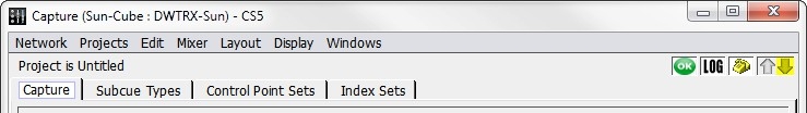
Capture Window Tabs
The Subcue Types tab
The Subcue Types tab lists a number of basic subcue types and custom subcue types.
Note
Modifying the default subcue types is not recommended. It is safer to use the Duplicate button and modify the duplicate copy instead.
Each of the standard subcue types captures a single control point set for all applicable chan- nels: the Input Level subcue captures the Input Level control set, the Aux Sends subcue cap- tures the Aux Sends control set, and so on.
Specialized subcue types can be created that capture any combination of control point settings on any number of channels. This is an advanced task, accomplished through the use of control point sets and index sets.
This tab has four main components: a set of command buttons, a list of subcue types, a list of control point sets, and a list of index sets.
Command buttons
The command buttons create or delete subcue types.
Button | Function |
|---|---|
New | Creates a new subcue type from scratch. The subcue type can be named, its category specified, its control point sets selected, and its index sets defined. |
Duplicate | Creates a new subcue type based on the selected subcue. The subcue type can be named, its category, parameter, and index sets can be fine-tuned. |
Delete | Deletes the selected subcue type. Any subcues that made use of this subcue type are changed, which in turn affect all cues that use that subcue. |
Subcue Types List
Click a column label to sort the entries alphabetically by the contents of that column. Click it again to sort them in reverse order. The format of the ID and Created dates are compatible with alphabetical sorting.
Column Data | Description |
|---|---|
ID | A system-assigned number that cannot be changed. |
Name | The subcue type value. The name can be changed by selecting it and typing a new name; subcues that used this subcue type also show the change. |
Category | Sorts the names according to type. Right-click the entry to select from the available types, or type a new name to create a new category. |
Display Order | The number determines the order in which the subcue types appear in the Capture pane of the Capture window. |
Comment | This field can contain any text. |
Created | Provides date of creation, and cannot be changed. |
Modified | Provides modification date, and cannot be changed. |
Enabled | Shows whether a subcue type has been enabled or disabled. Disabled subcue types do not appear in the Capture pane of the Capture window. Right-click the entry to toggle between enabled and disabled states. |
Locked | Shows whether a subcue type is locked or unlocked. |
Control Point Sets List
When a subcue type is selected, the control point sets associated with it are listed to its right.
Click the associated checkboxes to select control point sets to be included in the subcue. For control point set definitions, see The Control Point Sets tab.
Index Sets List
An index set is listed for each control point set that is selected. The column labels for this list can be clicked to sort the list alphabetically.
Right-click an Index Set entry to choose between Manual and any applicable custom index sets that have been defined.
When a Manual index set is selected, a list of channels can be typed in the Channels entry. Channels can be separated with a space or comma, ranges of channels can be selected by using a dash between numbers (1–4,6,8). To select all channels, use an asterisk (*).
The Control Point Sets tab
The Control Point Sets tab lists the standard preset control point sets and any custom control point sets that have been designed.
The Control Point Set is used by Subcue Types to identify which CueStation mixer compo- nents are captured in a subcue. The standard control point sets cover every common combi- nation of components. Input Levels, for instance, captures the channel invert, input level, and input mute settings.
Specialized Control Point Sets can be created that capture any imaginable combination of controls.
This tab has three main components: a set of command buttons, a list of Control Point sets, and a list of mixer control points.
Command buttons
The command buttons create or delete Control Point Sets or add to or remove Address Pat- terns from selected control points.
Command | Function |
|---|---|
New | Creates a new control point set from scratch. The new control point set can be renamed and its list of Address Patterns can be modified. |
Duplicate | Creates a new control point set based on the selected subcue. The new control point set can be renamed and its list of Address Patterns can be modified. |
Delete | Deletes the selected control point set. |
Add Pattern | Adds a new Address Pattern to the list. Right-click the entry to select from an extensive list of common Address Patterns. |
Delete Selected Patterns | Removes any selected Address Patterns from the list. |
Control Point Sets List
Click a column label to sort the entries by the contents of that column. Click it again to sort them in reverse order.
Column Data | Description |
|---|---|
ID | A system-assigned number that cannot be changed. |
Name | The subcue type value. The name can be changed by selecting it and typing a new name. |
Comment | This field can contain any text. |
Created | Provides date of creation, and cannot be changed. |
Modified | Provides modification date, and cannot be changed. |
Enabled | Shows whether a shows whether a set has been enabled or disabled. Right-click the entry to toggle between enabled and disabled states. |
Locked | Shows whether a set is locked or unlocked. |
Control Points List
When a control point set is selected, the Address Patterns associated with it are listed to the right.
Right-click an Address Patterns entry to choose from an extensive list of commonly-used patterns.
The command buttons above this are previously described in Command buttons.
Index Sets tab
The Index Sets tab shows a list of common index sets and any custom index sets that have been designed.
The Index Set is used by Subcue Types to identify which channels of a particular Control Point Set to capture. Each of the standard Index Sets captures all channels for a particular mixer component.
Specialized Index Sets can be created that limit the subcue capture to a specific set of chan- nels for any of the CueStation mixer components.
This tab has two components: a set of command buttons and a list of Index Sets.
Command buttons
The command buttons create or delete Index Sets.
Command | Function |
|---|---|
New | Creates a new index set from scratch. The index set can be named, and the mixer component and channels it uses can be defined. |
Duplicate | Creates a new index set based on the selected subcue. The index set can be renamed, and its mixer component and channels can be fine-tuned. |
Delete | Deletes the selected index set. Any subcues that made use of this index set are changed, which in turn affects all cues that use that subcue. |
Index Sets List
Click a column label to sort the entries alphabetically by the contents of that column. Click it again to sort the entries in reverse alphabetical order. The format of the ID and Creation dates are compatible with alphabetical sorting.
Column Data | Description |
|---|---|
ID | A system-assigned number that cannot be changed. |
Name | The index set name, which can be changed by selecting it and typing a new name. Subcues that used this Index Set show this change. |
Index Type | Right-click the box to select the mixer component used by this Index Set. |
Default Indices | Type a list of channels in the box to select the default subset of channels for this Index Set. You can separate channels with a space or comma, or select a range of channels by using a dash between numbers (1-4,6,7). To select all channels, use an asterisk (*). Note that if there are any channels selected in the mixer window, those channels are used instead of the ones specified here. |
Allowed Indices | Constrains the indices to a particular range. For instance, to change the Index Set to include only the first four Input channels, enter 1-4. Otherwise, use an asterisk (*). To select no channels, type None. Note that any indices that are not specified in the Allowed Indices column are not used, even if those indices have been selected manually in the mixer window. |
Comment | This field can contain any text. |
Created | Shows the time stamp of creation, and cannot be changed. |
Modified | Shows a time stamp of modification, and cannot be changed. |
Locked | Shows whether a set is locked or unlocked. |
Custom subcue types
This section is for advanced users who wish to create their own subcue types, for more customizable automation. Creating custom subcue types is not necessary for normal CueStation operations. However, it can make some advanced cue capture functions more accessible.
Control Point Addresses
In CueStation every control point in the system is assigned a unique Control Point Address. This address unambiguously identifies that control with an intuitive, human-readable string. For example, the control point address of the first input channel’s mute control is Input 1 Mute. The fader level of the third output channel is Output 3 Level.
To find out what a given control’s address is, make sure Layout > Tooltips Enabled has been selected. When Tooltips are enabled, hovering the cursor over a control displays that control’s address.
A typical setup has thousands or even hundreds of thousands of valid control point addresses. The Capture Window has been made to be extremely flexible, and can be used to capture the current state of all controls in the system, or just a few, or any of a number of sub- sets of the controls.
When creating cues and subcues, the first problem that the Capture window must solve is which control points to capture. The Capture Window determines which control points to cap- ture (and where to save the data) using a hierarchical system consisting of Index Sets, Control Point Sets, and Subcue Types.
Index Sets
The simplest specifier is the Index Set. An index set is merely a convenient way to assign a name and type to a group of channel numbers. An index set contains a set of numbers and an Index Type tag that indicates what sort of system parameter is related to those numbers. The index type value is chosen from a small, predefined set of possible values. These include Inputs, Outputs, Auxes, VGroups, and a few other types.
All the index sets known to the system can be viewed by opening the Capture window and choosing the Index Sets tab.
The default index sets are sufficient for many projects, but custom index sets can be created if necessary. For example, an index set that refers to the first eight inputs in the system can be created by adding an entry in the index sets table with the cells filled out as follows:
Name: First Eight Inputs
Index Type: Input
Default Indices: 1-8
Allowed Indices: 1-8
An index set that refers to just a few specific input indices can be created. For example, the input channels of three vocalists can be created as follows:
Name: The Three Tenors
Index Type: Input
Default Indices: 23,47,59
Allowed Indices: 23,47,59
Index sets can also be created that include specific values in addition to value ranges:
Name: Fancy Index Set
Index Type: Input
Default Indices: 3-7,23,40,42-47,59-62
Allowed Indices: 3-7,23,40,42-47,59-62
Predefined entries in the index sets table don’t have any numeric values in their Allowed Indices field. Instead, they all have an asterisk. This asterisk indicates all valid channels of the given type in the system, as specified in the Mixer Configuration window. For example, in a 64-input, 32-output system, the asterisk in the All Channels/Input index set would be interpreted to mean 1 through 64, whereas the asterisk in the All Channels/Output index set would be interpreted to mean 1 through 32 (both inclusive).
This special logic is very useful, because otherwise it would be necessary to re-define new index sets every time the Mixer Configuration changed. This way, a single set of predefined index sets is sufficient to handle most things.
Control Point Sets
A Control Point Set specifies one or more patterns of control point addresses.
As with Index Sets, the default project comes with a number of predefined, non-editable control point sets, but custom Control Point Sets can be created. The control point sets known to the system can be viewed by opening the Capture window and choosing the Control Point Sets tab.
Each control point set consists of one or more Control Point Address Patterns, which resemble the Control Point Addresses described in Control Point Addresses except that some parts of the addresses can be left unspecified. For example, switching to the Control Point Sets tab and selecting the Input EQs control point set will show the following Control Point Address Patterns:
Input * EQ * Type Input * EQ * Level Input * EQ * Frequency Input * EQ * Q
Input * EQ * BandBypass
These patterns refer to control point addresses relevant to the EQ portion of the Input Pro- cessing window, but the numeric portions of the addresses have been replaced by asterisks. The asterisks indicate that it is up to the system to determine the variables based on the Sub- cue Type. When capturing a cue, the asterisks expand out to concrete numbers, as in this example:
Input 1-8 EQ 1-4 Type
Input 1-8 EQ 1-4 Level
Input 1-8 EQ 1-4 Frequency
Input 1-8 EQ 1-4 Q
Input 1-8 EQ 1-4 BandBypass
Subcue Types
Subcue Types are the top-level specifiers in the Capture window. Subcue Types correlate a group of control point sets with the appropriate index sets in such a way that together there is enough information to fully specify the set of control point addresses to capture into a subcue. The default project comes with a number of predefined, read-only subcue types, but custom subcue types can be created.
Subcue Types can be viewed by opening the Capture window, choosing the Subcue Types tab, and selecting an entry. The area to the right of the list shows the contents of the selected subcue type. The center list, labeled Control Point Sets, lists the control point sets that are specified by the selected subcue type. The area on the right contains a list of index sets used by the subcue type. The column headings for this list are at the bottom of the screen: Index Type, Index Set, and Index Values. The Capture window automatically determines which types of index set are relevant to the subcue type. Many subcue types only contain a single control point set.
For example, the Matrix Levels subcue type specifies only the Matrix Levels control point set, which contains only the following Address Patterns:
Output All Channels Bus All Buses
The Capture window determines how to expand the asterisks in those patterns; one index set with IndexType=Bus, and one index set with IndexType=Output.
These items appear in the right sub-pane, in the Index Type column. The first item describes how to expand asterisks that represent buses, and the second describes how to expand asterisks that represent Outputs. In the example, they are set to All Buses and All Channels, respectively. The corresponding Index Values entries show the actual interpretation of these values: that for buses, the asterisk represents channels 1-32, and for Outputs, the asterisk represents channels 1-8.
This rather complex, detailed analysis of the address pattern is interpreted as Bus 1-32 Output 1-8 Level
The subcue captures the complete state of the Matrix. If the subcue type were editable, it could be modified to specify other index sets instead of All Buses and All Channels. To create an editable subcue type, click Duplicate (near the upper left of the Subcue Types tab), then right-click in the Index Set column of the window area on the right to choose a new index set for buses and/or outputs. Note that there is also a Manual option, which can reference indices directly instead of referencing a predefined index set.
Each subcue type has attributes called Category, Display Order, and Comment. These attri- butes can be viewed and/or edited via the table at the left-hand side of the Subcue Types tab. Note that these attributes do not affect which control point addresses are captured: the only thing they affect are how the subcue types appear on the Capture tab. In the Capture tab, each subcue type’s name appears with a checkbox next to it. Subcue types are grouped sep- arately by category—for example, in the default project all the Input subcue types get grouped together in one area of the Capture tab, and the subcue types in the outputs category get their own separate section. Custom categories can also be created. Display Order gives some measure of control over the order in which subcue types are listed within their category in the Capture tab. Subcue types with smaller Display Order values appear before subcue types with larger Display Order values. The Comment field provides a place to enter a comment about the subcue type. Comments do not appear on the Capture tab.
Building a Cue List
The Cue List is a sequence of cues used to control the show. Each cue can automatically follow a previous cue, be recalled by a timecode value, or be recalled manually.
The Cue List window
Cue list management is handled through the Cue List window.
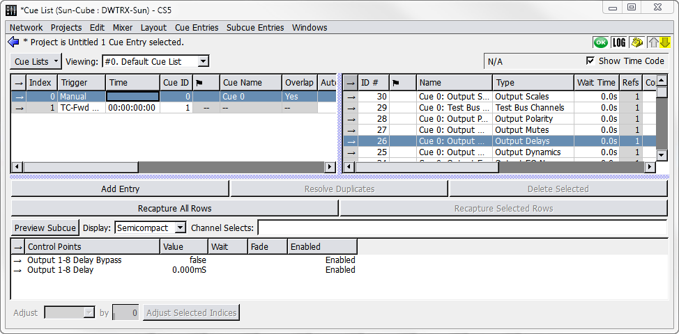 |
Cue List Window
The Cue List area of the window shows an ordered sequence of cues. These are the cues that are recalled during show control. They are always sorted according to their Index sequence. Cues can be dragged from the Cue Library to the Cue List and new Cue List entries can be created. Right-click new entries to select a cue. Note that new cues cannot be created in the Cue List window; new Cue List entries only references cues that already exist.
The columns of the Cue List pane control a range of cue automation details. When selecting a cue in the cue list, the Subcue Library pane is displayed to the right. Selecting a subcue causes the Control Point pane to be displayed beneath the other two panes.
Creating a new Cue List
When starting a new project, a Defaults cue list is created automatically, and all newly cap- tured cues are added to this list. To create another cue list, click the Cue Lists button and select New Cue List.
Additional cue lists can be used to create speaker check cue lists, different versions of a show cue list for different performers, or even cues for system testing and diagnostics.
The Cue Lists drop-down menu contains commands to select, rename, duplicate, delete, or assign new IDs to Cue Lists.
Adding Cues to a Cue List
Choose Windows > Capture. To create a new cue, check the box next to the Add New Cue To Cue List and then select a cue list. Once complete, the cue is created and added to the cue list indicated in the Capture window.
Press F3 to capture a new cue. Once complete, the cue is created. By default, using F3 does not enable Add New Cue to Cue List. If Add New Cue to Cue List is enabled manually when the Capture window is displayed, the cue is created and added to the cue list indicated in the Capture window.
Press F4 to capture a new cue. Once complete, the cue is created and added to the cue list indicated in the Capture window.
Choose Windows > Cue List and Windows > Cue Library. Drag cues with right-click from the Cue Library directly into the Cue List. A green line indicates the cue’s destination in the list. Multiple cues can be added at the same time.
Choose Windows > Cue List, and then choose Cue Entries > New Cue Entry to create an empty cue entry. Right-click in the Cue ID column to select a cue to add.
Moving Cues within a Cue List
Right-click the Cue Index number of a cue and drag it to a different position in the list. This also works when multiple cues are selected.
Cue List Timing and Automation
CueStation's cue automation allows you to set up timed sequences of cues that recall automatically, using either autofollow or timecode. This kind of automation is particularly useful when the timing of a sequence is known and unchanging (to match video playback, for instance), and can greatly reduce the need for manual cue recalling.
Timecode in Forward-Only mode
There are two options for how cues are recalled by timecode. The TC-Fwd ONLY option matches the original design of the software: only those Timecode cues after the current cue-on-deck in the Transport window are recalled by timecode. The alternative option, labeled simply Timecode, is to allow any Timecode cues in the cue list to be recalled by timecode, regardless of whether they are listed before or after the current cue-on-deck.
AutoFollow
AutoFollow is controlled by two parameters: the identity of the cue to be recalled, and the time delay before this recall happens. The automatically-recalled cue can be Next, which allows the creation of linear sequences of cues, or it can point to any cue in the list, which allows a variety of looping and branching strategies.
Right-click in the AutoFollow column for the first cue in the sequence. This cue can still be recalled manually.
Choose Next, or the index value for the cue that follows it.
Set a time in the Wait column. This is the time between the recall of the first cue and the second.
Repeat for subsequent sequential cues.
Note
To recall a sequence of cues at the same time, set an AutoFollow of 0.0 seconds for each cue in the sequence.
AutoFollow delays are cumulative because AutoFollow cues are organized in a sequential list. The time between the recall of the first cue in a sequence and the last is the sum of all the AutoFollow delays. In a sequence of five linked AutoFollow cues with 1-second delays, the final cue is recalled four seconds after the first cue.
AutoFollow techniques
AutoFollow can be used to loop a sequence of cues indefinitely by pointing the last cue in a sequence back to the first cue (or back to itself in the minimal case). This can be useful for a vamping sort of structure, where a sequence of events must repeat for an indeterminate period. It is always possible to break out of such a loop by manually recalling a cue that is not in the loop. More information about vamping in CueStation can be found in Regions, Loops, and Vamping.
AutoFollow can also be useful if you prefer to build up automation sequences in functional chunks by defining some cues as Console only, others as Matrix only, and so on. This is espe- cially true for External Command subcues, like the recall of MIDI Machine Control Locate fol- lowed by a sequence of Play commands.
Timecode
To recall a cue by timecode:
Right-click in the Trigger column of a cue, and choose either Timecode or TC-Fwd ONLY.
Enter the timecode in the Time column for the cue.
Cues recalled by timecode can be arranged into very complex and precisely timed sequences. Timecode has the advantage of much finer control over the timing of a sequence, down to a single frame. It is possible to change the timing of one cue without affecting the timing of all of the subsequent cues.
Transport window
The Transport window provides an interface for recalling cues while running a show.
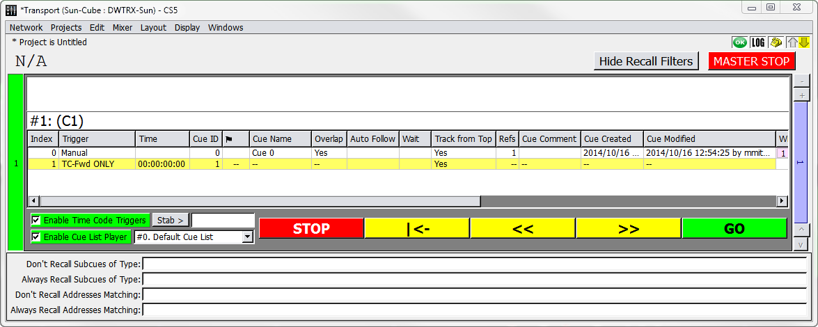 |
Transport Window
Transport window overview
The Transport window displays the Cue List Players and provides controls for recalling cues and navigating through the cue lists. The columns shown are exactly the same as those in the Cue List window, including the cue index, ID, name, and other details. The active cue and cue-on-deck for each cue list are shown at the top of each cue list player. At the top of the window is a timecode display and a Master Stop button. At the bottom of each cue list player are five control buttons, to stop, rewind, move to previous, move to next, and go.
The Stop button on each cue list player stops only automation and playback recalled by that cue list player. The Master Stop button stops all automation and playback, regardless of origin.
Tip
The Master Stop can be invoked at any time with Shift+Command+Option+M (Mac) or Shift+Ctrl+Alt+M (Windows).
Selecting a Cue List
Each cue list player has a cue list menu next to the transport controls. To create or edit cue lists, use the Cue List window, as described in “Building a Cue List” on page 98.
Navigating the Cue List
At the top of the Cue List window, the name of the active cue is displayed, along with its cue index number (reflecting its position in the cue list). Directly below it is the name of the cue-on-deck. The active cue is the cue that was most recently recalled by the Go button, timecode, auto-follow, or external control. The active cue is highlighted with a green background in the Transport window.
The cue-on-deck is the cue that is recalled when the Go button is clicked. At that point, the cue-on-deck moves to the active cue position, and the next cue in the list becomes the cue-on-deck. The cue-on-deck is highlighted with a yellow background.
The cue-on-deck can also be set by double-clicking a cue in the Transport window.
The yellow buttons at the bottom of the window change the cue-on-deck without recalling cues. Click the Rewind button to set the first cue in the cue list as the cue-on-deck. Click the Previous button to step backward by one cue button. Click the Next buttons to step forward by one cue.
Recalling cues
Open the Transport window.
Select a cue list from the Cue Lists menu. By default, the first entry in the list of cue lists is the cue-on-deck.
Click Go to recall the cue-on-deck. It becomes the active cue, and the next cue in the list becomes the new cue-on-deck.
If the cue has any wait or fade times associated with it, the Go button becomes a status bar, with the percent complete matching the countdown (in seconds) on the Go button. The count-down time is based on subcue durations, wait times, and autofollow wait times. Wild Tracks and SpaceMap Trajectory times are not included.
Recall Filtering
Subcue recalls can be filtered by type in the Transport window. Filtering provides fields for specifying subcue types to exclude from cue recalls. This provides the ability to mask the recall of parts of a subcue, while allowing the other control points or channels to be recalled. Subcue addresses can also be filtered.
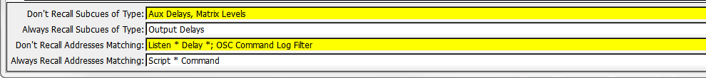
Transport Window, Recall Filtering Section
Timecode and AutoFollow
Cues recalled by timecode are recalled automatically when the timecode marker is reached. At the top of the window is a timecode display, which shows the current time and frame rate. The Enable Time Code Triggers button toggles whether timecode is online or offline.
If the Enable Time Code Triggers button is green, and the box next to it checked, timecode is enabled and D-Mitri receives timecode normally.
If the Enable Time Code Triggers button is gray, and the box next to it not checked, timecode is disabled and D-Mitri ignores any timecode it receives.
The timecode display can be hidden by deselecting Show Time Code in the Display menu. This does not affect the online/offline state.
Tip
Clear a Cue List player’s Enable Cue List Player checkbox to disable it. Dis- abled Cue Lists are indicated by a pink background and do not recall any cues.
Disabled Cue Lists ignore external triggers, timecode triggers, and autofollows.
Track-From-Top
CueStation has a Track-From-Top function similar to that used in many lighting consoles. Track-From-Top is a powerful command that quickly skips to a different point in the cue list, while setting all of the control points as though the preceding cues had all been recalled in order.
To use Track-From-Top:
In the Transport window, double-click the cue to be recalled next. The cue is highlighted in yellow and the name appears as the cue-on-deck.
Choose Mixer > Track from Top. Click Yes in the confirmation window. CueStation updates all control points as if every previous cue had been recalled in order, with a few exceptions:
Wild Tracks Deck subcues are loaded, but not played.
External subcues are not recalled unless specifically enabled (or keyed) for each subcue.
A status window shows the progress of the Track-From-Top operation, as well as the status of each DCP. When the Track-From-Top is complete, the cue that was originally selected is still the cue-on-deck, ready to be fired as needed.
Track-From-Top can be initiated from any window, but if the Cue List window is active, then Track-From-Top tracks to the cue selected in the cue list. Otherwise, Track-From-Top uses the cue-on-deck in the Transport window.
Track-From-Top: External Commands
For subcue types other than External Commands, the control point addresses act as a key so that only the last one in a sequence is used. This makes Track-From-Top more efficient: instead of recalling hundreds of input level control points at one time, only the most recent level for each channel is recalled. Commands have three different Track-From-Top settings, which are assigned default values automatically when they are created. Right-click inside the TrackFromTop column in the subcue detail section to edit the Track-From-Top settings.
Yes
The Command is set to always be recalled during Track-From-Top.
No
The Command is set to never be recalled during Track-From-Top.
Key [string]
The Command is only recalled if it is the last external with the assigned key. For example, if cues 1, 3, and 5 each have a Command that is assigned to Key: A, and cues 2 and 4 each have a Command that is assigned to Key: B, only the Commands in cues 4 and 5 are recalled.
Right-click a key and choose Reset to reset the Track-From-Top setting back to the default.
Commands saved in older projects are assigned default Track-From-Top values.
Keyboard commands
The Transport window allows for some keyboard shortcuts to select and recall cues.
Command | Function |
|---|---|
Home | Selects the first cue in the cue list (top of list). |
End | Selects the last cue in the cue list. |
Arrow keys | Select the previous or next cue in the cue list (step back and step forward). |
Enter | Recalls the Cue-on-Deck (Go). |
Cue List Players
Through the use of Cue List Players, the Transport window can have multiple active cue lists. Each Cue List Player has its own set of transport controls, and can be used to create complex sequences of automation running in parallel.
Configuring Cue List Players
The number of Cue List Players is configured in the Mixer Configuration window, just like Virtual Groups, Buses, and Bus Assigns.
At the bottom of the Mixer Configuration window, enter the number of Cue List Players to use.
Choose Configuration > Send Configuration.
Open the Transport window, and use the vertical blue scroll bar to page between Cue List Players.
Controlling Cue List Layers
Cue List Players can be captured into cues. A Cue List Player type subcue contains the value of the cue list ID, and the cue-on-deck index.
In the Cue List Player to be captured, select the appropriate cue list.
Optionally, select a cue in the cue list to be the target cue-on-deck.
Click Select on the left of the Cue List Player.
Open the Capture window using F4.
In the System Subcue Type Selection area, add a check in the box next to Cue List Player.
In the Name text box, type a name for the cue.
Click the Click to Capture New button in the lower right to capture the cue.
When the cue is recalled, the selected Cue List Player switches to the chosen cue list, with the chosen cue as the cue-on-deck.
Editing cues
In the ever-changing environment of show control, it is frequently necessary to revise cue settings. In cutting-edge design, there are times when cues will need to be built manually.
There are several different methods for editing cues. Most changes can be performed without needing to recall the cue, but sometimes it can be easier to set the mixer to the desired values and re-capture the cue with new settings.
Capture window: Capture differences
The first method of editing cues uses the Capture window and requires that changes be made live to the mixer.
Open the Mixer window and recall the cue to be edited.
Select the correct channels and make the necessary adjustments to the control points.
Use the F2 key to open the Capture window in Capture Differences mode. Make sure that the correct cue is listed in the top left drop-down box; otherwise the changes might be applied to the wrong cue.
In the Capture-Operator and Capture-Precedence boxes, assisted by the Venn (overlapping circles) diagram, choose the combination that modifies the correct set of subcue control points.
Amend Mode is the default, and is appropriate for most situations. These settings are explained in detail Capture Differences and Update Subcues.
Select the types of subcues that should be updated, or that should have subcue types added. Subcue types that are already present in the cue are underlined.
Click the Click to Capture Differences button. The subcues in the cue are updated with the new control point values.
Capture window: Update subcues
When updating a specific subcue using Update Subcues, all cues that reference that subcue are updated to use the new settings.
Tip
Use caution, as this allows easy global changes. See Working with shared subcues, for more information.
Recall a cue that contains the subcue to be updated, then adjust control points as needed.
Use the F1 key to open the Capture window in Update Subcues mode. Make sure the correct cue is listed in the top left drop-down box.
In the Capture-Operator and Capture-Precedence boxes, assisted by the Venn diagram (overlapping circles), choose the combination that modifies the correct set of subcue control points. Amend Mode is selected by default. A detailed explanation of these settings is provided in CueStation keyboard shortcuts: Capture window.
Select the types of subcues to be updated.
Click the Click to Update Subcues button. All subcues are updated but retain their original name. All cues that use this set of subcues are updated using the new settings.
Editing subcue control points
Using either of the Library windows, select the subcue that needs to be updated.
The control points associated with the subcue are shown in the lower pane. To use the cue or subcue mixer control settings as a starting-point, double-click the arrow to the right of the ID number to instantly recall the cue or subcue.
The mixer controls move to the settings specified by the subcue(s).
Set the mixer controls to the desired settings.
In the control point settings area of the window, click the Update All Rows or Update Selected Rows button as appropriate. Update All Rows update all the control points in the subcue; Update Selected Rows update only the rows that are currently selected.
Control point values in a subcue can also be edited by changing the values listed in the Value column. See the following section for more information on editing control point values.
Using the Preview Subcue feature to edit Control Points
Preview Subcue button can be used to edit control points in a subcue.
Using either of the Library windows, select a subcue to edit.
Click the Preview Subcue button at the top of the subcue editor pane. A yellow-bordered preview window appears, displaying the contents of the subcue as a mixer window.
Modify the enabled controls in the yellow-bordered preview window. This updates the sub- cue, without requiring changes to the actual audio mix.
Close the yellow-bordered preview window to finalize the changes.
Adding control points
Control points can be added or removed from a subcue. This is a particularly useful way of creating subcues that contain combinations of control points that are not easily selected through the Capture window.
Click Add Entry. A new, blank control point is added at the bottom of the list.
Type the exact name of the control point in the Control Points column. This name must correspond to an existing name in the Control Point Sets tab of the Capture window. You can add a channel range to the name. Channels are separated with a space or comma, ranges of channels are indicated by using a dash between numbers. For example, 1– 4,6,8 indicates channels 1 through 4, plus channels 6 and 8.
Using either the CueStation graphical interface, or by typing values directly, set the value, wait, and fade parameters for the control point.
To have the changes immediately take effect, double-click the arrow to the right of the ID number.
Control points can be added using the Capture window by selecting additional channels in the mixer windows and then selecting Amend Mode.
Removing control points
To remove control points, select the control point(s) and click Delete Selected.
Control points can also be removed from a subcue when using the Capture window. When a Capture Differences is performed in Replace Mode, only those channels which are selected at the time are included in the subcue. For example, if a subcue originally contains control point values for inputs 1–4, and channels 3–6 are selected for Capture Differences, the resulting subcue contains control point values for 3–6.
Copy-On-Write
A shared subcue is a subcue that is referenced by multiple cues. Updating a shared subcue in the Subcue Library window is a global change; all cues that reference it are updated to use the new control point values. However, when updating a shared subcue within the Cue Library or Cue List, Copy-On-Write is implemented. The control points for the current cue are changed, but all other cues retain the original control point values.
Copy-On-Write effects the following changes when a subcue is updated in the Cue Library:
A copy of the original subcue is created with a new ID number. All other cues are edited to reference the new subcue ID number.
The original subcue (which is then no longer shared) is changed to reflect the new control point values.
Note
If the project includes External Commands that recall subcues, the subcue ID numbers stored in an External Command subcue are changed as necessary when this process occurs.
Working with shared subcues
CueStation provides two commands in the Edit menu to assist in working with shared sub- cues.
Command | Function |
|---|---|
Individualize Subcues | This command converts all subcues to unique copies, so that no subcue is refer- enced by more than one cue. After the operation, all subcue names include the name of the cue that references it. |
Share Subcues | This operation is the converse of Individualize Subcues. When initiated, any sub- cues that have the same set of control points and values are combined into one subcue, and referencing cues are updated to reference one subcue. |
Searching cues and subcues
Search for cues and subcues by using the Find command in the Edit menu of the Cue List, Cue Library, and Subcue Library windows. A dialog box is displayed with the following controls:
A drop-down box to choose between Select Only (to clear any current selections first), Select More (to add to the current selection), or Deselect (to deselect items matching the search parameters).
A drop-down box to select the parameter type (name, ID, type, etc.).
A drop-down box to select between is or is not.
A drop-down box to select the type of matching: Equal To, Containing, Less Than, etc.
A text box to enter parameter terms, such as a subcue ID number or channel number.
A Do it button to perform the search.
Items selected by the search have their text rendered in bold, so the selection can be changed without losing the search results. To reset the text to normal, close and reopen the window.
Search and replace
Control points in cues can be batch-edited to save time. For example, with a sequence of cues that include System Level subcues, follow these steps to change the level for the entire sequence to –3 dB:
Choose Windows > Cue List, and then select all of the cues in the sequence to be changed.
Tip
Instead of selecting cues manually, use the Find command to select a particular subset of cues to change.
Choose Edit > Batch Modify Control Point Entries to open the Batch Modify dialog box.
In the first drop-down box on the left, select Set.
In the next drop-down box, select Match. In the subsequent text entry box, enter the control points that will be affected.
Enter System Level. In the last text entry box, enter the value the control points should be set to.
Enter –3. At this point, the dialog box should read: Set any control points that match System Level to –3
Click Do It to make the changes.
Examining cues and subcues
One or more cues or subcues can be examined to show their contents. Examining cues and subcues displays more specific information than shown in various columns of the Cue Library and Subcue Library windows. The Examine command is also used to compare multiple Cues and Subcues and identify their differences.
Choose Windows > Cue Library or Windows > Subcue Library.
Select a Cue or Subcue from the list.
Choose Edit > Examine. The Subcue Text View window displays the contents and information pertaining to the Cue or Subcue.
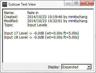
Subcue Text View Window
Choose Windows > Cue Library or Windows > Subcue Library.
Select multiple Cues or Subcues from the list.
Choose Edit > Examine. The Subcue Text View window displays the contents and information pertaining to the Cue or Subcue.
Choose Show Diffs. Text view expands to Diff view, displaying two items in separate panes. Differences are highlighted, and the number of differences is shown at the bottom of the window. The items selected in the Left and Right columns correspond to the two panes.
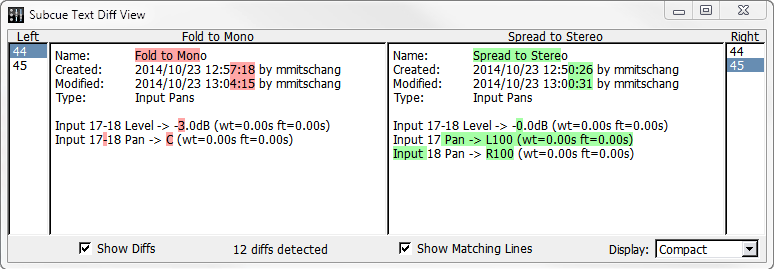
Subcue Text Diff View Window
When Show Diffs is used with more than two items, choose the item to be shown in each pane by selecting an item from the Left column and an item from the Right column. Each number corresponds to the Cue or Subcue ID.
Additional Examine commands
Additional commands are available from Diff view.
Command | Function |
|---|---|
Show Matching Lines | Displays lines that are identical between the two compared items. |
Display | Choose Expanded to parse all control point number ranges and display a verbose listing of all control points. Choose Compact to reduce the control point display by combining ranges. |
Capture Differences and Update Subcues
CueStation has unique controls for Capture Differences and Update Subcues commands. These controls will affect the capture process only if they are visible when the capture operation is executed.
Replace, Amend, Existing
These buttons provide shortcuts to the most commonly used settings. When the Capture window is opened, Amend is selected by default.
Button | Function |
|---|---|
Replace | Sets Capture-Operator to New Control Points Only, and sets Capture-Precedence to New Values Preferred. |
Amend | Sets Capture-Operator to Union, and sets Capture-Precedence to New Values Preferred. |
Existing | Sets Capture-Operator to Old Points Only, and sets Capture-Precedence to New Values Preferred. |
Operator and Precedence options
These boxes specify how the newly captured data should be combined with the data that is already present inside subcues during Capture Differences and Update Subcues operations. These controls are not relevant during Capture New operations and are therefore disabled when Capture New (F3 or F4) is selected.
There are two sets of data, shown with a Venn diagram that visually demonstrates the result of the operation:
NEW is the set specified by the Subcue Type definition, the currently-selected Channel Selects, etc. It contains control point addresses values which are to be captured from the current state of the system. The NEW set is represented in the Venn diagram by the green circle on the left.
OLD is the set of control point addresses that are already present in the pre-existing subcue. The control points of the OLD set can overlap those of the NEW. For example, the sets contain different control points if the Channel Selects differ between the sets.
The Operator setting specifies which control point addresses should end up in the resulting subcue. It has four possible states.
State | Description |
|---|---|
New Control Points Only | Discards the OLD set of control point addresses and replaces them with the control point addresses from the NEW set. This is the logic used when Advanced Mode is not active. |
Intersection | Retains only those control point addresses that are present in both the OLD and NEW sets. Control point addresses appearing in only one of the two sets will not be present in the resulting subcue. |
Union | Retains the control point addresses that exist in the OLD set and adds the control point addresses from the NEW set. |
Old Control Points Only | Replaces the existing OLD set of control point addresses with the corresponding NEW set, discarding all NEW control point addresses that were not already present in OLD set. |
The Precedence setting specifies what happens to control points that are present in both NEW and OLD sets. The Precedence setting has the following states.
State | Description |
|---|---|
New Values Preferred | Replaces the existing value with the corresponding NEW value. This is the most com- monly used setting and is the logic used when Advanced Mode is not active. |
Old Values Preferred | Retains the OLD set’s value, discarding the NEW value. This mode is useful for filling in additional control point addresses in a subcue without changing any of the subcue’s existing values. |
New Values | Always is especially interesting, because it affects not only how value-conflicts are resolved, but also which control point addresses are captured. In this mode, every specified control point address will be updated with a newly-captured value, including control point addresses that are only part of the OLD set! |
Capture Differences example
This is an example update-subcue scenario and the results from the operation with each possible combination of Operator and Precedence settings.
A pre-existing cue contains an Input Mute subcue, containing the following data:
Input 1–6 Mute = false
To demonstrate the control point status visually, channels will by listed in order with T for True and F for False. The following represents a subcue with input mutes 1–6 as false and does not contain mutes 7–8.
OLD: [FFFFFF..]
Capture Differences is used while Channel Selects specify Input Mutes 3–8 only, and all the system’s Input Mutes are active (muted) when capture takes place. The NEW set is:
Input 3–8 Mute = true
Or graphically:
NEW: [..TTTTTT]
Since there are four possible Operator states and three Precedence states, a total of twelve operations are possible.
New Control Points Only
Operator set to New Control Points Only; Precedence set to New Values Preferred.
Set | Value | Interpretation |
|---|---|---|
Old | [FFFFFF..] | Input 1–6 Mute = false |
New | [..TTTTTT] | Input 3–8 Mute = true |
Result | [..TTTTTT] | Input 3–8 Mute = true |
Operator set to New Control Points Only; Precedence set to Old Values Preferred.
Set | Value | Interpretation |
|---|---|---|
Old | [FFFFFF..] | Input 1–6 Mute = false |
New | [..TTTTTT] | Input 3–8 Mute = true |
Result | [..FFFFTT] | Input 3–8 Mute = false; Input 7–8 Mute = true |
Operator set to New Control Points Only; Precedence set to New Values Always.
Set | Value | Interpretation |
|---|---|---|
Old | [FFFFF..] | Input 1–6 Mute = false |
New | [..TTTTTT] | Input 3–8 Mute = true |
Result | [..TTTTTT] | Input 3–8 Mute = true |
Intersection
Operator set to Intersection; Precedence set to New Values Preferred.
Set | Value | Interpretation |
|---|---|---|
Old | [FFFFF..] | Input 1–6 Mute = false |
New | [..TTTTTT] | Input 3–8 Mute = true |
Result | [..TTTT..] | Input 3–6 Mute = true |
Operator set to Intersection; Precedence set to Old Values Preferred.
Set | Value | Interpretation |
|---|---|---|
Old | [FFFFF..] | Input 1–6 Mute = false |
New | [..TTTTTT] | Input 3–8 Mute = true |
Result | [..TTTT..] | Input 3–6 Mute = false |
Operator set to Intersection; Precedence set to New Values Always.
Set | Value | Interpretation |
|---|---|---|
Old | [FFFFF..] | Input 1–6 Mute = false |
New | [..TTTTTT] | Input 3–8 Mute = true |
Result | [..TTTT..] | Input 3–6 Mute = true |
Union
Operator set to Union; Precedence set to New Values Preferred.
Set | Value | Interpretation |
|---|---|---|
Old | [FFFFFF..] | Input 1–6 Mute = false |
New | [..TTTTTT] | Input 3–8 Mute = true |
Result | [..TTTT..] | Input 1–2 Mute = false; Input 3–6 Mute = true; Input 7–8 Mute = false |
Operator set to Union; Precedence set to Old Values Preferred.
Set | Value | Interpretation |
|---|---|---|
Old | [FFFFFF..] | Input 1–6 Mute = false |
New | [..TTTTTT] | Input 3–8 Mute = true |
Result | [FFFFFFTT] | Input 1–6 Mute = false; Input 7–8 Mute = true |
Operator set to Union; Precedence set to New Values Always.
Set | Value | Interpretation |
|---|---|---|
Old | [FFFFF..] | Input 1–6 Mute = false |
New | [..TTTTTT] | Input 3–8 Mute = true |
Result | [TTTTTTTT] | Input 1–8 Mute = true |
 NOTE: In this mode, control point values can be changed for channels that are not selected. For this example, we are assuming that all input channels are
muted on the mixer.
Old Control Points Only
Operator set to Old Control Points Only; Precedence set to New Values Preferred.
Set | Value | Interpretation |
|---|---|---|
Old | [FFFFFF..] | Input 1–6 Mute = false |
New | [..TTTTTT] | Input 3–8 Mute = true |
Result | [FFTTTT..] | Input 1–2 Mute = false; Input 3–6 Mute = true |
Operator set to Old Control Points Only; Precedence set to Old Values Preferred.
Set | Value | Interpretation |
|---|---|---|
Old | [FFFFFF..] | Input 1–6 Mute = false |
New | [..TTTTTT] | Input 3–8 Mute = true |
Result | [FFFFFF..] | Input 1–6 Mute = false |
Operator set to Old Control Points Only; Precedence set to New Values Always.
Set | Value | Interpretation |
|---|---|---|
Old | [FFFFFF..] | Input 1–6 Mute = false |
New | [..TTTTTT] | Input 3–8 Mute = true |
Result | [TTTTTT..] | Input 1–6 Mute = true |
Cue and Subcue Libraries
CueStation contains two windows to display libraries of all cues and subcues in a project.
Cue Library window
The Cue Library provides access to the cues that have been captured or constructed for the project. The Cue Library window has three areas: Cue Library, Subcue, and Control Point list.
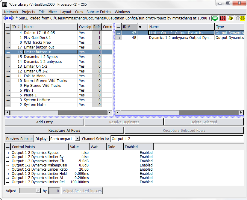
Cue Library Window
Selecting a cue shows the subcues it references, and selecting a subcue shows the control points it uses.
Note
These controls are different for Wild Tracks subcues. For more information, see Editing a Wild Tracks Subcue
Cue Library area
The Cue Library area of the window, in the upper left corner, shows the set of all cues in the project. These can be sorted by any of the column headings.
Column Data | Description |
|---|---|
ID | A unique number assigned to the cue. Show control systems recalling a cue must refer to it by its ID. |
Name | The cue name. If the cue is renamed, that change is reflected in the Cue List. |
Overlap | Indicates whether pending cue actions such as delayed subcues are completed (Yes) or canceled (No) when the cue is recalled. Yes is the default setting. |
Refs | Shows how many times the cue is referenced by a cue list. Right-click in the Refs column to see which cue lists reference the cue. |
Comment | Provides a place to type a comment. |
Created | A value indicating the date and time the cue was created. |
Modified | Shows the time and date that the subcue was last edited. |
Enabled | Shows whether a cue is enabled or disabled. Right-click to toggle between states. |
Locked | Shows whether a cue is unlocked (editable) or locked. Right-click to toggle between states. |
Wild Tracks Channel Assignments | Shows which channels are used by Wild Tracks in that cue, indicated by a green background. Right-click and drag the numbers to change the channel assignments. |
Subcue and Control Point list areas
When selecting a cue in the Cue Library window, the subcues are listed on the right, and the control points are listed in the lower pane of the window. For the most part, the subcue and control point areas of this window function like those of the “Editing Cues” on page 108, with the following exceptions:
The Update All button does not change the subcue globally. If the subcue is referenced by other cues, Copy-On-Write is used instead. More information about this process can be found in “Editing Cues” on page 108.
Update Selected works similarly to Update All, but only for the selected control points.
Building Cues
In the Cue Library window, choose Cues > New Cue. A new blank cue is shown in the appropriate list. The cue is created with the name Cue X. However, a new name can be typed immediately after the cue is created, without having to highlight it.
Choose Subcues > New Subcue Entry.
Right-click in the ID column of the subcue entry and select a subcue from the list.
Note
Subcues can be added to a cue by right-clicking and dragging them from the Subcue Library into the Cue Library and dropping them in the Subcue List area. A cue can also be created by selecting several subcues in the Subcue Library and dropping them directly into the Cue List area.
Cues menu
The Cues menu contains commands specific to the Cue Library window.
Command | Function |
|---|---|
Recall Cue | Recalls the selected cue. |
Instant Recall Subcue | Recalls the selected cue, but ignores all wait and fade times. |
New Cue | Create a new cue. |
Duplicate Cue | Duplicates the selected cue (or cues). |
Delete Cue | Deletes the selected cue (or cues). |
Subcue Entries menu
The Subcue Entries menu contains commands specific to subcues shown in the Cue Library window.
Command | Function |
|---|---|
| Recalls the selected subcue entry. |
Instant Recall Subcue Entry | Recalls the selected subcue entry, but ignores all wait and fade times. |
New Subcue Entry | Create a new subcue entry. |
Duplicate Subcue Entry | Duplicates the selected subcue entry (or entries). |
Delete Subcue Entry | Deletes the selected subcue entry (or entries). |
Capture Differences | Create a duplicate of the selected subcue, except with the current mixer val- ues. |
Update Subcues | Capture the current mixer state into the selected subcue. All other cues that reference the subcue are updated to include the updated values. |

Subcue Library window
The Subcue Library window provides access to all the subcues that have been captured or built manually for the project, and allows the creation of new subcues.
 |
Subcue Library Window
Selecting a subcue shows the control point values associated with it. Control points can be added, removed, or changed as needed.
Note
These controls are different for Wild Tracks subcues. For more information, see “Editing a Wild Tracks Subcue” on page 176.
There are two major components in the Subcue Library window: the Subcue List, to the left, and the Subcue Parameters List to the right.
Subcue List Area
This area has two control areas: a subcue type selection box on top, and a subcue list beneath.
Subcue Type selection box
The Show selection box allows you to limit the types of subcues listed. You can choose All Subcue Types, which lists all known subcues, or a specific type of subcue can be chosen.
The subcue types are maintained using the Subcue Types tab of the Capture window.
Note
If a specific type of subcue is selected, Subcues > New Subcue creates a new subcue of that same type. For example, if Mixer Settings are selected as the filter, Subcues > New Subcue creates a new Mixer Settings subcue.
Subcue List
The subcues can be sorted by any of the column headings.
Column Data | Description |
|---|---|
ID | A system-assigned number. It is user-modifiable. |
Name | The subcue name. When subcues are created by capturing, they are given the same name as that of the cue, with the subcue type appended to the name. When a subcue is renamed, any cues that reference it are updated to use the new name. |
Type | Identifies the subcue type. New subcue types can be created using the Capture window. |
Column Data | Description |
|---|---|
Refs | Shows how many times the subcue is used (referenced) by a cue, or by another subcue. Right-click in the Refs column to display a list of all of the cues (or other subcues) which reference it. |
Comment | Provides a place to type a comment. |
Created | A timestamp showing the date and time the cue was created. |
Modified | A timestamp showing the last time the cue was edited. |
Enabled | Shows whether the subcue is enabled or not. Disabled subcues are highlighted in pink, and are not recalled, even where they belong to cues that are recalled. |
Locked | Shows whether or not the subcue is locked. Locked subcues are highlighted in gray. |
Tip
If a subcue is disabled globally within the Subcue Library, it also appears as disabled within any of the cues that reference it (i.e. in the Cue Library and Cue List windows).
Subcue Parameters List area
The Subcue Parameters List area displays control points associated with any selected sub- cue. This area has two collections of controls: Command Buttons on top, and Control Point List underneath.
Tip
Subcue command types are annotated with help text, which is visible at the bottom of the Command editing area of the Subcue Library window.
Command buttons
The command buttons create, remove, update, and analyze the control points.
Command | Function |
|---|---|
Add Entry | Adds a new, blank control point to the list. When the control point is named, that name must correspond exactly to an existing name in the Control Point Sets tab of the Capture window. |
Resolve Duplicates | Enabled when one of a set of duplicated control points is selected. All dupli- cates of the selected control point are deleted, and if there are other sets of duplicate entries, only the most recently created one is saved. |
Delete Selected | Deletes a control point from the list. |
Update All Rows | Sets all of the subcue’s control points to the values of the graphical mixer controls. |
Update Selected Rows | Sets only the selected control points to the values of the graphical mixer con- trols. |
Preview Subcue | Opens a window of the selected subcue type and allows the subcue to be viewed without recalling the settings on the hardware. The window has a yel- low background. Its active controls match those that are part of the subcue, and can be used to adjust the subcue. |
Display | Determines how much detail is displayed in the Control Point List. There are three options:
|
Channel Selects | Shows which channels were selected on the latest capture. |
Adjust Selected Indices box | Shows a list of all subcue types used in that subcue, and it allows changes to the index for all types at the same time instead of having to edit each one by hand. |
To adjust an index:
Select the control points to be edited.
Choose the control point type from the Adjust Selected Indices box.
For the Adjust by value, type in the difference between the current value and the desired value. For example, if the value is 4, type 2 to change the value to 6. To reduce that 6 value back to 3, type –3.
Click the Adjust Selected Indices button to make the changes.
NOTE: In subcues with over 10,000 control points (such as a bus assign subcue affecting all input channels), the Expanded view still shows a semi-compact
view, to improve performance. To override this setting, re-select the Expanded option to view all control points individually.
Control Point List
With the exception of the Control Points column, click a column label to sort the entries alphabetically by descending order. Click the column again to sort them in reverse order. Click Control Points to toggle between different sorting methods. The first method is the traditional way of sorting by type and then by channel; all the entries of one type display first, then all the entries of the next type, and so on. The second method sorts strictly alphabetically by channel, so types alternate in the display instead of being grouped together.
Column Data | Description |
|---|---|
Control Points | Identifies a specific set of control points by name. These names correspond to those available in the Control Point Sets tab of the Capture window. A new name can be entered, but it is invalid if it does not exactly correspond to an existing name. Use the Capture window to create new control point sets. |
Value | Sets the destination value for the control point. The values can be decibels, text labels, true/ false, and so on. |
Wait | Sets the delay between recalling the subcue and the actual start of movement for the control point. This value is measured in seconds. |
Fade | Sets the length of time it takes the control point to reach its destination value. This value is measured in seconds. |
Enabled | Shows whether the control point is enabled or not. Disabled control points are also highlighted in pink, and is not recalled as part of the subcue recall. |
Caution
Duplicate control points are highlighted in red. These conflicting control point value assignments must be resolved: two identical control points can- not be played at the same time within a subcue. The only way to resolve such a conflict is to remove one of the control points.
Creating new Subcues
Choose Windows > Subcue Library to open the Subcue Library window.
Choose Subcues > New Subcue [subcue type]. Choose a subcue type appropriate for the type of control points that are to be used. A name is automatically created for the subcue depending on the type. (For some types, control points are automatically included as well.)
Add and update control points as needed.
Subcues menu
The Subcues menu contains commands specific to the Subcue Library window.
Command | Function |
|---|---|
Recall Subcue | Recalls the selected subcue. |
Instant Recall Subcue | Recalls the selected subcue, but ignores all wait and fade times. |
New Subcue > [subcue type] | Select a subcue type from the list to create a new subcue of that type. |
Duplicate Subcue | Duplicates the selected subcue (or subcues). |
Delete Subcue | Deletes the selected subcue (or subcues). |
Command subcues
Command subcues can be used to control external devices-like hard disk playback units and samplers connected to D-Mitri hardware. More often, however, command subcues are used to control various aspects of D-Mitri hardware.
Command Subcues are created from within the Subcue Library window. This differs from the method of creating mixer subcues, where the mixer is first adjusted and then captured. Avail- able commands range from simple MIDI commands to elaborate CueConsole configuration settings.
Creating a Command Subcue
Open the Subcue Library window.
Choose Subcues > New Subcue > Commands.
A new subcue appears in the subcue list in the Subcue Library window.
In the area to the right, click Add Entry.
Right-click the Type and Command entries to select from a list of available options. Type specifies the category of command, and Command selects the specific command.
Select External Control as the command type.
Type a Wait time as desired.
For most commands, parameters can be manually configured. These fields vary depending on the command that is specified. Beneath the parameter configuration area is the byte sequence that is transmitted, shown by a string of hexadecimal pairs.
Tip
String entry boxes in Command subcues support aliases in their values.
Aliases are specified with a dollar sign, followed by the alias label. CueStation expands these aliases when recalling the commands that contain them. Alias contents are specified in the Alias tab in the CueStation Mixer Configuration window (see Aliases tab for more information).
Command example
For this example, a Multi-Media Control (MMC) compatible video machine is connected to the system by an RS-232 cable. It is to be controlled through the Transport window as part of an overall audio-visual show. Specifically, to start the video at one point in the show and stop it at another point.
Create a new Command subcue and click Add Entry.
Right-click in the Type column, and select MMC.
Right-click in the Command column, and select Play.
In the left pane, name the subcue Play Video.
Repeat the above steps, but choose Stop as the command, and name the subcue Stop Video.
Either subcue can now be added to a cue. When the cue is recalled (via the Transport, time-code, CueConsole, or other means), the MMC-aware video machine starts and stops the video. If there is an option to rewind the video to the start location, a rewind subcue can also be created to use at the start of the show during initialization.
SpaceMap
SpaceMap multichannel surround panning enables the placement and movement of sound through space using a graphical interface. This chapter contains definitions of the elements that make up SpaceMap, instructions for integrating SpaceMap automation, and design guidelines on how to set up SpaceMap for various applications.
Traditional pan controls for stereo sound are one-dimensional. They shift sound along a line between two points: left and right. A SpaceMap, on the other hand, uses a two-dimensional layout (shown below), and can even be used for three-dimensional work. It can position sound anywhere on a plane, or anywhere in space.
 |
SpaceMap Window
Elements of SpaceMap
A SpaceMap design is constructed from two basic elements: nodes and Trisets. Nodes com- monly represent the positions of loudspeakers or groups of loudspeakers, and can be of sev- eral types. Trisets link three nodes together, providing the means to distribute signal proportionally among them. A Trajectory is the path along which the spatial pan control trav- els.
Nodes
Nodes are the points that audio is panned to within a map. They can represent physical loud- speakers (Speaker nodes) or simulate an output location (Virtual nodes). Nodes can also derive their audio from other nodes (Derived nodes), or discard their audio completely (Silent nodes). These types are defined in “Types of Nodes” on page 135.
Trisets
Trisets are triangular panning surfaces defined by three nodes. They ensure a smooth pan without signal drop, like a two-dimensional panning law used by a conventional pan pot. Just as two points are the minimum required to define a line, three points are the minimum required to define a plane.
CAUTION: Trisets cannot overlap one another: signal distribution would be unpredictable within the overlapped areas. An overlapping Triset turns red as a
warning.
NOTE: In circumstances where a single loudspeaker is included in a SpaceMap Triset twice—once as a Triset node, and again as a Derived Node linked to one of
the Triset nodes—CueStation now interprets the two inclusions to make the output level a sum of the two roles’ output levels.
The size of the Triset is not critical because the power-preserving panning law is proportional rather than absolute. It is based on the relative distance between the spatial pan control and each of the three surrounding nodes, rather than the actual physical distance within the grid.
Trajectories
The path along which a sound moves is called a Trajectory. A trajectory can be recorded, edited, and reshaped, then mapped to an input bus and recalled as part of a SpaceMap Tra- jectory subcue.
Trajectories can create the illusion of a moving sound, fade sounds in and out, or control a variety of other effects depending on the design of the map. The relative position of the SpaceMap bus within a Triset determines the proportion of signal sent to each of the nodes in the Triset. The actual signal levels can be seen in the Matrix window, along the row of the input bus assigned to the control.
Each trajectory is an entirely independent entity, with no absolute relationship to any one map. One map can have several different trajectories, or one trajectory for several different maps. Several trajectories can be active at once (one per bus), and there can be an arbitrary number of trajectories (and maps) in a project file.
Additionally, a trajectory can be played back with real-time modifications, such as the number of repetitions, rate, orientation, scaling, and offset in both X and Y dimensions. Several copies of the same trajectory could be assigned to different buses and performed simultaneously with different modifiers on each.
Types of nodes
There are several types of SpaceMap nodes, each serving a different function.
Trajectory Nodes
Trajectories are comprised of Trajectory nodes. Where Trisets represent loudspeaker locations and establish points from which to derive relative panning, Trajectory nodes represent the cur- rent position of a signal in each plane.
 |
Trajectory Nodes
Each TrajectoryNode contains information on both temporal and positional axes, and can have a level setting independent of the Trajectory’s level. In addition, nodes can be named and can recall text commands.
Speaker Nodes
Speaker nodes represent the physical outputs in the D-Mitri system.
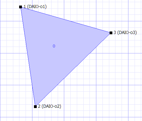 |
Triset Containing Speaker Nodes
Each speaker node is assigned to a single output. Outputs can be connected to loudspeak- ers, effects processors, or any other devices. Multiple nodes can be assigned to the same output. When a Triset contains three Speaker nodes, the audio is distributed amongst the nodes as determined by the location of the bus or trajectory within the Triset, and the relative distance between the nodes. For more information on how to create these nodes, see “Add- ing Nodes” on page 146 and “Creating Trisets” on page 147.
Virtual Nodes
A Virtual Node simulates a physical output in space by distributing its signal to the Speaker nodes to which it is linked.
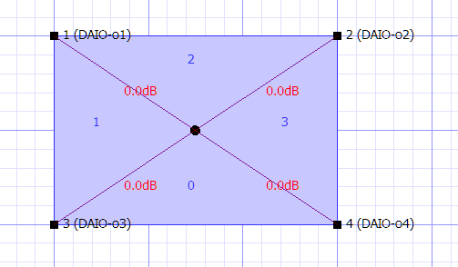 |
Virtual Node Simulating the Center of a Quadraphonic SpaceMap
By default the signal is divided equally among all the linked Speaker nodes, but proportional Link Gains can be defined that change the balance of the distribution. For more information on how to create these nodes, see “Adding Nodes” on page 146.
In this example, the Virtual Node is linked to the four Speaker nodes so that any signal that is assigned to it is equally distributed among the surrounding loudspeakers. Thus a trajectory traveling around the perimeter of the map pans linearly from one loudspeaker to the next, but a trajectory that moves toward the Virtual Node at the center of the map causes the signal to spread out to all four loudspeakers gradually. This proportional distribution method creates a convincing phantom image throughout the panning area.
Silent Nodes
A Silent Node takes part in a Triset in place of a Speaker Node but it is not associated with an output.
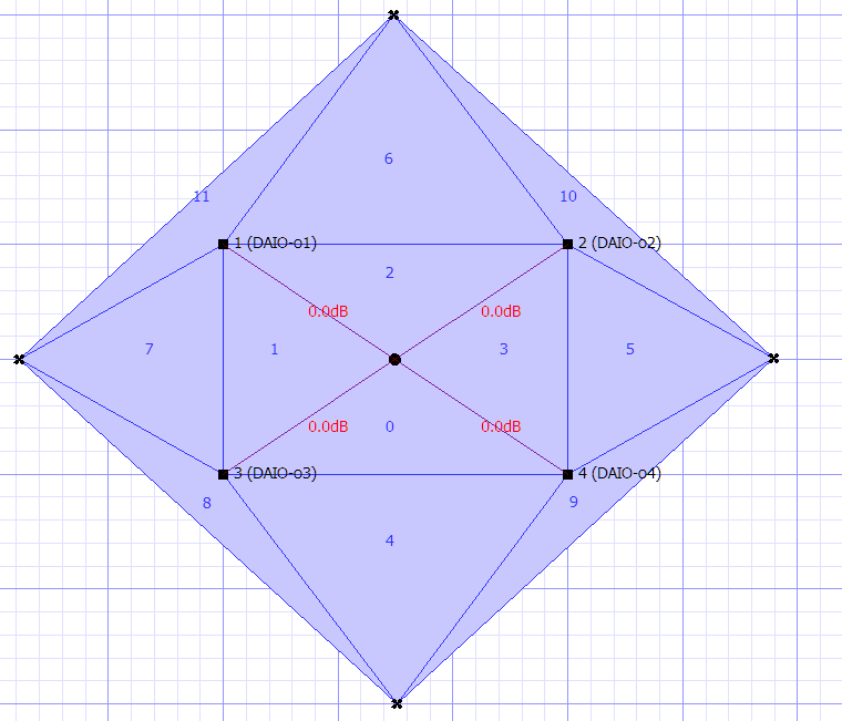 |
Silent Nodes Providing Fade Thresholds to a Quadraphonic SpaceMap
A signal panned toward a Silent Node simply disappears, providing an easy way to create fade-in and fade-out effects. This feature also solves the signal dropout problem that exists when a trajectory strays outside the panning area defined by a Triset of Speaker nodes. Since the area outside the map is currently undefined, the signal abruptly drops out. By surrounding the existing map with Silent nodes, we can create a perimeter of fadeout Trisets and guard against unintended loss of signal.
For more information on how to create these nodes, see “Adding Nodes” on page 146.
To complete our model, place four Silent nodes, one outside each side. Create Trisets, each with two Speaker and one Silent Node, or two Silent and one Speaker Node. The Speaker nodes entirely enclosed within Trisets, sound panning is now gap-free.
Derived Nodes
The Derived Node provides a way to send a signal to a secondary output whenever that signal is also being sent to a set of Speaker nodes.
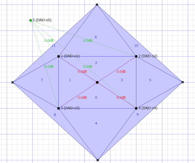 |
Derived Node Providing a Mono Sum Output in a Quadraphonic SpaceMap
Derived nodes link to one or more Speaker nodes, and receive a sum of the signals from its linked Speaker nodes. Each link between Speaker nodes and Derived nodes can be adjusted in decibels, from -89 dB to +10 dB.
Derived nodes are commonly used for subwoofer sends, fill mixes, balconies, and other cases where a secondary mix-down of a multichannel mix is required. For example, a Derived Node feeding a single subwoofer would be linked to all the main channels, so that the subwoofer receives a constant feed even if the source signal is being panned. For more information on how to create these nodes, see “Adding Nodes” on page 146.
Link Gains
By default, Virtual and Derived nodes distribute and receive, respectively, an equal proportion of the signal of their linked nodes. Link Gains allow the alteration of these proportions.
When selecting a Virtual or Derived node and its one or more linked nodes, the amount of linked gain can be changed using the Set Link Gains command (see “Setting Link Gains” on page 149).
Link Gains for Virtual and Derived nodes are expressed in decibels, with a maximum value of
+22.1 dB. Any number that is entered, down to -90 dB, is considered negative unless it is pre- ceded by a + sign.
SpaceMap Controls
In the SpaceMap window, each bus has its own SpaceMap grid view, trajectory parameters, and tools for editing both maps and trajectories.
At the top of each bus view is the matrix row, which displays exactly how much signal is going to each output.
SpaceMap Grid
Most of the SpaceMap window is devoted to a drawing area. This is where nodes are placed and linked, Trisets created, and trajectories are drawn.
 TIP: The display scaling can be decreased with Command+[ (Mac) or Ctrl+[ (Win- dows), and increased with Command+] (Mac) or Ctrl+] (Windows). The display
can be re-centered using the scroll bars.
Grid settings
There are two different grid options: Cartesian and Polar. The displayed grid type and size can be changed in the Display menu.
For cleaner-looking maps and trajectories, choose Display > Snap to Cartesian Grid or Display
> Snap to Polar Grid.
Editing tools
Directly below the SpaceMap grid view is a row of buttons for selecting different editing tools. As they appear from left to right, the buttons offer the following functions.
Button | Function |
|---|---|
Select | Select objects, Trisets, and Trajectory nodes. (Note that this is different from the Select button in the upper left corner.) |
Add Speaker Nodes | Click the grid to add Speaker nodes. |
Add Virtual Nodes | Click the grid to add Virtual nodes. |
Add Derived Nodes | Click the grid to add Derived nodes. |
Add Silent Nodes | Click the grid to add Silent nodes. |
Add Trisets | As the mouse is moved around the grid, preview lines indicate where a Triset would be placed. Click to create the Triset. Each set is numbered in order of creation. |
Test | Drag to test different locations on the grid with the active bus. This is a good way to experiment with a trajectory path. |
Trajectory Playback Controls
Below the SpaceMap grid area, there is a set of trajectory playback controls. The text box dis- playing a time in milliseconds shows the position of the bus along the trajectory, relative to time. The transport controls include the following.
Control | Function |
|---|---|
Play | Starts the bus moving along the selected trajectory's path. When playing back a trajectory, the spacebar can be used to play and pause. |
Pause | Pauses the movement of the bus. |
Stop | Stops the movement of the bus, and repositions it at the start of the trajectory. The Enter key can be used to stop a playing trajectory. |
Record | Enters record mode, for recording a trajectory. The process of recording a new trajectory is fully described in “Creating Trajectories” on page 149. |
Hold | Holds playback of the Trajectory, similar to the way the Hold button holds playback of a Wild Tracks deck in the Wild Tracks window. |
Isolate | Isolates playback of the Trajectory, similar to the way the Isolate button isolates playback of a Wild Tracks deck in the Wild Tracks window. |
Transport controls can be shown and hidden through the Display menu.
Bus Playback settings
This section of the window contains the SpaceMap automaton settings for each bus.
Setting | Definition |
|---|---|
Trajectory | Select a trajectory from the drop-down menu, or access Trajectory editing functions. |
SpaceMap A | Select a map for the trajectory to travel through, or access SpaceMap editing functions. |
SpaceMap B | Optionally select a second map, in order to pan the trajectory between two different maps. |
The following parameters are visible when Display Show Playback Details is enabled. These parameters control how a bus moves along the selected trajectory, but do not affect the actual trajectory. They are not saved with each SpaceMap or Trajectory.
Parameter | Definition |
|---|---|
Scale X | Multiplies the value of the X coordinate (horizontal). |
Scale Y | Multiplies the value of the Y coordinate (vertical). |
Offset X | Adds an offset value to the X coordinate (horizontal). |
Offset Y | Adds an offset value to the Y coordinate (vertical). |
Divergence | Controls the amount of bleed to all other SpaceMap nodes. |
Level | Controls the volume of audio signal routed to SpaceMap nodes, from +10.0 dB to -inf (silence). |
Pan | Sets the pan value between two maps. This control has no effect when SpaceMap B is set to None. |
Rate | Controls the relative speed at which the bus moves along the trajectory. |
Rotation | Rotates the trajectory path around the origin (0,0) by a relative amount. |
Repetitions | Controls how many times the bus traverses the trajectory before stopping. |
Position | Sets the starting position of the bus along the trajectory path. |
Trajectory Editor
Choose Display > Show Trajectory Editor to view the Trajectory Editor.
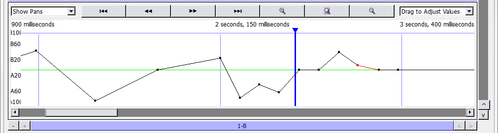 |
Trajectory Editor
The trajectory editor shows a timeline view of the currently selected trajectory. A drop-down menu in the upper left changes the Trajectory Editor display between Level, Pan, or Diver- gence of each TrajectoryNode. Across the top are buttons for scroll to start, scroll left, scroll right, scroll to end, zoom in, zoom to fit, and zoom out.
These controls affect the actual trajectory, and the parameters affect all buses that uses the trajectory.
SpaceMap Grid Settings
These settings change the appearance and behavior of the background grid through the Dis- play menu.
Setting | Effect |
|---|---|
Show Matrix Rows | Display the matrix rows at the top of the grid. |
Show SpaceMaps | Display the grid. |
Show Transport Buttons | Display the trajectory playback controls. |
Show Trajectory Editor | Display the trajectory editor at the bottom of the screen. |
Show Playback Settings | Display the bus playback settings controls. |
Show Playback Details | Display the playback details value boxes to the right of the trajectory but- tons. |
Setting | Effect |
|---|---|
Show Mouse Coordinates | Display a value box to the left of the editing tools, which shows the mouse's current position as map coordinates. |
Show All Bus Positions | Display all bus positions at once on the grid. |
Show Bus Names | Display the name of the visible bus points. |
Show Names | Display the names of all Speaker nodes. |
Show Links | Display all links. |
Show Nodes | Display all Speaker nodes. |
Show Trajectories | Display all trajectories. |
Show Node Durations | Display time between Trajectory nodes. |
Show Trisets | Display the Trisets. |
Show Images | Display any images added to the SpaceMap. |
Opaque Trisets | Display Trisets as filled with color, preventing the grid from being visible through them. |
Show Cartesian Grid | Display a Cartesian (square) grid. |
Snap to Cartesian Grid | Snap all SpaceMap objects to Cartesian grid points. |
Set Cartesian Grid Spacing | Set the spacing of Cartesian grid lines. |
Show Polar Grid | Show a polar (circular) grid. |
Snap to Polar Grid | Snap all SpaceMap objects to polar grid points. |
Set Polar Grid Spacing | Set the spacing of polar grid lines. |
Show Page Group Controls | Shows or hides the Page Group controls on the bottom of the screen. See “Page Group Controls” on page 199. |
Inserting an image
Image files can be inserted onto the grid as a reference to assist with the placement of nodes. This function can be used to place an architectural drawing or other reference image directly onto the SpaceMap grid. Supported file types are BMP, GIF, ICO, JPEG, JPG, MNG, PBM, PGM, PNG, PPM, TGA, TIF, TIFF, XBM, and XPM.
To insert an image into a SpaceMap:
Click either the SpaceMap A or SpaceMap B drop-down menu.
Choose Insert Image.
Navigate to the file location of the image and select it.
Click Open.
The image is scaled to match the SpaceMap size, and placed on the grid. To move the image, drag with the Select Objects tool.
Image control
Images can be resized by Shift+dragging. Image placement and properties can be altered after images have been inserted into a space map. To change image properties, right-click the image and select an option from the resulting menu.
Control | Function |
|---|---|
Lock Image | Merges the image with the background, removing it from the list of selectable objects. |
Unlock Image | Restores the image as a selectable object. |
Set Display Prior- ity | A numerical value which instructs the image as to which objects in the SpaceMap to visually occlude. |
Duplicate Image | Inserts an identical copy of the selected image onto the SpaceMap. |
Delete Image | Removes the selected image from the SpaceMap. |
Creating a SpaceMap
This section describes the process of creating and editing a new map. To create a blank SpaceMap:
Click the SpaceMap A button.
Select New SpaceMap,
Enter a name.
Adding Nodes
The first step in building the SpaceMap is to add Speaker nodes, Virtual nodes, Derived nodes, and/or Silent nodes.
Click Add Speaker Node.
Click anywhere in the map grid to add Speaker nodes.
Click Add Virtual Node, Add Derived Node, or Add Silent Node, then click the grid to add other types of nodes.
Speaker nodes and Derived nodes are numbered with the corresponding output channel.
Modifying Nodes
Click the Select tool.
Select the nodes to be modified. Click a single node to select it. Several nodes can be selected by holding down the Shift key while clicking nodes, or by dragging a selection box around them.
Other operations that can be performed with the Select tool include:
Drag the node(s) to a new position.
Change the node(s) types. Right-click the selected node(s), choose Set Nodes Types, and select Speaker, Virtual, Derived, or Silent.
Delete the node(s). Use the Delete key, or right-click one of the selected node(s) and choose Delete Nodes.
Link or Unlink the connection between virtual or Derived nodes and their associated Speaker nodes. Right-click the selected node(s) and choose Link Virtual/Derived Nodes or Unlink Virtual/Derived Nodes.
Change the output channel for a single node. Select a node and type the channel number of the output. Or, right-click a node, select Set Output, and choose an output channel number.
Give a single node a name. Right-click a node and choose Rename. The name is displayed beside the node.
Right-click a node (or set of nodes) to edit it with the following parameters.
Parameter | Definition |
|---|---|
Set Node Type | Select from Speaker, Virtual, Derived, or Silent. |
Set Output | Select the output number from the list, or type a number and press Enter. |
Set Aux | Select the aux number from the list, or type a number and press Enter. |
Set Node Trim | Enter a trim level for the node. |
Rename Node | Enter a new name for the node (this does not change the number in front of the name). |
Add Triset | When three nodes are selected, choose Add Triset to create a Triset connect- ing them. |
Delete Triset | Removes the Triset. |
Link Virtual/Derived Nodes | Creates links between the Virtual or Derived Node and the currently selected Speaker nodes. |
Unlink Virtual/Derived Nodes | Removes any links to the currently selected nodes. |
Set Derived Link Gains | Type in a number from +22.1 dB to -99.8 dB. |
Delete Node | Deletes the currently selected nodes. |
Creating Trisets
Add Trisets to create zones for the SpaceMap buses to move through. buses that are outside of a Triset do not produce any output signal.
Click Add Triset.
Move the pointer to the middle of any three nodes. A light green line shows the proposed Triset.
Click to create that Triset.
Alternatively, three nodes can be selected and combined. Right-click and choose Add Triset. To rename a Triset, right-click the Triset and choose Rename Triset.
CAUTION: Trisets can not overlap one another: signal distribution would be unpredictable within the overlapped areas.
Deleting Trisets
Click Add Trisets.
Click a Triset to remove it.
Alternatively, using the Select tool, right-click a Triset and choose Delete Triset. If a node that is part of a Triset is deleted, the Triset itself is deleted as well.
Testing Trisets
Set mixer control points to route audio signal to a bus.
Click the Test button.
Drag the bus through the map.
If the Speaker nodes are sending to functioning loudspeakers, the sound pans through the Trisets.
Output signal distribution changes as the bus is moved; the bus is represented as a small hol- low circle. Its label corresponds to the bus label. Level changes can be observed in the Matrix display, and at the top of the SpaceMap window.
Linking Nodes
Derived nodes and Virtual nodes must be linked to Speaker nodes in order to function.
Select the virtual or Derived Node, plus other nodes to link it to. For Virtual nodes, these are nodes that receive signal from the Virtual Node. For Derived nodes, these are nodes that send signal to the Derived Node.
Hold down the Shift key and click each node to select them.
Right-click the selected nodes and choose Link Virtual/Derived nodes. Each link is labeled with its Link Gain, a value representing the proportion of signal it sends.
Unlinking Nodes
To remove all the links for a virtual, derived, or Speaker Node, right-click the node and choose Unlink Virtual/Derived nodes.
Setting Link Gains
Link Gain behaves like a trim control, adjusting the level of the original signal that reaches Vir- tual or Derived nodes.
To change Link Gain:
Right-click a Link Gain value and choose Set Link Gain.
Enter a new value.
Click OK.
Creating Trajectories
Once a Triset layout has been created, SpaceMap Trajectories can be created and used in cues.
Creating a new Trajectory
To create a SpaceMap Trajectory:
Click the Trajectory button, and select New Trajectory.
Enter a name for the trajectory.
Click Record. The Record button blinks red.
Draw the trajectory on the grid by clicking its start position, then clicking at several discrete locations along the desired trajectory path. Paths can also be drawn by clicking and dragging.
CueStation automatically connects the dots. The time interval between dots initially corresponds to the time between clicks (see “Modifying a Trajectory” on page 150).
To stop recording, right-click in the SpaceMap grid, or move the mouse outside the SpaceMap pane.
Trajectories can be re-recorded by clicking Record again and drawing a new path. This clears the trajectory that was previously recorded.
Tip
Shift-click the Record button to pick up drawing a trajectory where it was left off. The button blinks yellow instead of red to indicate that the trajectory does not clear when recording starts.
Auto-Cue
To record a trajectory in time with Wild Tracks playback, or other types of automation, use the Auto Cue function:
Click the Record button. An Auto Cue checkbox and a Cue text box become visible to the right of the Record button.
Click the Auto Cue checkbox to enable Auto Cue.
Type a Cue ID in the Cue text box. This cue is recalled when the first trajectory point is reached.
Click the map to add a trajectory point. The cue is recalled. Continue placing trajectory points as needed.
To stop the trajectory recording, move the mouse outside the SpaceMap grid.
Tip
Cues can be set to recall along existing trajectories by right-clicking a TrajectoryNode and assigning a text command, e.g. Recall Cue 123.
Modifying a Trajectory
To edit a SpaceMap trajectory:
Select the trajectory from the drop-down menu beside the Trajectory button.
Click the Select tool.
Select points on the trajectory.
Multiple Trajectory nodes can be selected using the Shift key or by dragging a selection box around them. To select and edit multiple noncontiguous Trajectory nodes, hold Shift+Option (Mac) or Shift+Alt (Windows).
Any of the following operations can be performed on Trajectory nodes:
Drag Trajectory nodes to new positions.
To delete a TrajectoryNode, right-click it and choose Delete TrajectoryNode.
To insert Trajectory nodes, right-click a line segment and choose Insert TrajectoryNode.
To adjust duration, right-click a selected TrajectoryNode or line segment and choose Mod- ify Duration. If multiple Trajectory nodes have been selected, the change in duration is dis- tributed proportionally.
Trajectory nodes can recall commands. Right-click a TrajectoryNode and choose Set Text Command. This function can be used to recall cues and subcues once the trajectory passes over a chosen node.
To adjust the offset of an individual segment, right-click the line segment and choose Mod- ify Offset. While the offset can be changed for multiple selected segments, the result also changes the durations of the segments. An alternative to modifying offset for multiple seg- ments is changing the overall duration.
To name the TrajectoryNode, right-click the point and choose Rename TrajectoryNode.
Testing a Trajectory
SpaceMap trajectories can be tested by playing them:
Select the trajectory from the drop-down menu next to the Trajectory button.
Click Play.
To stop playback, click Stop.
 TIP: Observing the Matrix while the bus is moving (by dragging the test control or by playing a trajectory) helps identify awkward transition zones. To ensure seam-
less panning, check that the Trisets have no gaps, and consider using Silent nodes to create a smooth fade-out zone when moving to areas beyond the loudspeaker output sets. A trajectory that crosses any part of the SpaceMap window that is not inside a Triset results in a complete dropout of the signal. It is a useful practice surrounding the main part of the map with a safety zone of Trisets that includes one or two Silent nodes. This results in the sound fading as the bus moves toward the Silent nodes.
Automatic Trajectory Generation
CueStation can auto-draw a trajectory based on a parametric equation. To access this function:
Open the Commands window and add a SpaceMap type entry.
Change the Command to AutoDraw Trajectory.
Enter the values and functions to generate the X and Y coordinates, duration, pan, divergence, and level for each point. The default values create a circle.
Click Recall Selected to have the trajectory drawn automatically. This External Command can also be used in a subcue.
Creating SpaceMap Trajectory subcues
Once a trajectory has been created, trajectory playback can be added to a cue.
Channel Select the bus to assign it to the trajectory.
For that bus, select a trajectory, along with a SpaceMap A (and optionally a SpaceMap B). The SpaceMap grid reflects what you are about to capture.
Open the Capture window using F4, and type a name for the new cue. Or, open the Cap- ture window using F2, and select an already existing cue to add trajectory automation.
Under the bus/matrix category, add a check next to SpaceMap Trajectory, to include that subcue type in the new cue.
Click the Capture button in the bottom right to create the new cue. When the cue is recalled, the selected bus starts moving along the trajectory.
Tip
The current playback position along the SpaceMap trajectory is captured with the cue and saved as the Trajectory PositionPercent control point. A Trajectory PositionPercent of 0.00% sets the cue to start playback at the beginning of the trajectory.
Wild Tracks
Wild Tracks is the audio playback and recording system for D-Mitri. It uses solid-state drives to store audio files.
Wild Tracks window
The Wild Tracks window is where Wild Tracks Decks can be set up and controlled. Each Wild Tracks Unit has 32 decks.
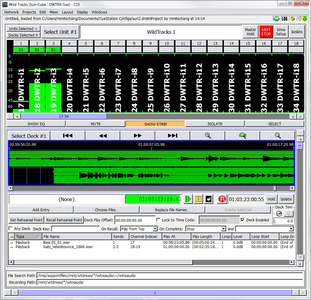 |
Wild Tracks Window
A Wild Tracks Deck is a collection of Wild Tracks entries which all share the same timeline and transport controls. Decks can be triggered individually or in groups. A Wild Tracks entry can be the playback of an audio file or tone generator, the recalling a cue or subcue, and a few other types. These are covered in “Wild Tracks Entries” on page 169. These entries can be arranged in time to create complex multitrack sequences, then captured into a Wild Tracks Deck subcue. This process is explained in “Wild Tracks Subcues” on page 173.
If you are familiar with multitrack audio editing programs, you can think of each deck as a sep- arate multitrack session, each of which can be captured into a cue and recalled inde- pendently. Each deck has a timeline, transport controls, and a list of entries (usually audio files) associated with it. Capturing a deck into a cue captures all of the information about the entries (including timing placement within the deck, volume envelopes, and loops) in addition to information about the deck as a whole (such as cursor placement or timecode locking).
Wild Tracks entries can be audio files, tone generators, or even a cue recall. Entries that have audio associated with them can be assigned to any of the Wild Tracks channels, as configured in the Mixer Configuration window. You can even assign multiple entries to the same channel.
The Wild Tracks window has four areas, each of which can be turned on or off in the Display menu. These are Meters, Deck Graphics, Deck Info, and File Search Path.
Meters
The Meters area of the Wild Tracks window displays the audio playback activity for all chan- nels, as well as global Wild Tracks controls.
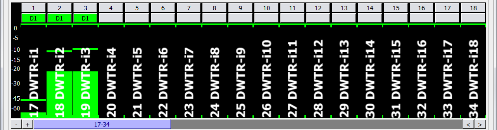 |
Wild Tracks window, Meters Area
This section includes the following controls.
Control | Function |
|---|---|
Units Selected buttons | Units Selected toggles channel select for all Wild Tracks modules. |
Decks Selected button | Decks Selected toggles channel select for all Wild Tracks Decks. |
Select Unit N | Selects the currently displayed Wild Tracks module. |
Wild Tracks Unit Label | Displays the name of the selected Wild Tracks module. |
Master Hold button | Click the Master Hold button to hold all decks of the current Wild Tracks module, effectively pausing playback from all those decks currently play- ing, and preventing the initiation of playback from those decks in the module not already playing. Click the Master Hold button again removes the hold on all decks in the current Wild Tracks module, and decks which had been playing when the hold was placed resume playback. |
Unit Stop button | Stops all the playbacks from decks in the current Wild Tracks module, without affecting other functions, such as autofollow and SpaceMaps. |
Drive Setup button | Opens the Setup Drives window (see “Setup Drives Window” on page 156). |
Isolate button | Toggles automation isolation for all decks in the current module, or, if cho- sen, for all decks in all modules. |
Channel Metering | Meters for each channel of playback. The number of channels is config- ured in the Mixer Configuration window. |
PAFL button (one per channel) | Each PAFL button is labeled with the Wild Tracks Send channel number. To use this feature, you must have at least one output configured as a PAFL. The PAFL button’s mapping follows the PAFL mapping established in the Inputs window, the checkboxes in the left column of the Inputs win- dow control these PAFL buttons the same way they control the L button in the Inputs window. It is also possible to bring up the Show Signal Path dialog by right-clicking any Send channel number. |
Deck Indicator button (one per channel) | These are below the PFL buttons. If audio is playing on a channel, the button displays the number of the deck in use. The Deck Indicator button is a shortcut to display the deck that is playing audio on that channel. |
Tablet Controls
The Wild Tracks window has additional channel editing controls, accessible through the Dis- play menu. These controls are particularly useful for tablet/touch screen displays, but can also be used with a regular mouse.
When Display > Show Tablet Controls is enabled, five buttons are displayed across the bot- tom of the window.
Control | Description |
|---|---|
Show EQ | When the Show EQ function is active, touching or clicking a meter causes the corresponding channel processing window to open, allowing quick access to EQ, dynamics, and delay con- trols. |
Mute | When the Mute function is active, touch or click a meter to mute that channel. |
Show Strip | When the Show Strips function is active, touch or click a meter to open the corresponding mixer window, with the selected channel in the first column. |
Isolate | When the Isolate function is active, touch or click a meter to isolate that channel. |
Select | When the Select function is active, touch or click a meter to select that channel. Several chan- nels can be selected at one time. |
Setup Drives Window
The Drive Setup button brings up the Setup Drives window, where you can import audio (“Importing Audio Using Drive Setup” on page 157) and create virtual drives (“Using Wild Tracks Offline” on page 183). The contents of the window depend on which tab is selected.
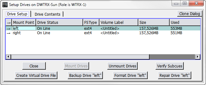 |
Setup Drives Window
The title bar of the Drive Setup window now indicates what role (if any) the Wild Tracks module is currently playing (active or backup).
Importing audio using Drive Setup
The Setup Drives dialog makes it easy to import files into the Wild Tracks window:
Click the Drive Setup button to open the Setup Drives dialog.
Click the Drive Contents tab and navigate to the folder.
Drag the audio file(s) from the local directory to the Drive Contents tab.
Drag the file(s) to the Wild Tracks window to place it in the Wild Tracks deck.
Drive Setup tab
The Drive Setup tab offers tabular data and buttons, as outlined in the following table.
Button/Column Data | Function/Definition |
|---|---|
Mount Point | Refers to the physical location of the Wild Tracks drives; left drive sled or right drive sled. |
Drive Status | Status of the Wild Tracks drive: Online or Offline. |
FSType | Displays what file system (if any) is installed on the drives. This column is populated even when the drives are not mounted. |
Volume Label | Name of the drive. This value is editable, and can be used to set the name of the drive as it should appear in the Drive Setup pane henceforward. |
Size | Total size of the drive. |
Used | Amount of space currently assigned to files. |
Available | Amount of free space. |
Comment | Enter text comments here. |
Close | Click to close the window. |
Mount Drives | Click to search for connected drives that are not listed in the Setup Drive window. |
Unmount Drives | Click to stop the drive so it can be safely disconnected (similar to ejecting a flash drive before physical removal). |
Button/Column Data | Function/Definition |
|---|---|
Verify Subcues | Click to check if the subcues are present on all locally mounted drives. |
Create Virtual Drive File | Click to create a virtual drive file. |
Backup Drive | Click to back up one selected drive to another. |
Format Drive | Click to format the selected drive. (This erases all content on the drive, a confirmation dialog is displayed.) |
Repair Drive | Click to attempt repairs to the selected drive. Drive repair is generally used to attempt recovery of a drive’s file system on those rare occasions when the file system structure has become cor- rupt. This function does not recover damaged files, but rather recovers access to files by attempting to repair a drive’s file system. |
Drive Contents tab
A row of buttons runs at the top of the tab.
Button | Function |
|---|---|
Refresh Directory | Click to refresh the window. |
Viewing: | Text box that displays the current directory's file path. |
Parent Directory | Click to go up one directory level. |
Create New Folder | Click to create a new folder in the current directory. |
Copy Selected Files | Click to copy the selected files and/or folders. |
Cut Selected Files | Click to cut the selected files and/or folders. |
Paste Selected Files | Click to paste the copied/cut files and/or folders. |
Delete Selected Files | Click to delete the selected files and/or folders. The Delete function does not move a file to the trash for possible retrieval later; the file is deleted from the drive completely. |
Upper Section
The upper section of the Drive Contents tab contains the following controls.
Checkbox/Column Data | Function/Definition |
|---|---|
Upload to both Drives | When selected, any file you upload to one drive is automatically copied to the other drive as well. |
Upload to both Modules | On a system configured with redundant Wild Tracks modules, CueStation presents an Upload to both Modules checkbox. When this checkbox is selected, CueStation directs uploaded files to both the primary and redundant Wild Tracks modules. This checkbox can be used in conjunc- tion with the Upload to both Drives checkbox to simultaneously upload to four different destination drives (two drives on each module). |
File Name | The name of the file. |
File Size | The size of the file in MB. |
Audio Length | How long the file plays in hours, minutes, seconds, frames, subframes. |
Chans | The number of channels within the audio file. |
Last Modified | The last date the file was modified. |
Lower Section:
The lower section of the Drive Contents tab contains the following controls.
Button/Column Data | Function/Definition |
|---|---|
Status | The percentage completed of a file download or upload. |
Xfer Speed | Transfer rate in megabytes per second. |
Xfer Information | What files or folders are being downloaded or uploaded. If multiple files are being downloaded or uploaded simultaneously, the information for all the file transfers appears on a single line, which is updated as the trans- actions progress. For example, for a download of six files, the information line reads 1/6 for the first of the six files, 2/6 for the second, and so on. |
Button/Column Data | Function/Definition |
|---|---|
Import Files | Imports audio files from any connected directory. |
Import Folder | Imports folders and their contents from any connected directory. |
Remove Selected File Transfers | Click to stop an exporting file in mid-transfer. File transfer is an incremental process. If stopped in the middle of a trans- fer, an incomplete file of whatever percentage had finished downloading remains on the destination drive(s). |
Deck Graphics
The deck graphic display shows the relative position of the Wild Tracks entries included in that deck.
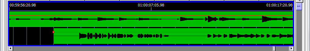 |
Wind Tracks Window, Deck Graphic Display
The controls for this area are as follows:
Controls for panning and zooming of the deck view: Scroll to Start, Scroll Left, Scroll Right, and Scroll To End.
Horizontal zoom controls: Zoom In, Zoom to Extents, and Zoom Out.
Three sets of timecode numbers, which define the span of locations currently visible within the deck view. From left to right, the numbers indicate the minimum location, the median location, and the maximum location that are visible within the window.
If there are any Wild Tracks elements enabled on the deck, they are represented by a green bar in the timeline view. Drag audio files in the timeline view to change the time when that file starts playing.
Right-click an element in the timeline to display a context menu with the following options.
Menu Item | Function |
|---|---|
Render Track Waveform ([length]) | This allows you to view the waveform of the track you are using, similar to many multitrack editing programs. In order to preserve processing power, only the portions of the files that are currently visible within the deck are rendered. |
Render All Track Waveforms ([length]) | Selecting this will cause all waveforms in the deck to be rendered. |
Cancel Waveform Rendering | Stops rendering the selected file. |
Cancel All Waveform Rendering | Stops all rendering. |
Clear Waveform Image | Clears the waveform rendered on the selected track. |
Clear All Waveform Images | Clears the waveforms rendered on all tracks. |
Clip Initial Silence | Adjusts the Wild Tracks Entry to eliminate silence at the beginning of the track. Choose the threshold (dB) for determining where silence ends and audio content begins. (The file itself is not changed.) |
Seek to Beginning of Track | Click to go to the beginning of the track. |
Seek to End of Track | Click to go to the end of the track. |
Clear Selected Track Region | Click to remove a selected portion of the track. |
Select Entire Track as Track Region | Selects the entire track. |
Select Intro Region as Track Region | Selects only the intro region of the track (from the left edge of the green bar to left edge of the first loop). |
Select Loop Region as Track Region | Selects only the loops region of the track. |
Select Outro Region as Track Region | Selects only the outro region of the track (from the right edge of the last loop to the right edge of the green bar). |
Clear Track Loop Region | Click to clear any looping designations on a track. |
Menu Item | Function |
|---|---|
Clip Track to Selection | This option is only available if a region is selected, and it will set the File Offset, Play Offset, and Play Length values to correspond with that region of the file. |
Unclip Track | Click to reset File Offset, Play Offset, and Play Length values back to their defaults. |
Make Batch File from Track | This will make a batch file of the track you have selected, which can then be used in other subcues. |
 TIP: Use Command+[arrow keys] (Mac) or Ctrl+[arrow keys] (Windows) when a file is selected in the timeline to snap it to the nearest edge of another file, the top
of the deck, or the cursor.
Changing the Height of Tracks in Timeline
The deck timeline can be zoomed vertically as well as horizontally. Use the following Display menu commands to change the vertical zoom.
Command | Function |
|---|---|
Make Bars Shorter | Zoom out vertically. |
Make Bars Taller | Zoom in vertically. |
Reset to Default Bar Height | Reset to the default zoom level. |
Wild Tracks Envelopes
In the Wild Tracks window, you can draw volume envelopes in the Deck timeline, and capture them as part of the Wild Tracks Deck subcue. This allows greater control over level adjustments between tracks and reduces the number of additional cues required to make level changes.
Right-click a track in the timeline to access the following options.
Option | Function |
|---|---|
Adjust Envelope Levels in Selected Range | This will adjust all selected points by the same amount. This is only enabled when a region of the entry is selected. |
Convert Envelope to 'Simple/ Loop-Aware' Envelope Type | There are two types of envelope types: Simple and Loop-Aware. Loop- Aware envelope points will repeat with looped regions, whereas Simple ones will not. |
Clear Envelope Points in Selected Range | Clears all of the envelope points in the selection. |
Display File Format Information | Displays the file format type (WAV, AIFF, etc.). |
Tip
When editing envelope points in the Wild Tracks window, you can hold Shift when dragging to only affect the time (horizontal movement). Hold Option (Mac) or Alt (Windows) to only affect the level (vertical movement). Hold Command (Mac) or Ctrl (Windows) for fine control of point movement when zoomed out.
Deck Info
The Deck Info area consists of two sections: Deck Controls and Wild Tracks Elements.
Deck Controls
The Deck Controls section has options and controls that relate to the entire deck.
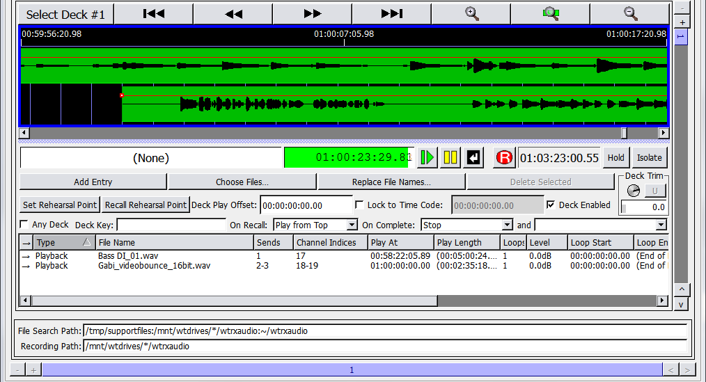 |
Wild Tracks Window, Deck Controls
The following table contains a list of deck controls accessible from the Wild Tracks window.
Option/Control | Function |
|---|---|
Deck ID number | Click to select a deck for capturing subcue information. |
Deck Label | Displays the ID number of the subcue recalled for that deck, the name of the file assigned to that deck, and the Wild Tracks and Deck ID numbers. |
Deck Playback Position | Shows the current cursor position within the timeline of that deck. |
Transport buttons | Play, Pause, Stop, and Record. |
Option/Control | Function |
|---|---|
Total Play Length | Shows total play length. |
Hold button | Acts similar to a pause button, but does not affect the playing/stopped status of the deck. |
Isolate button | When the Isolate button is active (yellow), the deck will not be affected by cue automation. |
Add Entry | Allows you to add a Wild Tracks element to the deck. This can include a file for playback, a tone or noise generator, or a few other types; see “Wild Tracks Entries” on page 169. |
Choose Files | Opens a dialog box to add audio files to the deck. You can also add files by dragging them into the Deck Info area from a directory listing. |
Replace File Names | Allows you to switch out the selected file for a different one. |
Delete Selected | Removes the selected element from the list. |
Set/Recall Rehearsal Point but- tons | These allow you to place or go to rehearsal points in the deck, which means you can start a Wild Track at any point in its playback sequence. For more information on setting and recalling rehearsal points, see “Set/ Recall Rehearsal Points” on page 168. |
Deck Play Offset | Indicates the point on the deck timeline where playback will start. The default is the beginning of the deck. |
Lock to Timecode checkbox | Locks the deck transport to external timecode. |
Timecode field | Used to lock the deck playback to timecode. Playback will stop when the Timecode stops, or the deck reaches the end of the playback range. |
Deck Enabled | Normally selected, activating the subcue. When this box is unchecked, the subcue will not play back when recalled. If you are programming a sequence of overlapping Wild Tracks Deck cues, this allows you to listen to only the subcues you are working on. |
Any Deck checkbox | If checked, signifies that the Wild Tracks subcue does not explicitly spec- ify which deck should be used for that subcue. In this case, when the subcue is recalled, CueStation assigns it to a deck that is currently not in use, starting with the highest number available. If Any Deck is NOT checked, then every time the subcue is recalled, it will use the same deck. |
Deck Key text box | To set a key for the deck. More information about using deck keys can be found in “Advanced Techniques” on page 181. |
Option/Control | Function |
|---|---|
On Recall drop-down menu | To select which state the deck should be in when recalled by a subcue. |
On Complete drop-down menu | To select the desired action when the deck cursor reaches the end of the last entry in the timeline. |
Action text box (beside On Complete drop-down menu) | Provides the option of assigning any valid text command, as described in Appendix C, “D-Mitri Text Commands.” |
TIP: When using multiple decks, it can be difficult to keep track of which decks are playing. To create a compact Wild Tracks display, choose Windows > Clone
Window command, and turn off all display options. This creates a second Wild Tracks window that displays only the deck label, deck playback position, and transport but- tons.
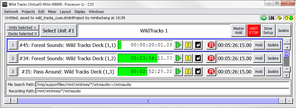 |
Compact Wild Tracks Display
Wild Tracks Elements
The next area within the Deck Info section is a list of all the elements included within the Wild Tracks Deck subcue.
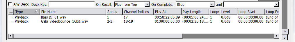 |
Wild Tracks Window, Elements Section
Click a column heading to sort the elements alphabetically by the contents of that column. Click it again to sort them in reverse order.
Element | Function |
|---|---|
Type | Shows the type of element, and also determines what kind of information is listed in the File Name column. Right-click in the Type column to change the type of element. See “Wild Tracks Entries” on page 169 for a full description of these types. |
File Name | Identifies the name of the file, if the entry is a Playback type. If it is a Record entry, File Name indicates the name of the file that will be written to. |
Sends | Specifies a list of Wild Tracks sends to which the audio should be routed. |
Loops | Allows you to replay the file or file region repeatedly. Set this value to -1 to loop indefinitely. |
Level | Specifies the volume level (in dB) of the file or tone generator. |
Play Length (hh:mm:ss:fr:sf) | Specifies the duration of playback. Note that this can be set to a value shorter than the actual length of the file to play back a region of the file. |
Loop Start | Sets the start time of the region to be looped. The default is the start of the file, but you can create smaller regions within the file to be looped. |
Loop End | Sets the end time of the region to be looped. |
Cross Fade | Sets the amount of cross fading you want Wild Tracks to use for loop-iter- ation discontinuities. The default cross fade time is 30ms. For no cross fade, set it to 0ms. There is no maximum cross fade time, although values greater than half of a loop iteration will be treated as if they were equal to half of a loop iteration. |
Element | Function |
|---|---|
File Offset | Specifies the point within the file where playback should begin. This, combined with Play Length, allows you to play back a region of the file. |
Play At (hh:mm:ss:fr:sf) | Specifies the point in the deck timeline where the file will start playing. |
File Format | Displays the format of the file, for recording entries. |
ID | Sets a unique ID for the file entry. |
Enabled | Displays whether the track is enabled or disabled. |
Paths
The File Search Path is the default directory that Wild Tracks searches for audio files on the Wild Tracks drives. Recording path is the default directory where Wild Tracks will record audio.
 |
Wild Tracks Window, Paths Section
Set/Recall Rehearsal Points
The Set Rehearsal Point and Recall Rehearsal Point buttons allow you to place or go to rehearsal points in the deck timeline.
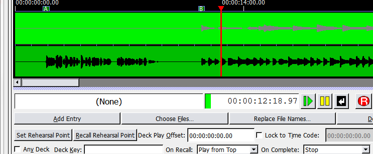

 Points Rehearsal
Set and Recall Rehearsal Point buttons
Wild Tracks Window, Rehearsal Point Controls
To set and recall rehearsal points:
In the Wild Tracks deck, move the red time indicator bar to the desired spot.
Click the Set Rehearsal Point button. A rehearsal point selection dialog is displayed.
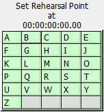 |
Rehearsal Point Selection Dialog
Select the letter you want to associate with the rehearsal point.
The rehearsal point will be placed at that point in the Wild Tracks deck. To start the cue at a rehearsal point, click Recall Rehearsal Point and select the point's letter from the context win- dow.
Wild Tracks entries
This section describes the different types of Wild Tracks deck entries and the parameters associated with them.
Entry Parameter | Definition |
|---|---|
Playback | The Playback type has an audio file associated with it, which will be played according to the offset and loop values. The file will be listed in the File Name column. |
Record | Indicates that when the subcue is recalled, recording will begin on that deck, on the channel(s) listed in the Sends column. |
Sine Wave | Generates a sine wave for an infinite length of time. The default frequency is 261.63 Hz (middle C), but you can specify any frequency between 1Hz– 24kHz by typing the number into the File Name column. |
Pink Noise | Generates an infinite amount of pink noise. |
White Noise | Generates an infinite amount of white noise. |
Entry Parameter | Definition |
|---|---|
Frequency Sweep | Generates a series of tones that sweep a range of frequencies. The default is a five second sweep that rises from 20Hz to 20kHz. To adjust the length of the sweep, enter a different value into the Play Length col- umn. To adjust the starting frequency, type the value into the File Name column. For example, type pitch=500 to start at 500Hz. To specify both starting and ending frequencies, specify the pitch twice. For example, type in pitch=500 pitch=100 to specify a sweep that starts at 500Hz and sweeps down to 100Hz. |
Square Wave | Generates a square wave of infinite length. The frequency and duty cycle can be specified in the File Name column. For example, enter 440 duty=50 in the File Name column to generate a wave at 440Hz with a duty cycle of 50%. |
Triangle Wave | Generates a triangle wave. The frequency and duty cycle can be specified in the File Name column. For example, enter 440 duty=50 in the File Name column to generate a wave at 440Hz with a duty cycle of 50%. |
Sawtooth Wave | This generates a sawtooth wave. The frequency and duty cycle can be specified in the File Name column. For example, enter 440 duty=50 in the File Name column to generate a wave at 440Hz with a duty cycle of 50%. |
Command | Executes the specified text command. Right-click the File Name field of a Command entry to reveal examples of commands that can be executed. The commands include Recall Cue, Recall Subcue, Update Cue, Update Subcue, Print Message to Log, and others. You can create a Recall Cue or Recall Subcue entry by right-clicking a cue or subcue and dragging it into a Wild Tracks deck or Wild Tracks deck subcue. |
Rehearsal Point | Sets a rehearsal point in the timeline view. |
Command Cue Context Menu
For cues with the Command Type, right-clicking in the File Name area activates a new context menu containing descriptions of commonly used D-Mitri Text Commands. You can leave the command as-is or edit it to suit the parameters.
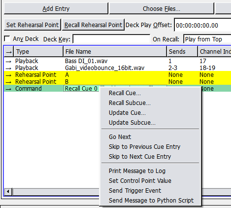 |
Command Cue Context Menu
Example: after selecting Go Next from the context menu, the text Go on Player 1 appears in the cell. This command presses the GO button in the Transport Window for Cue List Player #1 when the command track is played.
Note
Any valid D-Mitri text command can be entered into the File Name field.
The context menu only provides examples of commands that are likely to be useful when being executed from a Wild Tracks deck. For more information on D-Mitri text commands, see Appendix C, “D-Mitri Text Commands.”
Text Command | Function |
|---|---|
Recall Cue | Brings up the Select a Cue dialog with a list of current cues, along with their ID numbers and names. |
Recall Subcue | Brings up the Select a Cue dialog with a list of current subcues, along with their ID numbers and names. |
Update Cue | Brings up the Select a Cue dialog with a list of current cues, along with their ID numbers and names. |
Update Subcue | Brings up the Select a Cue dialog with a list of current subcues, along with their ID numbers and names. |
Go Next | Equivalent to pressing a GO button in the Transport window. If on player N is specified, then the GO button will be pressed on Cue List Player #N. If not, it will default to Cue List Player #1. |
Skip to Previous Cue Entry | Skips to the previous cue position in the Transport window. |
Skip to Next Cue Entry | Skips to the upcoming cue position in the Transport window. |
Print Message to Log | Prints the specified text to the system log. |
Set Control Point Value | Sets the specified values to the specified addresses. The syntax is similar to what is seen in Mixer Parameter subcues. For example, set input 1–8 level = +5.5 or set output 5,7,9–11 mute = false. The following example specifies a wait of 5.5 seconds followed by a fade over 10 seconds: set input 1 level = –50.0 waitTime=5.5 fadeTime=10.0 |
Sent Trigger Event | Sends a Trigger Event to the D-Mitri system. Any triggers (previously set up with the External Control/Setup Triggers command) that match event string will be activated. |
Sent Message to Python Script | Launches a new Python script process in the specified slot in the Script Execution window. A slotindex value of –1 will cause the script to be run in the background (not shown in the Script Execution window). The filename should be the name of a python script in the Support Files window, or in the templates folder. |
Also, for cues with the Command Type, the file name of any cue or subcue now includes its reference name (such as Recall Cue 0).
Select a Cue Window
To assign a cue to a Command entry, right-click the File Name field to display the available command types. The Select a Cue window is displayed when choosing Recall Cue, Recall Subcue, Update Cue, or Update Subcue. The Select a Cue window contains a list of current cues or subcues, along with their ID numbers and names.
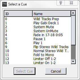 |
Select a Cue Window
When a cue or subcue is selected, the effect depends on whether you previously selected Recall or Update.
Command | Function |
|---|---|
Recall Cue/Subcue | Selected cues or subcues will recall when triggered. |
Update Cue/Subcue | Allows modification of the selected cue or subcue so that its control points match the values of those control points currently set in CueSta- tion. |
Wild Tracks subcues
Wild Tracks Deck subcues contain a variety of information about playback (or recording) of audio files. Each subcue corresponds to a single Wild Tracks Deck, which can contain up to 24 tracks of audio playback. You can specify the deck number explicitly, or set it to Any Deck to let CueStation choose a deck automatically.
There are two main methods of creating a Wild Tracks subcue. The easiest and fastest method is by dragging audio files into the Cue List window. Another method is to set up a multitrack sequence within the Wild Tracks window.
Creating a Wild Tracks Subcue in the Cue List Window
This is the quickest way to create Wild Tracks subcues.
Open the Cue List (or Cue Library) window.
In the operating system, open a file browser window and navigate to the wtrxaudio
directory.
Click an audio file and drag it directly into the list of cues section of the Cue List window.
CueStation will automatically create a cue that contains one Wild Tracks deck subcue with the following information:
The subcue will be a playback type Wild Tracks deck subcue, with the file offset, play off- set, level, loop count, and playback position set to defaults.
CueStation will automatically detect how many tracks are in the audio file and assign it the appropriate number of sends.
In the subcue, the Name field will be set to an asterisk (*), which signifies Any Deck. When the cue is recalled, CueStation will automatically assign it to the first available deck, start- ing with the highest number. For instance, if you have 32 decks, the cue will be assigned to deck 32, unless that deck is already in use, in which case it will be assigned to deck 31.
At this point, you can edit the subcue directly within the Cue List window. If you want to change the deck number, for instance, that can only be done by editing the Name field in the subcue.
Or, if you recall the cue, you can then set the input levels, pans, and other settings appropri- ately, and then use Capture Differences to add these control points into the same cue.
When the subcue is recalled, the Deck Label in the Wild Tracks window is automatically set to the name of the subcue, as shown.
Creating a Wild Tracks Subcue in the Wild Tracks Window
This method of creating a Wild Tracks deck subcue is useful for creating more complex multi-track sequences.
Open the Wild Tracks window and locate a deck that is not in use.
Drag in audio files; playback entries will be created for them automatically. Alternatively, you can click Choose Files to add audio files. The sends are assigned automatically for each file, but can be changed by clicking in the Sends column and typing in new channel numbers. Multiple Wild Tracks files can be assigned to the same channels.
Tip
Drop a file directly onto a meter to automatically assign the file to that channel.
As files are added, they appear in the timeline view as green bars. Drag the green bars to move them forwards or backwards in time within the deck.
You can fine-tune the timing by editing the Play Offset value for each file. This value determines the point in the deck's timeline where the file will start playing. Level is set to 0 dB by default; this can also be edited to balance out the mix within that deck. Additionally, different levels can be assigned for each track in the audio file, separating the values with commas (for instance: –10,–5). If volume envelopes are added, this value will be replaced with envelope values.
To loop part or all of a file, set the Loops value to the number of times the file should be looped, or type –1 for infinite looping. See “Regions, Loops, and Vamping” on page 180 for more information.
After adding files and arranging them in the deck timeline, Click the Select Deck button.
Press the F4 key to open the Capture window. The selected deck is listed in the Channel Selects area.
If the deck is the only thing you are capturing into the cue, make sure that all other sub- cues types are unchecked, then click the checkbox next to Wild Tracks Deck.
Click to Capture New to capture the cue.
Editing a Wild Tracks Subcue
Wild Tracks parameters captured by CueStation can be directly edited in the subcue window.
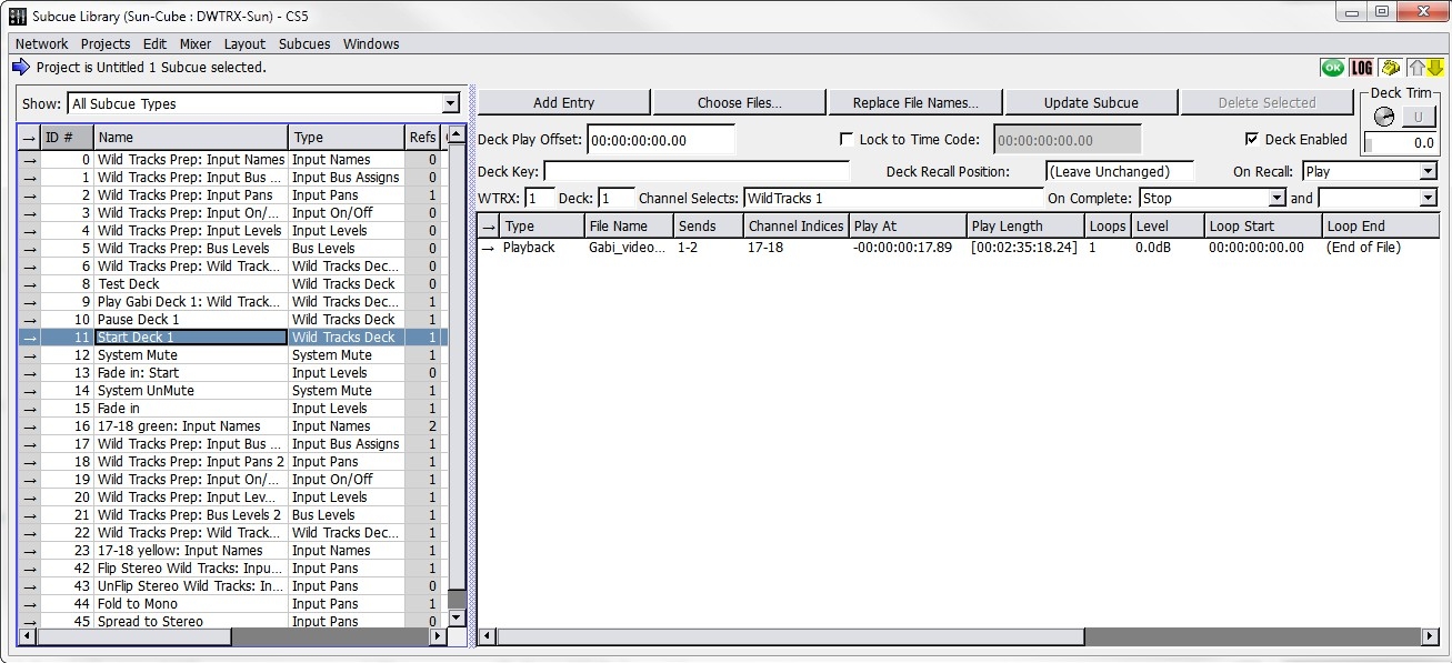 |
Subcue Library Window, Details for a Wild Tracks Subcue Displayed
Wild Tracks subcues can also be created entirely within the Subcue Library. Use Subcues > New Subcue > Wild Tracks Deck to create a new subcue. Controls are similar to those described in “Wild Tracks Window” on page 153, with several additional options. The following values constrain the operation of the entire deck.
Parameter | Function |
|---|---|
Deck Enabled | Normally selected, activating the deck. When not selected, the deck will not respond to automation. This allows you to easily skip specific sub- cues while designing the list. |
Deck Recall Position (hh:mm:ss:fr:sf) | Specifies the point along the deck timeline at which the deck cursor will begin playback. |
On Recall | Selects one of the following values: |
Continue | This will load in the new deck info, without affecting the playback status of the deck. If the deck was paused before the subcue was recalled, then it will remain paused. |
Stop | This stops the deck when the subcue is recalled. |
Parameter | Function |
|---|---|
Play | This loads the start of the file into the playback buffer, and then starts playing audio. |
Play from Top | This works similarly to Play, except that the Deck Recall Position is ignored and playback always starts from the beginning of the deck. |
Record | This lets you record audio from an input channel to a file on the Wild Tracks drive. |
WTRX | Specifies the Wild Tracks module used by the subcue. |
Deck | Specifies the Wild Tracks deck within that module. Enter an asterisk (*) to signify Any Deck. |
On Complete | Stop (default): When the cursor reaches the end of the last entry in the timeline, playback stops and the cursor returns to the beginning of the deck. |
Pause: The deck will pause after the last entry, with the cursor remaining in place. | |
Reset Deck: Removes all entries and resets deck parameters to default values. | |
Clear Deck: Removes all entries. | |
Disable Deck: Disables the deck. | |
Continue: The deck continues playing past the end of the last entry. | |
Continue from Top: The deck starts playing at the beginning of the deck. |
Assigning Multitrack Files to Sends
Track assignments are made in the order listed in the Sends column. The first track of a multi-track file is mapped to the first send listed, the second track to the second send listed, and so on.
For example you could specify 8,1,6,2–4, so that the file's first track will play on channel 8, the second on channel 1, the third track on channel 6, the fourth on channel 2, the fifth on channel 3, and the sixth track on channel 4.
Descending ranges are also permitted. For example, a multi-track audio file can be mapped to sends 16–1. The first track of the audio file is routed to the 16th channel, the second track is routed to the 15th channel, and so on.
Playing individual tracks
You can extract tracks out of a multi-track file by making a null assignment of the unwanted tracks. If 0 (zero) is used as a send value, the track will not be played.
For example, to play only the right-hand stream of a stereo file, specify the send as 0,1.
To send only the right channel of a stereo file to several different input channels, you could specify 0,1,0,2,0,3. For the left channel only, it would be 1,0,2,0,3,0.
To do the normal round-robin assignment mapping with the right channel only, prepend a zero to the sends. For example, 0,1–16 would cause channel 1 to play the right-hand stream, chan- nel 2 to play the left-hand stream, channel 3 the right-hand stream, and so on.
Recalling Wild Tracks subcues
When traversing through a cue list, CueStation will look ahead and preload Wild Tracks deck subcues into a buffer. When the cue is recalled, the playback of audio files will begin as soon as the subcue is recalled.
Optimizing Wild Tracks
This section describes how to get the best performance for Wild Tracks playback.
File type and format
Wild Tracks supports many different formats of audio files (see “Supported Audio File Types” on page 216 for a complete list). All files must have a 96kHz sample rate.
Deck Recall Time
For a Wild Tracks deck subcue, the length time between when the subcue is recalled and when the deck starts playing can be longer than desired, especially if there are many audio files to be loaded. Therefore, it can be very beneficial to load the deck (without playback) at a time before playback is required.
When recalling cues in a cue list, CueStation will look ahead at the next cue and automatically preload Wild Tracks deck subcues. These subcues will not be visible in the Wild Tracks window; they are loaded in the background. This can reduce time-until-playback by up to 98%.
It is possible also to manually control when decks are loaded, rather than relying on the preloader algorithm to perform preloading. This technique is useful in circumstances such as when a loaded deck is going to be played by means of a remote cue recall. To manually control deck loading, you will need two cues per Wild Tracks playback: one cue to load the deck, and another cue to start playback.
Create a Wild Tracks deck subcue as you normally would, then change the On Recall action from Play from Top to Stop. This will prevent the deck from playing after it is loaded.
Take note of which deck the subcue will use.
Add this subcue to a cue in the cue list, and position it before the cue where you want to recall playback.
Arrange the CueStation windows so both the Wild Tracks and the Cue List windows are visible, and select the cue where you would like to trigger playback.
Right-click and drag the Play button in the Wild Tracks window into the list of subcues of the cue that is selected in the Cue List window. This creates a new Mixer Settings subcue, which has the following information:
Wild Tracks unit number
Deck number
Status Play.
At this point, the cue list will have a sequence of two cues to initiate Wild Tracks playback. The first cue loads the files into a deck, and the second cue triggers playback. This can significantly reduce the trigger time when recalling the second cue. If the second cue is recalled without first recalling the loading cue, playback will not work as desired. For instance, if there are other files loaded into that deck, then those files will be played instead of the ones you were expecting.
Note
Decks can also be controlled by key to control the playback of a pre- loaded deck. For more information, see “Control Decks by Key” on page 182
Caution
It is possible to trigger multiple decks on one Wild Tracks Unit, such that more than 216 tracks are playing simultaneously. In this situation, audio dropouts are highly likely to occur, and warning messages will be printed to the log. When attempting to play more than 250 tracks, the most recently triggered deck(s) will automatically Hold until manually reset.
Regions, Loops, and Vamping
In Wild Tracks, you can create regions within an audio file. These regions allow you to loop a section of a file infinitely or a certain number of times. You can also change the number of remaining loops while the deck is playing to create a vamp-until-triggered effect.
Command-drag (Mac) or Ctrl-drag (Windows) in a green bar in the Wild Tracks timeline to specify a section of the playback region. The specified section will be highlighted in blue. Once the selection is made, Command-click and drag (Mac) or Ctrl-click and drag (Windows) either end of the blue selection bar to adjust the area it covers. Right-click the green bar and choose Select Entire Track as Track Region to make the blue selection area match the entire length of the audio track.
Loops
Wild Tracks can loop an entire file, or a region within a file. To loop an entire file:
Enter a number for the Loops value:
To loop the file a set number of times, enter a whole number greater than zero.
To loop the file infinitely, enter –1.
To create a loop for a region within a file:
Create a region by control-dragging the mouse over the part of the file. The region is high- lighted in blue.
Right-click the region and choose Set Track Loop Region. This command will change the Loop Start and Loop End times for the selected file to match the selected region. These values can be edited manually to fine-tune the timing of the regions.
Enter a number for the Loops value:
To loop the region a set number of times, enter a whole number greater than zero.
To loop the region infinitely, enter –1.
Vamping
Vamping is used to loop a region of an audio file continuously until it is triggered to continue, at which point it will finish playing the current region and then continue on to the next region.
To accomplish this in Wild Tracks, use the following procedure:
Create a region as described in the previous section.
Set Loops to infinite by typing –1 or inf in the Loops column.
Capture the deck into a cue called Start Vamp. This will be the setup cue that starts the vamping sequence. Note the deck number and the ID for the looping playback entry.
Open the Subcue Library and create a new Commands subcue with a Type of Wild Tracks and a Command of Set Loop Counter.
For Target Deck:, enter the number of the deck used in the Wild Tracks subcue.
For Target Track:, enter the ID number of the Wild Tracks playback entry.
Create a new cue that includes the External Commands subcue, and name it End Vamp.
Add both cues to the Cue List.
The Start Vamp cue will begin Wild Tracks playback, and loop indefinitely until End Vamp is recalled.
Note
If the End Vamp cue is recalled less than two seconds before the end of the region, an extra loop will be played. This is because part of the next loop has already been loaded into the Wild Tracks audio buffer. If the looped region is less than two seconds, it could result in several extra loops after the loop counter is reset.
Advanced techniques
This section lists some advanced techniques for using or controlling Wild Tracks.
Mixer Settings subcues
Mixer Settings subcues can be used to control transport actions on a deck or set of decks. Mixer Settings subcues can be created for any control point in CueStation by right-clicking the control and dragging it into the cue or subcue library. For example:
Open the Wild Tracks window and the Cue Library window, arrange them so both are visi- ble.
In the Wild Tracks window, in Deck 1, right-click and drag the Stop button into the Cue Library.
A new cue will be created, containing a Mixer Settings subcue.
If you click the subcue, you will see Wild Tracks 1 Deck 1 Status in the Control Points col- umn. You can change the value of the deck. For example, you might enter a value of Deck 1–5 to stop a range of decks at the same time.
In the Value column, you will see the word Stop. This can be changed to Play, Pause, etc. The Wait and Fade times are not valid for this type of control point, and the Enabled col- umn shows whether or not the control point(s) are enabled.
Control Decks by Key
Mixer Settings subcues can only control decks if you know which decks will be in use. For subcues assigned to Any Deck, the deck number depends on which other decks are in use. However, it is still possible to automate control of these decks, using deck keys. There is a Wild Tracks external subcue, Control Decks by Key, which allows you to control a set of Wild Tracks Decks that share the same pre-assigned key. To use this feature:
Create a Wild Tracks Deck subcue with a sine wave entry, and set the Deck to * (Any Deck).
For the Deck Key, type cue1.
In the Subcue Library window, go to Subcue > New Subcue > Commands, and name the command Pause cue1 Decks.
In the area to the right, click Add Entry.
For the new subcue, change the Type to Wild Tracks and change the Command to Control Decks by Key. For the subcue parameters:
Deck Key: cue1.
Action: Pause.
Set Deck Position: remain at default.
Match Only These Decks: remain at default.
Recall the Wild Tracks Deck subcue, and check the Wild Tracks window to see that it is playing (most likely on deck 32).
In the Subcue Library window, recall the Pause cue1 Decks subcue. The deck used by the Wild Tracks subcue should now be paused.
You can even change the deck number in the subcue, and the Pause subcue will still work. If you create more Wild Tracks Deck subcues with the same key, then the Pause subcue will pause all of those decks, if they have been loaded when the subcue is recalled.
Using Wild Tracks offline
CueStation allows you to edit Wild Tracks deck subcues while connected to VirtualD-Mitri.
Create a virtual drive (dmitriDisk file), which will contain information about the files and directories on the hard drive you are using.
While connected to the D-Mitri system, choose Windows > Wild Tracks to open the Wild Tracks window.
Click Drive Setup and choose the Drive Setup tab.
Highlight the drive you wish to use, then click Create Virtual Drive File.
When prompted, save this file in the same directory as VirtualD-Mitri.
Choose Network > Connect, then select Launch VirtualD-Mitri.
Choose Windows > Wild Tracks to open the Wild Tracks window.
Choose Display > Browse Virtual Drive, then navigate to the saved dmitriDisk file.
After opening the dmitriDisk file, a window opens, displaying the contents of the virtual drive. You can drag files directly from the virtual drive into a Wild Tracks deck, draw enve- lopes, and capture Wild Tracks Deck subcues as if you were connected to an actual Wild Tracks module.
Batch Files
Wild Tracks supports the use of batch files, or scripts to be executed. Here are the contents of an example batch file:
# This batch file appears in WTRX window like any other audio file file=makehaste.wav # Play this first
file=BirdOwl.wav # Then this
file=Congo.wav loops=5 # then play this one in a loop 5 times file=PalindromicMessage.aiff backwards # Play the palindromic message backwards source=tone pitch=440 length=1s # generate 440Hz tone for 1 second file=Romeo.wav loops=10 offset=1m length=2m # play 1–minute segment, 10 times file=another_batch_file.bat loops=3 # you can even do "subroutines" file=yet_another_batch_file.bat random # execute batch file in random order(!)
When the user specifies a batch file in the Wild Tracks window, it works like an audio file that is the group of all the items specified in the batch script. The following is an example batch file that spans across drives:
# This is a batch file that lets us span drives file=/mnt/wtdrives/left/wtrxaudio/FirstPartOfReallyLongFile.wav file=/mnt/wtdrives/right/wtrxaudio/SecondPartOfReallyLongFile.wav
If each filename is unique, it is not necessary to specify full file paths. Instead, the files can be identified by name and extension only:
# Same as above, but works with any IDs file=FirstPartOfReallyLongFile.wav file=SecondPartOfReallyLongFile.wav file=ThirdPartOfReallyLongFile.wav
Wildcard operators can also be used when specifying file names in batch files:
# Using wildcards file=First* file=Second* file=Third*
Tip
Batch file scripts can also be typed directly into a Wild Tracks Deck Playback entry without the need to create an external file. In this case, lines of script should be separated by semicolons.
Changing the File Path with a Subcue
The file search path defines where Wild Tracks will look for its files.
The default path is: /tmp/supportfiles:/mnt/wtdrives/*/wtrxaudio:~/wtrxau- dio
There are four sections, each separated by a colon (:). Each section represents a search path. A search path is a list of directories each separated by a slash (/).
Media Path Subcue
It is possible to create a subcue to change the File Search Path in the Wild Tracks window. Create a new Commands subcue, change the Type to Wild Tracks, and set the Command to Adjust Wild Tracks Media Path. There are several options for this command:
From the Path to Modify drop-down menu, choose either File Search Path or File Record Path.
From the Action drop-down menu, choose Set Path Clauses, Add Path Clauses, or Remove Path Clauses.
In the Path Clauses text box, type in the paths to be added or removed.
Understudy Voice Over
Since you can use the Commands subcue to change the File Search Path, it is possible to have a setup cue that changes what version of a file will be used for a show without having to create duplicate Wild Tracks subcues with different file versions.
For example, if you had offstage voice-overs that were delivered by a principal character, and there were two understudies for that part, then you need to match the actor for the perfor- mance to the specific voice-over files. Since understudies often go in with short notice, it would be good to automate the selection so that a change was not missed in a voice over cue.
The simple way to do this is to put the voice over files for each actor in a separate directory. These directories need to be located on the Wild Tracks drives at the same level as the /wtrx- audio directory and not inside the wtrxaudio directory where you would typically put files.
For example, audio pertaining to voiceover for one principal and two understudies would require three directories, VO_Principal, VO_Understudy1, and VO_Understudy2.
So for the drive example in the preceding section on file search path, you would see a list of directories for the drive that would include:
wtrxaudio
VO_Principal
VO_Understudy1
VO_Understudy2
In each directory we put the voice over files for that actor. These might be named with the voice over number and the actors name. Perhaps VO1-Principal.wav, VO1-Understudy1.wav, and VO1-Understudy2.wav.
In order to make it possible to use the same Wild Tracks cue work for any of the actors we need to duplicate each of the actors files and use the same name for the duplicate. For our example we could name each of the duplicates VO1.wav. To do this, you can use the drag- and-drop method of creating a Wild Tracks subcue file entry without having to edit the file name.
For this process to work, add a file search path that includes the directory for the chosen actor. If Understudy1 is going on, we add a file search path to the VO_Understudy1 directory. This can be added as another entry to the path:
In the Adjust Wild Tracks Media Path command, set the Path to Modify to File Search Path.
Set the Action to Add Path Clauses.
For Path Clauses:, type /mnt/*/VO_Understudy1.
At the end of the system check-out cue list we could insert three cues that set the path for each of the three actors: Principal, Understudy1, and Understudy2. When you know which actor will be going on, the cue for that actor can be executed and the file search path will be set to use that actor's files for all voice overs.
VRAS processing
VRAS processing is used in the Constellation electroacoustic architecture to electronically alter the acoustics of a room. VRAS processing provides two algorithms: reverberation and early reflections.
User interface
VRAS module parameters are controlled from the VRAS window.
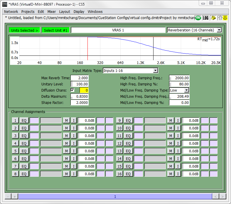 |
VRAS Window
TIP: When a VRAS module is offline, a message denoting the module’s status now appears at the top of the window.
Global parameters
Global parameters pertain to the current VRAS display.
Parameter | Definition |
|---|---|
Label | The VRAS window shows all current parameter values for each instance of VRAS config- ured in the system. |
Type | Early Reflection, Reverberation (16 Channels), or Reverberation (32 Channels). |
Reverberation parameters (16 or 32 Channels)
Reverberation parameters change the channel assignment, time domain characteristics, and frequency domain characteristics of the reverberation.
Reverberation Parameter | Definition |
|---|---|
Input Matrix Type (16 channel only) | Specifies the input cross-coupling matrix. Selection of this matrix controls the distribution of direct signals from the VRAS inputs to the VRAS outputs. All matrix options maintain the same amount of total power at all outputs. Therefore, while the option Inputs 1-16 can be selected with only input 1 active, this will result in less power output than if the Inputs Channel 1 option is selected. A full table of Input options is provided later in this chapter. |
Max Reverb Time | Adjusts the reverberation time. The Time/Frequency graph near the top provides a visual model of the setting. |
Unitary Level: | Adjusts the unitary property of the reverberator. True unity is set at 100.0, which is recommended for normal operation. As the unitary level is reduced, the amplitude response of the reverberator will vary, gain levels will decrease, and the system will behave more like a con- ventional electronic reverb unit. This can be useful if VRAS is used as an in-line effects reverberator |
# Diffusion Chans | This sets the number of channels to be used as Diffusion Channels. |
Reverberation Parameter | Definition |
|---|---|
Delta Maximum | The higher the delta maximum, the more echo density. However, the amount of direct energy in the reverberator increases proportionately to delta maximum, so there is a trade off between echo density and direct-to-reverberant levels. The Delta Maximum control interacts with the Shape Factor control. When you go outside of the normal operating envelope, the graph in the VRAS Editor will not be drawn. |
Shape Factor | Shape factor is the ratio of the longest to the shortest delay. Low shape factors produce similar internal delay times across channels, while high settings produce a wide spread of delay times. The shape factor also defines how quickly the direct levels drop as the channel numbers rise. A high shape factor will give you a rapid drop in loop gains and direct levels. |
High Freq. Damping Frequency | This is the corner frequency for the reverberator damping. You will see the results of the setting on the Time/Frequency graph. You can simultaneously adjust high frequency damping frequency and amount by clicking and dragging directly in the Time/Frequency graph. |
High Freq. Damping Percentage | This is the amount of damping applied to the reverberator at high fre- quencies (above the damping frequency). You will see the results of the setting on the Time/Frequency graph. |
Mid/Low Freq. Damping Type | VRAS has a second damping filter that can be configured as a mid or low band damping. This control sets the type of the filter. Set to Low if you need low frequency damping to compensate for an excessively boomy room. |
Mid/Low Freq. Damping Frequency | This is the corner frequency for the reverberator damping. You will see the results of the setting on the Time/Frequency graph. |
Mid/Low Freq. Damping Percentage | This is the amount of damping applied to the reverberator at high fre- quencies (above the damping frequency). You will see the results of the setting on the Time/Frequency graph. |
Channel Assignments | This specifies up to 16 inputs to be processed by VRAS Reverbera- tion. For each channel row, there is also a channel label, a mute but- ton, channel attenuation value, and two VGroup assignment boxes. |
The combination of reverb time, delta maximum, and shape factor affect how the hardware memory is allocated and used. Some combinations can exceed the memory capacity of the VRAS DSP, truncating some of the reverberator delays and creating distinct echoes. D-Mitri will warn you with messages in the Log window when you enter values that exceed its mem- ory capacity.
TIP: If you have already calculated the desired delays and attenuations, you can copy and paste in data from the spreadsheet.
Early reflections parameters
These parameters change the channel assignment, time domain characteristics, and fre- quency domain characteristics of the early reflections.
Parameter | Definition |
|---|---|
ER Zone Config | Selects the configuration for early reflections zones. |
Input Matrix | Specifies the input cross-coupling matrix. This matrix controls the distribution of direct signals from the VRAS inputs to the VRAS outputs. A full table of Input options is provided later in this chapter. |
Output Matrix | Specifies the output cross-coupling matrix. Selection of this matrix controls the distribution of user-specified delays to VRAS outputs. Two or four independent ER sub-zones can be specified using appropriate Input and Output Matrix options. For instance, if set to Outputs16 then all 16 delays will be matrixed to all 16 outputs. If set to Outputs 8/8, the first eight delays will be matrixed to the first eight outputs, and the last eight delays to the last eight outputs. |
Cutoff Frequency | Adjusts the cutoff frequency of the included low pass filter applied to VRAS inputs. |
High Frequency Attenuation | Adjusts the amount of attenuation of the high frequencies in the low pass filter. |
Channel Assignments | Specifies up to 16 inputs to be processed by VRAS Early Reflections. For each channel row, there is also a channel label, a mute button, channel attenuation value, and two VGroup assignment boxes. |
Early reflection delays and attenuation
For each early reflection signal, you can configure the delay and attenuation, either by typing in different values, or by dragging the points on the graph.
Parameter | Definition |
|---|---|
Min | Minimum (initial) delay time. |
Max | Maximum (final) delay time. |
Spread | Controls the spread of the early reflections between the minimum and maximum delay times. |
Atten | Controls the range of attenuation levels for each early reflection signal. |
VRAS subcues
There are two VRAS subcue types: VRAS Inputs, which capture channel assignments and attenuations, and VRAS Processing, which captures ER and reverberation settings.
Capturing VRAS Subcues
Like other subcues in the system, VRAS parameters are captured using the Capture window. To capture a VRAS Processing subcue:
In the VRAS window, change the parameters to the desired values.
Channel select the VRAS unit(s) you have configured.
Press the F4 key to open the Capture window, and enter a name for the cue.
Deselect all subcue types, and then click in the checkbox next to VRAS Processing.
Click the Capture New button at the bottom of the window.
When using VRAS Reverberation, you can create a preset that turns VRAS off. One way of doing this is to create a cue that includes a System Level subcue that sets the System Level to -inf dB. However, the reverberant tail will be abruptly cut off. A better way of doing this is to set the attenuation of the inputs to VRAS to -inf dB. This way the existing tail will decay naturally when the cue is recalled and the effect will not be so abrupt. For this effect, you will need to capture a VRAS Inputs subcue:
In the VRAS window, set the input channel attenuations to -inf.
Press the F4 key to open the Capture window, and type in a name for the cue (such as VRAS Off).
Deselect all subcue types, and then click in the checkbox next to VRAS Inputs.
Click the Capture New button at the bottom of the window.
If you create a cue that sets all attenuations to -inf, create another cue that restores the atten- uations (a VRAS On cue). This cue can be created using the same method described above, except that you would set each attenuation to the appropriate level before capturing the cue.
Managing CueStation files
CueStation uses several application-specific files to store project data, layouts, and configurations. In addition to saving these files to the computer's hard drive, you can also save projects to flash within a D-Mitri module, with the option to load them automatically when the D-Mitri module boots. CueStation can also save default versions of project and layout files.
Saving files
CueStation layout files and projects can be saved locally, and configuration files can be saved to the D-Mitri modules themselves for quick recall. CueStation also creates its own log files, which can be saved locally.
Saving Files Locally
Project files, layout files, and mixer configuration files can be saved locally to the computer's hard drive. The Projects menu has several different options for saving the current project.
Save Project is available if you have not yet saved a new project. Selecting this option will bring up a dialog box where you type a name for the project and decide where to save it.
Save Project to [project name] option is available if you have opened an existing project file. This option will automatically overwrite that project file with any changes you have made since the last save.
The Save Project As command saves the project under a different file name, in a different location, or both.
Backup Project
The Backup Project command saves a copy of the current project as a backup. Backup projects are saved to CueStation_Settings/D-Mitri_Backups, with an automatically generated name that includes a time and date stamp, in this format: Backup_year_month_- day_hour_min_sec.dmitriProject.
Since saving a project as a backup does not prompt you for a location and file name to save to, backup project files can be used to take a quick snapshot of the state of the system throughout a programming session, which can later be recalled if accidental changes are made that cannot be easily undone.
Saving Projects to Flash
Projects can be saved to the flash memory in the D-Mitri. These projects can be retrieved automatically on startup by configuring the Auto Start settings upon saving.
To save a project to flash, choose Projects Save Project To Flash. The Save Project to D-Mitri Flash Memory window contains the following options.
Option | Definition |
|---|---|
On Power Up | There are two selections: Auto Start Project in Flash, or Do Not Autostart. |
Startup Delay | The startup delay is the time after bootup is complete, but before the startup cue is recalled. The default startup delay is 30 seconds. |
Recall Cue ID on Startup | If desired, enter the name of the cue you want to recall at startup. |
Set Cue List ID on Startup | If desired, enter the name of the cue list you want to recall at startup. |
Completion Message | This message is printed to the log when the Auto Start is triggered. If desired, you can enter a different message here. |
AutoStart | This checkbox is enabled when you enter a valid cue list in the corresponding value box. When selected, the first cue in the cue list will be played on startup, along with any other cues or AutoFollow settings. |
A message in the log window will indicate when the operation is complete.
Another benefit of saving a project to flash is that it can be opened by any client on any com- puter that is connected to the D-Mitri, without needing to have the project already saved on a local hard drive.
The Save Project As
At the top of the window is a drop-down box, with the name of the current directory. The area directly to the right contains buttons for the following commands.
Button | Function |
|---|---|
Back | Returns to the previous location. |
Forward | Moves to the next location. |
Up | Goes to a higher level directory. |
New Folder | Creates new folder within the current directory. |
Icon View | Provides a view for viewing files. |
Details View | Provides a view to see details for each file in the list. |
Next, there is a list of the files in the current directory, followed by a File name: text entry box. Enter the name of the file you would like to save to, and then click Save to close the dialog and save the file.
Shortcut Icons
In the left sidebar is a set of directory shortcuts. The default icons point to Computer, User Home, User Desktop, and CueStation_Settings. (For Mac OS users, there's also a Volumes icon.) This gives you quick access to common save areas.
Add shortcuts to the sidebar by dragging the desired folder in from another window. To delete a shortcut, right-click and choose Remove. This removes instant access only to the folder, not to the folder and the data inside.
Recent Files
In the lower half of the Save Project dialog box, there is a list of the five most recently accessed files. These files also have hotkeys associated with them, for easier access. In order to use the hotkeys, hold down the Command key and then type the number of the file twice. The selected file will then be overwritten.
If you want to remove a file from the list, click the gray Eject icon to the right of the file name.
Filter Project Checkbox
At the bottom of the Save Project dialog window is the Filter Project checkbox. When this checkbox is checked, the Filter Project features appear as a pane inside the Save Project dialog. These filtering features give you the option of choosing which parts of the automation data to save.
Note
When you select an item in the Filter Project pane for action, any other project items the selected item references also receive that action. For example, if you choose to load Cue 5, then any subcues in Cue 5 are also loaded, even if those subcues are not explicitly selected in the Subcues tab of the encompassing Save Project dialog window.
Opening files
The options for opening files in CueStation are similar to those for saving files. A project file is divided into four categories of information: automation data, configuration settings, layout information, and port settings. When you open a project, any project information currently in the server will be cleared and replaced by the new project.
The Open Project Dialog Box
In the top left corner, there are controls for navigating to different directories, and a list of files in the current directory. To open a project, select the project you want and click the Open but- ton.
The Recent Files list works as described in “Saving Files” on page 193.
Open Project Options
Below the list of recently used files are six check boxes to toggle different options for opening projects.
Option | Definition |
|---|---|
Load Project | Select whether to load the project database. Uncheck this box if to only load the configuration or the layout. |
Send Configuration | Toggles whether the configuration stored in the project is sent to the D-Mitri modules. If the box is unchecked, the configuration will be opened and visible in the Mixer Configuration window but it will not be sent. |
Filter Project | Specifies which parts of the automation data CueStation will load. See “Cus- tom Project Filter” on page 198 for more information. |
Load Mixer Settings | Specifies whether CueStation will load the project’s mixer settings. If this box is checked, the window will load all of the mixer settings that were in place when the file was last saved. If Load Mixer Settings and Send Configuration check- boxes are unchecked, the current mixer settings will remain untouched when the new file opens. |
Send Configuration | When Send Configuration is checked, but Load Mixer Settings is unchecked, all control points will be reset to their default values. |
Verify Wild Tracks Subcues | Verifies whether Wild Tracks Deck subcues contained in the project can locate all associated files on the Wild Tracks drive(s). If a file is not found, an error message will be printed to the log. |
Load Layout | Specifies whether CueStation will load the layout saved with the project. Uncheck this box to keep the current layout. |
Load Connection Settings | If Load Connection Settings is checked, opened windows will be connected to the server to which they were connected when the layout was saved. If Load Connection Settings is left unchecked, opened windows will be connected to the same server as the current window. |
Custom Project Filter
These options can be accessed in the Open Project dialog using the Filter Project checkbox. If checked, the Filter Project dialog opens and gives you the option of choosing which parts of the automation data you would like to import. For instance, you could choose to not load in Key Mappings if you would rather use ones you have already created. Or, if you only wanted to load in one cue list, you would deselect all of the cues except for the one you want to load (see “Filter Project Checkbox” on page 196).
Merging projects
In CueStation, automation data can be merged from one project into another. This provides a method to import cue lists, cues, subcues, or other automation data in a selective way.
Merged elements also include all referenced elements. For example, importing a cue list will also cause the cues in the cue list to be imported, as well as the contained subcues, and so on.
The Merge Project dialog box has all of the same controls as “The Open Project Dialog Box” on page 196.
The difference between opening a project and merging a project is that during a project merge, the current project data is not cleared from the server.
Effects of a Merge Project Operation
When you start with Project A and choose to merge data from Project B, the existing data in Project A remains unaffected. However, the merged items from Project B are affected in the following ways:
Items with conflicting ID numbers are assigned a new ID number. For example, when merging cue ID 0 into a project that already contains cue IDs 0 and 1, cues in the destina- tion project will be re-assigned to the next available IDs (for example IDs 2 and 3).
Reference IDs are updated so that Items containing references to other imported items will reflect the new ID numbers.
Changes to ID numbers and references will be reported in the log.
Note
Layout and connection settings of a project cannot be merged.
Customizing CueStation
CueStation can be customized to improve workflow by using saved layouts, keyboard short- cuts, project notes and reports, and communication between clients.
Page Group Controls
CueStation windows with the Display > Show Page Group Controls option can be grouped so that the displayed pages synchronize.
The following table describes the behavior of Page Group Controls.
Component | Function | |
|---|---|---|
Page Group Status | Disabled | Window does not affect any other members of the Page Group. Win- dow does not follow any other members of the Page Group. |
Mirror | Window display affects all Group Mirrors and Group Slaves in the Page Group. Window display follows Group Masters and all other Group Mirrors in the Page Group. | |
Slave | Window display follows Group Masters and all other Group Mirrors in the Page Group. | |
Master | Window display affects all Group Mirrors and Group Slaves in the Page Group. | |
Page Group ID | Changes which Page Group the current window is assigned. Ranges from 1–128. | |
has offsets | Offsets the display relative to other members of the Page Group. The first field is horizontal offset, the second is vertical. Offsets can be positive (right/down) or neg- ative (left/up). |
NOTE: Each Page Group can have multiple Group Masters. Each Group Master will affect all Group Slaves, but other Group Masters will remain unaffected.
Layouts
Custom layouts are stored arrangements of windows on the screen. Saving several layouts with different purposes offers the convenience of switching between layouts quickly. For example, a custom layout can be saved for a performance-specific workflow that displays the Transport, Log, System Status, and Meter windows. A second layout can be saved that gives the user quick access to the Cue List, Cue Library, and Subcue Library windows. A custom hotkey or utility button can be set up to quickly switch between these two layouts.
CueStation layouts are saved as dmitriLayout files. You can also save a layout as a default, which can be opened automatically whenever CueStation is launched.
In addition to window selection and placement, a layout file also includes client connection information. For example, if the client is connected to a specific server when you save a layout as default, then whenever you launch CueStation, it will automatically try to connect to that server.
To save a custom layout:
Arrange the CueStation windows into the desired positions.
Choose Layout > Save Layout As.
Type a name for the layout, and save it to the client computer’s hard drive. To save a default layout:
Choose Layout > Save Layout As Default.
Enable the Layout > Use Default Layout on Launch option to have CueStation restore the default layout automatically upon launch.
Mapping Layouts to Hotkeys
The Open Layout subcue makes it possible to open a layout using a custom key mapping (see “Key Mappings Window” on page 204).
To assign a saved layout to a hotkey combination:
Choose Windows > Support Files window.
Drag a dmitriLayout file into the window to add it to the list of support files. The layout file must be included in the support files in order for it to be accessed by CueStation.
Choose Windows > Subcue Library window and create a new Commands subcue, with a Type of CueStation Control and a Command of Open Layout. Take note of the Subcue ID.
Type the name of the layout file in the Layout File Name field. If you would like to simulate the Open More Layout command, uncheck the box next to Close Existing Windows First:.
Open the Key Mappings window and choose Mappings > New Mapping to create a new key mapping.
Use the list in Appendix B, “CueStation Keyboard Shortcuts” to find a key mapping that is not already used by CueStation.
Set the Action to Recall, and the Target Type to Subcue.
For the Target ID, enter the ID number of the Open Layout subcue you created previously.
You have now created a key mapping that opens a saved layout. You can create additional key mappings that open different layouts using the same procedure.
Custom Utility Buttons
User-customizable utility buttons can be added to the bottom of any CueStation window. These buttons are defined with the Custom Utility Button Properties Editor. Layout > Add Cus- tom Utility Button opens the Custom Utility Button Property Editor.
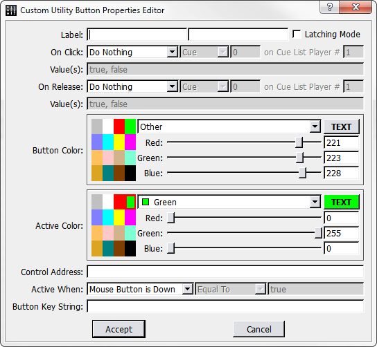 |
Custom Utility Button Properties Editor Window
You can set custom buttons to execute cue or subcue recalls, control points, cue/subcue updates, or text commands. The buttons function by recognizing click and release events, allowing you to assign actions to these events. The actions are: Do Nothing, Do Text Com- mand, Recall, Update, and Set Value.
To add a utility button to a CueStation window:
Choose Layout > Add Custom Utility Button.
Type a new label for the button. Optionally, in the next text box, enter a different name to be displayed when the button is active.
Optionally, select Latching Mode to create a button that stays depressed with the first click and releases with a second click. This behavior is visual only.
Choose an On Click: action: Do Nothing, Recall, Update, or Set Value.
If you chose Recall or Update, select the cue or subcue to be affected. If you chose Set Value, enter the control point's target value.
Optionally, choose an On Release action, which will be triggered when the button is released.
If you wish, alter the color of the button for its normal and active modes. For example, if the button toggles a channel mute, you might wish to make the Active Color red. You can select from the basic, premade colors to the left, or create a custom color using the RGB sliders.
If you chose Set Value above, type the name of the control point in the Control Address text box, and then enter the desired values in the On Click and Release Value fields.
The Active When: parameters control when the button appears active. If it is set to Mouse Button is Down, the button will only be active momentarily. This setting is useful for cue recalls and other momentary actions.
Alternatively, if you want the state of the button to reflect the state of a control point, change Active When: to either Value is or Value is not, and enter a value. Or, set Active When: to Never or Always if you don't want the active state to change. See the next sec- tion, “Utility Button Example” on page 203, for an example on how this function is used.
Optionally, add a Button Key String. Custom utility buttons can be controlled by subcues, and the button key string allows each button to be changed separately.
Click Accept to add the button to the bottom of the window.
Utility Button Example
In this example, there are three cue lists: one Speaker Check cue list and two Show Cue lists. The following procedure will create custom utility buttons that switch between the cue lists when clicked.
Open the Transport window.
Choose Layout > Add Custom Utility Button to open the Utility Button dialog.
Change the Label: from New Button to Speaker Check.
Choose On Click > Set Value.
Enter the ID of the Speaker Check cue list into the On Click Value field.
For the Control Address, type Automation 1 Active CueList ID.
In the next line, select Value is, Equal To, and type the ID of the Speaker Check cue list again.
Click Accept to create the first button. For the other two buttons, these options will mostly stay the same, except:
The button label should reflect the name of the cue list.
The Active When: and Equal To value will be the ID of the Cue List.
When complete, three buttons are displayed at the bottom of the Transport window. Click them to switch between active cue lists.
To edit or delete a custom button, right-click the button and select Edit or Delete.
Key Mappings window
The Key Mappings window provides an area to bind keys to cue and subcue recalls and updates.
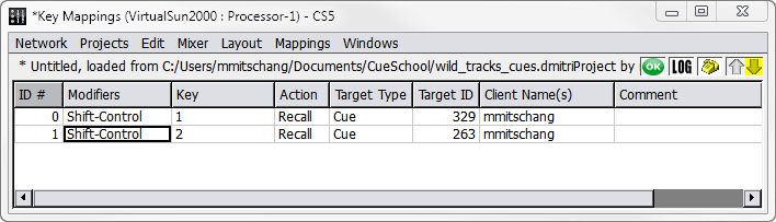 |
Key Mappings Window
Tip
Client Control External Command subcues can be used to bring any window to the front, complete with a specification for the window to display. By using Key Mappings in conjunction with this subcue, you can create a set of custom key map- pings to show you particular sets of windows.
To choose from available Key and Modifier settings, right-click each field. Multiple simultane- ous mappings can be configured for each combination of Modifiers and Keys. Each mapping is represented by a row in the window. Each row consists of several fields.
Field | Description |
|---|---|
ID | A unique index for the mapping. |
Modifiers | Specifies which combination of modifiers are assigned to this mapping. Right-click this field to display the available set of modifiers in a context menu. |
Key | Specifies which keystroke is pressed in conjunction with the modifiers to trigger the mapping’s action. Right-click this field to display the available set of keys in a con- text menu. |
Action | Specifies whether to Recall or Update the specified target cue or subcue. |
Target Type | Specifies whether Target ID refers to a cue or subcue. |
Target ID | Specifies the ID of the target cue or subcue. |
Client Name(s) | Either the IP address of a particular computer running CueStation, or any computer running CueStation detected on the network. |
Comment | An editable text field for a comment. |
NOTE: A complete list of the default key mappings can be found in Appendix B, “CueStation Keyboard Shortcuts.”
Mappings Menu
The Mappings menu contains commands for mapping management.
Command | Function |
|---|---|
New Mapping | Create new mapping. |
Duplicate Mapping | Duplicate the selected mapping. |
Delete Mapping | Delete the selected mapping. |
Project Notes and Reports
The Project Notes window provides an area to type free-form unformatted text. This text is stored within the project file. Project Notes are a convenient place to store information about the configuration of the system, the purpose of certain cues, or other useful information related to the project.
Notes Menu
The Notes menu contains commands for managing project notes.
Command | Function |
|---|---|
Clear Notes | Remove all notes. |
Save Notes As | Save the notes to a new text file. |
Save Notes | Save the notes over the previously saved version. |
Generate Report
Projects > Generate Project Report will create a text file that includes information about the project, including project notes, mixer configuration, cue lists, cues, subcues, and control points. This report is useful for archival purposes, or for transforming the information into a different format, such as a spreadsheet or database.
Chat and paging
The Chat window provides a means for communication between members of the cue-pro- gramming team.
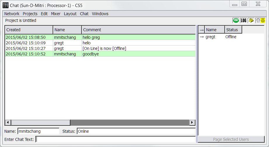 |
Chat Window
The window provides three panels of information:
Chat Log, containing the chat messages with a timestamp and the sender’s name.
Member Log, listing the Name and Status for each member of the team.
Message Entry area, providing Name:, Status:, and Enter Chat Text: boxes.
Page Selected Users button, for paging members of the team.
To send a message to the team, type your name in the (smaller) Name: box and your message in the Enter Chat Text: box. Press Enter and your message will be displayed in the Chat Log panel of your team members’ Chat windows.
To page another user, click the Page Selected Users button, and select the name of the per- son you wish to page. On the paged person's screen, all CueStation windows will flash cyan once, and the telephone icon will flash continuously until the page is answered.
Chat Menu
The Chat menu contains commands for managing the displayed chat log.
Command | Function |
|---|---|
Clear Chat | Clears the chat log. |
Save Chat As | Saves the chat log to a new text file. |
Save Chat | Saves the chat log over the previously saved version. |
Setting system Access Policies
CueStation provides an Access Policies window to allow you to set up different levels of access permissions or restrictions.
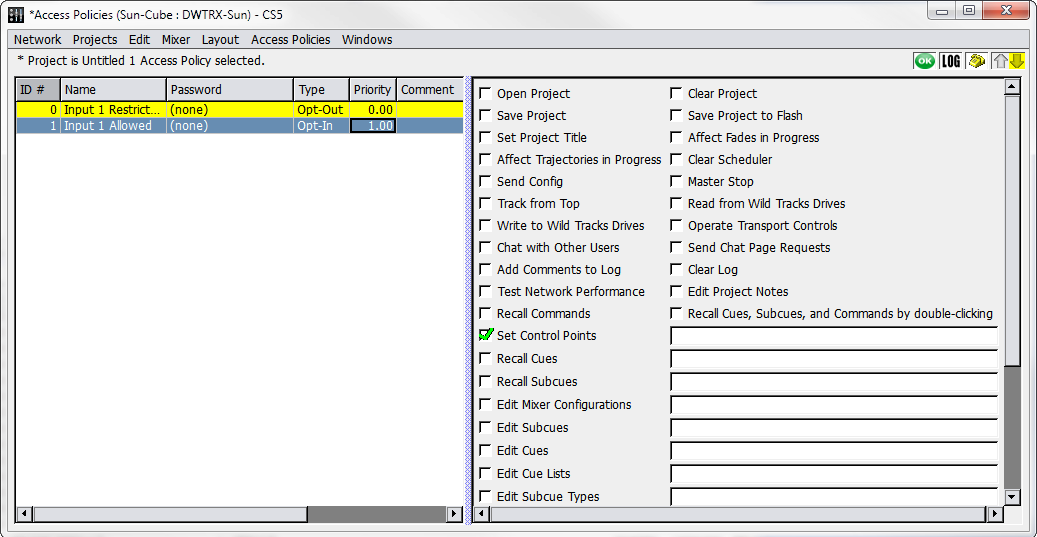 |
Access Policies Window
By defining access polices, you can prevent accidental or unauthorized changes to the sys- tem, while allowing full unrestricted access in the default state. You can use the window to define access policies at any time; it is not necessary to configure access policies before using the software or hardware.
Creating Access Policies
Access policies can be configured to restrict or allow access to everything from changing control points to changing system configuration. This example demonstrates how to restrict unauthorized access to certain control points.
To create an Access policy:
Open the Access Policies window.
Choose Access Policies > New Access Policy. Change the name to Input 1 Restricted.
Double-click the Password column and add a password.
Right-click the Type column and choose Opt-Out. The background of the access policy changes to yellow, indicating that the policy is invoked. No restrictions are yet in place, because nothing in this access policy has been selected.
Click twice in the checkbox for Set Control Points. The red X indicates that the policy restricts this action.
In the box to the right of Set Control Points, type Input 1 Level. Access to Input 1 Level is now restricted. Choose Windows > Inputs and verify that the fader for Input 1 is greyed out.
Choose Access Policies > New Access Policy. Change the name to Input 1 Allowed.
Double click the Password column and type a password.
Right-click the Priority column and select 1.00. This Input 1 Allowed access policy now has priority over the Input 1 Restricted access policy.
Click the checkbox for Set Control Points. The green check indicates that this action is allowed.
Type Input 1 Level in the box to the right.
Choose Access Policies > Reset All Access Policies to clears the cookies for the pass- words you entered, so that anyone using the CueStation client must re-enter the pass- words to gain access to restricted items.
Input 1 is now restricted for all CueStation clients, and this setting is saved with the project, since it is applied by default.
To regain access to Input 1:
Choose Windows > Access Policies to open the Access Policies window, then select Input 1 Allowed.
Choose Access Policies > Invoke Selected Access Policies. A dialog box appears, prompting for the password. Choose from the following options:
CUESTATION 5.5 USER GUIDE
Retain password until I manually reset it
Use password for this session only.
Enter the password and click login options. The background of Input 1 Allowed turns green to show that it is invoked, but not applied by default.
Note
Access Policies that are not applied by default are applied on a per-client basis. For example, after invoking the Input 1 Allowed policy, the client is now permitted to change the level of Input 1, but the permissions of other clients are not affected.
Securing the system
Access Policies in CueStation do not provide complete security from malicious attacks. How- ever, there are a few things you can do to prevent other users from accidentally gaining access to restricted items:
Create an access policy that has Edit Access Policies restricted. Without this invoked, it is possible to delete access policies, change the priority, or change the password.
If Set Control Points is restricted, control points cannot be changed by users, but they can be changed by recalled cues and subcues. For instance, if you have an access policy that restricts access to Input 1, other users cannot change Input 1 directly, but it would be pos- sible to create a subcue that changes the fader level, or bus assigns, etc. Therefore, the access policy restricting control points should also restrict Edit Subcues. With this restricted, it is possible to capture new cues using the capture window, but editing the subcues is disabled.
If there is more than one person using the same CueStation client, make sure to use the Reset All Access Policies function when you have finished editing to reset the cookies for the password(s) you entered.
Recovering lost passwords
If you are the administrator of the D-Mitri system and have lost the password(s) to your access policies, or have been locked out of your system with access policies, there is a password recovery feature available. To regain access to your system:
Choose Windows > Access Policies to open the Access Policies window.
Choose Access Policies > Recover Lost Password. A dialog box appears with instructions and an access code.
Write down the access code, or click Copy Access Code to Clipboard to prepare for pasting it into an email.
Contact Meyer Sound Technical Support and provide the access code. A new password is provided to override the access policies in place and regain access to your system.
Note
The access code and recovery password are valid only until the system is rebooted, and is randomly generated on startup. This prevents users who know one recovery password from accessing other systems.
D-Mitri client/server system
A client/server system is one that uses a central program to keep track of data and which is designed to pass the data to other programs when requested.
The program that manages the data is called a server. The programs sending and receiving data are called clients. A server can support requests from many simultaneous clients, which all accurately reflect the state of the system. For example, multiple CueStation clients can connect to and control D-Mitri simultaneously.
In the D-Mitri, there are Server programs that manage the automation, the mixer settings, Wild Tracks, CueConsole and the user interface. These programs start automatically. The program CueStation is a client.
D-Mitri client/server connections
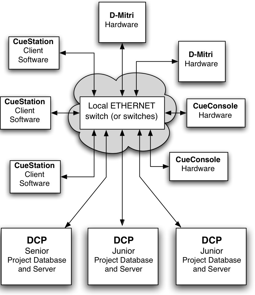 |
There are many advantages to a client/server system for a sound mixing and automation system. Redundant control is possible. Since there can be more than one simultaneous client, a backup computer can be connected and running at the same time without the need for any special software or hardware. There is a natural ease of connection between all elements in the system. Since all parts of the system communicate with the server, a well-designed system makes it easy to connect everything. Multiple users can work on the same system at the same time and everyone sees what controls are being changed as the changes are made.
Backup of the automation data is simple since each connected client can save the project file locally. Accurate indication of control settings is guaranteed for all users since all clients are connected to the same server that is responsible for the control of the audio.
An additional benefit of the D-Mitri Client/Server system is that client interaction is distributed across multiple processor modules, which not only spreads the processing load but also enables any processor to take over for another, should a disconnection or hardware fault occur during use. During such a failover, connected clients can resume without serious interruption.
IPv4 addresses
Each device on the internet must have a unique address. These are used to pass messages from one device to another and are interpreted in order much like a mailing address.CueStation recognizes both the emerging IPv6 address standard, and the older IPv4 address standard. An IPv4 address is shown as four sets of numbers in the range of 0 to 255.
Subnet mask and gateway
The subnet mask is used to set the boundaries for the local address. Any messages for addresses outside of the local boundary are sent to the gateway. Messages pass to the local area through holes in the mask (zeros). The subnet mask is shown in four sets of decimal numbers in the range 0–255, the same way as IP addresses are shown.
Network ports
Network ports enable two or more networked devices to establish a line of communication. Both CueStation and the server processes rely on several network ports for communication. If the computer, network switch, or router use a firewall, they might need to be reconfigured to enable the following ports.
Port | System Use |
|---|---|
TCP 22 | SSH and firmware updates, used for Module Commissioning. |
TCP 23 | SSH and firmware updates, used for Module Commissioning. |
TCP 3020 | Used for network-mounting a Wild Tracks drive via Samba/CIFS (e.g. Command+K on a Mac desktop, log in as a guest). |
UDP 3020 | Used for network-mounting a Wild Tracks drive via Samba/CIFS (e.g. Command+K on a Mac desktop, log in as a guest). |
UDP 5353 | mDNS discovery port, used for Module Commissioning. |
Port | System Use |
|---|---|
UDP 8080 | Web server port. |
UDP 16000 | Allows CueStation clients outside the firewall to discover D-Mitri boxes that are inside the fire- wall. |
UDP 17000 | Used by CueStation clients to ping dcued/dmixerd for D-Mitri status. |
TCP 18000 | CueStation uses this port as a system control/debug port. |
TCP 18001 | dcued process port, used to adjust the current project. |
TCP 18002 | dmixerd process port, used to adjust the current state of the mixing system. |
TCP 18004 | dwtrxd process port, used by the Setup Drives dialog in the Wild Track window. |
TCP 18033 | OSC clients send OSC messages to the system on this port. |
UDP 18033 | OSC clients send OSC messages to the system on this port. |
TCP 18034 | Text-command port, used to send text commands to the system. |
UDP 18034 | Text-command port, used to send text commands to the system. |
TCP 18037 | wsndfiled process port, used for Wild Tracks drive contents and audio preview functions. |
TCP 28000 | Allows remote dmitriproxy clients to connect to D-Mitri's local dmitriproxy client. |
Supported audio file types
The following file formats and encodings are supported for use with both AudioMove and Wild Tracks.
Microsoft WAV
Unsigned 8 bit PCM
Signed 16 bit PCM
Signed 24 bit PCM
Signed 32 bit PCM
32 bit float
64 bit double precision
u-law encoding
A-law encoding
IMA ADPCM
MS ADPCM
GSM 6.10
G721 ADPCM 32kbps
SGI/Apple AIFF/AIFC
Unsigned 8 bit PCM
Signed 8 bit PCM
Signed 16 bit PCM
Signed 24 bit PCM
Signed 32 bit PCM
32 bit float
64 bit double precision
u-law encoding
A-law encoding
GSM 6.10
12 bit DWVW
16 bit DWVW
24 bit DWVW
Sun/DEC/NeXT AU/SND
Signed 8 bit PCM
Signed 16 bit PCM
Signed 24 bit PCM
Signed 32 bit PCM
32 bit float
64 bit double precision
u-law encoding
A-law encoding
G721 ADPCM 32kbps
G723 ADPCM 24kbps
G723 ADPCM 40kbps
Headerless RAW
Unsigned 8 bit PCM
Signed 8 bit PCM
Signed 16 bit PCM
Signed 24 bit PCM
Signed 32 bit PCM
32 bit float
64 bit double precision
u-law encoding
A-law encoding
GSM 6.10
12 bit DWVW
16 bit DWVW
24 bit DWVW
Ok Dialogic ADPCM
Paris Audio File PAF
Signed 8 bit PCM
Signed 16 bit PCM
Signed 24 bit PCM
Commodore Amiga IFF/SVX
Signed 8 bit PCM
Signed 16 bit PCM
Sphere Nist WAV
Signed 8 bit PCM
Signed 16 bit PCM
Signed 24 bit PCM
Signed 32 bit PCM
u-law encoding
A-law encoding
IRCAM SF
Signed 16 bit PCM
Signed 24 bit PCM
Signed 32 bit PCM
32 bit float
u-law encoding
A-law encoding
Creative VOC
Unsigned 8 bit PCM
Signed 16 bit PCM
u-law encoding
A-law encoding
SoundForge W64
Unsigned 8 bit PCM
Signed 16 bit PCM
Signed 24 bit PCM
Signed 32 bit PCM
32 bit float
64 bit double precision
u-law encoding
A-law encoding
IMA ADPCM
MS ADPCM
GSM 6.10
GNU Octave 2.0 MATLAB 4.2
Signed 16 bit PCM
Signed 32 bit PCM
32 bit float
64 bit double precision
GNU Octave 2.1 MATLAB 5.0
Unsigned 8 bit PCM
Signed 16 bit PCM
Signed 32 bit PCM
32 bit float
64 bit double precision
Portable Voice Format PVF
Signed 8 bit PCM
Signed 16 bit PCM
Signed 32 bit PCM
Fasttracker2
8 bit DPCM
16 bit DPCM
HMM Tool Kit HTK
Signed 16 bit PCM
Apple CAF
Signed 8 bit PCM
Signed 16 bit PCM
Signed 24 bit PCM
Signed 32 bit PCM
32 bit float
64 bit double precision
u-law encoding
A-law encoding
CueStation keyboard shortcuts
This section lists the default keyboard shortcut commands used by CueStation. The hotkey combinations listed are for both the Mac and Windows versions of CueStation.
ALL WINDOWS
Function | Shortcut (Mac) | Shortcut (Windows) |
|---|---|---|
Open Capture Window (Update Subcue Mode) | F1 | F1 |
Open Capture Window (Capture Differences Mode) | F2 | F2 |
Open Capture Window (Capture New Mode) | F3 | F3 |
Open Capture Window (Capture New into Cue List Mode) | F4 | F4 |
Switch to Previous Window | F11 | F11 |
Switch to Next Window | F12 | F12‘ |
Edit > Select All | Command+A | Ctrl+A |
Projects > Backup Project | Command+B | Ctrl+B |
Edit > Copy | Command+C | Ctrl+C |
Edit > Duplicate | Command+D | Ctrl+D |
Edit > Enable | Command+E | Ctrl+E |
Edit > Select (Find) | Command+F | Ctrl+F |
Windows > Hide All Windows | Command+H | Ctrl+H |
Windows > Maximize Window | Command+M | Ctrl+M |
Edit > New | Command+N | Ctrl+N |
Projects > Open | Command+O | Ctrl+O |
Mixer > Pause Fades | Command+P | Ctrl+P |
CueStation Quit (Mac OS X), Network Quit (Windows) | Command+Q | Ctrl+Q |
Projects > Save | Command+S | Ctrl+S |
Edit > Unlock Items | Command+U | Ctrl+U |
Edit > Paste | Command+V | Ctrl+V |
Function | Shortcut (Mac) | Shortcut (Windows) |
|---|---|---|
Windows > Close Window | Command+W | Ctrl+W |
Edit > Cut | Command+X | Ctrl+X |
Edit > Redo | Command+Y | Ctrl+Y |
Edit > Undo | Command+Z | Ctrl+Z |
Windows > Listen Masters | Command+0 | Ctrl+0 |
Windows > Grand Master | Command+1 | Ctrl+1 |
Windows > Inputs | Command+2 | Ctrl+2 |
Windows > Wild Tracks | Command+3 | Ctrl+3 |
Windows > Virtual Groups | Command+4 | Ctrl+4 |
Windows > Bus Masters | Command+5 | Ctrl+5 |
Windows > Matrix | Command+6 | Ctrl+6 |
Windows > Output Masters | Command+7 | Ctrl+7 |
Windows > Aux Matrix | Command+8 | Ctrl+8 |
Windows > Aux Masters | Command+9 | Ctrl+9 |
Windows > VRAS | Command+- | Ctrl+- |
Mixer > Finish Fades | Command+; | Ctrl+; |
Layout > Add Custom Utility Button | Command+' | Ctrl+’ |
Edit > Enable | Command+, | Ctrl+, |
Edit > Disable | Command+. | Ctrl+. |
Mixer > Cancel Fades | Command+/ | Ctrl+/ |
Edit > Delete | Command+Delete | Ctrl+Delete |
Windows > Log | Option+0 | Alt+0 |
Windows > Subcue Library | Option+1 | Alt+1 |
Windows > Cue Library | Option+2 | Alt+2 |
Windows > Cue List | Option+3 | Alt+3 |
Windows > Capture | Option+4 | Alt+4 |
Windows > SpaceMap | Option+5 | Alt+5 |
Function | Shortcut (Mac) | Shortcut (Windows) |
|---|---|---|
Windows > Transport | Option+6 | Alt+6 |
Windows > Commands | Option+7 | Alt+7 |
Windows > System Status | Option+8 | Alt+8 |
Windows > Chat | Option+9 | Alt+9 |
Focus: Display Menu | Option+D | Alt+D |
Isolate (Meters Windows) | Option+I | Alt+I |
Focus: Layout Menu | Option+L | Alt+L |
Focus: Mixer Menu | Option+M | Alt+M |
Focus: Network Menu | Option+N | Alt+N |
Focus: Projects Menu | Option+P | Alt+P |
Show EQ (Meters Windows) | Option+S | Alt+S |
Focus: Show Strip (Meters Windows) | Option+T | Alt+T |
Mute (Meters Windows) | Option+U | Alt+U |
Focus: Windows Menu | Option+W | Alt+W |
Windows > Listen Processing | Shift+Command+0 | Shift+Ctrl+0 |
Windows > Input Processing | Shift+Command+2 | Shift+Ctrl+2 |
Windows > Bus Processing | Shift+Command+5 | Shift+Ctrl+5 |
Windows > Output Processing | Shift+Command+7 | Shift+Ctrl+7 |
Windows > Aux Processing | Shift+Command+9 | Shift+Ctrl+9 |
Windows > VRAS Input Processing | Shift+Command+- | Shift+Ctrl+- |
Windows > Clone Window | Shift+Command+= | Shift+Ctrl+= |
Edit > Batch Modify Control Point Entries | Shift+Command+B | Shift+Ctrl+B |
Network > Connect | Shift+Command+C | Shift+Ctrl+C |
Network > Disconnect | Shift+Command+D | Shift+Ctrl+D |
Windows > Full Screen Mode | Shift+Command+F | Shift+Ctrl+F |
Edit > Individualize Subcues | Shift+Command+I | Shift+Ctrl+I |
Windows > Zoom Window | Shift+Command+M | Shift+Ctrl+M |
Function | Shortcut (Mac) | Shortcut (Windows) |
|---|---|---|
Edit > Share Subcues | Shift+Command+O | Shift+Ctrl+O |
Mixer > Resume Fades | Shift+Command+P | Shift+Ctrl+P |
Projects > Save As | Shift+Command+S | Shift+Ctrl+S |
Edit > Lock Items | Shift+Command+U | Shift+Ctrl+U |
Windows > Reset Window | Shift+Command+W | Shift+Ctrl+W |
Layout > Open More Layout | Shift+Command+- | Shift+Ctrl+- |
Mixer > Stop All Cue List Players | Shift+Command+/ | Shift+Ctrl+/ |
Network > Disconnect All | Shift+Option+Com- mand+D | Ctrl+Alt+Shift+D |
Mixer > Master Stop | Shift+Option+Com- mand+M | Ctrl+Alt+Shift+M |
Layout > Open More Layout | Shift+Option+Com- mand+O | Ctrl+Alt+Shift+O |
Mixer > Silence | Shift+Option+Com- mand+S | Ctrl+Alt+Shift+S |
Mixer > Track From Top | Shift+Option+Com- mand+T | Ctrl+Alt+Shift+T |
Windows > Mixer Configuration | Com- mand+Option+0 | Ctrl+Alt+0 |
Windows > Input Meters | Com- mand+Option+1 | Ctrl+Alt+1 |
Windows > Bus Meters | Com- mand+Option+2 | Ctrl+Alt+2 |
Windows > Output Meters | Com- mand+Option+3 | Ctrl+Alt+3 |
Windows > Aux Meters | Com- mand+Option+4 | Ctrl+Alt+4 |
Windows > Listen Meters | Com- mand+Option+5 | Ctrl+Alt+5 |
Windows > Support Files | Com- mand+Option+6 | Ctrl+Alt+6 |
Function | Shortcut (Mac) | Shortcut (Windows) |
|---|---|---|
Windows > Script Execution | Com- mand+Option+7 | Ctrl+Alt+7 |
Windows > Key Mappings | Com- mand+Option+8 | Ctrl+Alt+8 |
Windows > Project Notes | Com- mand+Option+9 | Ctrl+Alt+9 |
Layout > Open Layout | Com- mand+Option+O | Ctrl+Alt+ |
Windows > Access Policies | Com- mand+Option+- | Ctrl+Alt+ |
ACCESS POLICIES WINDOW
Function | Shortcut (Mac) | Shortcut (Windows) |
|---|---|---|
Access Policies > Invoke Selected Access Policies | Command+I | Ctrl+I |
Access Policies > Rescind Selected Access Policies | Command+R | Ctrl+R |
Access Policies > Reset Selected Policies | Shift+Command+R | Shift+Ctrl+R |
CAPTURE WINDOW
Function | Shortcut (Mac) | Shortcut (Windows) |
|---|---|---|
Focus: Name | Option+A | Alt+A |
Focus: Choose Cue | Option+C | Alt+C |
AutoHide Window | Option+H | Alt+H |
Capture Isolated Channels | Option+I | Alt+I |
Uncheck All Subcue Types | Option+K | Alt+K |
Focus: Comment | Option+O | Alt+O |
Focus: Recall | Option+R | Alt+R |
Persistent Subcue Select | Option+S | Alt+S |
Details Button | Option+T | Alt+T |
Function | Shortcut (Mac) | Shortcut (Windows) |
|---|---|---|
Use Channel Selects | Option+U | Alt+U |
Focus: Share Existing Subcues | Option+X | Alt+X |
Focus: Cue List Player | Option+Y | Alt+Y |
CHAT WINDOW
Function | Shortcut (Mac) | Shortcut (Windows) |
|---|---|---|
Focus: Name | Option+A | Alt+A |
Page Selected Users | Option+G | Alt+G |
Focus: Status | Option+S | Alt+S |
Focus: Enter Chat Text | Option+T | Alt+T |
CUE LIBRARY WINDOW
Function | Shortcut (Mac) | Shortcut (Windows) |
|---|---|---|
Subcue Entries > Capture Differences | Command+I | Ctrl+I |
Subcue Entries > Update Subcues | Command+J | Ctrl+J |
Subcue Entries > Recall Subcue Entry | Command+R | Ctrl+R |
Subcue Entries > Instant Recall Subcue Entry | Command+T | Ctrl+T |
Cues > Recall Cue | Shift+Command+R | Shift+Ctrl+R |
Cues > Instant Recall Cue | Shift+Command+T | Shift+Ctrl+T |
Add Entry (in subcue editor) | Option+A | Alt+A |
Focus: Enabled (in subcue editor) | Option+B | Alt+B |
Focus: Cues Menu | Option+C | Alt+C |
Delete Selected | Option+D | Alt+D |
Focus: Choose Files (for Wild Tracks subcue) | Option+F | Alt+F |
Focus: Display (for Mixer Parameter subcue), or Focus: Lock to Timecode (for Wild Tracks subcue) | Option+I | Alt+I |
Function | Shortcut (Mac) | Shortcut (Windows) |
|---|---|---|
Focus: Deck Key (for Wild Tracks subcue) | Option+K | Alt+K |
Resolve Duplicates (for Mixer Parameter subcue), or Focus: Deck Play Offset (for Wild Tracks subcue) | Option+O | Alt+O |
Recall Selected (for subcues) | Option+R | Alt+R |
Focus: Subcues Entries Menu | Option+S | Alt+S |
Focus: Channel Select (for subcues) | Option+T | Alt+T |
Update Subcue (for Wild Tracks subcue) | Option+V | Alt+V |
Focus: Any Deck (for Wild Tracks subcue) | Option+Y | Alt+Y |
CUE LIST WINDOW
Function | Shortcut (Mac) | Shortcut (Windows) |
|---|---|---|
Cue Entries > Stab Timecode | Command+G | Ctrl+G |
Subcue Entries > Capture Differences | Command+I | Ctrl+I |
Subcue Entries > Update Subcues | Command+J | Ctrl+J |
Subcue Entries > Recall Subcue Entry | Command+R | Ctrl+R |
Subcue Entries > Instant Recall Subcue Entry | Command+T | Ctrl+T |
Cue Entries > Recall Cue Entry | Shift+Command+R | Shift+Ctrl+R |
Cue Entries > Instant Recall Cue Entry | Shift+Command+T | Shift+Ctrl+T |
Add Entry (in subcue editor) | Option+A | Alt+A |
Focus: Deck Enabled (in subcue editor) | Option+B | Alt+B |
Delete Selected | Option+D | Alt+D |
Focus: Choose Files (for Wild Tracks subcue) | Option+F | Alt+F |
Show Timecode | Option+H | Alt+H |
Focus: Display (for Mixer Parameter subcue), or Focus: Lock to Timecode (for Wild Tracks subcue) | Option+I | Alt+I |
Focus: Deck Key (for Wild Tracks subcue) | Option+K | Alt+K |
Function | Shortcut (Mac) | Shortcut (Windows) |
|---|---|---|
Resolve Duplicates (for Mixer Parameter subcue), or Focus: Deck Play Offset (for Wild Tracks subcue) | Option+O | Alt+O |
Recall Selected (for subcues) | Option+R | Alt+R |
Focus: Subcues Menu | Option+S | Alt+S |
Focus: Channel Select (for subcues) | Option+T | Alt+T |
Focus: Cue Entries Menu | Option+U | Alt+U |
Focus: Cue List Selector, or Update Subcue (for Wild Tracks subcue) | Option+V | Alt+V |
Focus: Any Deck (for Wild Tracks subcue) | Option+Y | Alt+Y |
INPUTS WINDOW
Function | Shortcut (Mac) | Shortcut (Windows) |
|---|---|---|
Move Flip Row Up | F9 | F9 |
Move Flip Row Down | F10 | F10 |
Display > Show Aux Waits | Command+J | Ctrl+J |
Display > Show Aux Fades | Command+K | Ctrl+K |
Display > Show Aux Pans and Levels | Command+L | Ctrl+L |
MATRIX WINDOW
Function | Shortcut (Mac) | Shortcut (Windows) |
|---|---|---|
Display > Show Waits | Command+J | Ctrl+J |
Display > Show Fades | Command+K | Ctrl+K |
Display > Show Levels | Command+L | Ctrl+L |
MIXER WINDOWS
Function | Shortcut (Mac) | Shortcut (Windows) |
|---|---|---|
Page Up | F5 | F5 |
Page Down | F6 | F6 |
Page Left | F7 | F7 |
Page Right | F8 | F8 |
Step Up | Option+F5 | Alt+F5 |
Step Down | Option+F6 | Alt+F6 |
Step Left | Option+F7 | Alt+F7 |
Step Right | Option+F8 | Alt+F8 |
SPACEMAP WINDOW
Function | Shortcut (Mac) | Shortcut (Windows) |
|---|---|---|
Previous Bus | F7 | F7 |
Next Bus | F8 | F8 |
Display > Enable/Disable Snap to Cartesian Grid | Command+G | Ctrl+G |
SpaceMap > Insert Image | Command+I | Ctrl+I |
SpaceMap > Halt Playback | Command+K | Ctrl+K |
Display > Lock SpaceMap | Command+L | Ctrl+L |
SpaceMap > Recall Trajectory | Command+R | Ctrl+R |
SpaceMap > Insert Triset | Command+T | Ctrl+T |
SpaceMap > Zoom Out | Command+[ | Ctrl+[ |
SpaceMap > Zoom In | Command+] | Ctrl+] |
SpaceMap > Reset Zoom | Command+\ | Ctrl+\ |
Display > Enable/Disable Snap to Polar Grid | Shift+Command+G | Shift+Ctrl+G |
AutoRecall checkbox | Option+A | Alt+A |
Focus: AutoRecall Cue ID | Option+C | Alt+C |
SUBCUE LIBRARY WINDOW
Function | Shortcut (Mac) | Shortcut (Windows) |
|---|---|---|
Subcues > Recall Subcue | Command+R | Ctrl+R |
Subcues > Instant Recall Subcue | Command+T | Ctrl+T |
Add Entry (in subcue editor) | Option+A | Alt+A |
Focus: Enabled (in subcue editor) | Option+B | Alt+B |
Delete Selected | Option+D | Alt+D |
Focus: Choose Files (for Wild Tracks subcue) | Option+F | Alt+F |
| Option+H | Alt+H |
Focus: Display (for Mixer Parameter subcue), or Focus: Lock to Timecode (for Wild Tracks subcue) | Option+I | Alt+I |
Focus: Deck Key (for Wild Tracks subcue) | Option+K | Alt+K |
Resolve Duplicates (for Mixer Parameter subcue), or Focus: Deck Play Offset (for Wild Tracks subcue) | Option+O | Alt+O |
Recall Selected (for subcues) | Option+R | Alt+R |
Focus: Subcues Menu | Option+S | Alt+S |
Focus: Channel Select (for subcues) | Option+T | Alt+T |
Update Subcue (for Wild Tracks subcue) | Option+V | Alt+V |
Focus: Any Deck (for Wild Tracks subcue) | Option+Y | Alt+Y |
SUPPORT FILES WINDOW
Function | Shortcut (Mac) | Shortcut (Windows) |
|---|---|---|
Files > Import Files | Command+I | Ctrl+I |
WILD TRACKS WINDOW
Function | Shortcut (Mac) | Compass — Control Software iPad App |
|---|---|---|
Display > Browse Virtual Drive File | Command+I | Ctrl+I |
Display > Bar Graph Layout One Row Per Voice | Command+J | Ctrl+J |
Display > Bar Graph Layout One Row Per Send | Command+K | Ctrl+K |
Display > Bar Graph Layout One Row Per Entry | Command+L | Ctrl+L |
Recall Rehearsal Point | Command+R | Ctrl+R |
Display > Track Display Height Make Bars Shorter | Command+[ | Ctrl+[ |
Display > Track Display Height Make Bars Taller | Command+] | Ctrl+] |
Display > Track Display Height Reset to Default Bar Height | Command+\ | Ctrl+\ |
Set Rehearsal Point | Shift+Command+R | Shift+Ctrl+R |
Choose Files | Option+F | Alt+F |
Lock to Timecode | Option+I | Alt+I |
Focus: Deck Key | Option+K | Alt+K |
Focus: Deck Play Offset | Option+O | Alt+O |
Update Subcue | Option+V | Alt+V |
Any Deck | Option+Y | Alt+Y |
Zoom Deck View In | Option+Com- mand+I | Ctrl+Alt+I |
Pan Deck View Left | Option+Com- mand+J | Ctrl+Alt+J |
Pan Deck View Right | Option+Com- mand+K | Ctrl+Alt+K |
Zoom Deck View Out | Option+Com- mand+U | Ctrl+Alt+U |
Function | Shortcut (Mac) | Shortcut (Windows) |
|---|---|---|
Pan Deck View to Start | Shift+Option+Com- mand+J | Shift+Ctrl+Alt+J |
Pan Deck View to End | Shift+Option+Com- mand+K | Shift+Ctrl+Alt+K |
Zoom Deck View All | Shift+Option+Com- mand+U | Shift+Ctrl+Alt+U |
CueStation keyboard shortcuts: All windows
Function | Shortcut (Mac) | Shortcut (Windows) |
|---|---|---|
Open Capture Window (Update Subcue Mode) | F1 | F1 |
Open Capture Window (Capture Differences Mode) | F2 | F2 |
Open Capture Window (Capture New Mode) | F3 | F3 |
Open Capture Window (Capture New into Cue List Mode) | F4 | F4 |
Switch to Previous Window | F11 | F11 |
Switch to Next Window | F12 | F12‘ |
Edit > Select All | Command+A | Ctrl+A |
Projects > Backup Project | Command+B | Ctrl+B |
Edit > Copy | Command+C | Ctrl+C |
Edit > Duplicate | Command+D | Ctrl+D |
Edit > Enable | Command+E | Ctrl+E |
Edit > Select (Find) | Command+F | Ctrl+F |
Windows > Hide All Windows | Command+H | Ctrl+H |
Windows > Maximize Window | Command+M | Ctrl+M |
Edit > New | Command+N | Ctrl+N |
Projects > Open | Command+O | Ctrl+O |
Mixer > Pause Fades | Command+P | Ctrl+P |
CueStation Quit (Mac OS X), Network Quit (Windows) | Command+Q | Ctrl+Q |
Projects > Save | Command+S | Ctrl+S |
Edit > Unlock Items | Command+U | Ctrl+U |
Edit > Paste | Command+V | Ctrl+V |
Windows > Close Window | Command+W | Ctrl+W |
Edit > Cut | Command+X | Ctrl+X |
Edit > Redo | Command+Y | Ctrl+Y |
Edit > Undo | Command+Z | Ctrl+Z |
Windows > Listen Masters | Command+0 | Ctrl+0 |
Windows > Grand Master | Command+1 | Ctrl+1 |
Windows > Inputs | Command+2 | Ctrl+2 |
Windows > Wild Tracks | Command+3 | Ctrl+3 |
Windows > Virtual Groups | Command+4 | Ctrl+4 |
Windows > Bus Masters | Command+5 | Ctrl+5 |
Windows > Matrix | Command+6 | Ctrl+6 |
Windows > Output Masters | Command+7 | Ctrl+7 |
Windows > Aux Matrix | Command+8 | Ctrl+8 |
Windows > Aux Masters | Command+9 | Ctrl+9 |
Windows > VRAS | Command+- | Ctrl+- |
Mixer > Finish Fades | Command+; | Ctrl+; |
Layout > Add Custom Utility Button | Command+' | Ctrl+’ |
Edit > Enable | Command+, | Ctrl+, |
Edit > Disable | Command+. | Ctrl+. |
Mixer > Cancel Fades | Command+/ | Ctrl+/ |
Edit > Delete | Command+Delete | Ctrl+Delete |
Windows > Log | Option+0 | Alt+0 |
Windows > Subcue Library | Option+1 | Alt+1 |
Windows > Cue Library | Option+2 | Alt+2 |
Windows > Cue List | Option+3 | Alt+3 |
Windows > Capture | Option+4 | Alt+4 |
Windows > SpaceMap | Option+5 | Alt+5 |
Windows > Transport | Option+6 | Alt+6 |
Windows > Commands | Option+7 | Alt+7 |
Windows > System Status | Option+8 | Alt+8 |
Windows > Chat | Option+9 | Alt+9 |
Focus: Display Menu | Option+D | Alt+D |
Isolate (Meters Windows) | Option+I | Alt+I |
Focus: Layout Menu | Option+L | Alt+L |
Focus: Mixer Menu | Option+M | Alt+M |
Focus: Network Menu | Option+N | Alt+N |
Focus: Projects Menu | Option+P | Alt+P |
Show EQ (Meters Windows) | Option+S | Alt+S |
Focus: Show Strip (Meters Windows) | Option+T | Alt+T |
Mute (Meters Windows) | Option+U | Alt+U |
Focus: Windows Menu | Option+W | Alt+W |
Windows > Listen Processing | Shift+Command+0 | Shift+Ctrl+0 |
Windows > Input Processing | Shift+Command+2 | Shift+Ctrl+2 |
Windows > Bus Processing | Shift+Command+5 | Shift+Ctrl+5 |
Windows > Output Processing | Shift+Command+7 | Shift+Ctrl+7 |
Windows > Aux Processing | Shift+Command+9 | Shift+Ctrl+9 |
Windows > VRAS Input Processing | Shift+Command+- | Shift+Ctrl+- |
Windows > Clone Window | Shift+Command+= | Shift+Ctrl+= |
Edit > Batch Modify Control Point Entries | Shift+Command+B | Shift+Ctrl+B |
Network > Connect | Shift+Command+C | Shift+Ctrl+C |
Network > Disconnect | Shift+Command+D | Shift+Ctrl+D |
Windows > Full Screen Mode | Shift+Command+F | Shift+Ctrl+F |
Edit > Individualize Subcues | Shift+Command+I | Shift+Ctrl+I |
Windows > Zoom Window | Shift+Command+M | Shift+Ctrl+M |
Edit > Share Subcues | Shift+Command+O | Shift+Ctrl+O |
Mixer > Resume Fades | Shift+Command+P | Shift+Ctrl+P |
Projects > Save As | Shift+Command+S | Shift+Ctrl+S |
Edit > Lock Items | Shift+Command+U | Shift+Ctrl+U |
Windows > Reset Window | Shift+Command+W | Shift+Ctrl+W |
Layout > Open More Layout | Shift+Command+- | Shift+Ctrl+- |
Mixer > Stop All Cue List Players | Shift+Command+/ | Shift+Ctrl+/ |
Network > Disconnect All | Shift+Option+Com- mand+D | Ctrl+Alt+Shift+D |
Mixer > Master Stop | Shift+Option+Com- mand+M | Ctrl+Alt+Shift+M |
Layout > Open More Layout | Shift+Option+Com- mand+O | Ctrl+Alt+Shift+O |
Mixer > Silence | Shift+Option+Com- mand+S | Ctrl+Alt+Shift+S |
Mixer > Track From Top | Shift+Option+Com- mand+T | Ctrl+Alt+Shift+T |
Windows > Mixer Configuration | Com- mand+Option+0 | Ctrl+Alt+0 |
Windows > Input Meters | Com- mand+Option+1 | Ctrl+Alt+1 |
Windows > Bus Meters | Com- mand+Option+2 | Ctrl+Alt+2 |
Windows > Output Meters | Com- mand+Option+3 | Ctrl+Alt+3 |
Windows > Aux Meters | Com- mand+Option+4 | Ctrl+Alt+4 |
Windows > Listen Meters | Com- mand+Option+5 | Ctrl+Alt+5 |
Windows > Support Files | Com- mand+Option+6 | Ctrl+Alt+6 |
Windows > Script Execution | Com- mand+Option+7 | Ctrl+Alt+7 |
Windows > Key Mappings | Com- mand+Option+8 | Ctrl+Alt+8 |
Windows > Project Notes | Com- mand+Option+9 | Ctrl+Alt+9 |
Layout > Open Layout | Com- mand+Option+O | Ctrl+Alt+ |
Windows > Access Policies | Com- mand+Option+- | Ctrl+Alt+ |
CueStation keyboard shortcuts: Access Policies window
Function | Shortcut (Mac) | Shortcut (Windows) |
|---|---|---|
Access Policies > Invoke Selected Access Policies | Command+I | Ctrl+I |
Access Policies > Rescind Selected Access Policies | Command+R | Ctrl+R |
Access Policies > Reset Selected Policies | Shift+Command+R | Shift+Ctrl+R |
CueStation keyboard shortcuts: Capture window
Function | Shortcut (Mac) | Shortcut (Windows) |
|---|---|---|
Focus: Name | Option+A | Alt+A |
Focus: Choose Cue | Option+C | Alt+C |
AutoHide Window | Option+H | Alt+H |
Capture Isolated Channels | Option+I | Alt+I |
Uncheck All Subcue Types | Option+K | Alt+K |
Focus: Comment | Option+O | Alt+O |
Focus: Recall | Option+R | Alt+R |
Persistent Subcue Select | Option+S | Alt+S |
Details Button | Option+T | Alt+T |
Use Channel Selects | Option+U | Alt+U |
Focus: Share Existing Subcues | Option+X | Alt+X |
Focus: Cue List Player | Option+Y | Alt+Y |
CueStation keyboard shortcuts: Chat window
Function | Shortcut (Mac) | Shortcut (Windows) |
|---|---|---|
Focus: Name | Option+A | Alt+A |
Page Selected Users | Option+G | Alt+G |
Focus: Status | Option+S | Alt+S |
Focus: Enter Chat Text | Option+T | Alt+T |
CueStation keyboard shortcuts: Cue Library window
Function | Shortcut (Mac) | Shortcut (Windows) |
|---|---|---|
Subcue Entries > Capture Differences | Command+I | Ctrl+I |
Subcue Entries > Update Subcues | Command+J | Ctrl+J |
Subcue Entries > Recall Subcue Entry | Command+R | Ctrl+R |
Subcue Entries > Instant Recall Subcue Entry | Command+T | Ctrl+T |
Cues > Recall Cue | Shift+Command+R | Shift+Ctrl+R |
Cues > Instant Recall Cue | Shift+Command+T | Shift+Ctrl+T |
Add Entry (in subcue editor) | Option+A | Alt+A |
Focus: Enabled (in subcue editor) | Option+B | Alt+B |
Focus: Cues Menu | Option+C | Alt+C |
Delete Selected | Option+D | Alt+D |
Focus: Choose Files (for Wild Tracks subcue) | Option+F | Alt+F |
Focus: Display (for Mixer Parameter subcue), or Focus: Lock to Timecode (for Wild Tracks subcue) | Option+I | Alt+I |
Focus: Deck Key (for Wild Tracks subcue) | Option+K | Alt+K |
Resolve Duplicates (for Mixer Parameter subcue), or Focus: Deck Play Offset (for Wild Tracks subcue) | Option+O | Alt+O |
Recall Selected (for subcues) | Option+R | Alt+R |
Focus: Subcues Entries Menu | Option+S | Alt+S |
Focus: Channel Select (for subcues) | Option+T | Alt+T |
Update Subcue (for Wild Tracks subcue) | Option+V | Alt+V |
Focus: Any Deck (for Wild Tracks subcue) | Option+Y | Alt+Y |
CueStation keyboard shortcuts: Cue List window
Function | Shortcut (Mac) | Shortcut (Windows) |
|---|---|---|
Cue Entries > Stab Timecode | Command+G | Ctrl+G |
Subcue Entries > Capture Differences | Command+I | Ctrl+I |
Subcue Entries > Update Subcues | Command+J | Ctrl+J |
Subcue Entries > Recall Subcue Entry | Command+R | Ctrl+R |
Subcue Entries > Instant Recall Subcue Entry | Command+T | Ctrl+T |
Cue Entries > Recall Cue Entry | Shift+Command+R | Shift+Ctrl+R |
Cue Entries > Instant Recall Cue Entry | Shift+Command+T | Shift+Ctrl+T |
Add Entry (in subcue editor) | Option+A | Alt+A |
Focus: Deck Enabled (in subcue editor) | Option+B | Alt+B |
Delete Selected | Option+D | Alt+D |
Focus: Choose Files (for Wild Tracks subcue) | Option+F | Alt+F |
Show Timecode | Option+H | Alt+H |
Focus: Display (for Mixer Parameter subcue), or Focus: Lock to Timecode (for Wild Tracks subcue) | Option+I | Alt+I |
Focus: Deck Key (for Wild Tracks subcue) | Option+K | Alt+K |
Resolve Duplicates (for Mixer Parameter subcue), or Focus: Deck Play Offset (for Wild Tracks subcue) | Option+O | Alt+O |
Recall Selected (for subcues) | Option+R | Alt+R |
Focus: Subcues Menu | Option+S | Alt+S |
Focus: Channel Select (for subcues) | Option+T | Alt+T |
Focus: Cue Entries Menu | Option+U | Alt+U |
Focus: Cue List Selector, or Update Subcue (for Wild Tracks subcue) | Option+V | Alt+V |
Focus: Any Deck (for Wild Tracks subcue) | Option+Y | Alt+Y |
CueStation keyboard shortcuts: Inputs window
Function | Shortcut (Mac) | Shortcut (Windows) |
|---|---|---|
Move Flip Row Up | F9 | F9 |
Move Flip Row Down | F10 | F10 |
Display > Show Aux Waits | Command+J | Ctrl+J |
Display > Show Aux Fades | Command+K | Ctrl+K |
Display > Show Aux Pans and Levels | Command+L | Ctrl+L |
CueStation keyboard shortcuts: Matrix window
Function | Shortcut (Mac) | Shortcut (Windows) |
|---|---|---|
Display > Show Waits | Command+J | Ctrl+J |
Display > Show Fades | Command+K | Ctrl+K |
Display > Show Levels | Command+L | Ctrl+L |
CueStation keyboard shortcuts: Mixer windows
Function | Shortcut (Mac) | Shortcut (Windows) |
|---|---|---|
Page Up | F5 | F5 |
Page Down | F6 | F6 |
Page Left | F7 | F7 |
Page Right | F8 | F8 |
Step Up | Option+F5 | Alt+F5 |
Step Down | Option+F6 | Alt+F6 |
Step Left | Option+F7 | Alt+F7 |
Step Right | Option+F8 | Alt+F8 |
CueStation keyboard shortcuts: Spacemap window
Function | Shortcut (Mac) | Shortcut (Windows) |
|---|---|---|
Previous Bus | F7 | F7 |
Next Bus | F8 | F8 |
Display > Enable/Disable Snap to Cartesian Grid | Command+G | Ctrl+G |
SpaceMap > Insert Image | Command+I | Ctrl+I |
SpaceMap > Halt Playback | Command+K | Ctrl+K |
Display > Lock SpaceMap | Command+L | Ctrl+L |
SpaceMap > Recall Trajectory | Command+R | Ctrl+R |
SpaceMap > Insert Triset | Command+T | Ctrl+T |
SpaceMap > Zoom Out | Command+[ | Ctrl+[ |
SpaceMap > Zoom In | Command+] | Ctrl+] |
SpaceMap > Reset Zoom | Command+\ | Ctrl+\ |
Display > Enable/Disable Snap to Polar Grid | Shift+Command+G | Shift+Ctrl+G |
AutoRecall checkbox | Option+A | Alt+A |
Focus: AutoRecall Cue ID | Option+C | Alt+C |
CueStation keyboard shortcuts: Subcue Library window
Function | Shortcut (Mac) | Shortcut (Windows) |
|---|---|---|
Subcues > Recall Subcue | Command+R | Ctrl+R |
Subcues > Instant Recall Subcue | Command+T | Ctrl+T |
Add Entry (in subcue editor) | Option+A | Alt+A |
Focus: Enabled (in subcue editor) | Option+B | Alt+B |
Delete Selected | Option+D | Alt+D |
Focus: Choose Files (for Wild Tracks subcue) | Option+F | Alt+F |
Focus: Show Filter | Option+H | Alt+H |
Focus: Display (for Mixer Parameter subcue), or Focus: Lock to Timecode (for Wild Tracks subcue) | Option+I | Alt+I |
Focus: Deck Key (for Wild Tracks subcue) | Option+K | Alt+K |
Resolve Duplicates (for Mixer Parameter subcue), or Focus: Deck Play Offset (for Wild Tracks subcue) | Option+O | Alt+O |
Recall Selected (for subcues) | Option+R | Alt+R |
Focus: Subcues Menu | Option+S | Alt+S |
Focus: Channel Select (for subcues) | Option+T | Alt+T |
Update Subcue (for Wild Tracks subcue) | Option+V | Alt+V |
Focus: Any Deck (for Wild Tracks subcue) | Option+Y | Alt+Y |
CueStation keyboard shortcuts: Support files window
Function | Shortcut (Mac) | Shortcut (Windows) |
|---|---|---|
Files > Import Files | Command+I | Ctrl+I |
CueStation keyboard shortcuts: Wild Tracks window
Function | Shortcut (Mac) | Shortcut (Windows) |
|---|---|---|
Display > Browse Virtual Drive File | Command+I | Ctrl+I |
Display > Bar Graph Layout One Row Per Voice | Command+J | Ctrl+J |
Display > Bar Graph Layout One Row Per Send | Command+K | Ctrl+K |
Display > Bar Graph Layout One Row Per Entry | Command+L | Ctrl+L |
Recall Rehearsal Point | Command+R | Ctrl+R |
Display > Track Display Height Make Bars Shorter | Command+[ | Ctrl+[ |
Display > Track Display Height Make Bars Taller | Command+] | Ctrl+] |
Display > Track Display Height Reset to Default Bar Height | Command+\ | Ctrl+\ |
Set Rehearsal Point | Shift+Command+R | Shift+Ctrl+R |
Choose Files | Option+F | Alt+F |
Lock to Timecode | Option+I | Alt+I |
Focus: Deck Key | Option+K | Alt+K |
Focus: Deck Play Offset | Option+O | Alt+O |
Update Subcue | Option+V | Alt+V |
Any Deck | Option+Y | Alt+Y |
Zoom Deck View In | Option+Com- mand+I | Ctrl+Alt+I |
Pan Deck View Left | Option+Com- mand+J | Ctrl+Alt+J |
Pan Deck View Right | Option+Com- mand+K | Ctrl+Alt+K |
Zoom Deck View Out | Option+Com- mand+U | Ctrl+Alt+U |
Pan Deck View to Start | Shift+Option+Com- mand+J | Shift+Ctrl+Alt+J |
Pan Deck View to End | Shift+Option+Com- mand+K | Shift+Ctrl+Alt+K |
Zoom Deck View All | Shift+Option+Com- mand+U | Shift+Ctrl+Alt+U |
D-Mitri text commands
This section describes the various text commands that are accepted by CueStation. Text commands are used in various places, including port 18034, external commands, etc. Variables appear in brackets.
Note
Alias values can be included in any text command by prepending a dollar sign ($) to the alias's name, and the aliases will be expanded when the command is executed. For example, if there is an alias named Meyer with an associated value of 123 in the Active Config, the text command “recall cue $Meyer” is interpreted as “recall cue 123”.
Command | Description |
|---|---|
go [on player N] | Equivalent to pressing a GO button in the Transport window. If (on player N) is specified, then the GO button will be pressed on Cue List Player #N; if not, it will default to Cue List Player #1. |
stop [on player N] | Equivalent to pressing a STOP button in the Transport window. if (on player N) is specified, then the STOP button will be pressed on Cue List Player #N; if not, it will default to Cue List Player #1. |
next [D] [on player N] | Moves the upcoming-cue position (aka the yellow bar) in the Transport window by D positions. For example, “moveby 1” is the same as “next”, and “moveby -1” is the same as “previous”. Attempts to move off the top or bottom of the list will move the yellow bar to the top/bot- tom of the list, so “moveby -99999” is a good way to “skip to the top” of the cue list. If no player ID is specified, the command will be applied to Cue List Player #1. If no delta is specified, a delta of 1 is assumed. |
moveby [D] [on player N] | |
prev [D] [on player N] | This works the same as “next” and “moveby”, except that the sense of the delta values is negated; e.g. “prev 1” will move the yellow bar up one in the Cue List, and “prev -1” will move the yellow bar down one in the Cue List. If no delta is specified, a delta of 1 is assumed. |
previous [D] [on player N] | |
top [on player N] | Moves the upcoming-cue position of specified Cue List Player to the top of the Cue List. If no player ID is specified, the command will be applied to Cue List Player #1. |
bot [on player N] | Moves the upcoming-cue position of specified Cue List Player to the bottom of the Cue List. If no player ID is specified, the command will be applied to Cue List Player #1. |
bottom [on player N] | |
recall (cue,subcue) D [on player N] | Recalls the specified cue or subcue. If the “on player N” suffix is not present, the recall will occur on Cue List Player #1. |
update (cue,subcue) D | Updates the control point values in the specified cue or subcue to the mixer's current state for those values. |
log (text) | Prints the specified text to the system log. The command word used determines the severity level at which the text is logged. |
warn (text) | |
error (text) | |
crit (text) | |
debug (text) | |
trace (text) | |
get [tag=] (addresses) | Requests the current values of the specified addresses. For example, “get input 1-8 level” will cause the current values of the first 8 input fad- ers to be printed. If an optional tag is specified (e.g. “get foo = input 1- 8 level”) then the returned values text will include the specified tag string (e.g. “foo”). |
set (addresses) = (values) | Sets the specified values to the specified addresses. The syntax is sim- ilar to what is seen in Mixer Parameter subcues. For example, “set input 1-8 level = +5.5” or “set output 5,7,9-11 mute = false”. You can specify optional wait and fade times like this: “set input 1 level = -50.0 waitTime=5.5 fadeTime=10.0” (which specifies a wait of 5.5 seconds followed by a fade over 10 seconds). |
increase (addresses) by (values) | Increases the specified addresses by the specified values. For exam- ple, “increase input 1-8 level by +5.5”. You can specify optional wait and fade times like this: “increase input 1 level by +3.0 waitTime=5.5 fadeTime=10.0” (which specifies a wait of 5.5 seconds followed by a +3dB fade over 10 seconds). |
decrease (addresses) by (values) | Decreases the specified addresses by the specified values. For exam- ple, “decrease input 1-8 level by +5.5”. You can specify optional wait and fade times like this: “decrease input 1 level by +3.0 waitTime=5.5 fadeTime=10.0” (which specifies a wait of 5.5 seconds followed by a - 3dB fade over 10 seconds). |
fade (addresses) (up/down/to) (val- ues) over (time period) | This command is a convenience synonym for the “set”, “increase”, or “decrease” commands described above. It can be used to more easily specify control point changes with fades. Some examples: “fade input 1 level to +5dB over 3 seconds” “fade input 1,3,5 level up 5dB over 3 seconds” “fade input 1-4 level down 5dB over 500 milliseconds” “fade input 1-4 level down 20dB” Note that if a time period is not specified, a fade time of 1 second will be used by default. |
subscribe (addresses) | Tells the system to send text messages whenever the specified control point(s) change. Also an initial update is always sent immediately after the subscribe command is received. Example: subscribe input 1-2 level Got: Input 2 Level = -inf Got: Input 1 Level = -inf |
unsubscribe (addresses) | Removes the specified addresses from the current subscribed- addresses set for this client. |
unsubscribeall | Removes all subscribed addresses from the subscribed-addresses set for this client. |
subscribeevent (pattern) | Tells the system to send text messages whenever the events whose event strings match the specified pattern occur. Example: subscribeevent hexbytes* Event: hexbytes unit 1 bytes F0 1F 7E 01 02 F7 |
unsubscribeevent (pattern) | Cancels a previously subscribed event pattern. (The string passed to this command should be one that was previously passed to “sub- scribeevent”). Note that wildcards specified in (pattern) are not expanded to match multiple previous patterns that were passed to “subscribeevent”; rather, at most only a single pattern will be unsub- scribed. Example: unsubscribeevent hexbytes* |
unsubscribeallevents | Cancels all previously created event subscriptions for this client. |
watch (nodepath) [quietly] | Starts watching the specified nodes in the project. Whenever a project node whose path matches (nodepath) is created, changed, or destroyed, update text will be generated to notify you about the change. Example: watch log/* log/I0: QNetLogEntry: name=[Received state #0 of primary database from the senior peer.] when=[2010/08/31 12:56:39] severity=[info] sourceName=[dcasld@Processor-1] msgSerNum=[0] sourceSer- Num=[1000] scloc=[JBTS] log/I1: QNetLogEntry: name=[Sending state #0 of primary database to peer 429-493-4527.] when=[2010/08/31 12:56:39] severity=[info] sourceName=[dcued@Processor-1] msgSerNum=[1] sourceSer- Num=[1000] scloc=[JBG8] If the “quietly” keyword is specified, then existing nodes won't be printed; only future updates will be printed. If you watch a node that has a child-nodes-index, then instructions for reproducing that index will be printed also. For example: watch default/cuelists/0 default/cuelists/0: QNetCueList: name=[Default Cue List] index/default/cuelists/0: Clear Index index/default/cuelists/0: Insert child I18 at position 0 index/default/cuelists/0: Insert child I5 at position 1 index/default/cuelists/0: Insert child I19 at position 2 [...] index/default/cuelists/0: Remove child I19 from position 2 index/default/cuelists/0: Insert child I19 at position 10 |
unwatch (nodepath) | Cancels a previously set watch path. |
unwatchall | Cancels all previous set watch paths for this client. |
print (nodepath) (maxdepth=D) | Prints all nodes matching (nodepath), and recursively prints their child nodes as well. You can optionally specify a maxdepth=D argument to limit the maximum depth of the recursion; by default it will recurse as far as it can. Example: print default/subcues/0 default/subcues/0: QNetSubcueHeader: name=[jr_FIRE DRILL!] type=[1] typeString=[Commands] default/subcues/0/scd: [External_Control / Print Message To Log]: enabled=1 waitTime=0 Cmt=[] tttMode=1 tttKey=[] user=0 |
ping [tag] | Sends a “Ping” to dmixerd which is immediately echoed back with a corresponding “Pong”. You can optionally specify a tag string, which will be included in the Pong result. |
projectping [tag] | This is similar to the “ping” command, except that the ping is routed through dcued and back, rather than just through dmixerd. This can be helpful when you want to be notified that dcued has finished process- ing a command that you previously sent it. |
heypython (slotindex) [message] | This command sends a text message to the Python script running in slot (slotindex) in the script execution window. The message can be any string you like; it will be passed in as the argument in a call to User- CommandReceived() in the Python script. The default implementation of UserCommandReceived() in the BasicClient class will try to execute the string as Python source code; however scripts can (and often do) override UserCommandReceived in a subclass of BasicClient to to handle the incoming text in a different manner. Some values for (slotindex) that have special meanings are: -1 = send to all python scripts (whether shown in the Script Execution window or not) -2 = send to all “foreground” python scripts (i.e. all scripts shown in the Script Execution window) -3 = send to all “background” python scripts (i.e. all scripts not shown in the Script Execution window) |
runpython (slotindex) (filename) [arguments] | Launches a new Python script process in the specified slot in the Script Execution window. A slotindex value of -1 will cause the script to be run “in the background” (i.e. not shown in the Script Execution win- dow). The filename should be the name of a python script in the Sup- port Files window, or in the templates folder. |
trigger (eventstring) | Sends a trigger-event to the CueStation system. Any triggers (previ- ously set up with the “External Control /Setup Triggers” command) that match (eventstring) will be activated. |
wait (time period) | Pauses the OSC parser for this client for the specified period of time. For example, “wait 5” will cause no more OSC commands to be exe- cuted after this one (for this client) until 5 seconds have passed. “Wait 100 milliseconds” would cause a 100 mS pause. If no argument is provided, then a wait time will be calculated so that command execution resumes immediately after the (“set”, “increase”, “decrease”, or “fade”) command most recently sent by this client fin- ishes its wait/fade execution. |
cancel (all) | Cancels any current time period for this client (caused a previous “wait” command) as well as any commands that had been queued up to exe- cute when the time period completed. If the keyword “all” is specified (i.e. “cancel all”) then all OSC clients in the system will have the “cancel” operation applied to them, rather than only the current client. |
osc (commandpath) [osc_args] | This command tells CueStation to execute an OpenSoundControl command that is specified in the comma-separated arguments in the text line. For example, to have CueStation execute a “Page Groups / Change Page” command that increments the current-page value of the first Page Group, you could enter this text command: osc /dcasld/changepage (int32)0, (int32)0, (int32)1, (int32)0, (int32)0 (See the “OSC” tab in the Command Subcue Editor for a template of the arguments to use for any given type of Command) Supported argument types (which should match the types shown in the Command Subcue Editor) and their values are as follows: (bool) — boolean value: true or false (float) — floating point value e.g. 1.2345 (int32) — 32 bit integer value: e.g. 123456 (int64) — 64 bit integer value: e.g. 12345678901234 (string) — character string value: e.g. this is a test. Can be “quoted”, but quotes are only necessary if you want leading or trailing spaces or a comma to be included in the string (blob) — a sequence of hexadecimal bytes, e.g. 0xF0 0x1F 0x7E 0x00 0xF7 (point) — a pair of floating point values, e.g. 1.5 2.5 (address) — a control point address, e.g. Input 5 Level (null) — OpenSoundControl NULL value (aka nil) |
enablemodule (modulenamestring) | Tells CueStation to enable, disable, or toggle the current enabled/dis- able status of the specified module or modules. Disabled modules will not pass audio, and will be considered inelegible when the job sched- uler is choosing modules to fill various audio processing tasks. (modu- lenamestring) can be the name of a CueStation module (as specified in the Mixer Configuration window) or a wildcard pattern matching multi- ple modules. |
disablemodule (modulenamestring) | |
togglemodule (modulenamestring) | |
setalias (name) = (values) | Tells CueStation to set, delete, or modify the specified Alias values (as seen in the Aliases tab in the (Active Config) in the Mixer Configuration window. These commands work similarly to the “External Control / Set Alias” command type. In particular: “setalias” will set the value(s) of an alias to the specified values, creat- ing the alias first if necessary. “deletealias” will delete any aliases whose names match the specified name pattern. “addaliasvalues” will add the specified values to existing aliases whose names match (namepattern), if they are not already present. An alias will be created first, if no matching aliases exist. “removealiasvalues” will remove the matching values from existing aliases whose names match (namepattern), if they exist. |
deletealias (namepattern) | |
addaliasvalues (namepattern) = (values) | |
removealiasvalues (key) = (valuepatterns) | |
setstatusupdates [true/false] | Tells CueStation to start (or stop) sending regular status-updates to this client. |
begin | This command causes the receiving command parser to enter batch- processing mode. In batch-processing mode, commands are not exe- cuted, they are merely queued up for processing later. When the matching “end” command is received, all of the queued up commands will be processed at once. This allows the entire command group to be sent as a single RepDB transaction, which can be more efficient than a large number of smaller transactions. Nesting is allowed; nested begin/ end commands will be ignored (only the outermost begin/end will have any effect). Example: begin set bus 1 output 1 level = 1.0 set bus 2 output 1 level = 1.0 set bus 3 output 1 level = 1.0 set bus 4 output 1 level = 1.0 end |
end | This command marks the end of a batch. There should be one “end” sent for every “begin” command sent. The end (if it is not nested inside another (begin, end) pair) will cause the gateway to finally execute any commands it had been queuing up. |
It is possible for a client to send ASCII text commands inside UDP packets to a CueStation system, even if the client does not know the IP address of any of the modules in the CueSta- tion system. To do this, the client just needs to know the CueStation system's system-name string. The client can then use a hashing algorithm equivalent to the one shown in the Python code below to compute the multicast IP address that corresponds to the system-name string, and send UDP packets to that IP address. The senior dmixerd peer will be listening to that multicast group and will receive and process the UDP packets.
   # Given a CueStation system name as an argument, this script something or other
   # prints out the IPv6 multicast address that the senior
   # dmixerd peer will listen on for incoming OpenSoundControl
   # and ASCII text commands over UDP.

   import sys
   import socket

   systemName = sys.argv[1]
   print “For CueStation system name: “, systemName

   hash = 631741 # arbitrary magic starting number
   for c in systemName:
      hash = (hash*33)+ord(c)
   hash = hash % 18446744073709551616 # keep hash bounded to 64-bits

   s = “ff12:0000:0001:0000”
   for i in range(0, 16):
      if (i%4) == 0:
         s = s + “:”
      s = s + “%x”%((hash>>(60-(i*4)))&0x0F)
   print “IPv6 multicast address is: “, socket.inet_ntop (socket.AF_INET6,
socket.inet_pton(socket.AF_INET6, s))
OS X Preparation: Disable App Nap
OS X 10.9 “Mavericks” and 10.10 “Yosemite” have an App Nap feature that reduces energy consumption by putting applications that are temporarily unused or in the background into a Nap state. This Nap state can cause windows in CueStation 5.5.1 and 5.5.2 to flash red, blue, or magenta.
It is recommended that App Nap be disabled for CueStation 5.5.1 and 5.5.2. The following procedure is not necessary for other versions, as this behavior is not present in CueStation 5.5.3 and above.
Make sure CueStation is closed.
From the OS X desktop, choose Go > Applications to open the Applications folder.
Right-click the CueStation application icon and choose Get Info.
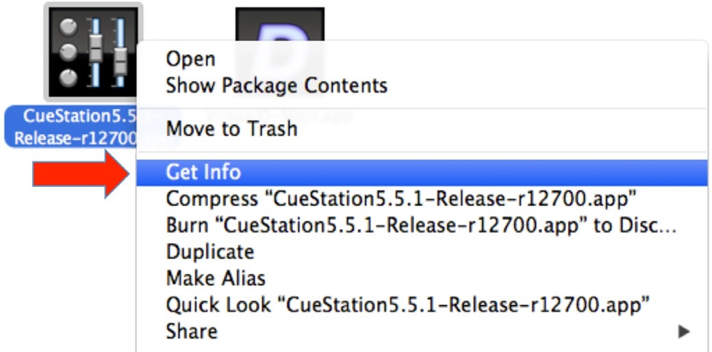
Get Info on CueStation Application
In the Information window, enable Prevent App Nap.
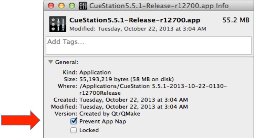
Prevent App Nap Enabled
Close the Information window.