User Guide — Compass Go
 | Welcome to Meyer Sound Lab's Compass Go User Guide. The user guide provides the information needed to create projects, along with reference materials. |
User Guide — Compass Go
Control software iPad app
Combining the key functionalities of the Compass software and the simplicity and mobility of the iPad, Compass Go makes system setup and tuning much easier and more intuitive. Simply download the latest Milan AVB or legacy AM824 AVB version from the Apple App Store, connect it to a Galileo, Galileo Callisto, or Galileo GALAXY processor on the same Wi-Fi network, and you can seamlessly and accurately optimize your sound system using the following features in the Galileo, Galileo Callisto, and Galileo GALAXY Processors:
Adjust system delay, gain, and mute
Manage U-Shaping, TruShaping, and parametric EQ filter sets
See current parameters status and any adjustments made at any control point
Recall snapshots of prior user settings
Create, edit, and store new snapshot settings in the individual processors
Move about freely without a laptop as you listen for the array coverage and quality from different seats
See the following videos to get started with Compass Go:
Compass Go compatibility
Compass Go software requires the following firmware versions:
GALAXY: v2.1.0 (All models)
Bluehorn 816: v2.1.0
Galileo/Callisto: v3.12.0
Home view
The Home View has three tabs along the bottom:
Processors
Custom Layouts
Settings
Processors view
Touch the Processors tab from the home view.
The DISCOVERED DEVICES window appears.
Select a device by touching a Discovered Device.
A green circle indicates the device is connected; a yellow rectangle indicates it is not connected. The Overview displays after selecting a new device.
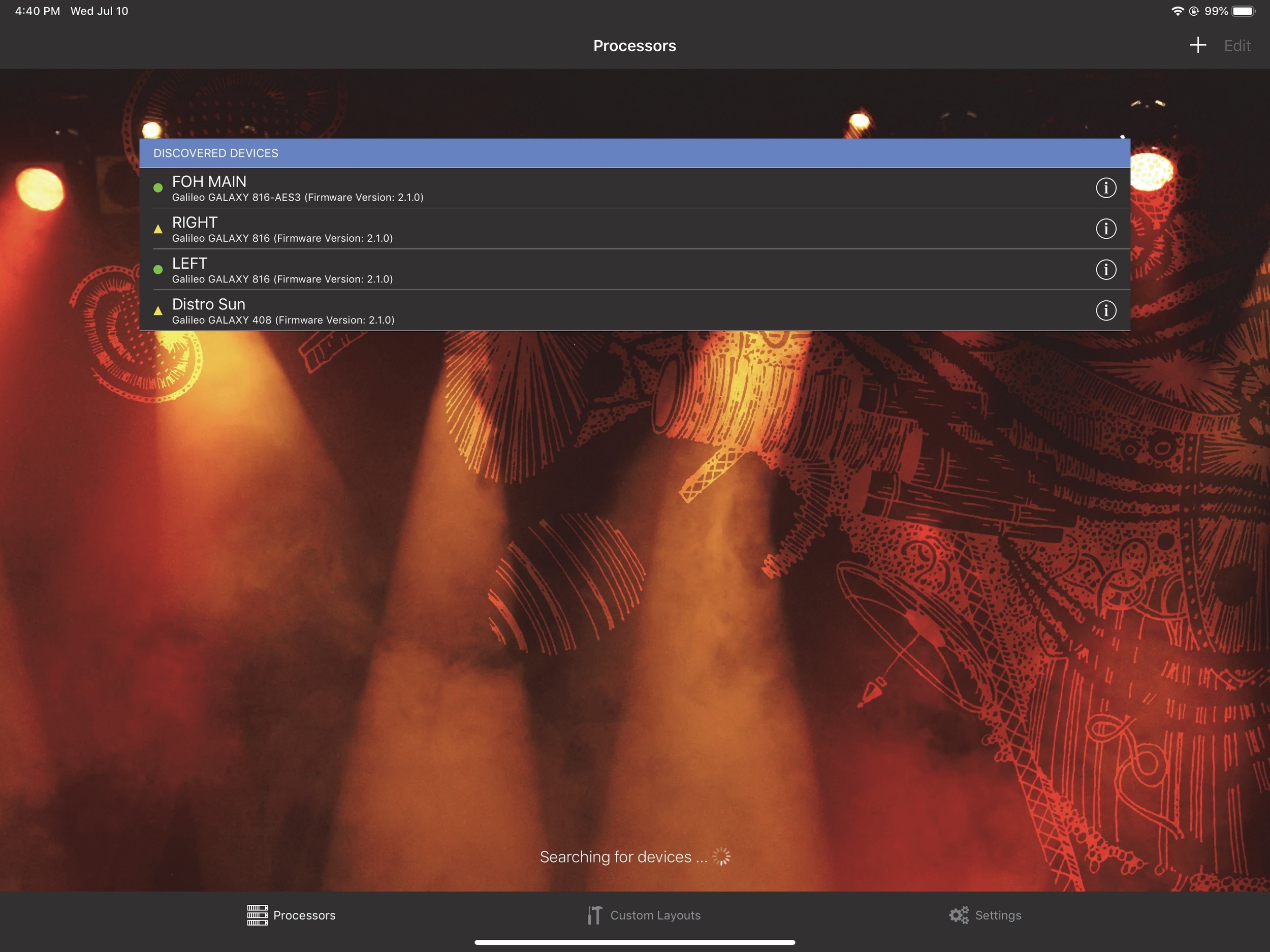
Processors View with DISCOVERED DEVICES window
Custom layouts view
Touch the Custom Layouts tab from the bottom of the home view.
The Custom Layouts View appears with the RECENT CUSTOM LAYOUTS.

Custom Layouts View with RECENT CUSTOM LAYOUTS window
Compass Go settings
To display the Compass Go Settings:
Touch the Settings tab from the bottom of the home view.
The Compass Go Settings window appears.
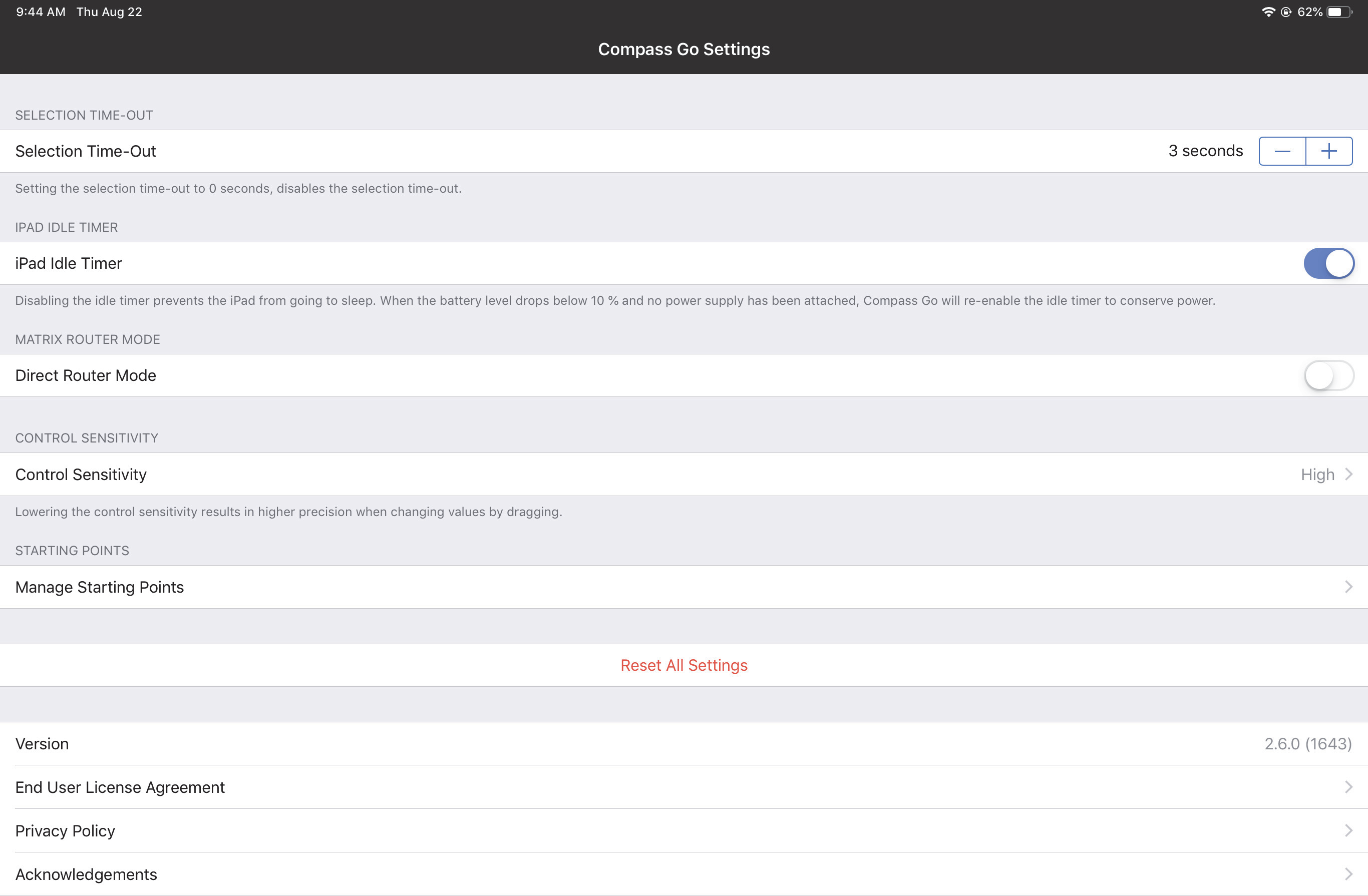
Compass Go Settings
Selection time-out
This determines how long a selection persists for graphic controls such as EQ handles.
iPad idle timer
This overrides the Auto Lock time set on the iPad when Compass Go is the active application to prevent the iPad from inadvertently turning off.
Direct router mode
The Direct Router Mode affects subsequent Router tab assignments in the Matrix View:
Slide the button to the left (inactive) position to disable direct routing.
Tap a crosspoint to toggle the gain between -∞ and 0.0. Multiple inputs can be routed to one output.
Slide the button to the right (active) position to enable direct routing.
Tap any crosspoint set to -∞ to change its value to 0.0, and set all other crosspoints in that column (out- puts) to -∞. This automatically restricts routing to one input per output.
If you previously assigned multiple inputs to the same output, and then activated Direct Router Mode, you could conceivably toggle one assignment to -∞ and still have multiple inputs routed to that output. However, by tapping any output crosspoint set to -∞, you will toggle it to 0.0, and set all other crosspoints in that column (outputs) to -∞.
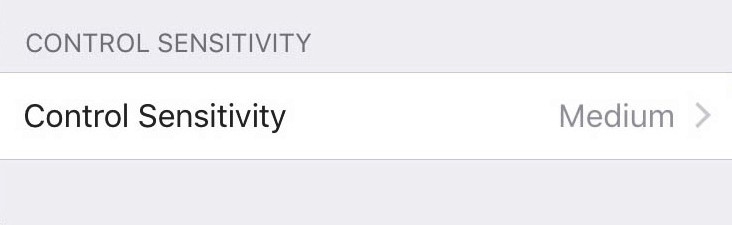
Control sensitivity
This sets the sensitivity for Compass Go’s touch controls.
Touch the current setting and choose Low, Medium, or High (default).
High sensitivity causes the fastest change in value per distance dragged.
Manage starting points
This lets you manage the list of starting points presented by this view.
Tip
See Output Delay Settings to learn how to use Starting Points to make product integration faster and easier.
Select a starting point and click the Trash icon (top-right) to delete that device from the list. The first figure below shows the first part of this list, and the second figure shows the bottom of the list.
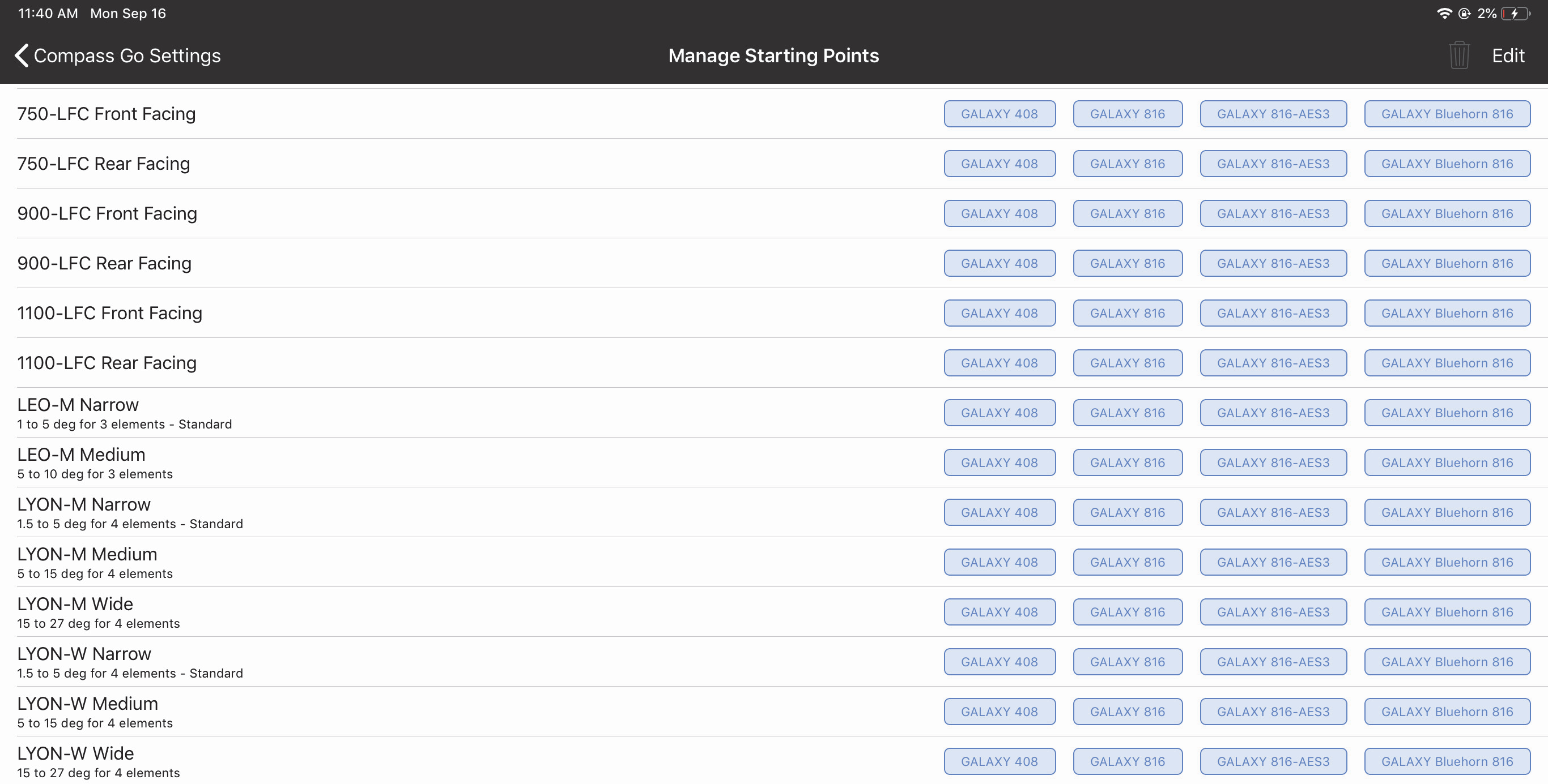
Manage Starting Points window (top)

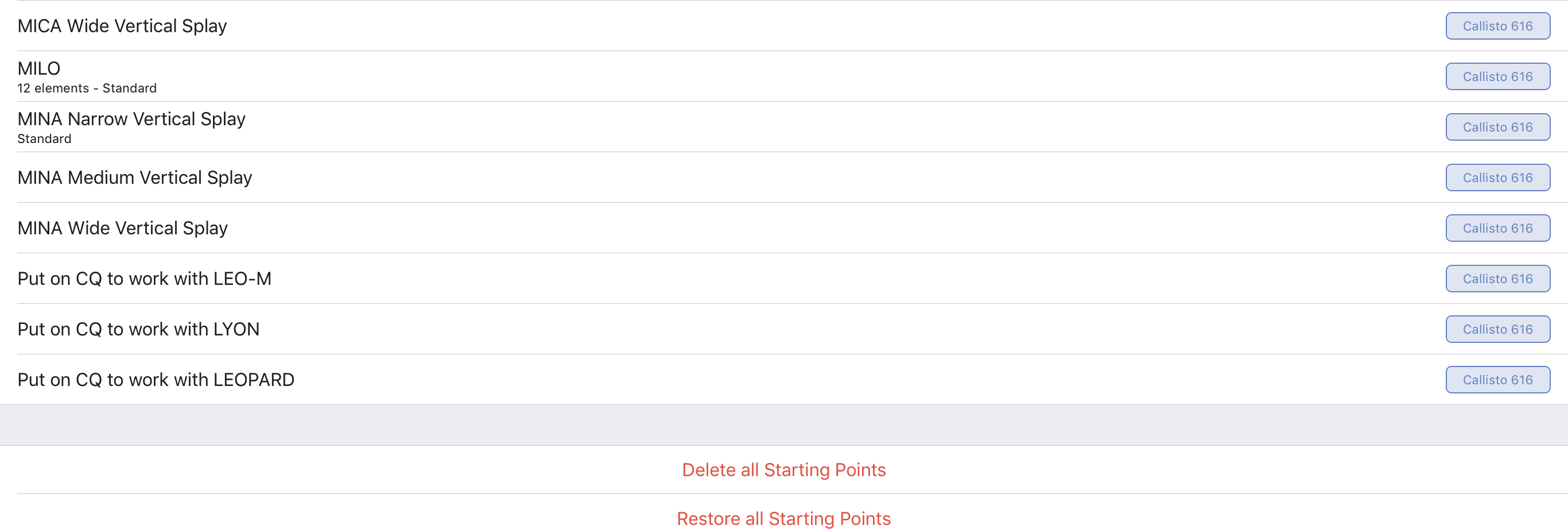
Manage Starting Points window (bottom)
Touch Delete all Starting Points to delete all Starting Points in this list.
Touch Restore all Starting Points to restore all entries originally included to the list.
Touch Edit (top-right) to rearrange the list. Touch Done when finished editing. The figure below shows an entry being dragged to a new location.
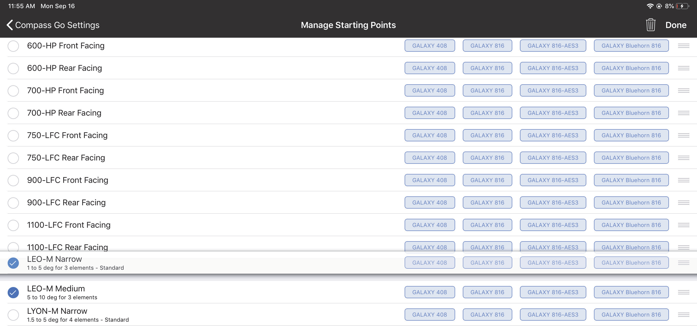
Manage Starting Points during Edit operation
Overview
Select a device from the Processors View (Device Icon is at far left) by touching a Discovered Device.
One device can be selected at a time. A green circle indicates the device is connected; a red rectangle indi- cates it is not connected.
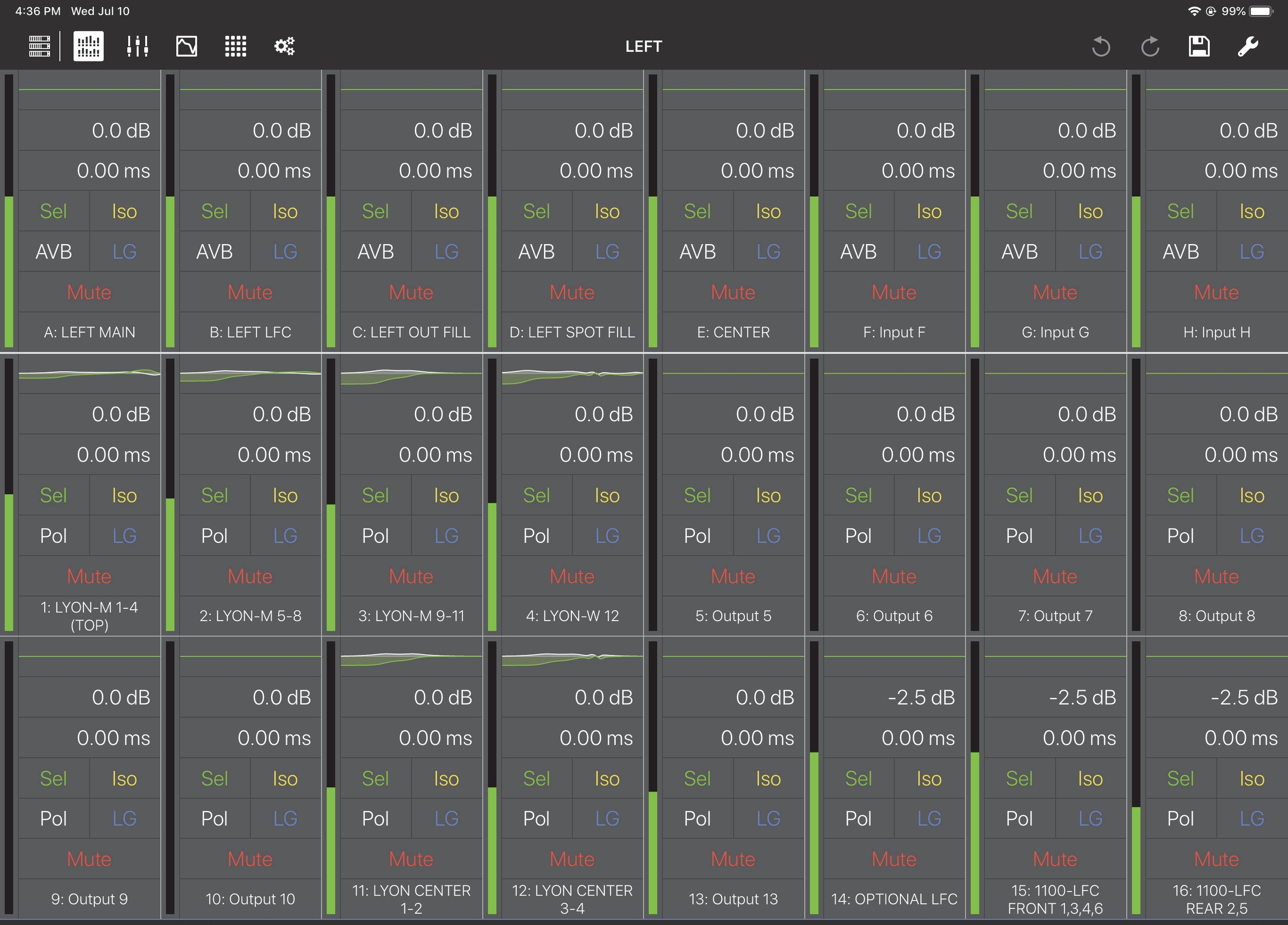
Overview
To display the Overview from any other Compass Go view, tap the Overview Icon (highlighted in the figure above) in the top menu bar.
The view is organized into one row of inputs, and two rows of outputs:
Inputs A–H (GALAXY) and Inputs A–F (Galileo and Callisto) are on the top row.
Outputs 1–8 are on the middle row.
Outputs 9–16 are on the bottom row.
Each input/output channel has a meter showing its input/output level.
Each channel control is discussed below.
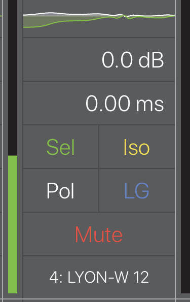
Channel detail
EQ curve
At the top of the channel, the EQ Curve is located in a small rectangle. Tapping the EQ curve displays the EQ view for that channel (see Chapter 5: EQ View).
Gain settings
Tap the gain value.
Drag up/down to increase/decrease the value. The gain can be in the range -90 dB to +10 dB.
A blue rectangle surrounds the gain value.
- OR -
Double-tap the gain value. A numeric pad opens.
A numeric pad opens.
Enter a new gain setting.
The +/- button toggles between positive and negative values.
Note that when no sign is shown, the value is interpreted as negative.
Touch Done when finished.
Delay settings
Double-tap the delay value (below the Gain field).
A numeric pad opens.
Enter a delay amount.
Tap Delay Unit to choose a unit from the following options:
milliseconds, feet, meters, frames (24 fps, 25 fps, 30 fps) samples (96 kHz).
Tap Back to return to the Delay setting numeric pad.
Tap Done when finished.
- OR -
Single-tap the delay value.
A blue rectangle surrounds it.
Touch and drag up/down to increase/decrease the delay.
The maximum delay is 2000 ms for outputs, and 500 ms for inputs.
Sel/Iso/mute status
Sel/Iso/Mute controls all work the same. Each shows its active state with a solid colored rectangle surrounding it. Touch a control to toggle its value.
Polarity (POL)
POL controls the polarity of the signal. When active, the polarity is reversed.
Link groups (LG)
Use Link Groups to edit and control multiple channels simultaneously. Assign a channel to the desired Link Group. Touch the On/Off switch to enable/disable a Link Group.
Channel name
The default channel name is derived from its input/output channel number, but can be edited. To assign a name to the channel:
Double-tap the channel name.
The Edit Channel Name dialog opens.
Use the iPad keyboard to enter a new name.
Touch Done when finished.
Overview tools
Tap the Tools icon at the top-right of the Overview to open the following dialog:

Tools options from Overview
Show SIM3 probe channel assignments
Touch and drag the button to the right to show the SIM3 Probe Channel Assignment fields on the Overview.
Touch and drag the button to the left to conceal the SIM3 Probe Channel Assignment fields from displaying on the Overview.
SIM3 settings
The current SIM3 Probe Point and Channel Settings are displayed. Touch any of them to open their assignment options.
When Show SIM3 Probe Channel Assignments is active, you can change the Console and Probe Channel assignments on the Overview by touching the C or P fields, respectively, on the desired cells.
The current SIM3 console and probe assignments determine which input and/or outputs display these assign- ment fields.
If the Processor Probe Point is set for one of the output options, a P field appears only in the output cells.
If the Console Probe Point is set for one of the output options, a C field appears only in the output cells.
If the Processor Probe Point is set for one of the input options, a P field appears only in the input cells.
If the Console Probe Point is set for one of the input options, a C field appears only in the input cells. To assign a new channel to either probe point, touch a different channel’s C or P field.
The figure below shows the Console Probe Channel set to Input C, and the Processor Probe Channel set to Output 3.
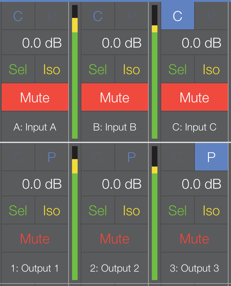
SIM3 Probe Point Assignments on the Overview
Note
The field to the left of the highlighted P for Output 3 is gray (inactive) to signify that the Console Probe Point is set to an input. The Console and Processor Probe Point types can only be changed from the Tools menu or the Settings View (see page 57).
Control sensitivity
This sets the sensitivity for Compass Go’s touch controls.
Touch the current setting and choose Low, Medium, or High (default). High sensitivity causes the fastest change in value per distance dragged.
Snapshot tool
Tap the Disk icon at the top-right of any of the active device views to open the following dialog:
Snapshot options from the Overview
Update active snapshot
Touch Update Active Snapshot to use the current settings to update the currently active Snapshot.
Create new snapshot
Touch Create New Snapshot to use the current settings to create a new Snapshot.
I/O view
To display the I/O View:
Tap the I/O Icon (highlighted in the figure below) in the top menu bar from any Compass Go view.
The I/O View appears with the Inputs or Outputs last displayed (Inputs A–H by default).
To select the eight Input or Output channels to display, do either of the following:
Touch the desired tab in the center of the top menu bar: Inputs A–H, Outputs 1–8, Outputs 9–16
- OR -
Swipe the screen left/right to scroll to the previous/next eight I/O channels. In the figure below swiping to the left displays Outputs 1–8.

I/O View displaying Outputs 9–16
Input and Output channels have the same controls except Outputs have a Pol (polarity) setting.
Sel-Iso status grid
The Sel-Iso (Select-Isolate) Status grid appears in several windows. See Sel-Iso status grid for details.
Delay
To adjust the channel delay, do either of the following:
Double-tap the delay value (at the top of the channel). A numeric pad opens.
Enter a delay amount.
Tap Delay Unit to choose a unit from the following options:
milliseconds, feet, meters, frames (24 fps, 25 fps, 30 fps), samples (96 kHz).
Tap Back to return to the Delay setting numeric pad.
Tap Done when finished.
Tap Back to return to the Delay setting numeric pad.
Tap Done when finished.
- OR -
Single-tap the delay value.
An orange rectangle surrounds it.
Touch and drag left/right to increase/decrease the delay.
The maximum delay is 2000 ms for outputs, and 500 ms for inputs.
Sel/Iso/mute/pol
See Sel/Iso/mute/pol
Link groups
Link Groups let you control multiple Inputs or Outputs simultaneously with one control. There are four Input Link Groups, and eight Output Link Groups.
Tap Link Group Name to enter a name for the Input or Output Link Group.
Fader
Tap and drag it to a new position.
- OR -
Double-tap the numeric field above the fader to open a numeric pad.
Enter a new value (maximum = +10, minimum = -90).
The +/- button toggles between positive and negative values.
Note that when no sign is shown, the value is interpreted as negative.
Tap Done when finished.
I/O view tools
Tap the Tools icon at the top-right of the I/O View to open the following dialog:
Tools option from I/O View
Control sensitivity
This sets the sensitivity for Compass Go’s touch controls.
Touch the current setting and choose Low, Medium, or High (default).
High sensitivity causes the fastest change in value per distance dragged.
EQ view
Tap the EQ Icon (highlighted in the figure below) in the top menu bar from any Compass Go view.
- OR -
From the Overview or I/O views, double-tap the EQ curve at the top of the channel.
The EQ View appears with the Channel Settings tab selected unless the Parametric, U-Shaping, or All Pass tab was last selected for that channel.
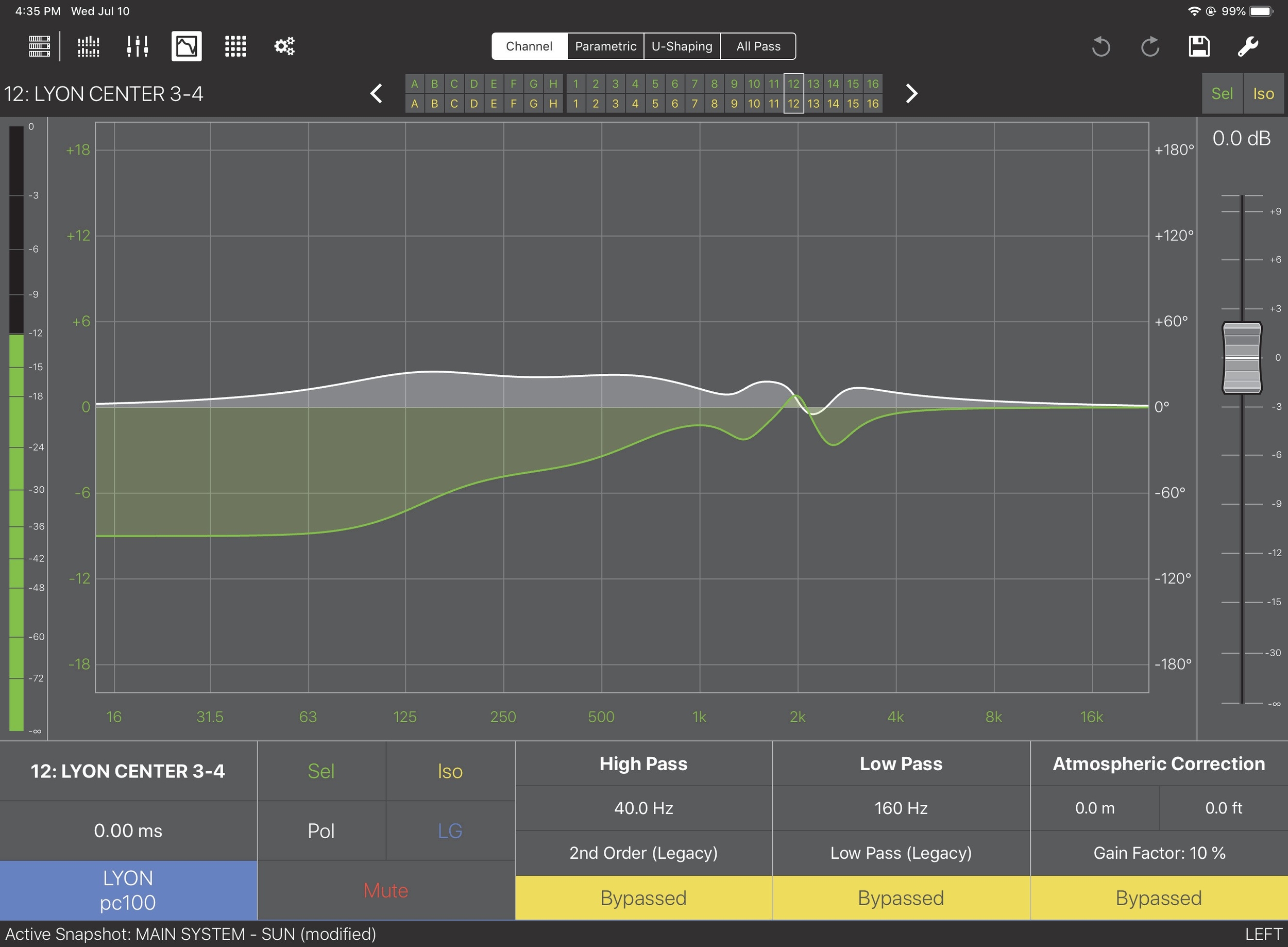
EQ View with Channel Settings controls
Channel Settings, Parametric, U-Shaping, and All Pass tabs each have their own meter, fader, and share these screen entities:
Channel Settings, Parametric, U-Shaping, and All Pass tabs along the top
Tap the tab to activate the desired controls. Each tab is discussed in detail below.
Sel-Iso Status Grid
This grid shows any selected or isolated input/output channels. The status of any channel can be toggled directly from the grid. See below for details.
Sel-Iso status grid
The Sel-Iso (Select-Isolate) Status Grid is comprised of two rows: channel selection is indicated on top, channel isolation on bottom.
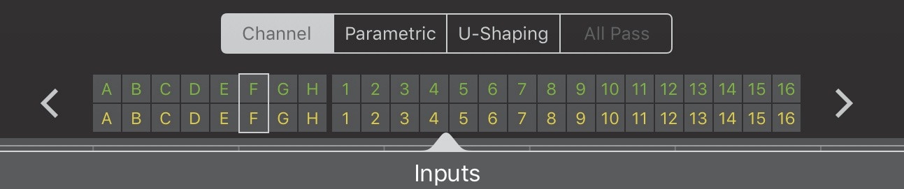
Sel-Iso Status Grid
In the figure above, Input F is selected and isolated.
The rectangle enclosing Input F shows the currently selected I/O channel on the EQ View. Touch the left or right arrows at each end of the grid to move the selection rectangle to the previous or next I/O channel, respectively. This is an easy way to quickly peruse I/O channels.
Touch within the grid.
The grid expands as shown in the figure below.
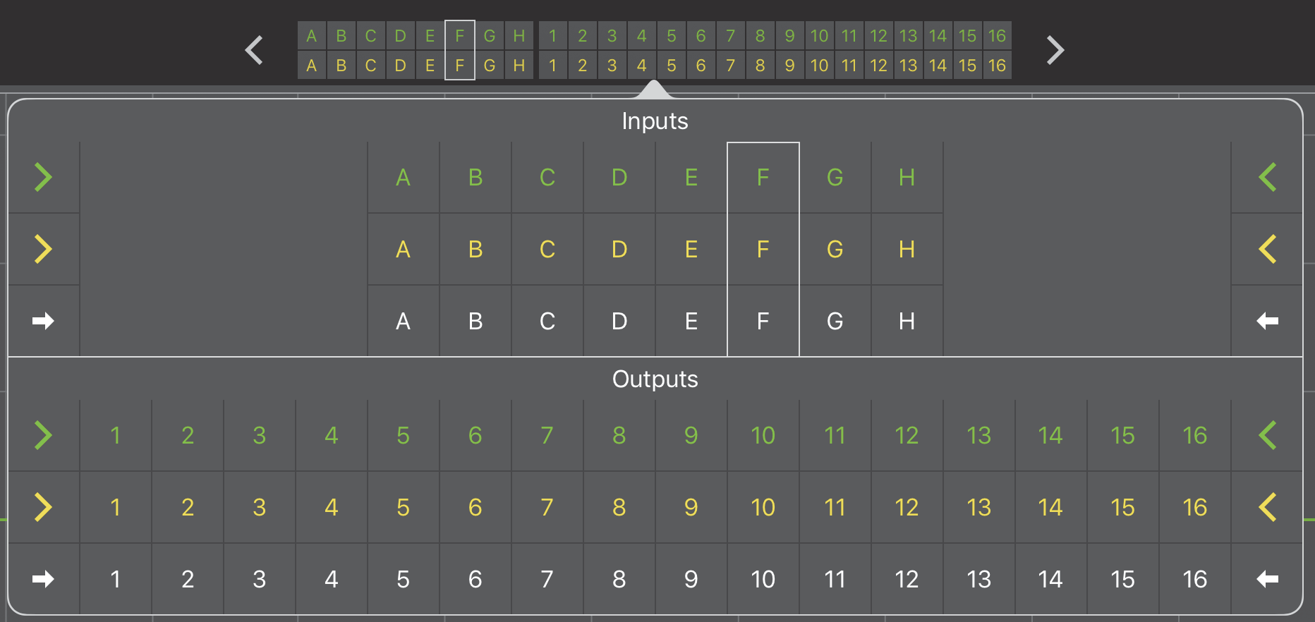
Sel-Iso Grid expanded
Tap an arrow pointing into the grid to select all values.
Tapping either yellow arrow pointing into the Iso Inputs selects them all.
Tap an arrow pointing out of the grid to deselect all values.
Tapping either green arrow pointing out of the Sel Inputs (or Outputs) deselects them all. If one or more channel is selected or isolated, the arrows point out.
Tap an individual I/O channel cell to toggle its value.
Fader
Tap and drag it to a new position.
- OR -
Double-tap the numeric field above the fader to open a numeric pad.
Enter a new value (maximum = +10, minimum = -90).
The +/- button toggles between positive and negative values.
Note that when no sign is shown, the value is interpreted as negative.
Tap Done when finished.
Channel settings tab
The Channel Settings tab has these additional controls:
High and Low Pass filters
Atmospheric Correction
Output Delay Settings
Product Integration
Sel/Iso/Mute/Pol controls
LG (Link Group) controls
Bypassed/Enabled
Tap to toggle the Enabled/Bypassed state of the High or Low Pass filter. A solid yellow rectangle surrounds Bypassed.
High and low pass filters (outputs only)
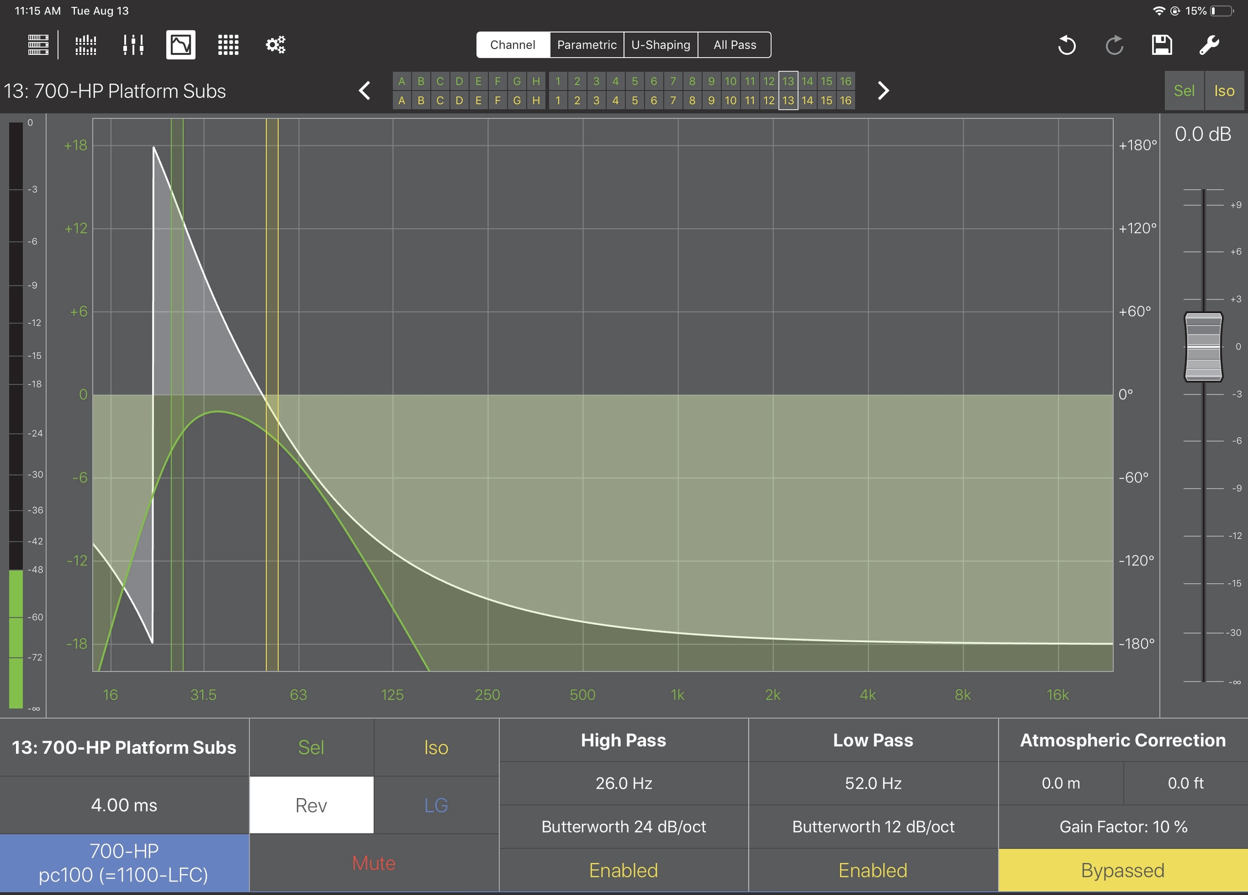
High and Low Pass Filter
Frequency
Touch the yellow (Low Pass) or green (High Pass) filter line or the High/Low Pass frequency value.
When selected, a blue rectangle surrounds the frequency value. The green or yellow line highlights to show the selected filter for editing. This state persists for 3 seconds, then extinguishes.
While the filter is selected for editing, do either of the following:
Touch the green or yellow line and drag to a new position; the frequency field updates while the line is moved.
- OR -
Touch within the blue highlighted rectangle and drag up/down to increase/decrease the frequency values; the corresponding line moves as its frequency value changes.
Filter type
Double-tap the filter type beneath the frequency value.
The High or Low Pass Type dialog opens. The currently selected filter has a checkmark next to it.
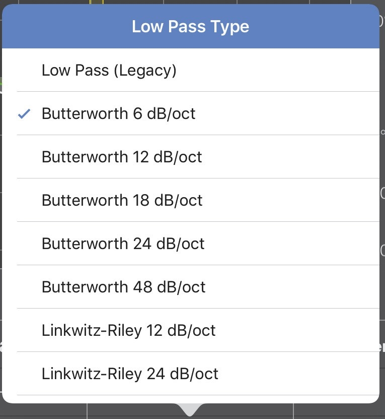
Low Pass Filter Type dialog
Touch the desired filter type.
Atmospheric correction (outputs only)
Distance
If Atmospheric Correction is Enabled, single tap either distance unit value. A blue rectangle surrounds the distance value.
Drag up/down to increase/decrease the value.
- OR -
Double-tap the distance value.
A numeric pad opens even if Atmospheric Correction is Bypassed.
Enter a value and tap Done when finished. The maximum distance is 150 m.
Gain factor
Double-tap Gain Factor.
Choose a value in the range 10 –100% in 10% increments.
Tap outside the dialog to close it.
Enabled/Bypassed
Tap to toggle the Enabled/Bypassed state. A yellow solid rectangle surrounds Bypassed.
Output Delay Settings
Double-tap the delay value (below the channel name on the lower left). A numeric pad opens.
Enter a delay amount.
Tap Delay Unit to choose a unit from the following options:
milliseconds, feet, meters, frames (24 fps, 25 fps, 30 fps) samples (96 kHz).
Tap Back to return to the Delay setting numeric pad.
Tap Done when finished.
- OR -
Single-tap the delay value.
A blue rectangle surrounds it.
Touch and drag up/down to increase/decrease the delay.
The maximum delay is 2000 ms for outputs, and 500 ms for inputs.
Product integration
The Product Integration is on the lower left of the EQ View. It consists of Product, Delay Integration, and EQ Integration fields.
Product
First select the Product you would like to integrate:
Tap the current product name to open the Product Integration menu.
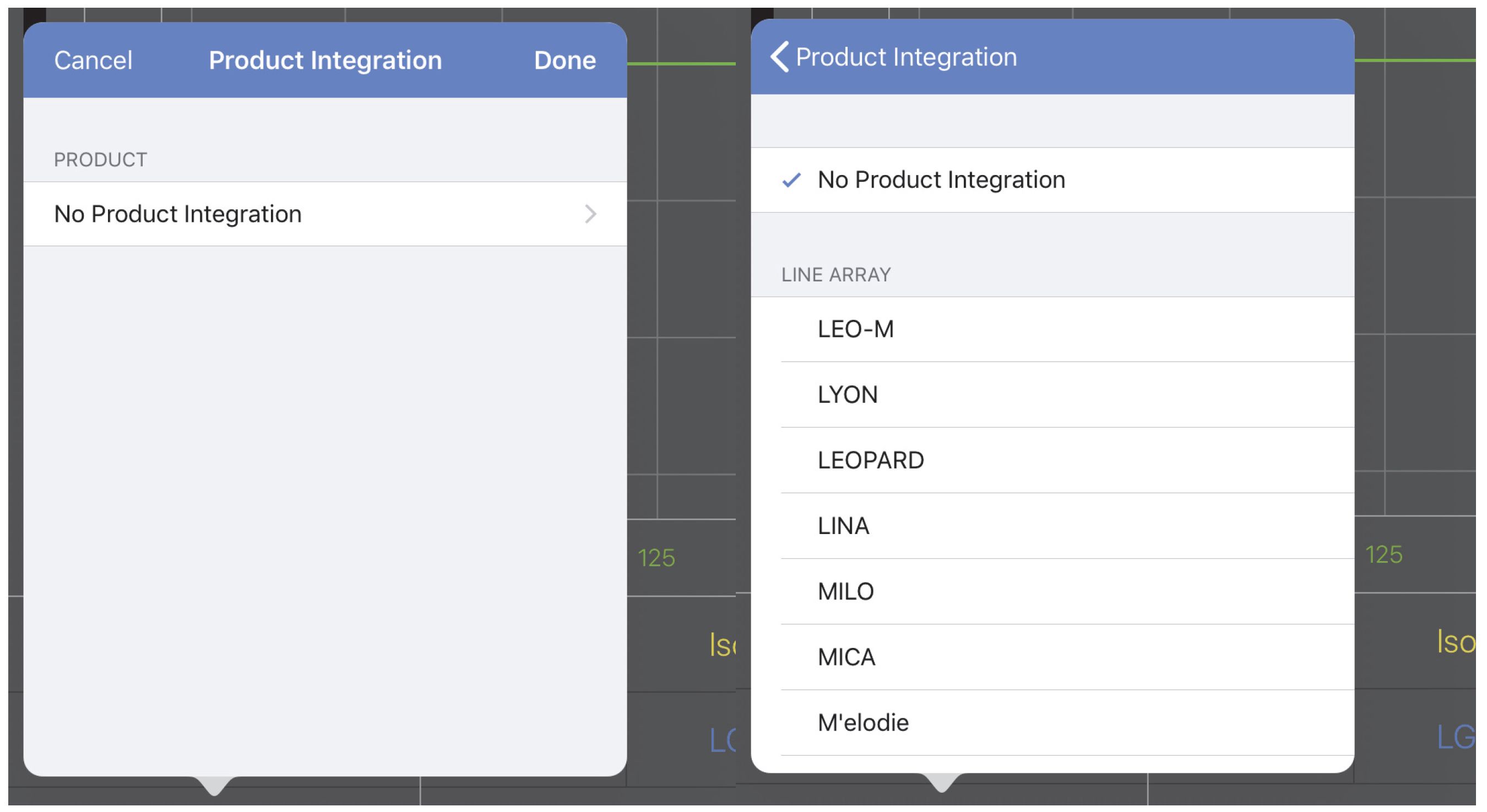
Product Integration menus
Tap the current product name to open the menu to select a new product.
Select the lowest possible pc (phase curve) value for all channels connected to a Meyer Sound product.
All channels should have the same pc value.
The Delay Integration standard applies corrective filters to match the acoustic characteristics between Meyer Sound product families without introducing excessive shifts in phase that degrade intelligibility and signal clarity. Delay integration is also a quick alignment tool to ensure coherent summation when combining different loudspeaker elements.
Using Delay Integration to the lowest GALAXY phase curve setting possible for all loudspeakers lets your loudspeaker or loudspeaker system perform to the best possible phase curve, providing uniform and integrated system behavior without audio artifacts when transitioning between sources.
Delay integration for subwoofers provides a more controlled response that makes it easier to integrate with both current and past Meyer Sound loudspeaker systems. Matching the GALAXY pc settings for subwoofer products also provides an easier integration between different subwoofer products by unifying their sonic signature, making them easier to align.
Select the product followed by the desired pc frequency: 55-70, 100, or 125 (Hz). Not all products have every option available (except 125 Hz). Choose the lowest pc available for all of the loudspeaker models in a system.
Below the Delay setting, tap No Delay Integration (if never set) or the solid blue rectangle with the Meyer powered loudspeaker listed within it. All compatible loudspeakers appear in this list.
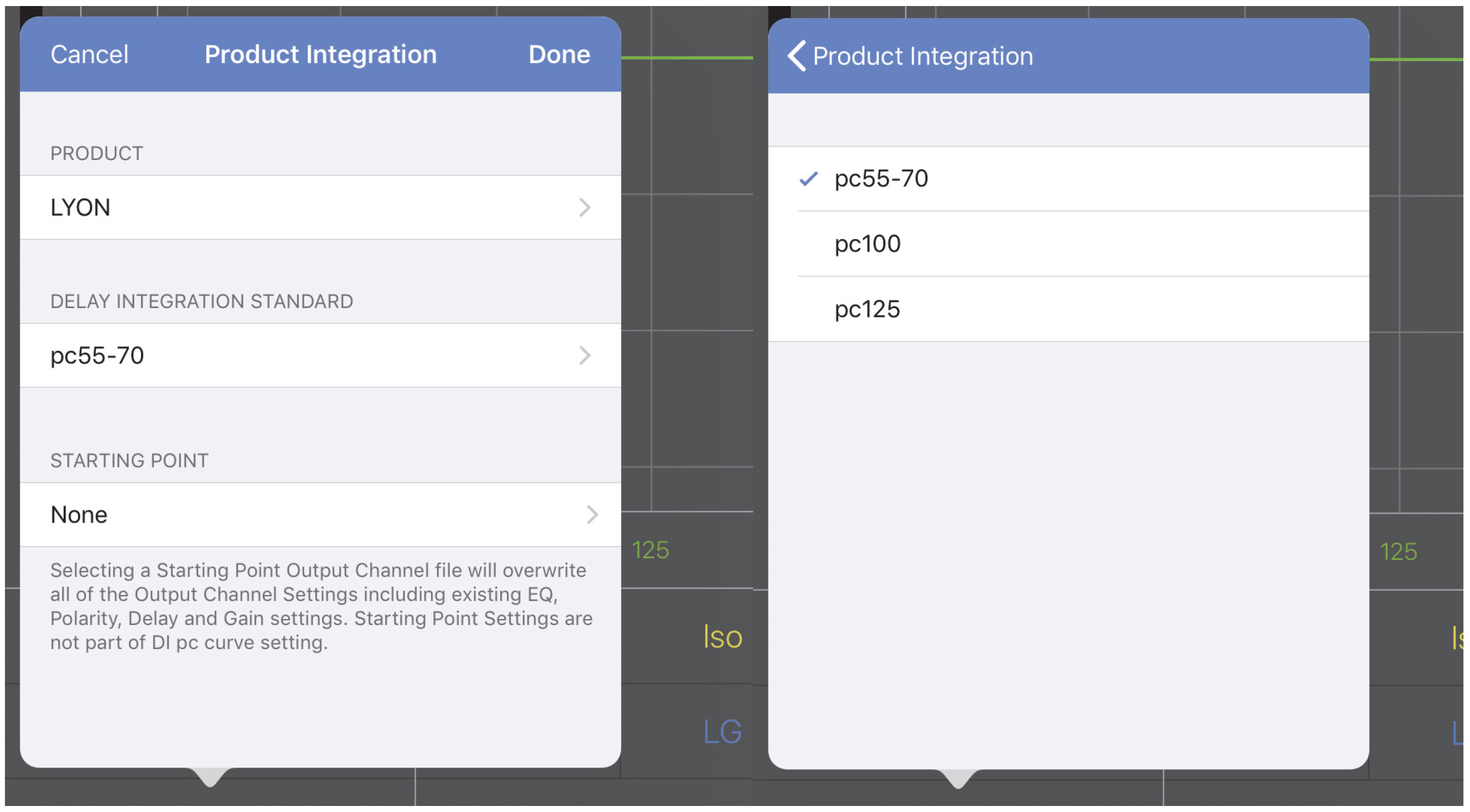
Selecting Delay Integration standard
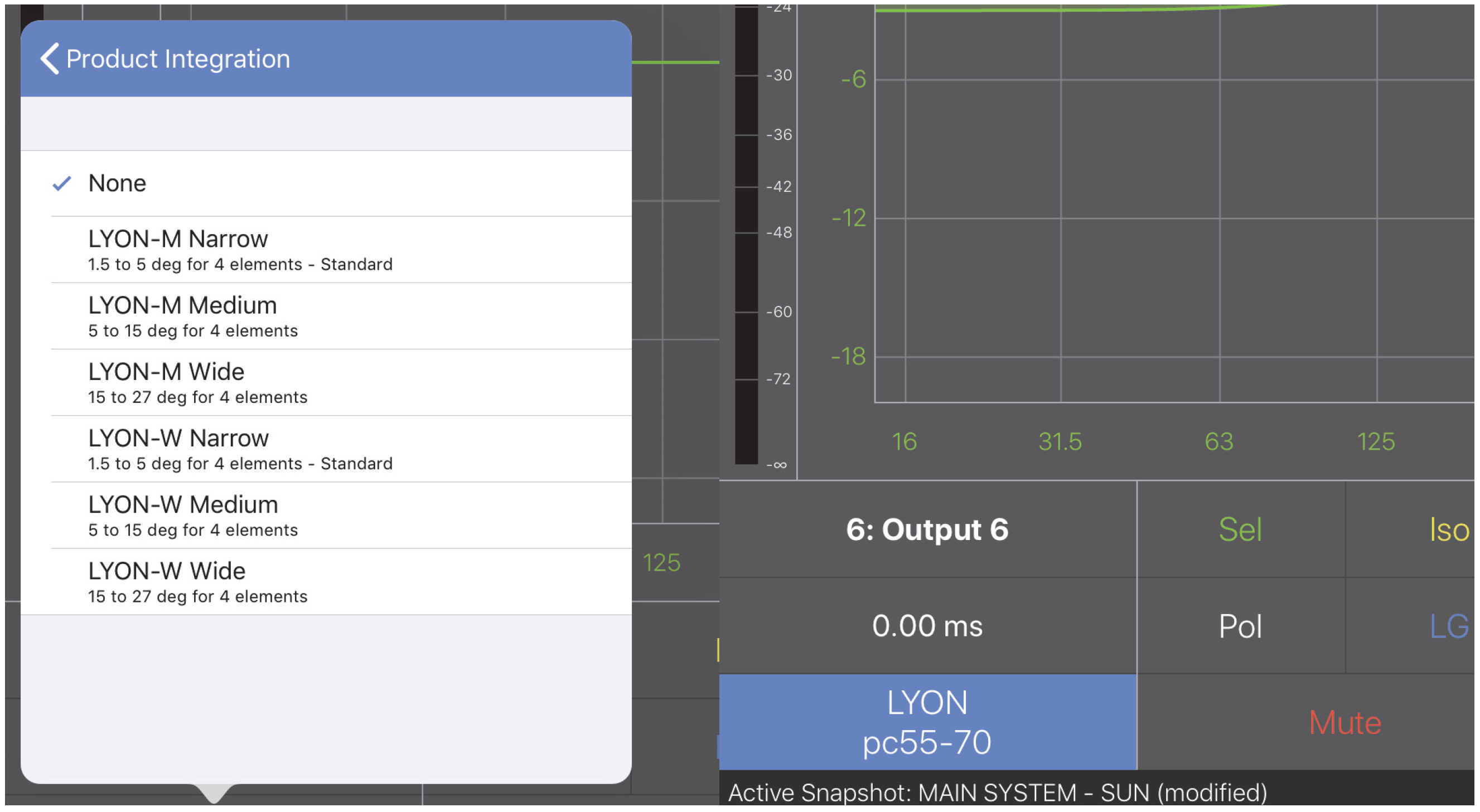
Starting Points menu (left) and completed field (right)
Sel/Iso/mute/pol
Tap Sel, Iso, Mute controls to toggle their values. A rectangular box surrounds an active value.
Tap Pol to reverse the Polarity (outputs only).
Pol is normal; Rev is reversed.
Link groups (LG)
Use Link Groups to edit and control multiple channels simultaneously. Assign a channel to the desired Link Group. Touch the On/Off switch to enable/disable a Link Group.
Inputs have four Link Groups, outputs have eight.
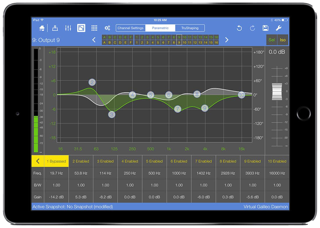
Parametric controls
To display the Parametric controls from the EQ View, tap the Parametric tab in the center of the top menu bar.
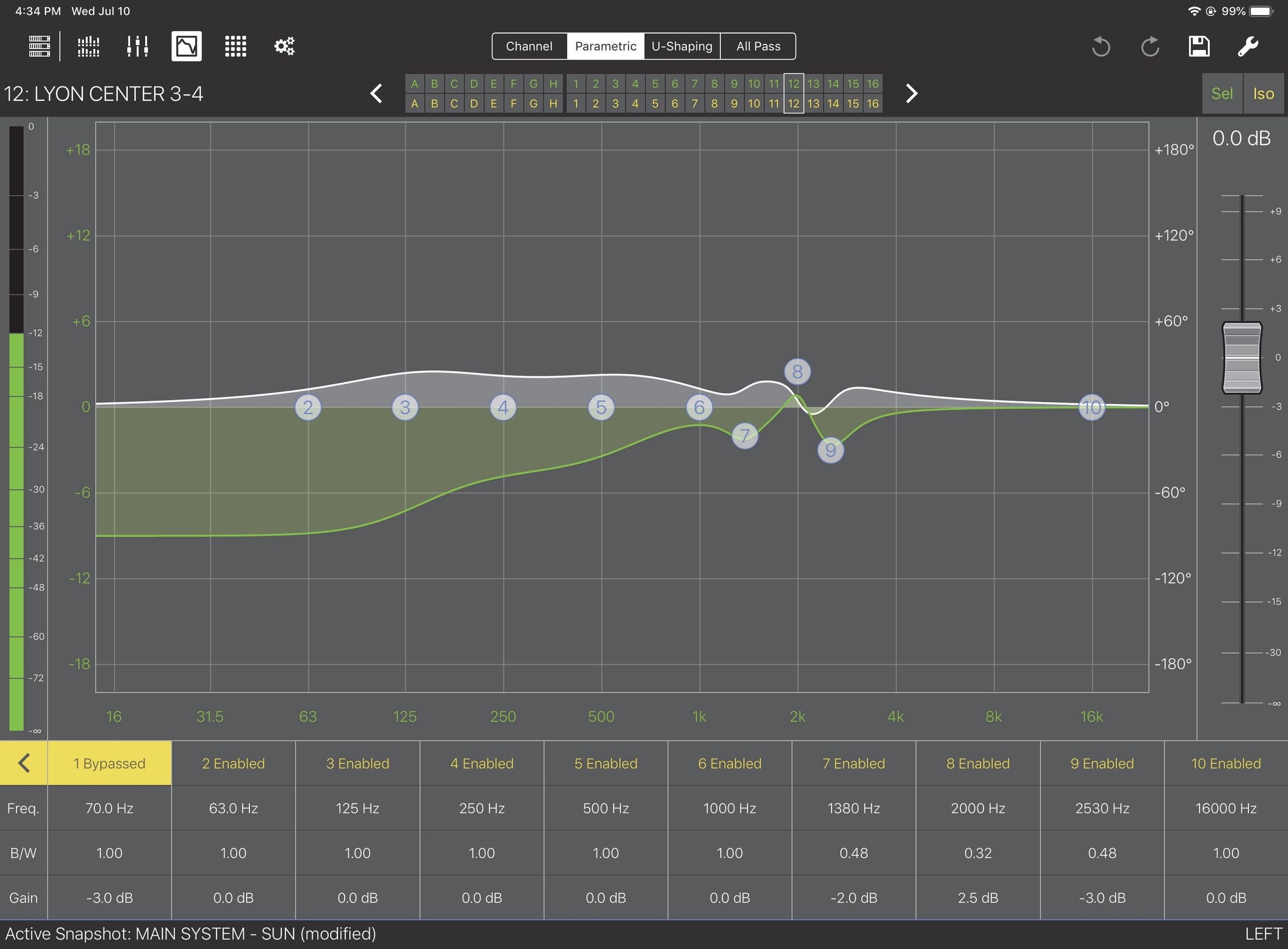
EQ View with Parametric controls
Touch a filter’s Freq., B/W, or Gain value.
- OR -
Touch a filter’s number in the graph.
In both cases, a blue rectangle surrounds the channel’s settings and the filter number highlights in blue on the graph. The selection persists for 3 seconds before extinguishing.
With a filter selected, you can adjust its settings by doing either of the following:
Touch the filter number and drag up/down to alter the gain, or drag left/right to adjust frequency.
Tip
Drag in both directions to adjust frequency and gain at once.
Use three fingers to drag to change the gain but keep the frequency constant.
- OR -
Double-tap Freq., B/W, or Gain.
A numeric pad opens so you can enter values directly.
Enter a new value.
The +/- button toggles between positive and negative values.
Note that when no sign is shown, the value is interpreted as negative.
Tap Done when finished.
Note
Touching and dragging within a selected channel’s settings operates the same as if you touched and dragged the filter number. Freq. and Gain can be adjusted in this manner but not B/ W. Use a two-finger pinch/spread gesture to change B/W.
Each filter can be individually enabled or bypassed.
Touch Enabled or Bypassed at the top of the filter’s settings to toggle its state.
Touch the yellow arrow at the far left of the window.
If one or more filters is Bypassed, the arrow faces left and will set all filters to Enabled when touched. In the figure below, touching the left-facing arrow sets all filters to Enabled and the arrow will point to the right.
Bypassed/Enabled control to toggle all channels
U-shaping controls
To display the U-Shaping controls from the EQ View, tap the U-Shaping tab in the center of the top menu bar.
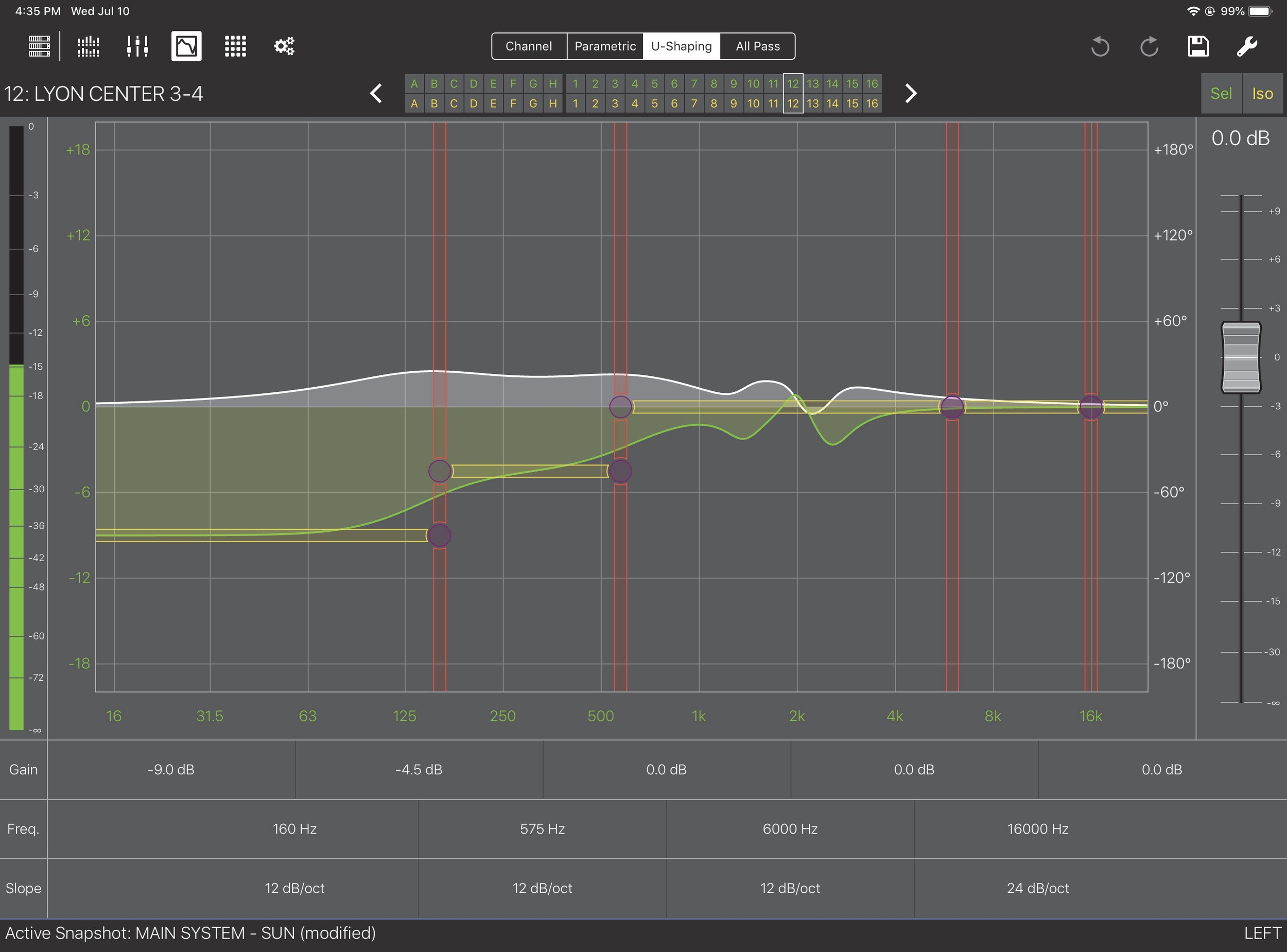
EQ View with U-Shaping controls
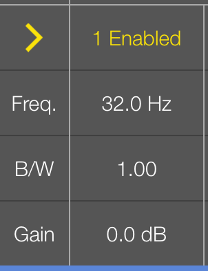
Touch a vertical red line to select a filter’s frequency.
The line highlights in red and the Freq. setting has a red outline.
In the figure above, Freq. is selected for the highest filter.
Touch a horizontal yellow line to select gain.
The line highlights in yellow and the Gain setting has a yellow outline.
The selected state persists for 3 seconds before extinguishing.
To adjust a selected filter:
Drag a red selected Freq. line left/right to decrease/increase the value.
Dragging within the Freq. value accomplishes the same function.
Drag a yellow selected Gain line up/down to increase/decrease the value.
Dragging within the Gain value accomplishes the same function.
Double-tap the Slope value to select a value for the filter (see options below).
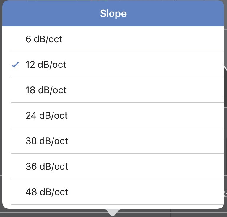
Slope options for U-Shaping filters
Note
The first two breakpoints include the Slope options shown above; the next two do not include 48 dB/oct.
All pass filter controls
To display the All Pass controls from the EQ View, tap the All Pass tab at the right of the top menu bar.
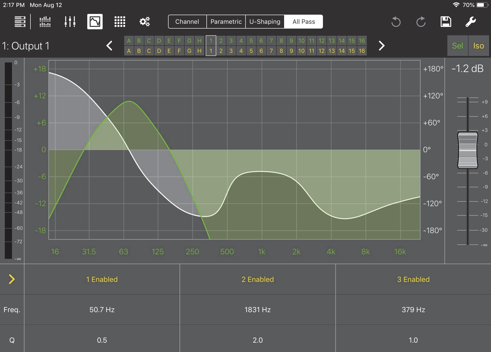
EQ View with All Pass controls
Touch and drag up/down in the Freq. field to increase/decrease the frequency.
Double tap the Q field to bring up a numeric pad in which you can enter the Q value.
In both cases, a blue rectangle surrounds the channel’s settings and the filter number highlights in blue on the graph. The selection persists for 3 seconds before extinguishing.
Each filter can be individually enabled or bypassed.
Touch Enabled or Bypassed at the top of the filter’s settings to toggle its state. To set all filters to the same state:
Touch the yellow arrow at the far left of the window.
In the figure above, touching the right-facing arrow sets all filters to Bypassed.
If one or more filters is Bypassed, the arrow faces left and will set all filters to Enabled when touched.
EQ view tools
The content of the EQ View Tools menu depends on the device and whether an input or output is currently selected. The EQ View Tools menu shown below is from a GALAXY output, which contains all relevant controls.
Tap the Tools icon at the top-right of the EQ View to open the following dialog:

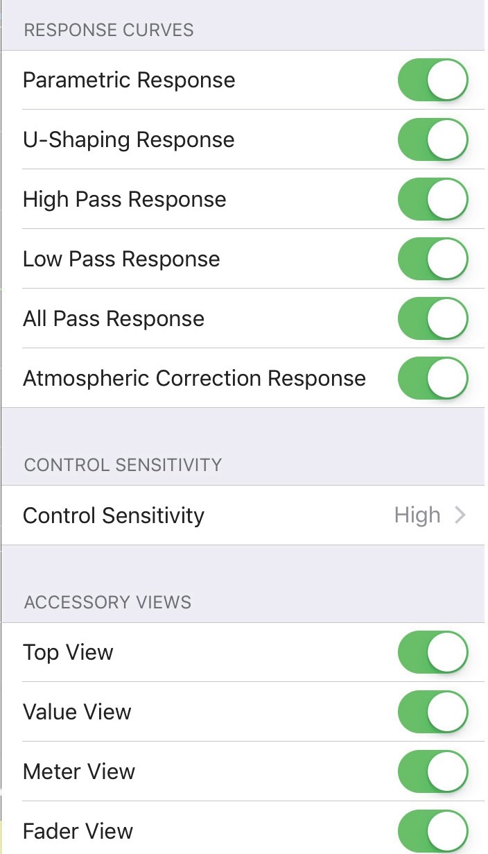
EQ View Tools options for a GALAXY output: Upper controls (left), lower controls (right)
Enabled filters
Swipe the buttons to the right (active) to enable the desired filter types. If a filter is enabled and has settings applied, you can disable it but still retain its values for later use; just re-enable the filter.
Note
Some devices do not include all of these filter options.
Starting points
Touch Choose Starting Point to set a new Starting Point. This may overwrite any current parameters already set.
Note
Only the Callisto 616 and GALAXY outputs offer this option.
The following Meyer Sound loudspeaker options can be used as a Starting Point:
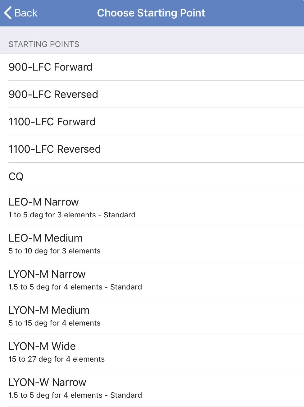
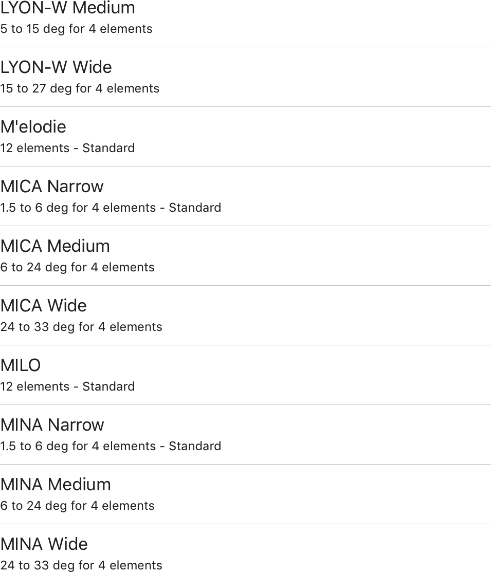
Choosing a new Starting Point: Top of menu (left), bottom of menu (right)
Reset EQ
Touch Reset Parametric EQ, Reset U-Shaping EQ, Reset High Pass, Reset Low Pass, or Reset All Pass, to reset that filter to flat (0 gain at all bands) and all other filter parameters (i.e., bandwidth, frequency, slope, etc.) to their default values. Touch Reset All EQ to reset all filters to their default values at once.
Note
Some devices do not include all of these reset options.
Response curves
Swipe any of the Response buttons to the right (active) position to enable display for those curves in other windows. This setting is channel-specific so you can show any combination of these curves for each input and output.
Control sensitivity
This sets the sensitivity for Compass Go’s touch controls.
Touch the current setting and choose Low, Medium, or High (default).
High sensitivity causes the fastest change in value per distance dragged.
Accessory views
Swipe the Top View, Value View, Meter View, and/or Fader View buttons to the right (active) position to show those entities in the EQ View window. You can conserve screen area by swiping them to the left when they are not essential to your current task.
SIM3 trim (Galileo and Callisto only)
Each output channel can be enabled/disabled in the SIM3 section of the device settings. When enabled, the SIM3 Trim for each output can be adjusted between -12 dB and +6 dB.
Matrix view
To display the Matrix View, tap the Matrix Icon (highlighted in the figure below) in the top menu bar from any Compass Go view.
The Matrix View has three tabs: Gain Mode, Router Mode, and Delay Mode. Touch a tab to change the display. When visiting other views, the last mode displayed is used when you reselect the Matrix View. Gain Mode is selected in the figure below.
Each matrix contains the following entries:
8 processed inputs A–H
24 unprocessed AVB inputs 9–32
16 processed outputs 1–16
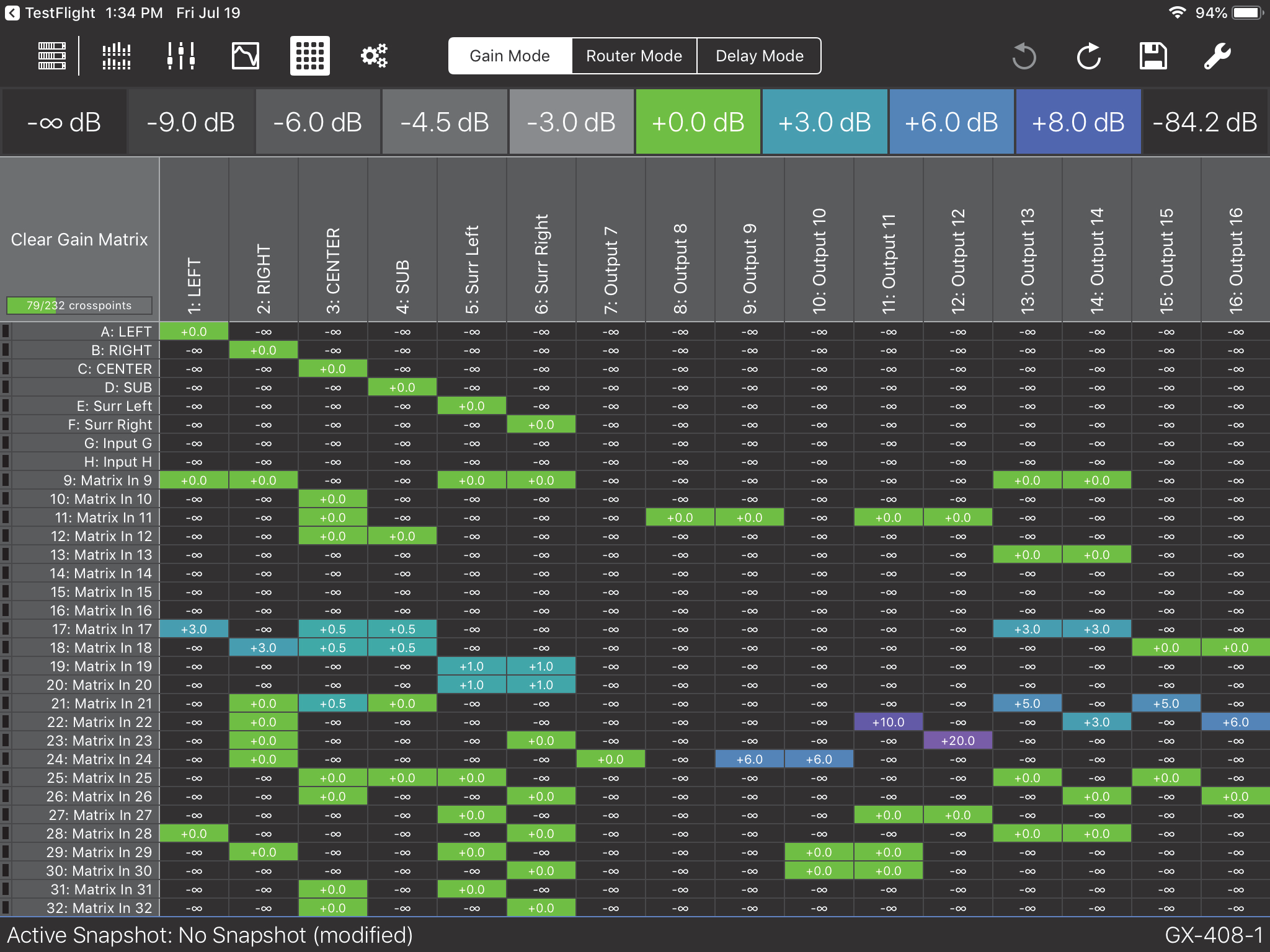
Gain mode
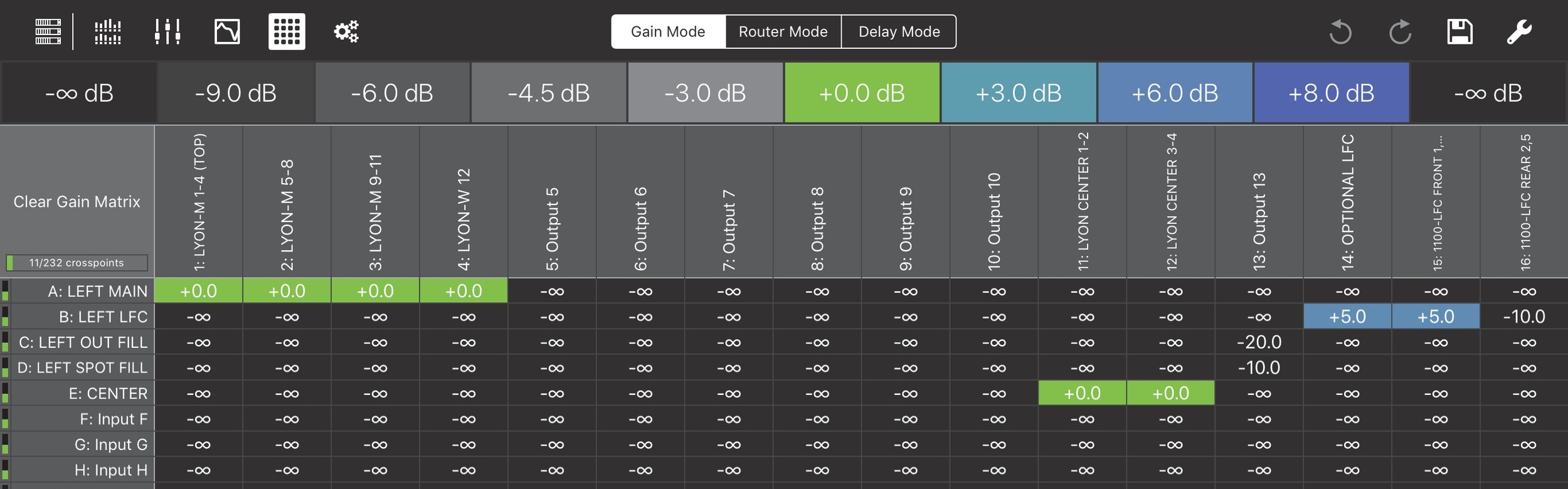
Matrix View in Gain Mode
Touch the cell to select it.
A white rectangle encloses the cell. The selection persists for 3 seconds before extinguishing.
Touch a dB value from the top list.
The cell updates with that value.
Touch multiple cells to select them.
A white rectangle encloses each selected cell. The selection persists for 3 seconds before extinguishing.
Touch a dB value from the top list.
The cells update with that value.
To select an entire Input or Output, touch its label on the left or top, respectively.
To select all cells, touch Select All at the top left.
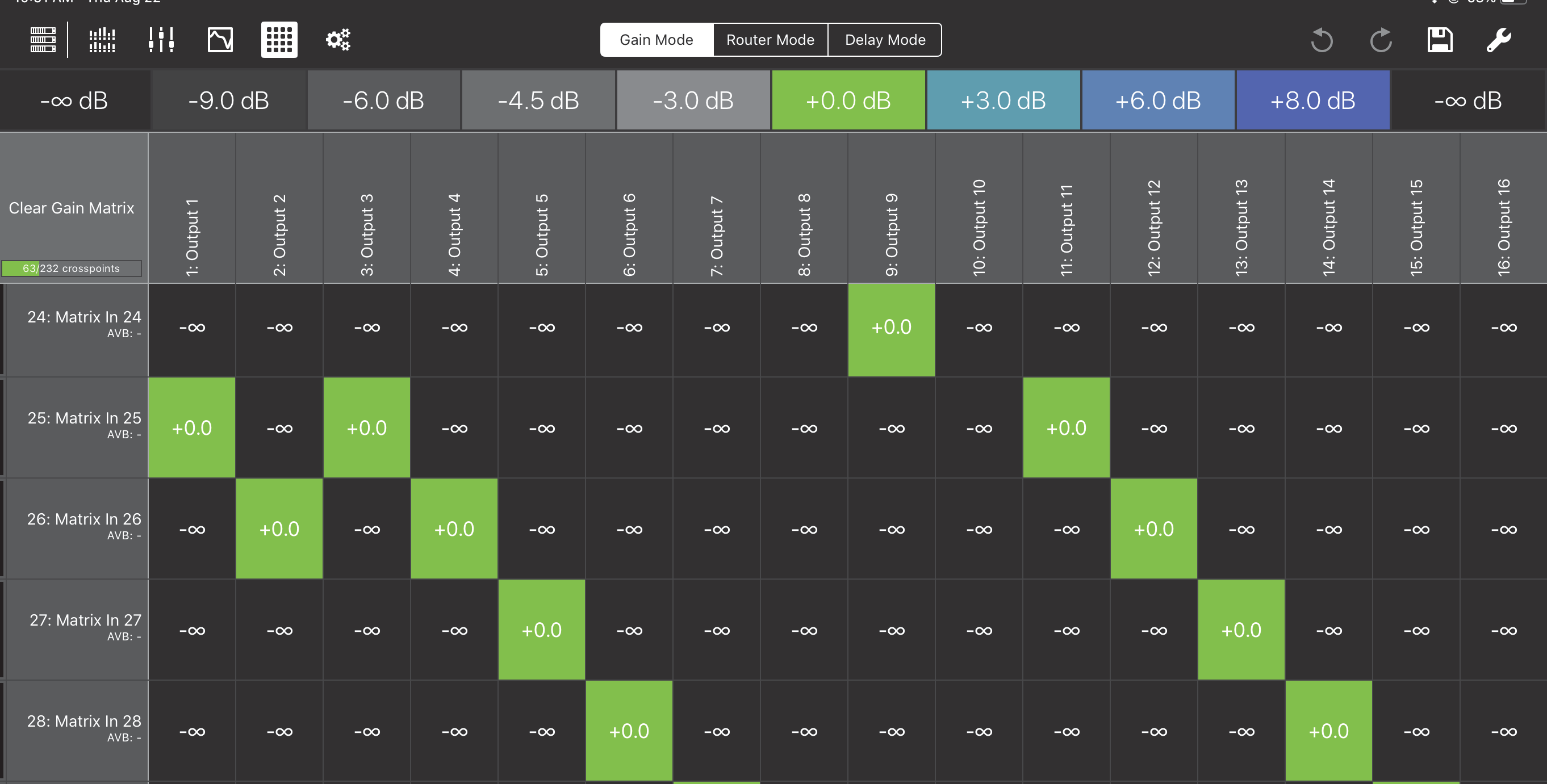
Router mode

Matrix View in Router Mode
Touch a cell marked -∞ to set it to 0 dB.
Touch a cell marked with any dB value other than -∞ to set it to -∞.
Double-tap the cell.
A numeric pad opens.
Enter a new value.
Gain settings can vary from -90 to 20 dB.
The +/- button toggles between positive and negative values.
Note that when no sign is shown, the value is interpreted as negative.
Touch Done when finished.
Touch an Input or Output label.
Touch Clear Gain Matrix
Note
See ??? to learn about additional assignment options
Delay mode
Delay Mode can set a delay between Inputs and Outputs.
Matrix View in Delay Mode
To select one or more cells for editing, do one of the following:
Touch each cell you wish to select.
Touch an Input or Output label to select the entire row or column, respectively.
Touch Select All at the top left to select all cells.
A white rectangle encloses each selected cell. The selection persists for 3 seconds before extinguishing. While cells are selected, do either of the following:
Drag up/down to increase/decrease the delay.
- OR -
Double-tap a selected cell. A numeric pad opens.
Enter a new delay value.
Touch Done when finished.
All selected cells update with their new values.
Expanded matrix inputs
The figures below show the expanded Matrix inputs available to the Router, Gain, and Delay Matrices. You can zoom in/out with a two-finger spread/pinch gesture.
Expanded Matrix Inputs
Expanded Matrix zoomed in
Matrix view tools
Tap the Tools icon at the top-right of the Matrix View to open the following dialog:
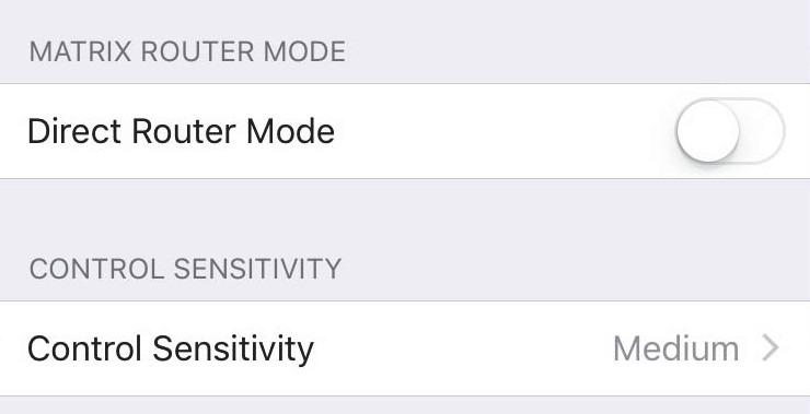
Tools options from Matrix View
Direct router mode
The Direct Router Mode affects subsequent Router tab assignments in the Matrix View:
Slide the button to the left (inactive) position to disable direct routing.
Tap a crosspoint to toggle the gain between -∞ and 0.0. Multiple inputs can be routed to one output.
Slide the button to the right (active) position to enable direct routing.
Tap any crosspoint set to -∞ to change its value to 0.0, and set all other crosspoints in that column (out- puts) to -∞. This automatically restricts routing to one input per output.
If you previously assigned multiple inputs to the same output, and then activated Direct Router Mode, you could conceivably toggle one assignment to -∞ and still have multiple inputs routed to that output. However, by tapping any output crosspoint set to -∞, you will toggle it to 0.0, and set all other crosspoints in that column (outputs) to -∞.
Control sensitivity
This sets the sensitivity for Compass Go’s touch controls.
Touch the current setting and choose Low, Medium, or High (default).
High sensitivity causes the fastest change in value per distance dragged.
Settings view
Select a device from the Devices View.
Tap the Settings icon (highlighted in the top-left menu bar in the figure below). The Snapshot Settings are shown below.

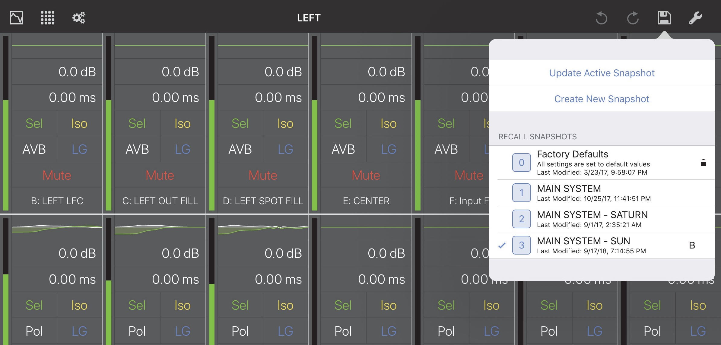
Settings View with Snapshots tab selected
Snapshots
A Snapshot contains all settings that configure a particular device. Each device has a:
Factory Default Snapshot: Includes typical settings to start with. It can be duplicated but not edited.
Boot Snapshot: Activated upon starting the device, and remains the Active Snapshot until another is loaded. If there is no Boot Snapshot, the device boots with its previous settings.
Active Snapshot: The Active Snapshot contains one instance of all GALAXY settings that are currently active in the GALAXY hardware.
Snapshot tab in Settings
Factory defaults
Tap Factory Defaults to recall the Factory Default settings.
Note
Enable AES3 output asynchronous sample rate converter
Create new snapshot
Tap Create New Snapshot to create a new Snapshot using this device’s current settings. This is now the Active Snapshot.
Clear active snapshot
Tap Clear Active Snapshot to clear the Active Snapshot. The device continues with its current settings and will use the Boot Snapshot (if one is assigned) next time it restarts.
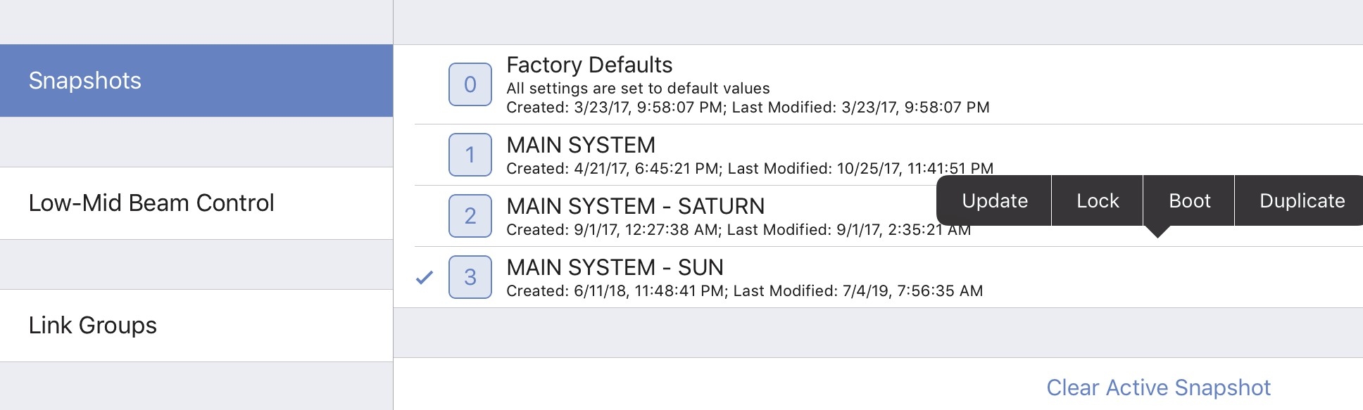
Snapshot assignment and editing options
In the figure above, MAIN SYSTEM - SUN is the Active Snapshot. Tap and hold any Snapshot. The following options are available (some states are context-sensitive and may appear inactive):
Update: Updates the Snapshot with the device’s current settings. The Factory Defaults Snapshot cannot be updated.
Lock or Unlock: Toggles the locked state of the Snapshot. When locked it, cannot be updated.
The Factory Defaults Snapshot cannot be unlocked.
Boot: Makes that Snapshot the Boot Snapshot.
Duplicate: Makes a copy of that Snapshot.
Note
There need not be an Active Snapshot. The device continues with its current settings
Clear boot snapshot
Tap Clear Boot Snapshot to remove it as the Boot Snapshot. A device without a Boot Snapshot restarts using its last settings before shutting down.
Low-mid beam control
Low Mid Beam Control (LMBC) is a tool that lets GALAXY users modify the natural vertical coverage of the low mid frequencies of a Meyer Sound line array to better match the high frequency coverage. Settings can be applied for up to four Arrays, each with up to 32 elements.
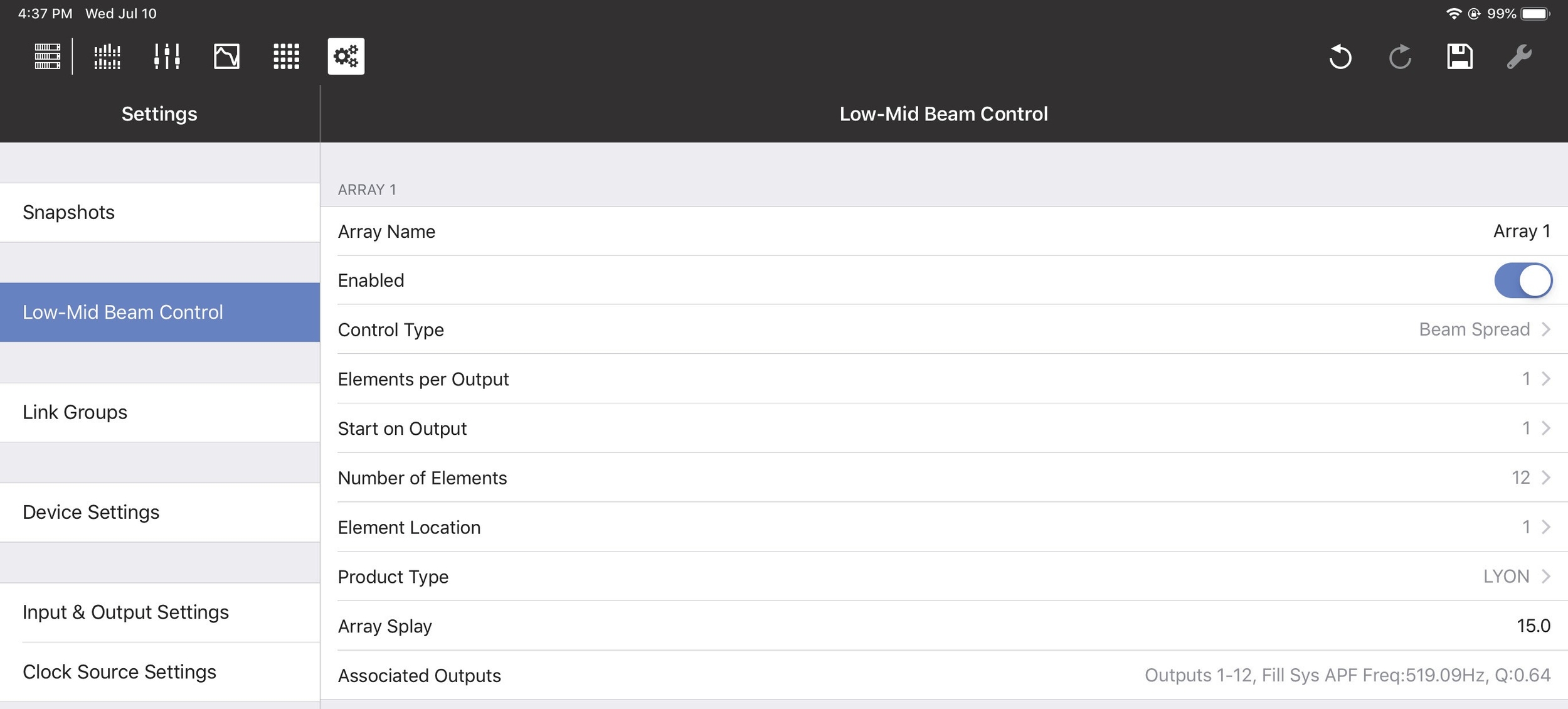
Low-Mid Beam Control tab
Low-mid beam control settings
Array Name: Lets you assign a name to the array (Flown Loudspeaker System). Enabled/Bypassed: This status button lets you enable or bypass LMBC for all affected channels. Control Type: The two options are Beam Spread and Steer Up.
Elements per Output: There can be one or two elements per output; this should match the physical connections in the array.
Start on Output: Selects the first output of the GALAXY processor where LMBC processing starts. Element 1 always starts at the top of the array.
Number of Elements: Sets the number of total elements in the array.
Element Location: Use this control when spanning multiple GALAXY processors if you have more than 16 elements that require more than 16 processor outputs.
For example, in an array with 22 elements, one element per output, and two processors:
Set the Number of Elements to 22 on both processors.
On the first processor, set Start On Output to 1, and set Element Location to 1.
On the second processor, set Start On Output to 1, and set Element Location to 17.
Product Type: Select the product type for this array from the list shown below:
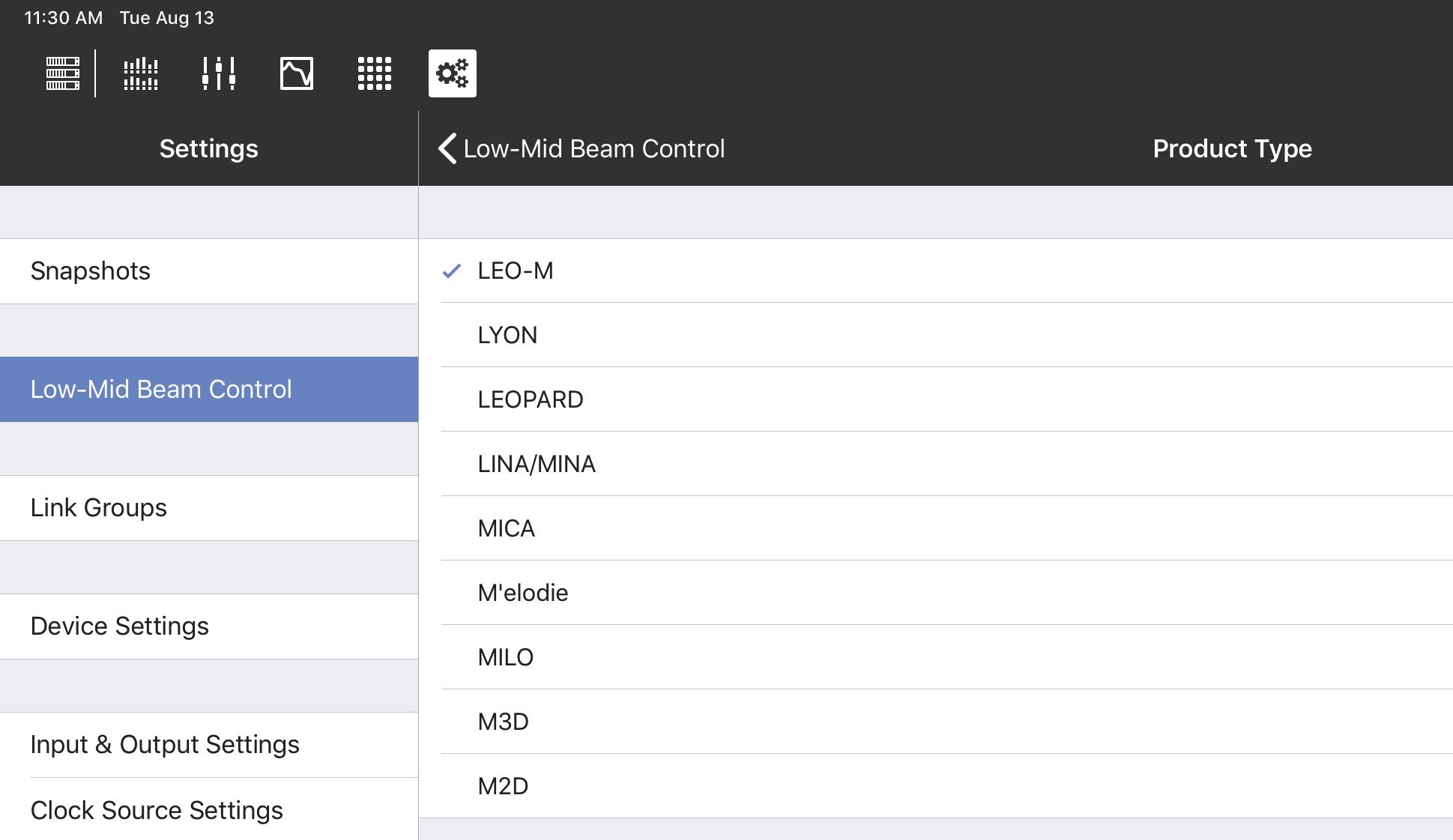
Product Types for LMBC
Array Splay: This is the sum total of the splay angles of the array.
Subtract the Rotation About Reference Point value from the Array Splay value shown at the bottom element of the Flown Loudspeaker System.
Enter the result in the Compass or Compass Go Array Splay column.
Set the splay angle between the top grid and the first element to 0º.
For example: If the MAPP Rotation About Reference Point = -2 and Array Splay = -56, then the LMBC
Array Splay = 54º.
Associated Outputs: This shows the device outputs in use with that LMBC array.
Note
If there is an error in the configuration, the Associated Outputs row turns red and its name changes to Error. A non-optimal configuration shows a warning in yellow.
Low-mid beam control operational tips
The following tips will help LMBC be more effective:
Signal drive lines must have correct polarity.
Apply LMBC before any other EQ.
Gain Tapering can make LMBC ineffective.
Do not treat array zones with different processing and/or gain below 1 kHz. For example, correct for low mid buildup with the same filters on the entire array, but correct for high frequency distance only above 1 kHz on individual zones.
Beam Spread is not optimal above 95º Array Splay.
Steer Up is not optimal above 45º Array Splay.
One array element per output is optimal.
Two array elements per output is maximum, and can only be used in an array with 12 or more elements.
Compass Software is designed to prevent invalid or non-optimal configurations.
LMBC is not designed to mix different product types in one array.
Set all speakers of the same type to the same Delay Integration pc setting.
When loudspeakers use separate outputs without LMBC, one all pass filter can be used to optimize align- ment with the LMBC outputs.
Link groups
Link Groups let you control multiple Inputs or Outputs simultaneously with one control. There are four Input Link Groups, and eight Output Link Groups.
Tap Link Group Name to enter a name for the Input or Output Link Group.
Input link groups (1–4)
Enable each Input Link Group you wish to control by sliding its button (Group 1, Group 2, etc.) to the right (it turns green). Then enable the Inputs (A–H) to include in that Input Link Group.
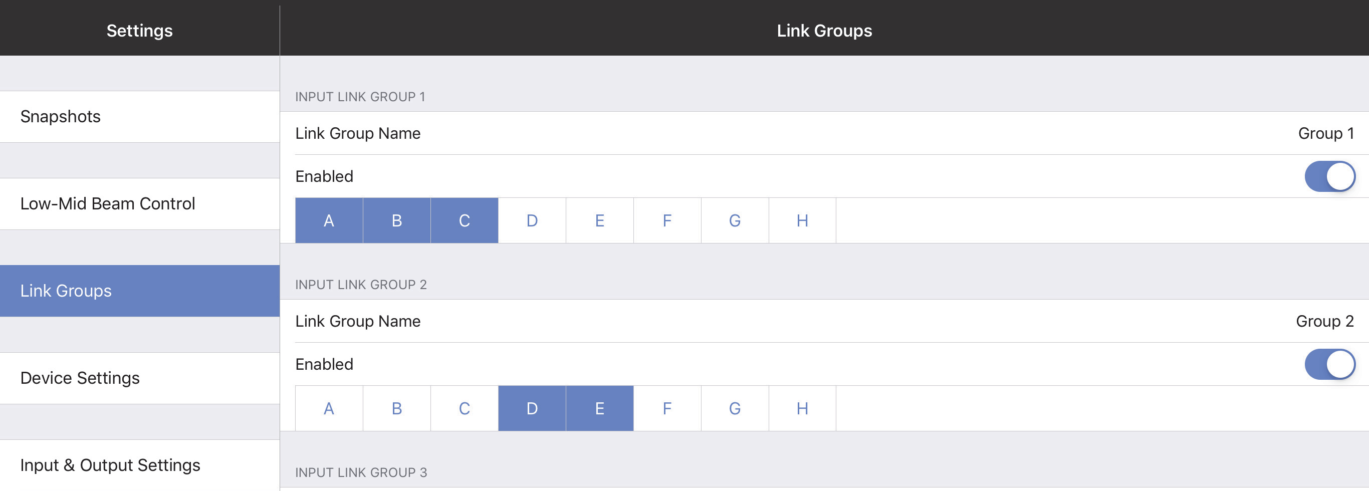
Input Link Groups from the Link Groups tab
Output Link groups (1–8)
Enable each Output Link Group you wish to control by sliding its button (Group 1, Group 2, etc.) to the right (it turns green). Then enable the Outputs (1–16) to include in that Output Link Group.
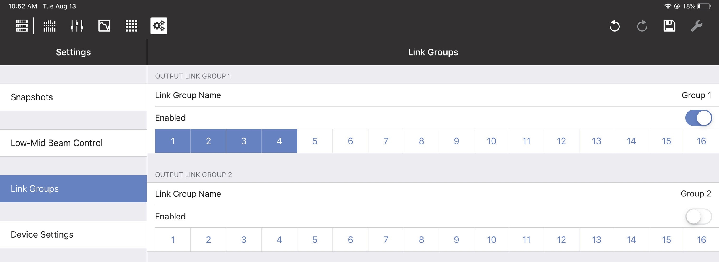
Output Link Groups from the Link Groups tab
Device settings
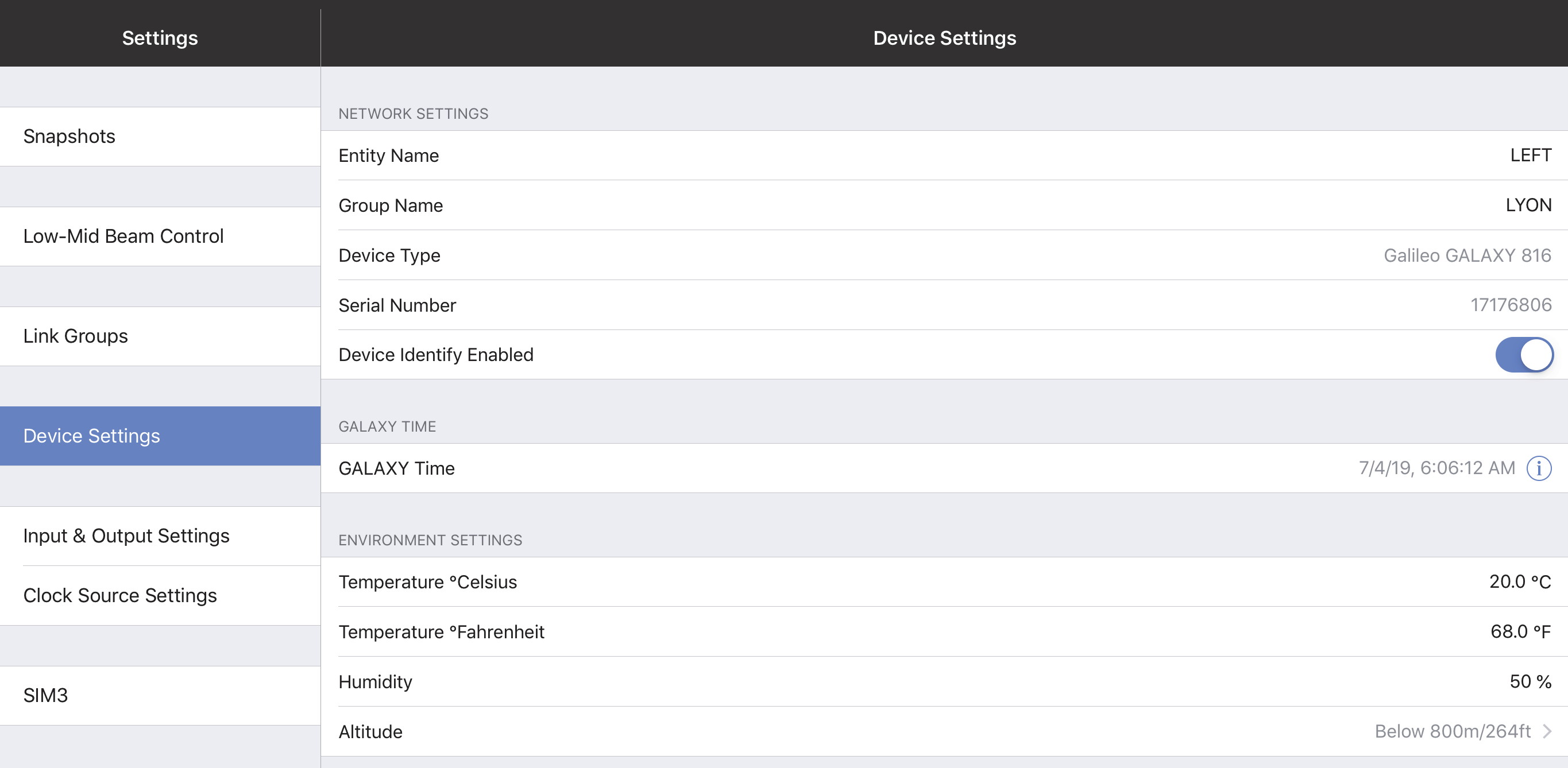
Device Settings tab
Network settings
These settings enable each device to uniquely identify itself on a network.
Device name
Initially, each Device receives an automatically generated name. To rename it, tap Device Name and use the onscreen keyboard.
Device group name
To assign a name to the Device Group, tap Device Group Name and use the onscreen keyboard.
Device type and serial number
These parameters are set at the Factory in each device and cannot be edited. Together, they uniquely identity each device (regardless of the user-assigned Device Name).
Device identity enabled
Slide the button to the right to cause this GALAXY device to identify itself by winking its rear panel Wink LED button and front panel display.
GALAXY time
The GALAXY Time can be edited using the fields shown by the figure below. Touch the date and time fields to set them manually.
Touch Set GALAXY Time to Local Time to set the time and date automatically.
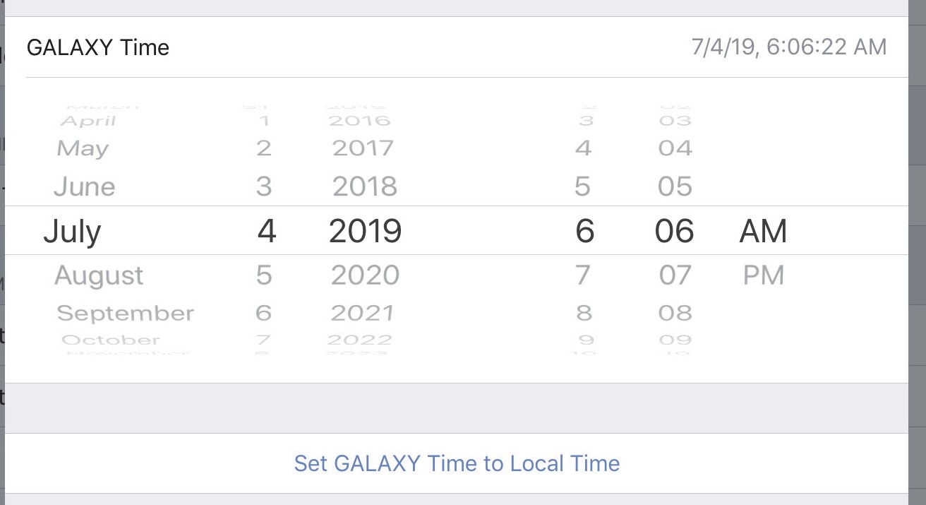
Setting the GALAXY Time
Environment settings
These values are used by the atmospheric correction algorithm (if enabled) and should be set to match the cur- rent operating environment.
Temperature Celsius
Temperature Fahrenheit
Humidity
Altitude
Input and output settings
This section lets you specify the types of Inputs and Outputs you wish to use.
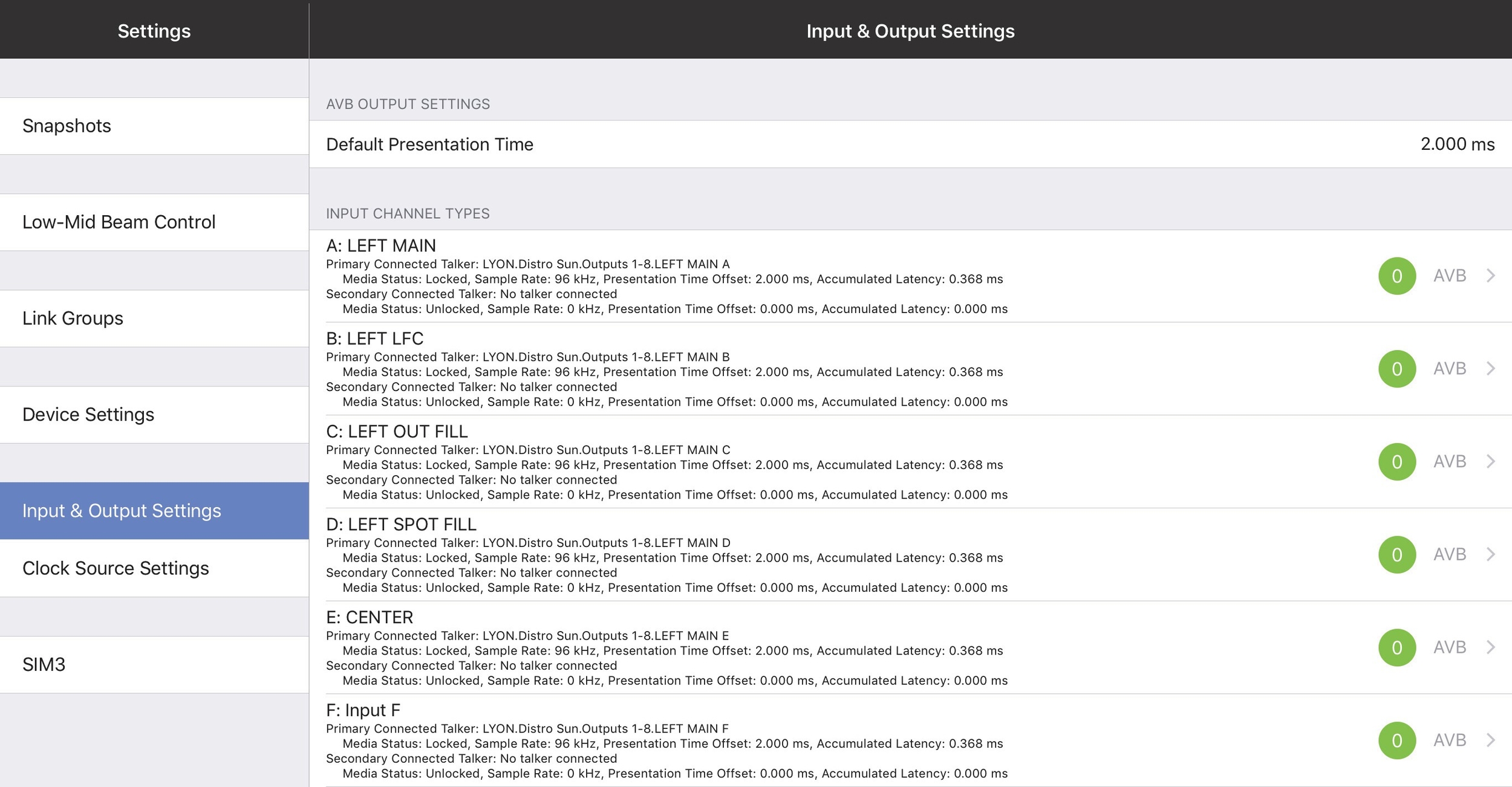
Input & Output Settings
Input & Output Settings
Default presentation time
Devices using the AVB I/O network periodically exchange timing information that allows both sides to precisely synchronize their time base reference clocks. This exchange of timing information allows an AVB listener to cal- culate the worst-case network transit time per stream, which is expressed as MSRP (Multiple Stream Reservation Protocol) Accumulated Latency. A network with one switch hop will typically have a smaller measured MSRP latency than one with several switch hops.
The Default Presentation Time lets the user obtain the lowest latency for AVB output streams in a given network topology without losing any audio samples.
Consider the following before choosing a Default Presentation Time setting:
The MSRP Accumulated Latency indicator displays the worst-case transit time through the network.
The Presentation Time Offset indicator is the maximum transit time handled by the AVB listener.
The Remaining Transit Time indicator is the time remaining between the packet reception and presentation time at the output.
Higher Default Presentation Time settings result in higher audio latency in the AVB streams.
Using a lower Default Presentation Time setting than the MSRP Accumulated Latency will lose audio samples, resulting in lower-quality audio. Therefore, always set the Default Presentation Time value higher than the MSRP. Include a margin of error to support possible changes to the network topology or bandwidth.
Note
To synchronize your local AES or analog input(s) to an incoming AVB stream with a given presentation time, add the appropriate amount of input delay to the desired non-AVB inputs. For example, if the AVB source’s default presentation time is 2 ms, set the input delay on each local device AES or analog input to 2 ms.
Input channel types
Input Types can be Analog, AES3, or AVB.
When the AES3 input and the GALAXY’s sample rate are the same, you can disable Enable Asynchronous Sample Rate Converter to reduce the latency introduced by the clock recovery. When disabled, you must use another method to synchronize the AES3 input with the GALAXY’s clock signal.

Input Channel Types
AVB connections
An AVB Stream functions much like an analog multi-cable. Each stream can vary in number of channels and format, similar to AES3 and standard analog multi-cables. The difference is that many audio streams can flow down a single Ethernet cable.
Unlike traditional multi-cables, AVB streams do not stay connected when the audio devices are turned off. An AVB software controller creates and maintains these connections running on a computer attached to the net- work or inside one of the audio devices being controlled. An AVB controller in the audio device will maintain persistent connections and remake connections after power cycle or other interruptions like unplugging an Ethernet link.
Each GALAXY has a built-in AVB controller. If GALAXY B’s inputs are subscribed to GALAXY A’s outputs for the first time using Compass software, GALAXY B’s AVB controller will attempt to remake that connection in case of any interruption.
GALAXY AVB streams are 24-bit/96 kHz 8-channel AAF packet format. AAF supports the transport of multi- channel 24-bit linear audio. Since GALAXY inputs can choose up to eight individual AVB channels from up to eight different streams, it is possible to send up to 8 eight-channel streams (64 channels) into the unit. How- ever, only eight of them are available for input processing. There are 24 additional AVB inputs available into the Gain, Delay, and Router matrices without input processing (see figure below).
Expanded Matrix Inputs
GALAXY outputs use two AAF formatted streams: Outputs 1–8 are available in the first 8-channel stream, out- puts 9–16 are available in the second 8-channel stream. If no units have subscribed to these streams, the GALAXY will stop transmitting altogether. The analog outputs are always active.
Network digital source signals can be connected to the AVB/Network port connectors (labeled 1 and 2) on the GALAXY rear panel. Standard AM824 eight-channel AVB streams are supported (24 bit, 48/96 kHz). The AVB Controller Mode can be set to External or Internal. AVB Stream Information can be viewed by selecting the status indicator next Input Channel Type if AVB is used for a given channel, as shown in the figure below.
AVB Connections cannot be edited by Compass Go. Use Compass Control Software to setup AVB connections. AVB Stream Information can be viewed by selecting the status indicator next to the Input Channel Type if AVB is used for a given channel.
Compass Control software is available at: https://meyersound.com/product/compass/

AVB Stream Information window
The figure below shows the Device Group, Device, available Stream, and Channel (to the right of the selected AVB) for a configuration using the Internal AVB Controller Mode in Compass Control Software. See Compass Control Software Help for more details.
The figure below shows a completed AVB connection.
Results of an Internal AVB Controller Mode configuration using Compass Software
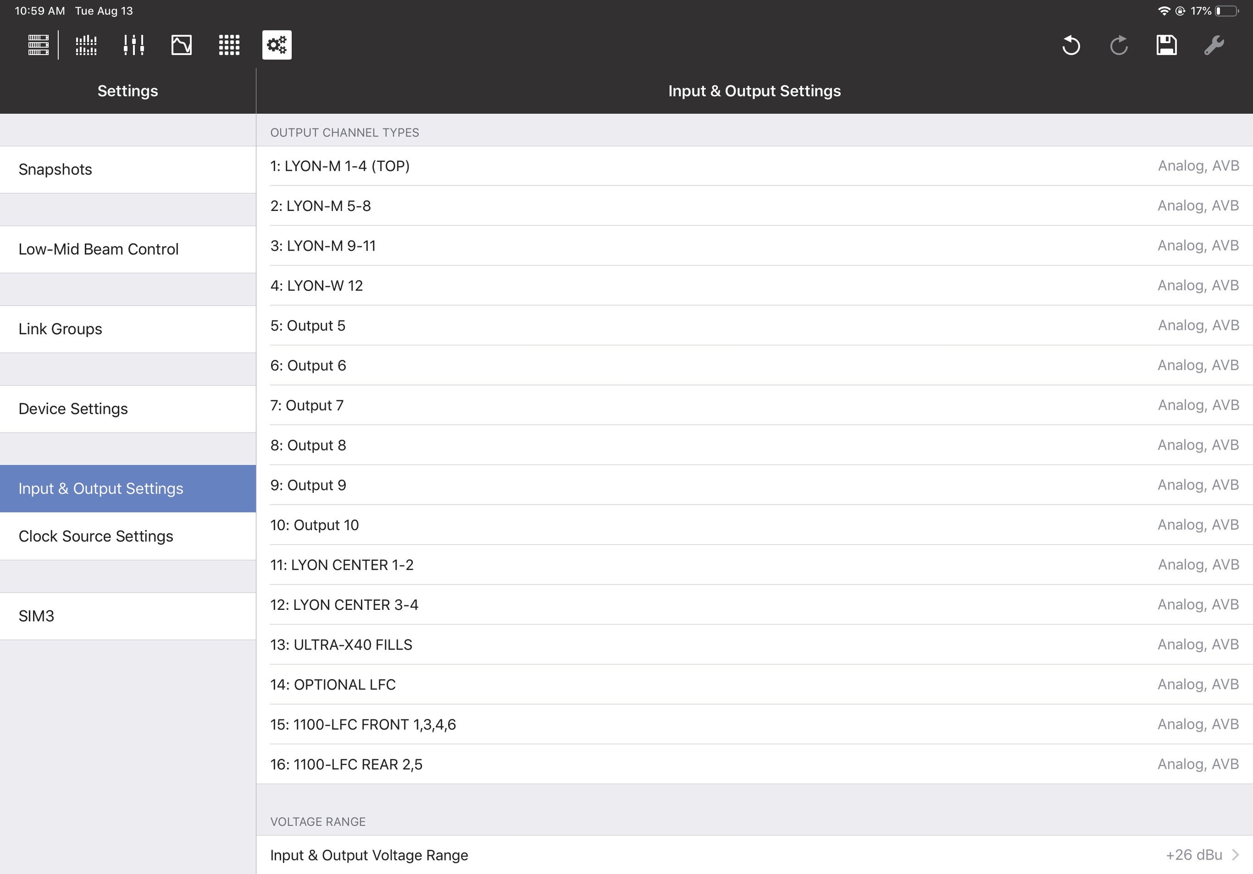
Input and output voltage range
The Input & Output Voltage Range can be set to +26 dBu or +16 dBu. To toggle the voltage range, tap the current value, select the other setting, and tap Done.
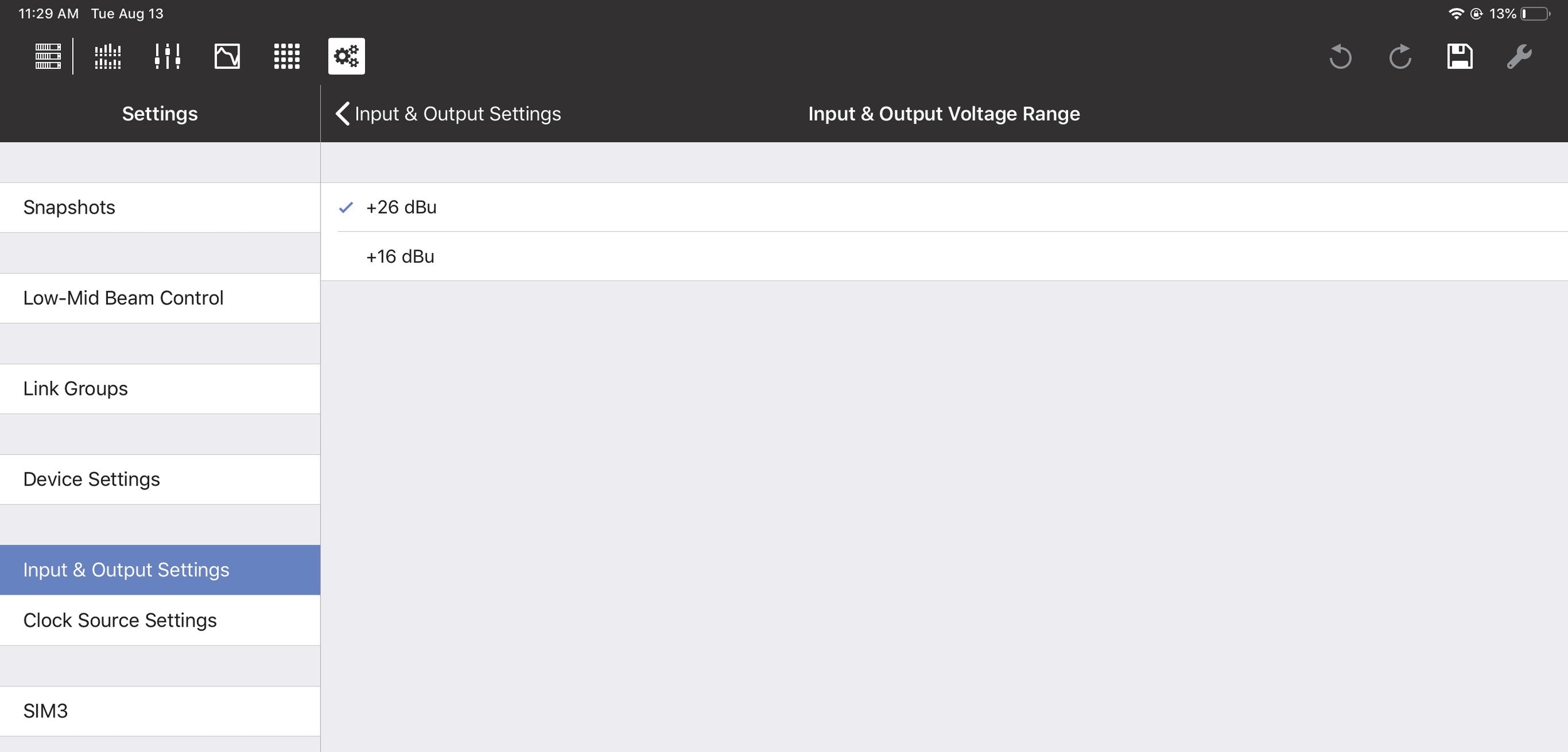
Input & Output Voltage Range
The Input & Output Voltage Range can be set for a different range of Input/Outputs on each GALAXY device:
GALAXY 816: Input/Outputs 1-16
The GALAXY 816-AES: Input/Outputs 9-16
The GALAXY 408: Input/Outputs 1-8
Clock source settings
These settings control how this device is synchronized within its system.
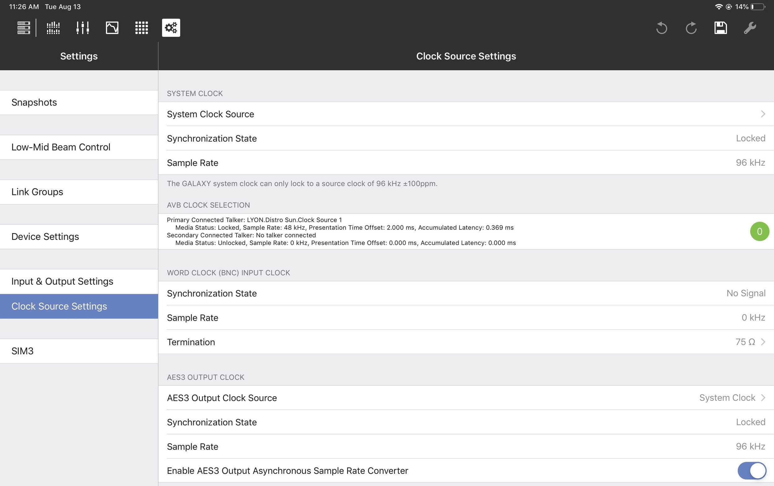
Clock Source Settings tab
System clock source
The System Clock Source can be set to Internal, AES3, AVB (if AVB connections have been established), or
Word Clock (BNC),
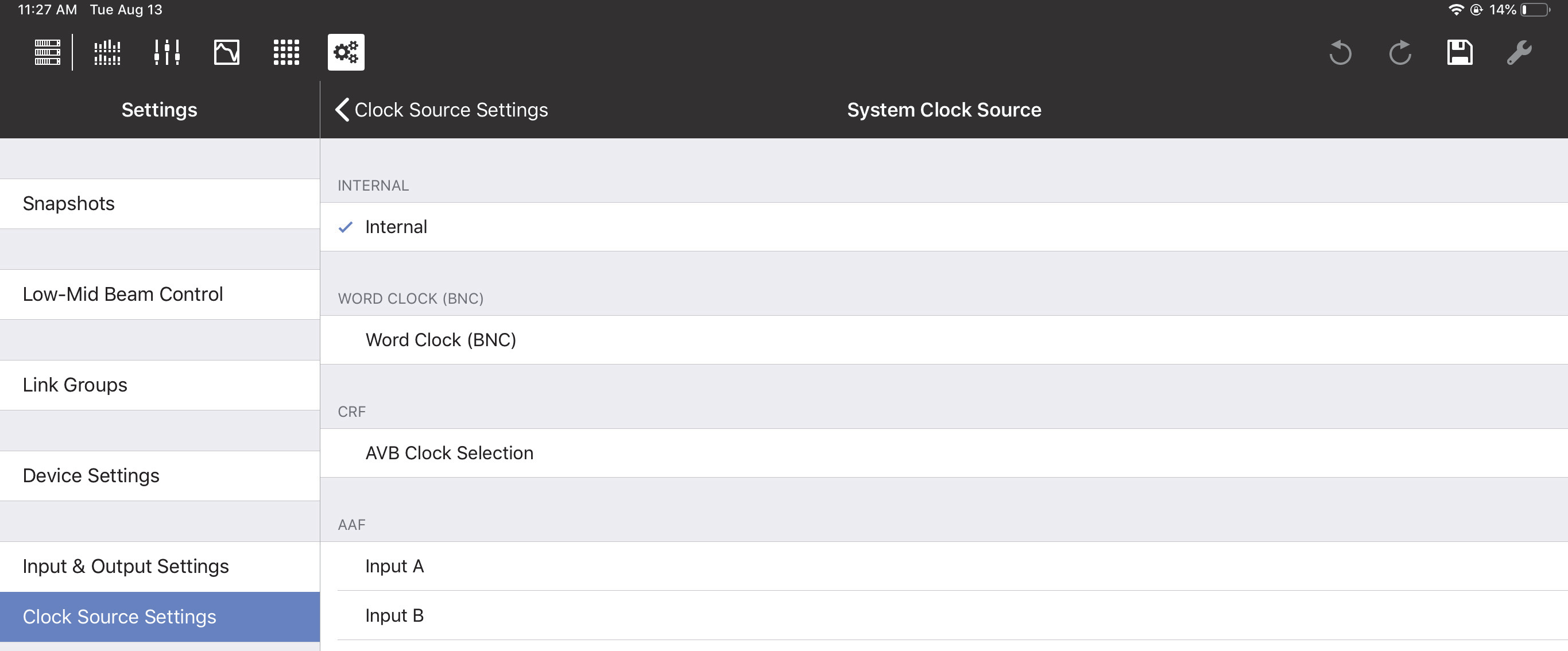
System Clock Source Settings
If using AES3:
Specify which Input to use as the System Clock Source.
The input and output system clocks may be different.
Note
If each device uses its own internal clock source, they will not stay synchronized.
Synchronization state
This field shows the status of the System Clock assignment: locked, unlocked, or no signal.
Sample rate
Sample Rate is set elsewhere and cannot be changed here.
AES3 output clock
This setting controls the synchronization of AES3 outputs.
AES3 output clock source
The AES3 Output Clock Source can be set to System Clock, AES3, or Word Clock (BNC). If using AES3, specify which Input to use as the Clock Source.
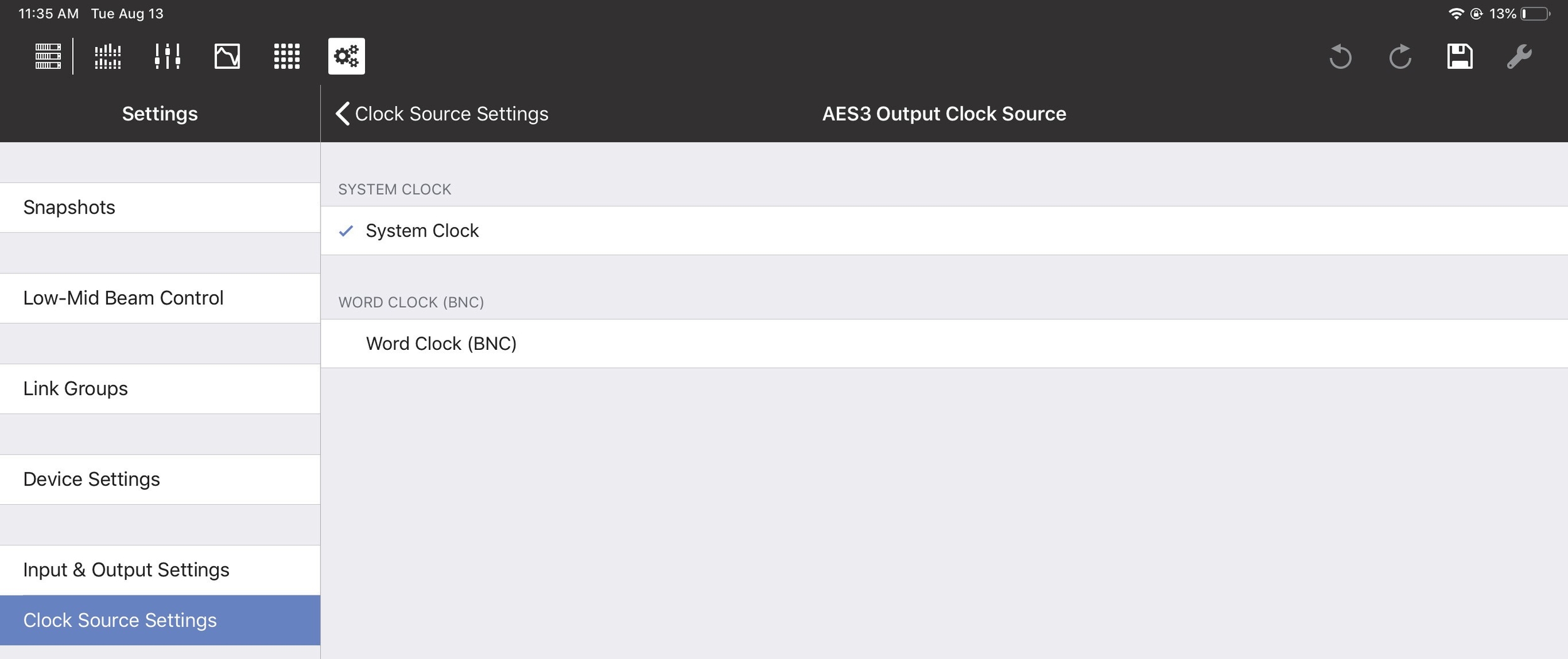
Setting the AES3 Output Clock Source
Synchronization state
This field shows the status of the System Clock Source assignment: locked, unlocked, or no signal.
Sample rate
Sample Rate is set elsewhere and cannot be changed here.
Enable AES3 output asynchronous sample rate converter
Slide the button to the right to enable the AES3 Output Asynchronous Sample Rate Converter.
SIM3
The Meyer Sound SIM3 Measurement and Correction System can be interfaced with GALAXY devices.
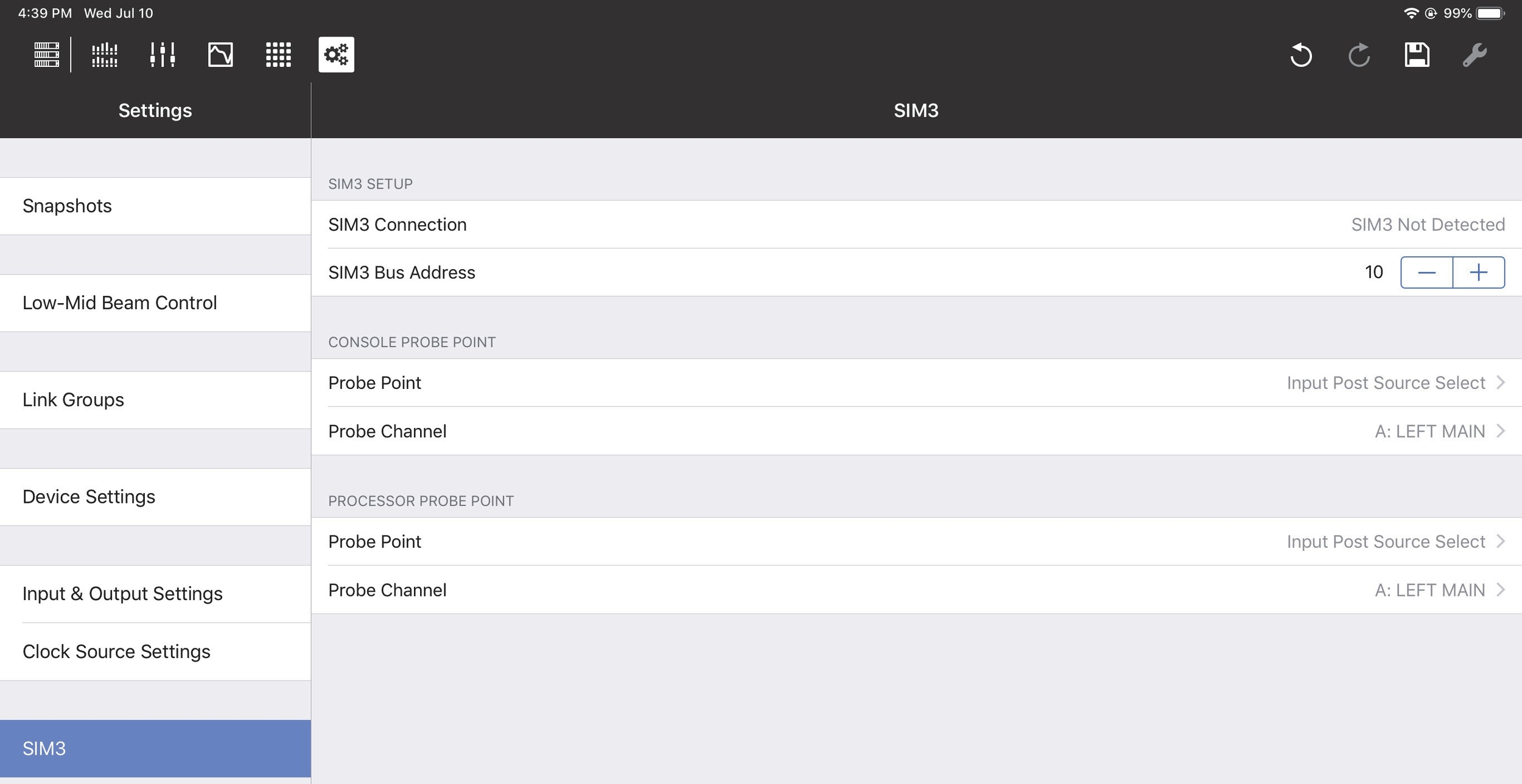
SIM3 options
SIM3 setup
Consult the SIM3 machine to determine its Bus address. In Compass Go, enter it in the SIM3 Bus Address field using the +/- buttons.
The SIM3 Connection field should now display SIM3 Detected.
Note
SIM3 can also be interfaced using the AVB network. Contact Meyer Sound Technical Sup-port for help with SIM3 (page 5).
Console and processor probe point and channel
The Console Probe Point, Console Probe Channel, Processor Probe Point, and Processor Probe Channel can be set to the following options:
Input Post Source Select
Input Post Processing
Output Post Matrix
Output Post EQ
Output Post Processing
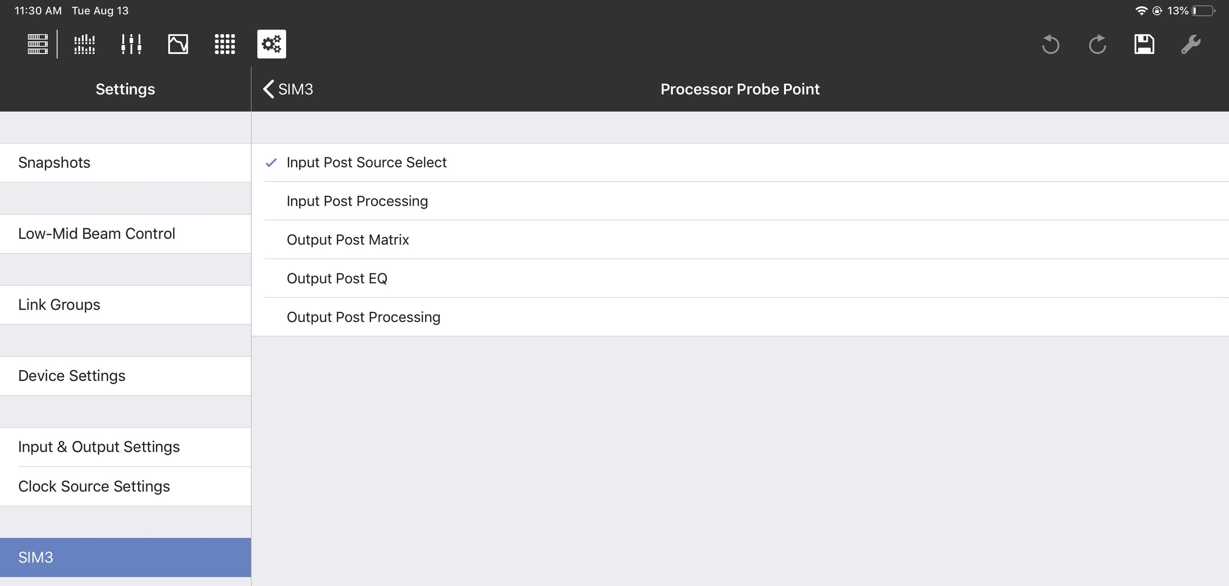
SIM3 Processor Probe options
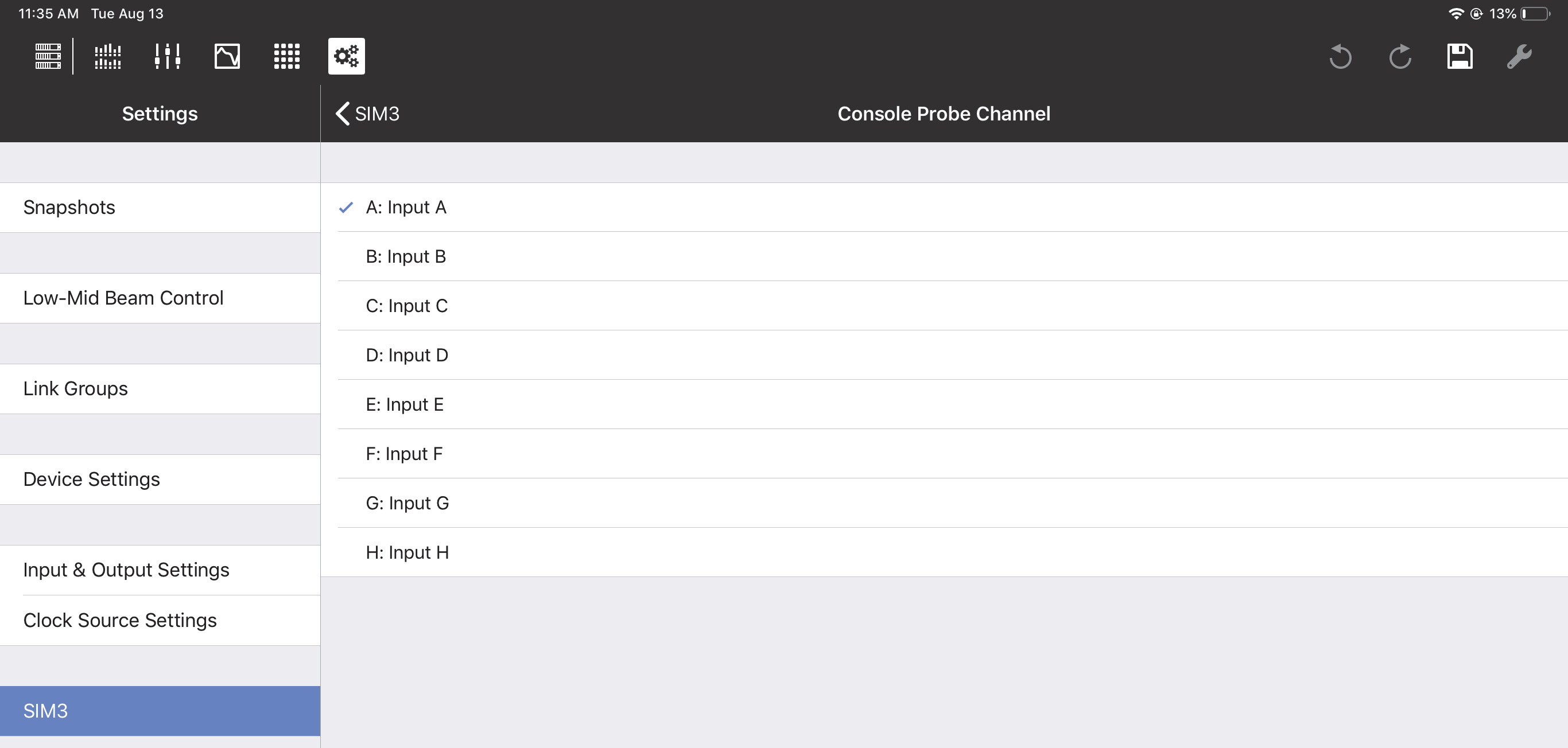
SIM3 Console Probe Channel options
Global controls
The Global Controls are at the top-right of each view.
Tools
The wrench icon accesses the Tools options, which differ for each view. See the end of the Overview, I/O, EQ, and Matrix View sections for details. Note that the Tools icon is dim and not available from the Settings View.
Save settings
The disk icon opens a dialog to update, create, and recall Snapshots.
Tap the disk icon to open the following dialog:
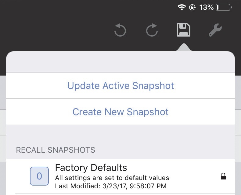
Disk icon with Snapshot options
Do one of the following:
Tap Update Active Snapshot to update the current Snapshot.
- OR -
Tap Create New Snapshot to create and name a new Snapshot.
- OR -
Tap a Snapshot in the RECALL SNAPSHOTS column to restore its saved settings.
Undo/redo editing
The most recent editing operation can be undone/redone with the standard circular controls.
Custom layouts
Custom Layouts let you use a single control to adjust settings on multiple Galileo, Galileo GALAXY, and Galileo Callisto devices. Custom Layouts can be spread across multiple views and can include background images. Views can be reordered and deleted.
Users with an iPad Pro can take advantage of the larger screen size by setting the Canvas Size to Large Canvas from the Tools menu (Small Canvas is the default setting).
Note
Setting a normal iPad to Large Canvas makes part of the screen not visible. Tap and drag to scroll the screen to see the extra screen space.
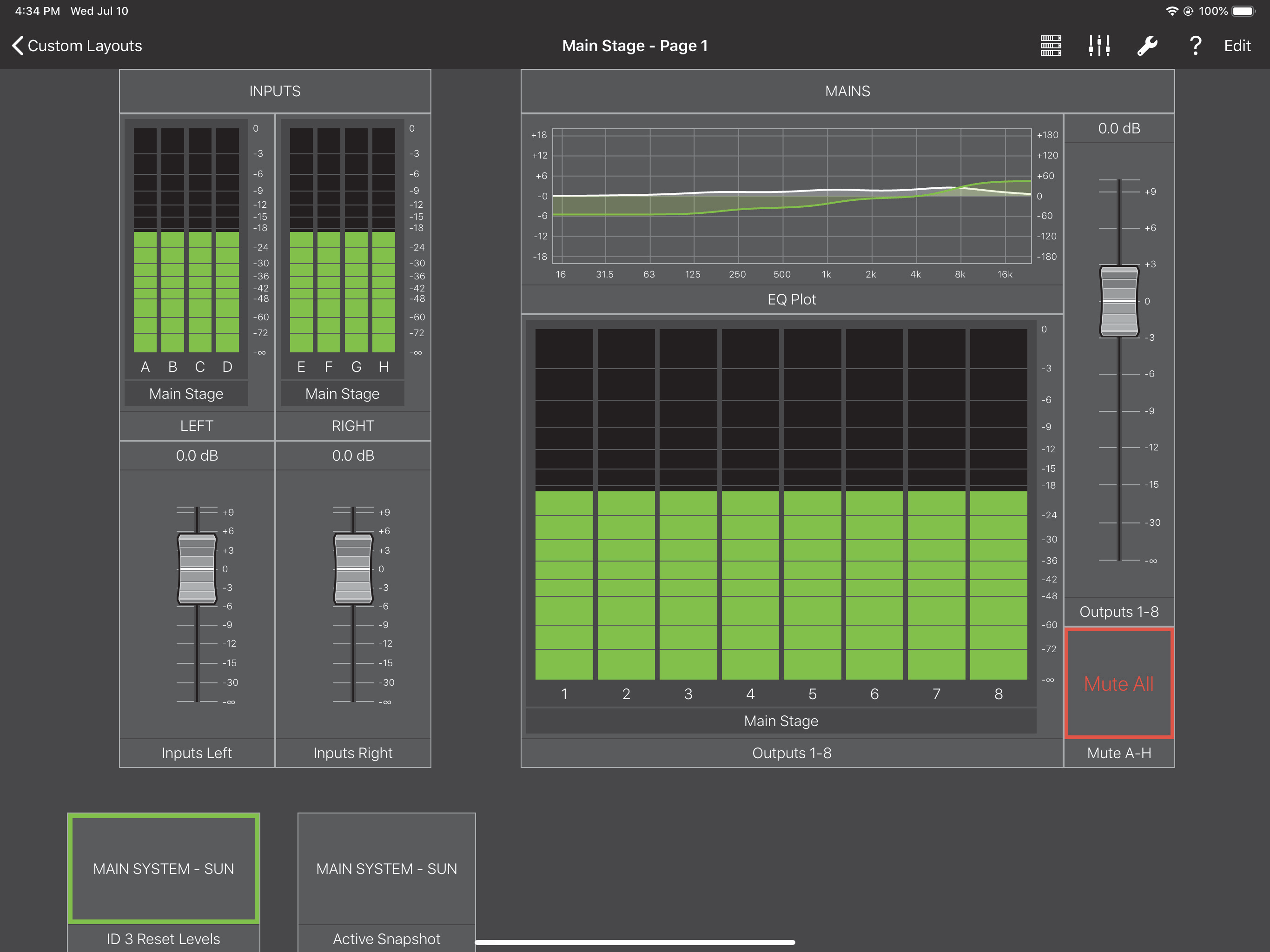
Custom Layouts View
Creating a custom layout
Tap Custom Layouts on the Devices View.
Tap Add Custom Layout.
A blank Custom Layout appears along with a keyboard to name it.
Name the Custom Layout.
Adding a device to a custom layout
Tap the Devices Icon from the top-right of your Custom Layout.
Tap Add Device.
The Add Device dialog appears.
Tap in the Device Name field and use the keyboard to assign a unique name so it is easy to identify.
Tap Device Type and choose from the corresponding Galileo, Galileo Callisto, or Galileo GALAXY types to match device in use.
Enable Device Auto Mapping by moving the switch to the right so it lights green.
Compass Go will automatically map this device next time the app is launched.
Tap the Devices Icon and select the devices to include in your Custom Layout.
Devices on the network are listed. A red dot to the left of the device shows it is not yet mapped. A yellow triangle shows it is mapped but disconnected.
If a device has a red dot, tap Map Devices.
The Map Devices dialog opens showing Devices already in this Custom Layout on the left and Discovered Devices on the right. Lines between the columns indicate valid mappings.
Tap a Device in either column that you wish to map.
Note
Only the same Device Types can be mapped to each other; incompatible device types are grayed out in each column.
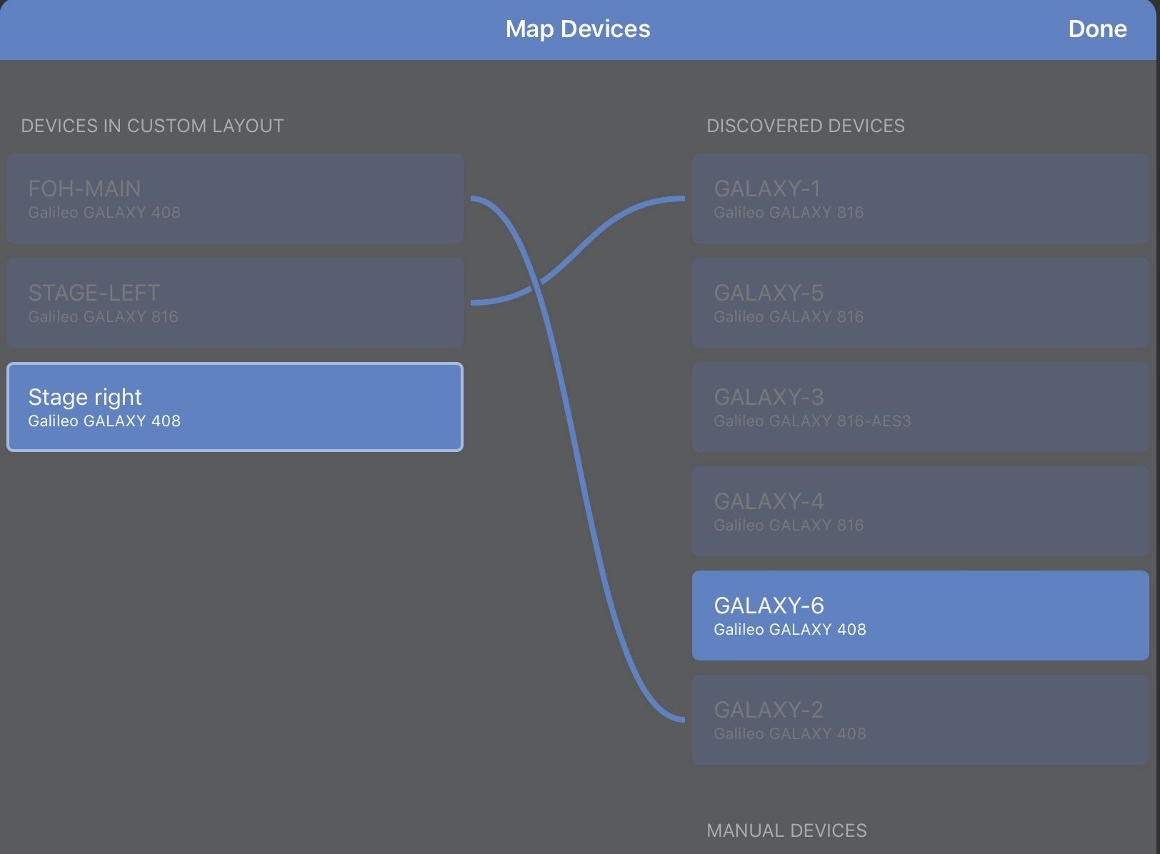
Devices valid for mapping
Tap the corresponding Device (in the other column) that you wish to connect to.
A line between the Devices shows the mapping was successful.
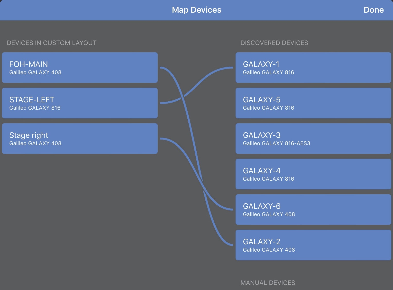
Devices successfully map
To unmap a mapped Device, tap the Device in either column, then tap the X that appears in the center of the line connecting them.
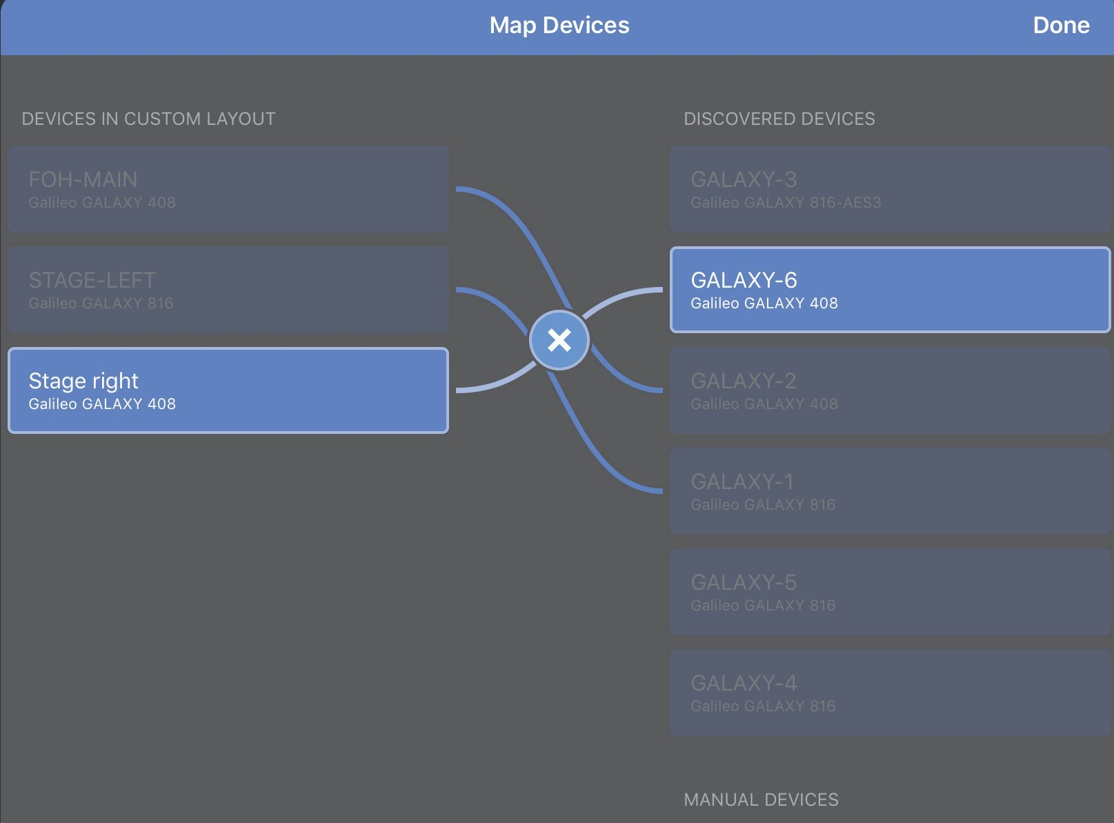
Devices being unmapped
Map each Device.
In the Devices menu, all Devices should have a green circle on their left.
Select a mapped Device to disconnect it but leave it mapped (yellow triangle).
Tip
Most controllers attempt to preserve the relative values of the multiple parameters they adjust if they differ. A blue band appears on the controller if this is the case.
Adding controls to a custom layout
Fader
Tap the I/O Icon in the menu bar, and select Fader. The Fader dialog opens.
Tap in the Control Label field and assign a name.
Tap in the Control Point Type field and select Gain.
Tap Channel Type and select Output.
Tap in the Channel Assignments section to select the Output channel(s) to control.
Tip
Most controllers attempt to preserve the relative values of the multiple parameters they adjust if they differ. A blue band appears on the controller if this is the case.
Rotary
Tap the I/O Icon in the menu bar, and select Rotary. The Rotary dialog opens.
Tap in the Control Label field and assign a name.
Tap in the Control Point Type field and select Delay.
Tap Channel Type and select Output.
Tap to select the Output channel(s) from the Channel Assignments section.
Spin Dial
Tap the I/O Icon in the menu bar, and select Spin Dial. The Spin Dial dialog opens.
Tap in the Control Label field and assign a name.
Tap in the Control Point Type field and select Delay.
Tap Channel Type and select Output.
Tap to select the Output channel(s) from the Channel Assignments section.
Wheel
Tap the I/O Icon in the menu bar, and select Wheel.
The Wheel dialog opens.
Tap in the Control Label field and assign a name.
Tap in the Control Point Type field and select Parametric EQ.
Tap Channel Type and select Output.
Tap Parametric EQ Attribute and select Gain.
Select a parametric Band.
Callistos have five bands of Output EQ, Galileo and Galaxy have 10.
If Input is the selected Channel Type, Callisto 616s are not available as they do not have parametric EQs on their inputs.
Tap to select the Output channel(s) from the Channel Assignments section.
Mute Button
Tap the I/O Icon in the menu bar, and select Mute Button. The Mute Button dialog opens.
Tap in the Control Label field and assign a name.
The Control Point Type field is automatically set to Mute.
Tap Channel Type and select Output.
Tap to select the Output channel(s) from the Channel Assignments section.
If Mute states differ among controlled channels, the label on the control changes from Mute All (or Unmute All) to Mute/Unmute. When tapped, a dialog appears with the following choices: Mute All, Unmute All, Toggle All, and Cancel.
Snapshot Recall
Tap the I/O Icon in the menu bar, and select Snapshot Recall.
Tap in the Control Label field and assign a name.
Tap the +/- controls to set the Snapshot ID to use for each device.
When the Snapshot control is tapped, the selected Snapshots are recalled into their respective devices.
Meter
Tap the I/O Icon in the menu bar, and select Meter.
The Meter dialog opens.
Tap in the Control Label field and assign a name.
The Control Point Type field is automatically set to Meter.
Tap Channel Type and select Input.
Tap to select an Input channel from the Channel Assignments section.
Response Curve
Tap the I/O Icon in menu bar, and select Response Curve. The Response Curve dialog opens.
Tap in the Control Label field and assign a name.
The Control Point Type field is automatically set to Response Curve.
Tap Channel Type and select Input.
Tap to select an Input channel from the Channel Assignments section.
Background image
Background images add context to a Custom Layout, making it easier to find and use controls. To add a Background Image to your Custom Layout:
Tap the I/O Icon in menu bar, and select Background Image (from the Miscellaneous section). The Photos dialog from your iPad opens.
Tap the folder containing your background image and select it.
The image appears as a background in your Custom Layout.
Background Images can be resized and moved when a Custom Layout is in Edit Mode.
From your Custom Layout View, tap Edit in the top-right of the menu bar.
To resize the image, use two fingers to pinch inward or expand outward to shrink or enlarge the image, respectively.
To move the image, tap it with two fingers and drag to the desired location.
Tap Done when finished.
Label
Labels add context to a Custom Layout, making it easier to remember how to use the controls.
Tap the I/O Icon in the menu bar, and select Label (from the Miscellaneous section). The Label dialog appears.
Tap to assign a name using the onscreen keyboard then tap Done.
The new Label appears in your Custom Layout.
From the Custom Layout containing the Label, tap Edit.
Edit handles now surround all controls and Labels on the Custom Layout.
Tap a Label.
The Label dialog appears.
Tap Delete Label.
Tip
Tapping the Label name also lets you rename the Label instead of deleting it.
Editing controls in a custom layout
Any control that appears in a Custom Layout can be cut, copied, deleted, and pasted within that Custom Layout, but you cannot edit between two Custom Layouts.
Tap Edit on the upper-right of the menu bar. Editing handles appear surrounding each control.
Tap and hold a control until you see Cut Control, Copy Control, Paste Control, Delete Control appear on top of it.
Touch to select Cut Control, Copy Control, or Delete Control.
With a control copied to the clipboard, tap and hold a blank area of the Custom Layout until you see Paste Control appear.
Touch Paste Control to paste the cut or copied control onto that area.
Each editing command behaves as follows:
Cut copies the control into the Custom Layout’s clipboard, then deletes that control from the view. Paste is now active.
Copy copies the control into the Custom Layout’s clipboard. Paste is now active,
Paste inserts the cut or copied control into the current Custom Layout View. The clipboard retains its conents for repeated Paste commands.
Delete removes the control from the view without copying it to the clipboard. Note that a previous Copy command may still reside in the clipboard.
Selecting a new custom layout
Navigate to the Compass Go Custom Layouts Library.
Tap a Custom Layout.
The new Custom Layout will automatically load.
Managing views in custom layouts
Views can be added, deleted, and reordered.

Managing Custom Layouts
Adding a view
In your Custom Layout (any view), tap the title at the top.
The Custom Layout views dialog opens showing the current views.
Tap Add view.
A blank view is added at the end of your current view list.
Deleting a view
In your Custom Layout (any view), tap the title at the top.
The Custom Layout views dialog opens showing the current views.
Swipe the desired view left.
A red Delete button appears at the right of the dialog.
Tap the Delete button to delete the view.
Reordering a view
In your Custom Layout (any view), tap the title at the top.
The Custom Layout views dialog opens showing the current views.
Tap and hold a view you wish to reorder.
A shadow appears around the outside of the view’s rectangle when it is selected.
Drag the view to its new location and release your finger.
Storing and sharing custom layouts
From the Custom Layouts Library View, tap Edit in the top-right of the menu bar.
All Custom Layouts appear with a selection circle to the left of each, and three horizontal bars to the right.
Tap anywhere (except on the three bars) to select the Custom Layouts to share or store.
Selected Custom Layouts display a check mark to their left.
Tap the Upload Icon in the top-right of the menu bar.
Choose Share or Save to iCloud Drive.
To reorder the Custom Layouts in your Library, tap and hold the three bars at the far-right of a Custom Layout until a rectangular shadow appears, then drag it to a new location.
Deleting custom layouts
In the Compass Go Custom Layouts Library, tap Edit in the top-right of the menu bar.
Tap to select the Custom Layouts you wish to delete.
A check mark appears beside selected Custom Layouts.
Tap the Trash icon.
Tap Done when finished.
- OR -
In the Compass Go Custom Layouts Library, swipe the Custom Layout you wish to delete to the left (do not tap Edit first).
A red Delete rectangle appears at the far right of the selected Custom Layout.
Tap Delete to confirm you wish to delete that Custom Layout.
Selecting Custom Layouts