Operating Instructions — Ultra XP
Point Source


Note
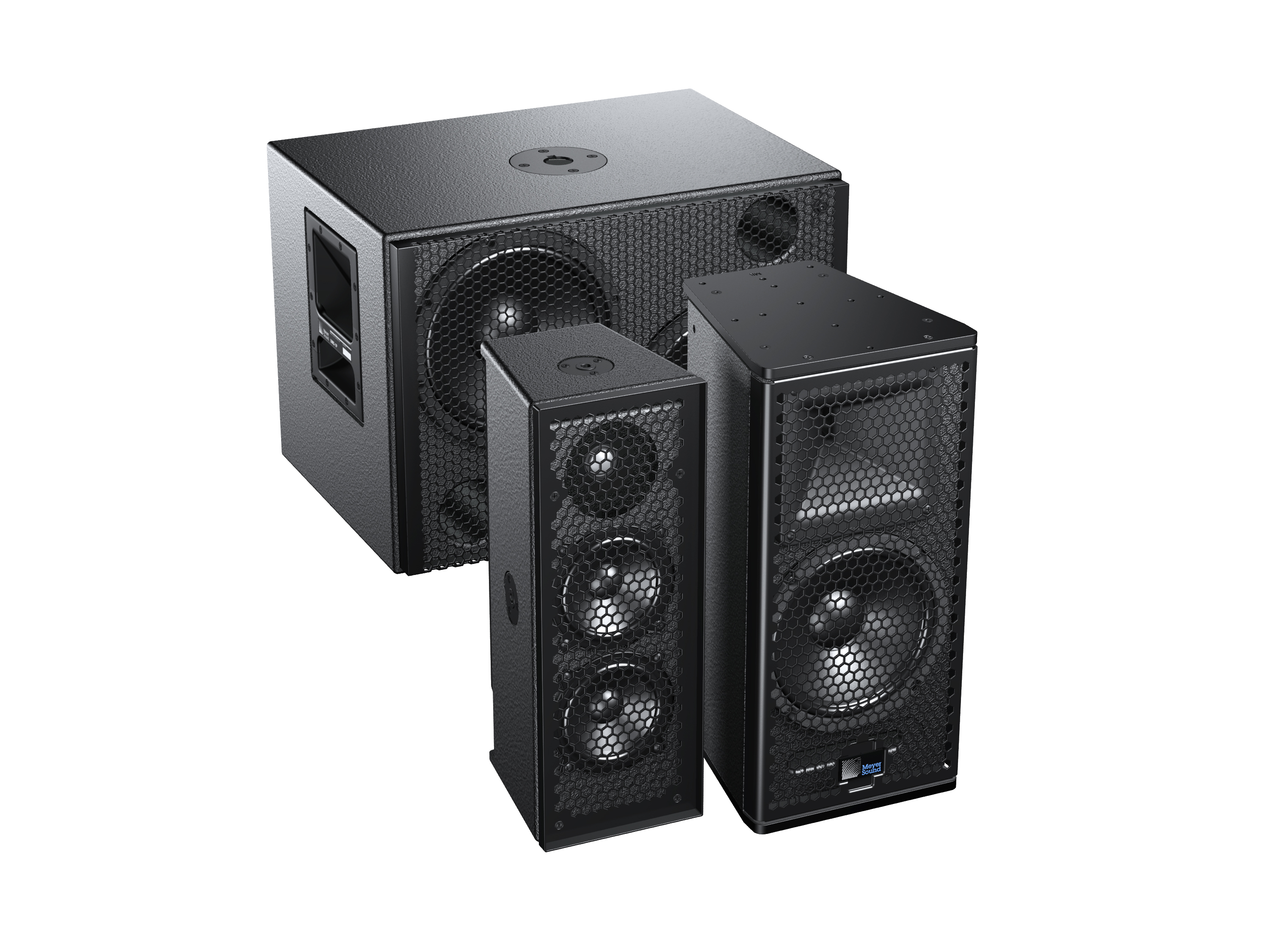
Collectively, these loudspeakers are referred to as Ultra XP.
Ultra XP loudspeakers (UPJ-1XP, UPJunior-XP, UPM-1XP, UPM-2XP, UMS-1XP) deliver the same sonic capabilities as their equivalent AC-based models, while also offering the advantages of IntelligentDC technology, making them an elegant solution for installations where AC cabling is not feasible. Powering Ultra XP loudspeakers from an external MPS-488HP IntelligentDC power supply affords the flexibility of lengthy cable runs without conduits.
With IntelligentDC technology, Ultra XP loudspeakers receive power and balanced audio from a single loudspeaker connector, available as a Phoenix™ 5-pin male, sealed Switch-Craft® EN3™ 5-pin male, or sealed ECO-M 7-pin male. The use of composite multiconductor cables (such as Belden® 1502 or equivalent) allows a single cable to carry both DC power and balanced audio to Ultra XP loudspeakers. Ultra XP amplifier and signal-processing circuits store DC power and tolerate voltage drops, thereby accommodating light-gauge cables and lengthy cable runs.
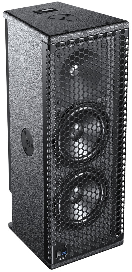
UPJ-1XP compact VariO loudspeaker
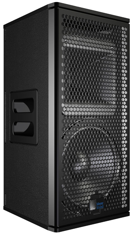
UPJ-1XP Loudspeaker
The UPJ-1XP compact VariO loudspeaker includes one 10-inch cone driver with a neodymium magnet and one 3-inch compression driver coupled to a rotatable, constant-directivity 80-degree by 50-degree horn. The loudspeaker is powered by a 2-channel, class D amplifier. The cabinet is constructed of premium birch plywood and includes side handles and heavy-duty, corrosion-resistant 6061-T6 aluminum end plates with threaded M8 attachment points for QuickFly rigging options, basic eyebolt rigging, and third-party pole assemblies.
UPJunior-XP UltraCompact VariO loudspeaker
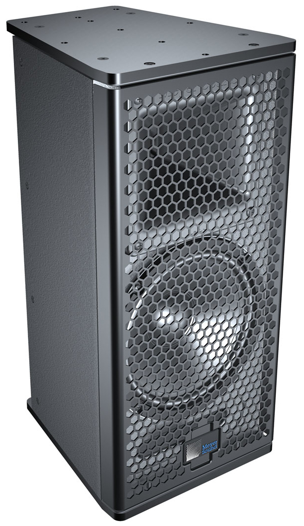
UPJunior-XP Loudspeaker
The UPJunior-XP UltraCompact VariO loudspeaker includes one 8-inch cone driver with a neodymium magnet and one 2-inch compression driver coupled to a rotatable, constant-directivity 80-degree by 50-degree horn. The loudspeaker is powered by a 2-channel, class-D amplifier. The cabinet is constructed of premium birch plywood and includes heavy-duty, corrosion-resistant 6061-T6 aluminum end plates with threaded M8 attachment points for QuickFly rigging options, basic eyebolt rigging, and third-party pole assemblies.
UPM-1XP UltraCompact wide-coverage loudspeaker
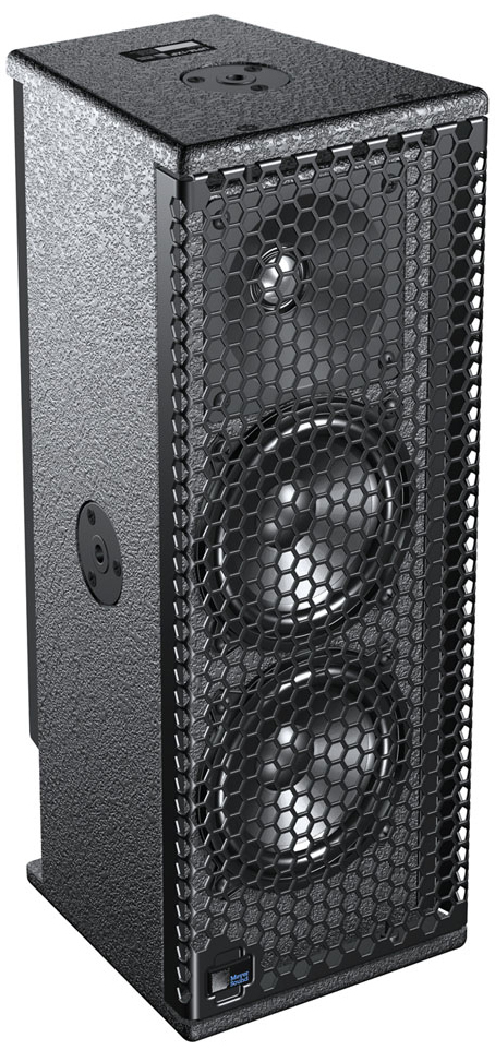
UPM-1XP Loudspeaker
The UPM-1XP UltraCompact wide-coverage loudspeaker includes two 5-inch cone drivers and one 1-inch metal dome tweeter on a constant-directivity, 100-degree symmetrical horn. The loudspeaker is powered by a 3-channel, class D amplifier. The cabinet is constructed of premium birch plywood and includes three 3/8”-16 or metric M10 nut plates.
UPM-2XP UltraCompact narrow-coverage loudspeaker
UPM-2XP Loudspeaker
The UPM-2XP UltraCompact narrow-coverage loudspeaker includes two 5-inch cone drivers and one 1-inch metal dome tweeter on a constant-directivity, 45-degree symmetrical horn. The loudspeaker is powered by a 3-channel, class D amplifier. The cabinet is constructed of premium birch plywood and includes three 3/8”-16 or metric M10 nut plates.
UMS-1XP UltraCompact subwoofer
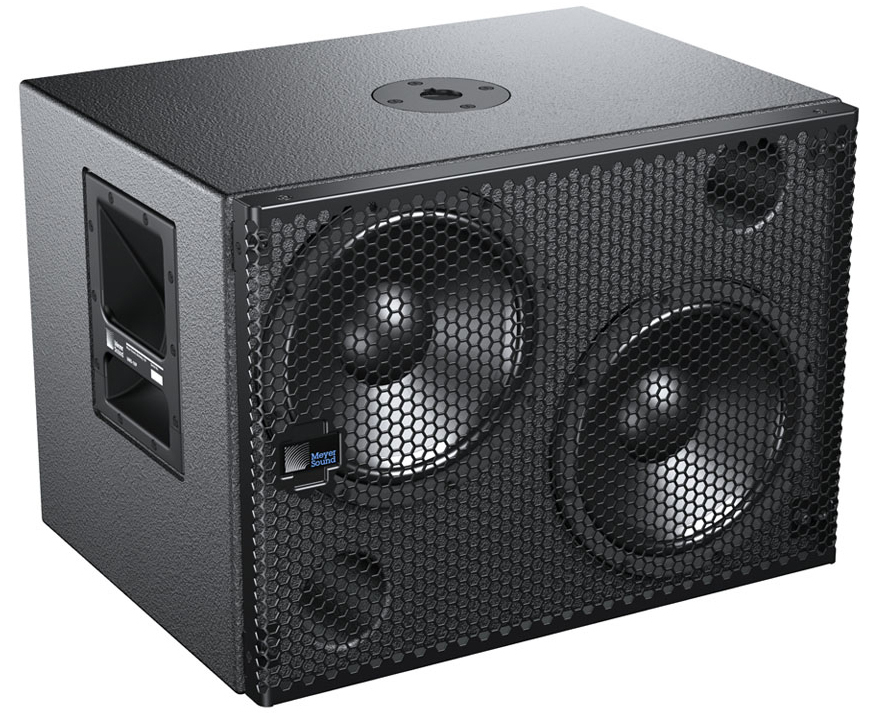
UMS-1XP Subwoofer
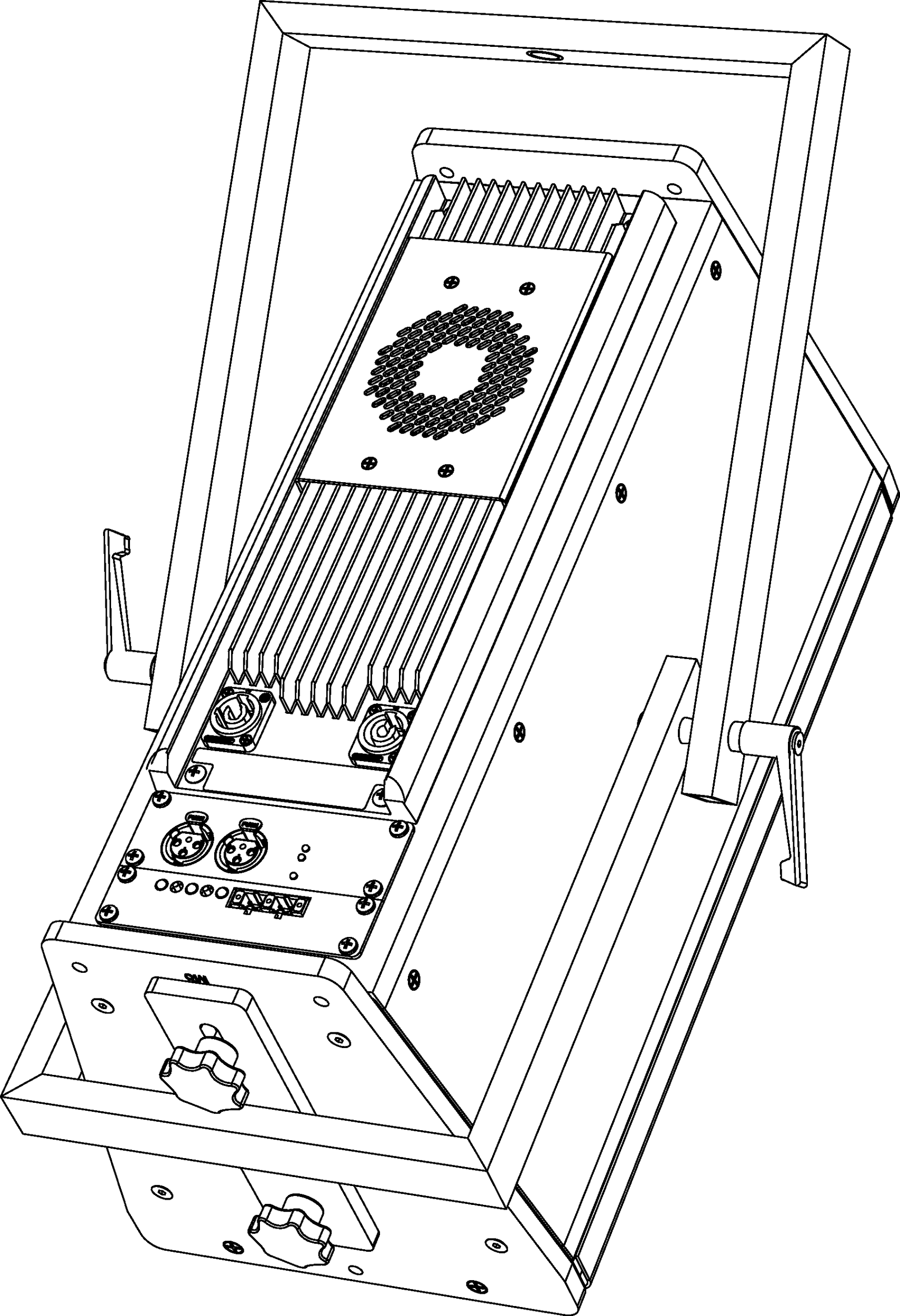
The UMS-1XP ultracompact subwoofer includes two 10-inch cone drivers. The subwoofer is powered by a 2-channel, class D amplifier. The cabinet is constructed of premium birch plywood and includes side handles and a pole-mount receptacle for pole-mounting UPJ-1XP, UPJunior-XP, UPM-1XP, and UPM-2XP loudspeakers. The cabinet is optionally available (UMS-SM subwoofer) with factory-installed threaded end plates for single-mount configurations with the UMS-SM U-bracket.
MPS-448HP IntelligentDC high-power eight-channel power supply
Ultra XP loudspeakers require an external MPS-488HP IntelligentDC power supply. The single-space 19-inch rack unit distributes DC power and balanced audio to up to eight Ultra XP loudspeakers, or other Meyer Sound IntelligentDC loudspeakers. Composite multiconductor cables, such as Belden 1502 or equivalent, can deliver both DC power and balanced audio to loudspeakers at cable lengths up to 150 feet with just 1 dB of loss in peak SPL using 18 AWG wire. Longer cable runs are possible with heavier gauges. Meyer Sound’s RMS remote monitoring system is optionally available for the MPS-488HP.
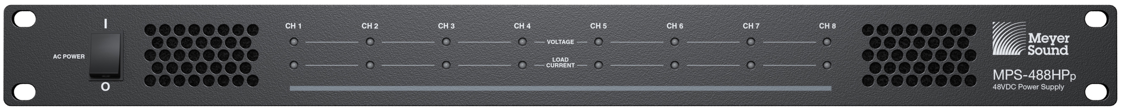
MPS-488HP IntelligentDC Power Supply
Caution
Disconnect the mains plug before disconnecting the power cord from the MPS-488HP.
Tip
For complete information on using the MPS-488HP IntelligentDC power supply, refer to the MPS-488HP Operating Instructions (PN 05.205.005.01).
Latency of Ultra XP loudspeakers
There is a very small latency of 1.58 ms for Ultra XP loudspeakers when compared to their equivalent AC-based models. This does not represent a problem when using Ultra XP loudspeakers with other Ultra XP loudspeakers. When mixing Ultra XP and AC loudspeakers in close proximity, this small latency can be easily addressed with a delay setting in a loudspeaker processor such as Meyer Sound’s Galileo GALAXY 408 or Galileo GALAXY 816.
ULTRA XP loudspeakers
Loudspeaker input connector
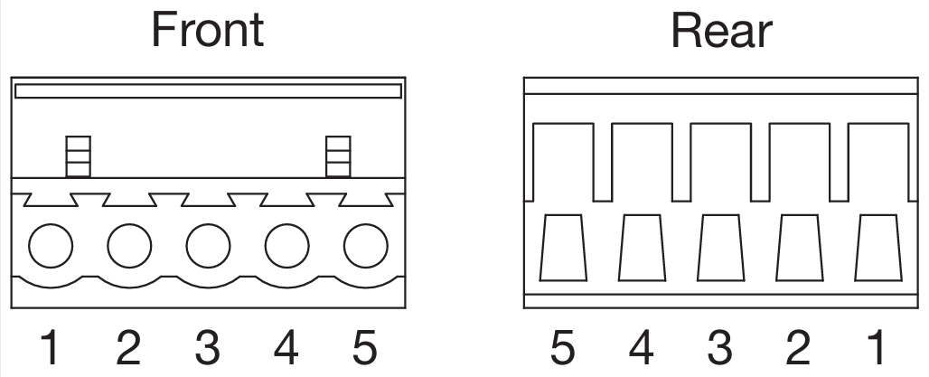
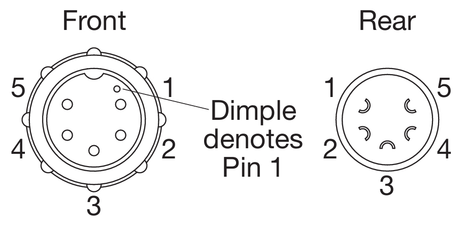
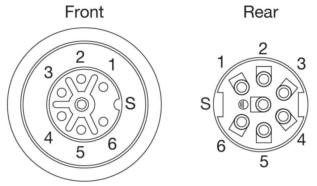
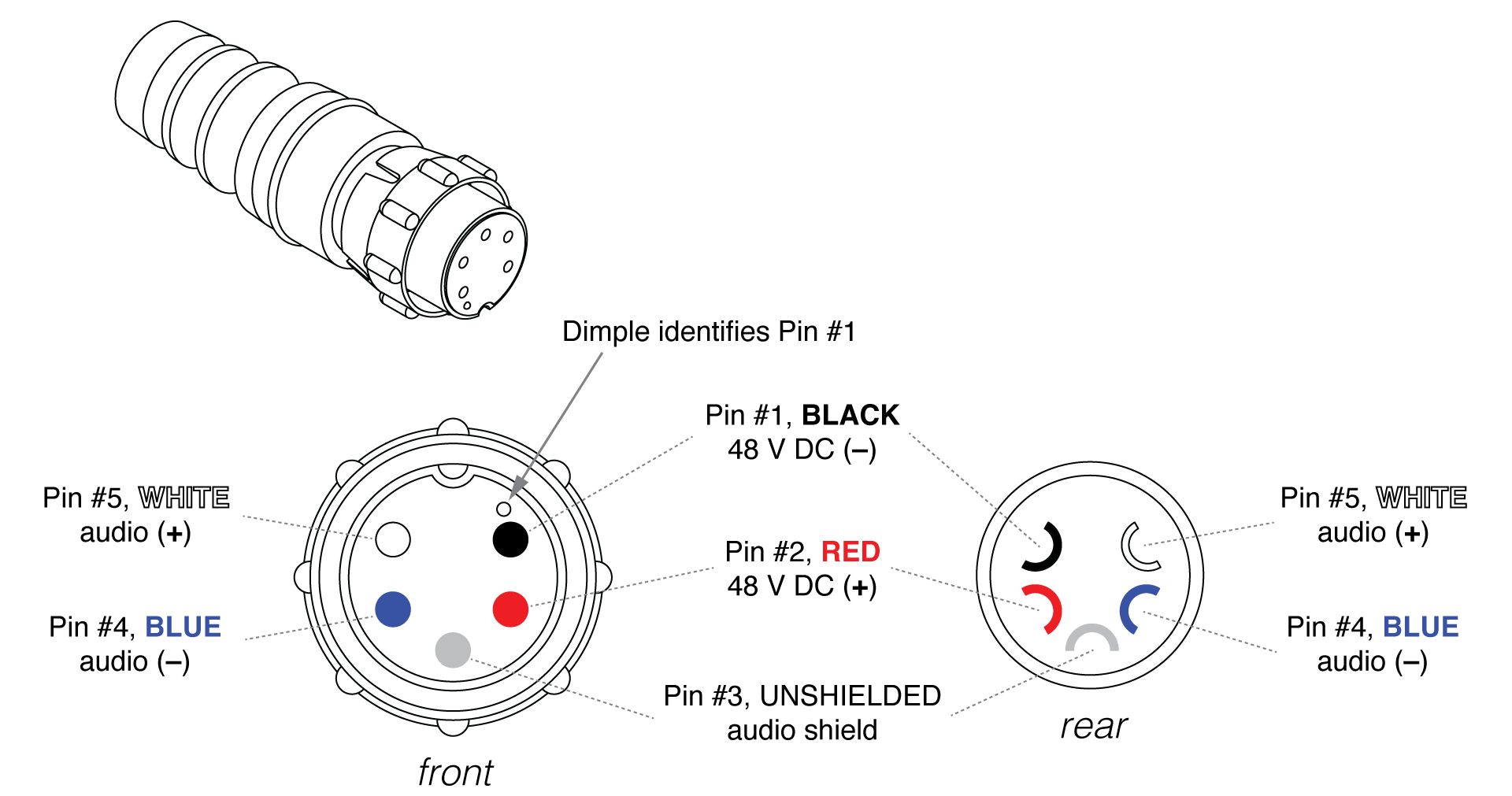
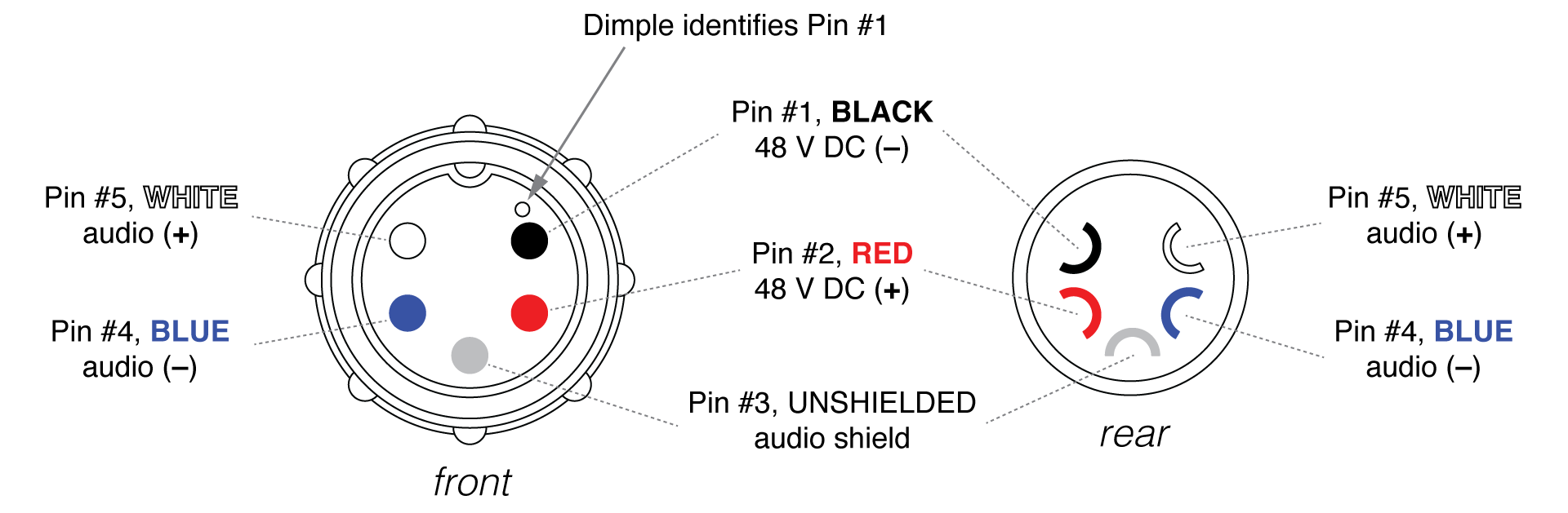
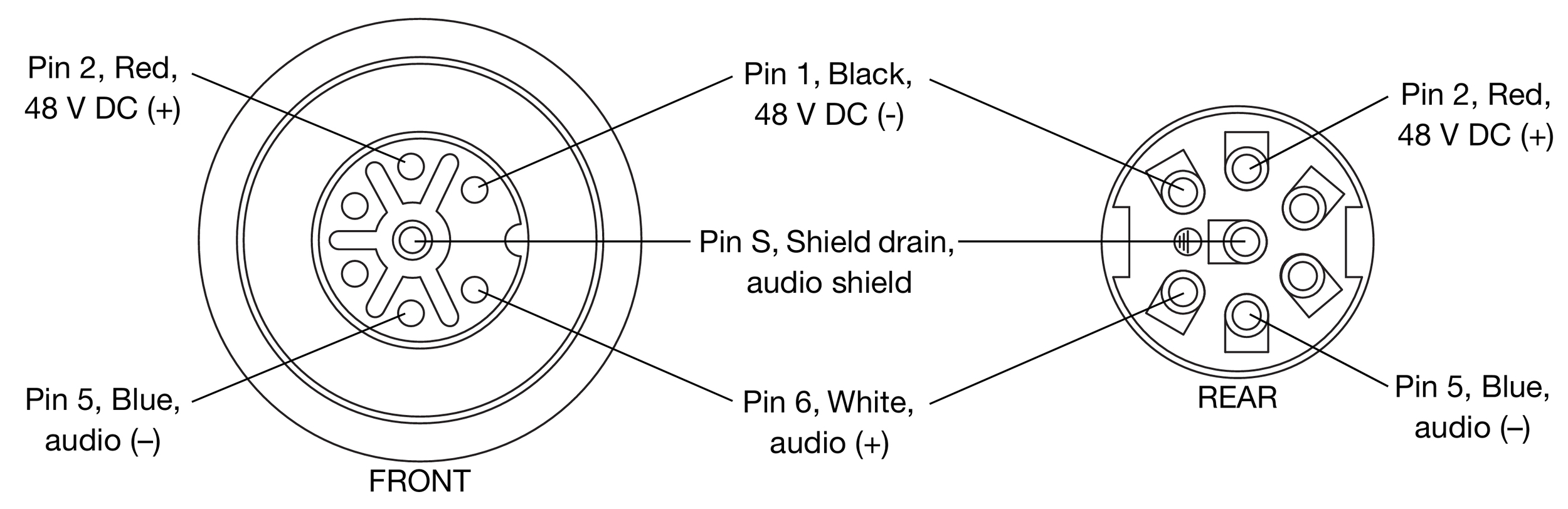
Ultra XP loudspeakers receive DC power and balanced audio from a single input connector, available as Phoenix™ 5-pin male, SwitchCraft® EN3™ 5-pin male, or ECO-M 7-pin male. The sealed EN3 and ECO-M connectors are ideal for outdoor, all-weather use. To function properly, Ultra XP loudspeakers require an external MPS-488HP IntelligentDC power supply.
All connectors include two pins for DC power (positive and negative) and three pins for balanced audio (positive, negative, and shield). Pin outputs are clearly labeled on loudspeaker user panels (pins 3 and 4 for ECO-M connectors are not used by Ultra XP loudspeakers). Ultra XP loudspeakers ship with an appropriate cable accessory for assembling loudspeaker cables (see the table below). For more information, see Belden 1502 Cable (or Equivalent) and Assembling Loudspeaker Cables
Phoenix 5-Pin Male | SwitchCraft EN3 5-Pin Male | ECO-M 7-Pin Male | ||
|---|---|---|---|---|
Loudspeaker connectors | 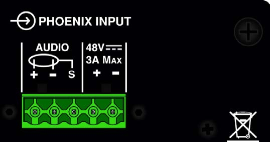 | 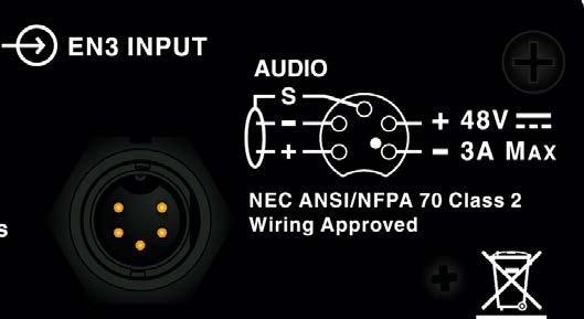 | 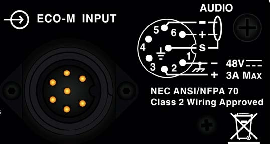 | |
Sealed (outdoor, all-weather use) | No | Yes | Yes | |
Included cable accessory | Phoenix 5-pin cable mount connector | EN3 5-pin-to-pigtail cable | ECO-M 7-pin cable mount connector | |
 |  |  | ||
Belden 1502 wiring | Pin Outs | |||
DC power (–) | Black | 1 | 1 | 1 |
DC power (+) | Red | 2 | 2 | 2 |
Audio shield | Sheild Drain | 3 | 3 | S (Shield) |
Audio (–) | Blue | 4 | 4 | 5 |
Audio (+) | White | 5 | 5 | 5 |
Caution
When wiring Ultra XP loudspeaker cables, it is extremely important that each pin be wired correctly. Make sure the 48 V DC from the Meyer Sound Intelligent DC power supply is wired directly (and only) to the 48 V DC pins on the loudspeaker connector, and that the polarity is observed (negative to negative, positive to positive) to avoid damage to the loudspeaker. In addition, make sure that audio pins are wired correctly; polarity reversals for audio signals affect system performance.
Current draw and cable requirements for ULTRA XP loudspeakers
DC current draw for Ultra XP loudspeakers is dynamic and fluctuates as operating levels change. Cabling between Ultra XP loudspeakers and their external power supply adds resistance and hence causes a voltage drop at the loudspeakers. Because lower DC voltages compromise amplifier performance (peak SPL), and in some cases frequency response, cable resistance should be kept to a minimum.
Cable Lengths and Cable Gauges
Cable lengths up to 150 feet between the Ultra XP loudspeakers and their external power supply are supported with only 1 dB of peak SPL loss using 18 AWG wire. Longer cable lengths are possible with heavier wire gauges as described in the tables below.
Cable Gauge | Resistance (Ω/ft) | Approximate Max. Length |
|---|---|---|
12 AWG | 0.0016 | 600 ft |
14 AWG | 0.00253 | 375 ft |
16 AWG | 0.00402 | 237 ft |
18 AWG | 0.00636 | 150 ft |
20 AWG | 0.01008 | 87 ft |
Cable Gauge | Resistance (Ω/m) | Approximate Max. Length |
|---|---|---|
2.50 mm2 | 0.0052 | 157 m |
1.50 mm2 | 0.01076 | 87 m |
1.00 mm2 | 0.02087 | 45 m |
0.75 mm2 | 0.03307 | 27 m |
Note
The total cable resistance between Ultra XP loudspeakers and their external power supply should not exceed 2 ohms.
For long cable runs, you can use a large cable gauge for DC power and a separate balanced audio cable for audio. For more information, see “Long Cable Runs with Separate Cable for DC Power and Audio” on page 11.
Calculating the Maximum Cable Length
The maximum cable length for an Ultra XP loudspeaker can be calculated with the following formula:
maximum length = 2 ohms / 2 * cable resistance
For example, the maximum length of an 18 AWG cable with a resistance of 0.00636 is 157.2 feet (2 / 2 * 0.00636).
Belden 1502 cable (or equivalent)
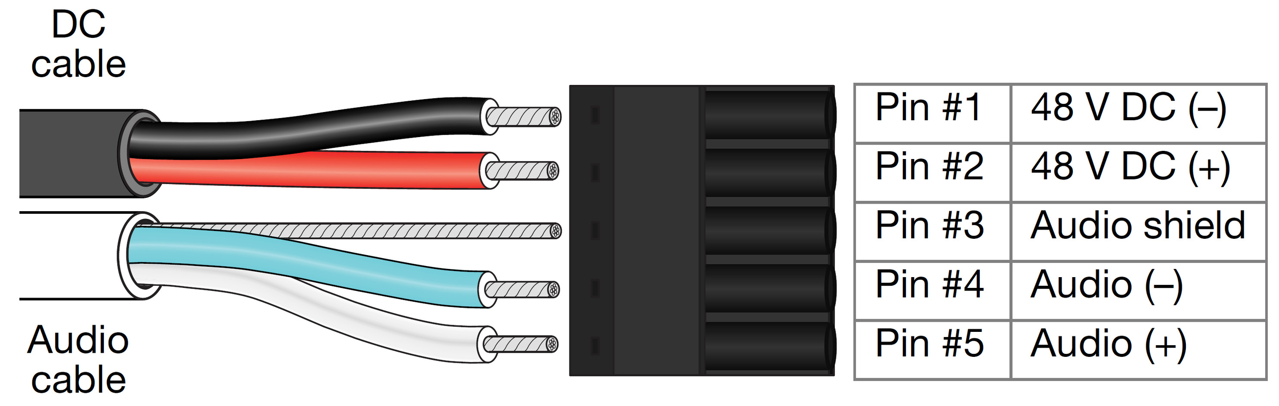
The most convenient method of wiring Ultra XP loudspeaker cables is with a multiconductor cable such as Belden 1502, which has dedicated conductors for DC power and balanced audio in a single jacket. When wiring loudspeaker cables with Belden 1502, use the conventions in the table below.
The red and black wires are 18 AWG, thicker than the other three wires, and should be used for DC power (cable lengths up to 150 feet are possible with just 1 dB of peak SPL loss). The blue, white, and shield drain wires should be used for audio.

Belden 1502 Composite Cable
Wire | Signal | Gauge |
|---|---|---|
Black | 48 V DC power, negative (–) | 18 AWG |
Red | 48 V DC power, positive (+) | 18 AWG |
Shield drain | Balanced audio, shield | 24 AWG |
Blue | Balanced audio, negative (–) | 22 AWG |
White | Balanced audio, positive (+) | 22 AWG |
Caution
When wiring Ultra XP loudspeaker cables, it is extremely important that each pin be wired correctly. Make sure the 48 V DC from the external power supply is wired directly (and only) to the 48 V DC pins on the loudspeaker connector, and that the polarity is observed (negative to negative, positive to positive) to avoid damage to the loudspeaker. In addition, make sure that audio pins are wired correctly; polarity reversals for audio signals affect system performance.
Note
For more information on cable assembly, refer to Assemble IntelligentDC loudspeaker cables.
For a complete list of available cables and cable accessories from Meyer Sound, refer to Ultra XP Accessories.
Long cable runs with separate cable for DC power and audio
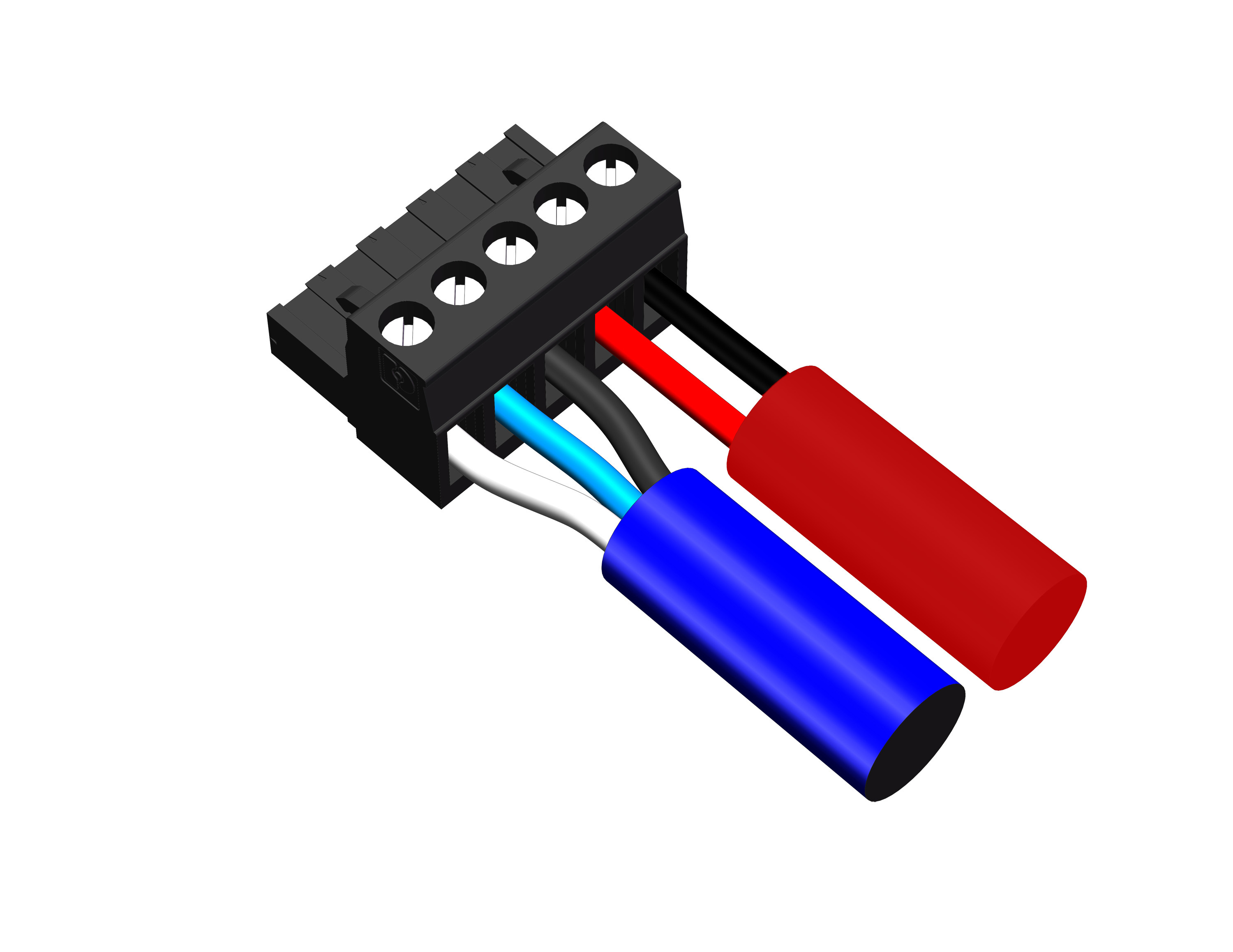
For installations where Belden 1502 is not feasible, or for installations that require cable runs longer than 150 feet, you can use separate cables for DC power and balanced audio: a large-gauge cable for DC and a high-quality, balanced audio cable for audio. The separate cables attach to the Phoenix connector at the loudspeaker as shown in the figure below. Cable runs longer than 150 feet for DC power require cable gauges larger than 18 AWG; for more information, see Cable Lengths and Cable Gauges.
Separate Cables for DC Power and Balanced Audio
EN3-to-pigtail cables
Ultra XP loudspeakers with EN3 connectors ship with an EN3 5-pin-to-pigtail cable. The EN3 end of the cable connects directly to the loudspeaker input connector. The pigtail end of the cable, which connects to the external power supply, can be terminated with either an EN3 5-pin male connector (included with the MPS-488HPe) or a Phoenix 5-pin female connector (included with the MPS-488HPp). The pigtail can also be spliced to a longer loudspeaker cable or to a junction box. The EN3-to-pigtail cable uses Belden 1502 cable (or equivalent), which can be wired for both DC power and balanced audio. The EN3-to-pigtail cable is available in plenum or regular (non-plenum) versions.
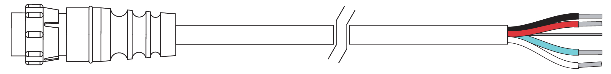
EN3-to-Pigtail Cable
Limit LEDs
When source levels for an Ultra XP loudspeaker exceed maximum input levels for its drivers, limiting is engaged and is indicated by the two Limit LEDs on the rear user panel.
The bottom LED indicates limiting for low-frequency channels. The top LED indicates limiting for high-frequency channels. When engaged, limiting not only protects the drivers, but also prevents signal peaks from causing excessive distortion in the amplifier’s channels, thereby preserving headroom and maintaining smooth frequency responses at high levels. When source levels return to normal, below the limiter’s threshold, limiting ceases.
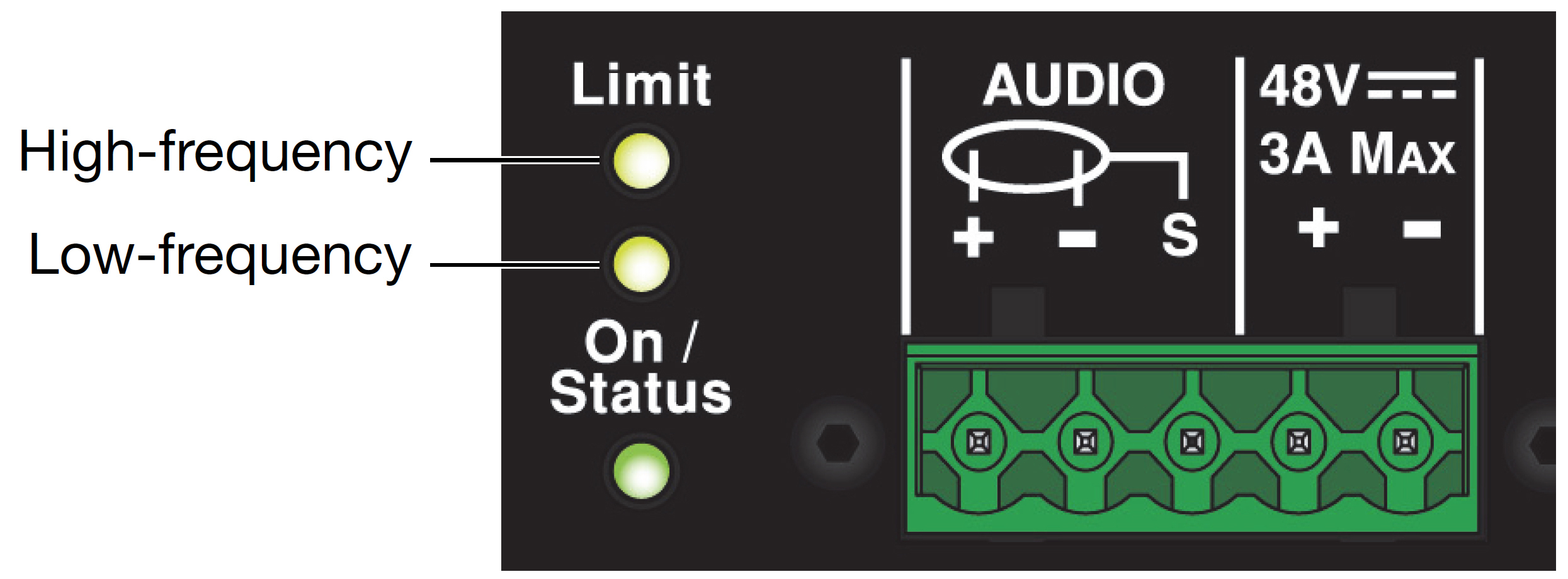
Limit LEDs
Ultra XP loudspeakers perform within their acoustical specifications at normal temperatures when the Limit LEDs are unlit, or when the LEDs are lit for 2 seconds or less and then turn off for at least 1 second. If an LED remains lit for longer than 3 seconds, the loudspeaker enters hard limiting where:
Increases to the input level have no effect.
Distortion increases due to clipping and nonlinear driver operation.
Drivers are subjected to excessive heat and excursion, compromising their lifespan.
Caution
The Limit LEDs indicate when a safe, optimum level has been exceeded. If an Ultra XP loudspeaker begins to limit before reaching the required SPL, consider adding more loudspeakers to the system.
On / status LED
The on / status LED on the user panel indicates whether an Ultra XP loudspeaker is operating normally (green), over-heating (yellow), or clipping (red).
Normal operation (green)
The On/Status LED is green during normal operation, when the loudspeaker is powered on.
Overheating and limiter threshold (yellow)
The On/Status LED turns solid yellow when the loudspeaker’s internal temperature reaches 75° C (167° F), indicating the unit is reaching its maximum heat dissipation.
When the On/Status LED is yellow, a reduction in SPL is recommended. While the loudspeaker will continue to operate while the On/Status LED is yellow, the limiter threshold is lowered by 6 dB (causing the output level to also be reduced) to prevent the loudspeaker from overheating.
When the internal temperature cools to 60° C (140° F), the On/Status LED changes from yellow to green and the limiter threshold returns to normal.
Amplifier Cooling System
Amplifiers for Ultra XP loudspeakers rely solely on natural convection for cooling from air flowing over their heat sinks. The efficient amplifier and heat sink design keeps temperatures low, even when units are operated at high ambient temperatures, in tightly packed configurations, and driven continuously at high output levels.
Caution
The Ultra XP loudspeaker’s heat sink can reach temperatures up to 75° C (167° F) during extreme operation. Use extreme caution when approaching the rear of the loudspeaker.
Clipping on Input (Red)
The On/Status LED turns red when the loudspeaker’s input stage clips. When the On/Status LED is red, the source level should be reduced to avoid distortion and to avoid overloading the amplifier.
Powering ULTRA XP loudspeakers
Ultra XP loudspeakers require an external MPS-488HP IntelligentDC power supply. The single-space 19-inch rack unit distributes DC power and balanced audio to up to eight Ultra XP loudspeakers, or other Meyer Sound IntelligentDC loudspeakers. Composite multiconductor cables, such as Belden 1502 or equivalent, can deliver both DC power and balanced audio to loudspeakers at cable lengths up to 150 feet with just 1 dB of loss in peak SPL using 18 AWG wire. Longer cable runs are possible with heavier gauges. Meyer Sound’s RMS remote monitoring system is optionally available for the MPS-488HP.
Tip
For complete information on using the MPS-488HP IntelligentDC power supply, refer to Legacy.
Power off the MPS-488HP.
Connect audio sources (from a mixer or processor) to the MPS-488HP channel inputs. Use balanced XLR cables.
Use the MPS-488HP Link switches to route channel inputs to channel outputs. For information on the MPS-488HP Link switches, refer to the MPS-488HP Operating Instructions (PN 05.205.005.01).
Connect loudspeakers to the MPS-488HP channel outputs. Use composite cables (such as Belden 1502 or equivalent) wired for both DC power and balanced audio and outfitted with the appropriate connectors.
When connecting loudspeakers equipped with Phoenix connectors to the MPS-488HPp power supply, use Phoenix 5-pin female to Phoenix 5-pin female cables.
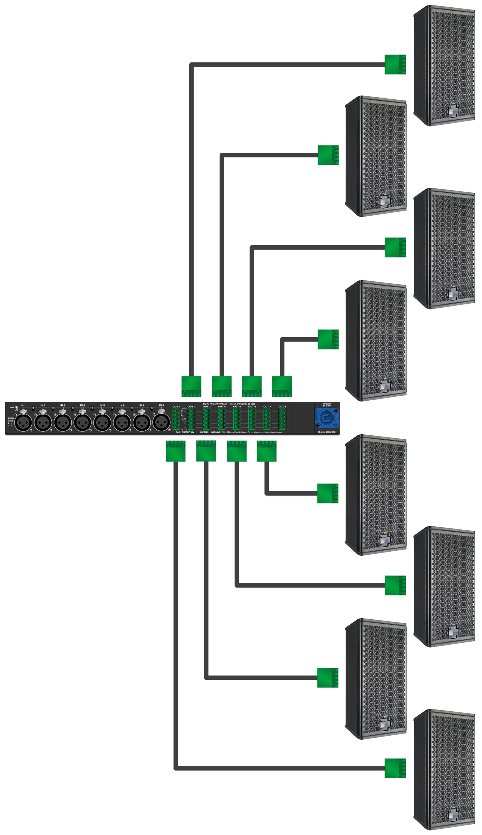
MPS-488HPp with Eight UPJunior-XP Loudspeakers
Tip
You can use two separate cables for loudspeaker connections: a 2-conductor cable for DC power and a 3-conductor cable for balanced audio, both attached to a single Phoenix connector on each cable end. This allows you to use a larger gauge for the DC cable so you can achieve longer cable runs (see Long Cable Runs with Separate Cable for DC Power and Audio).
When connecting loudspeakers equipped with EN3 con- nectors to the MPS-488HPe power supply, use EN3 5-pin male to EN3 5-pin female cables.
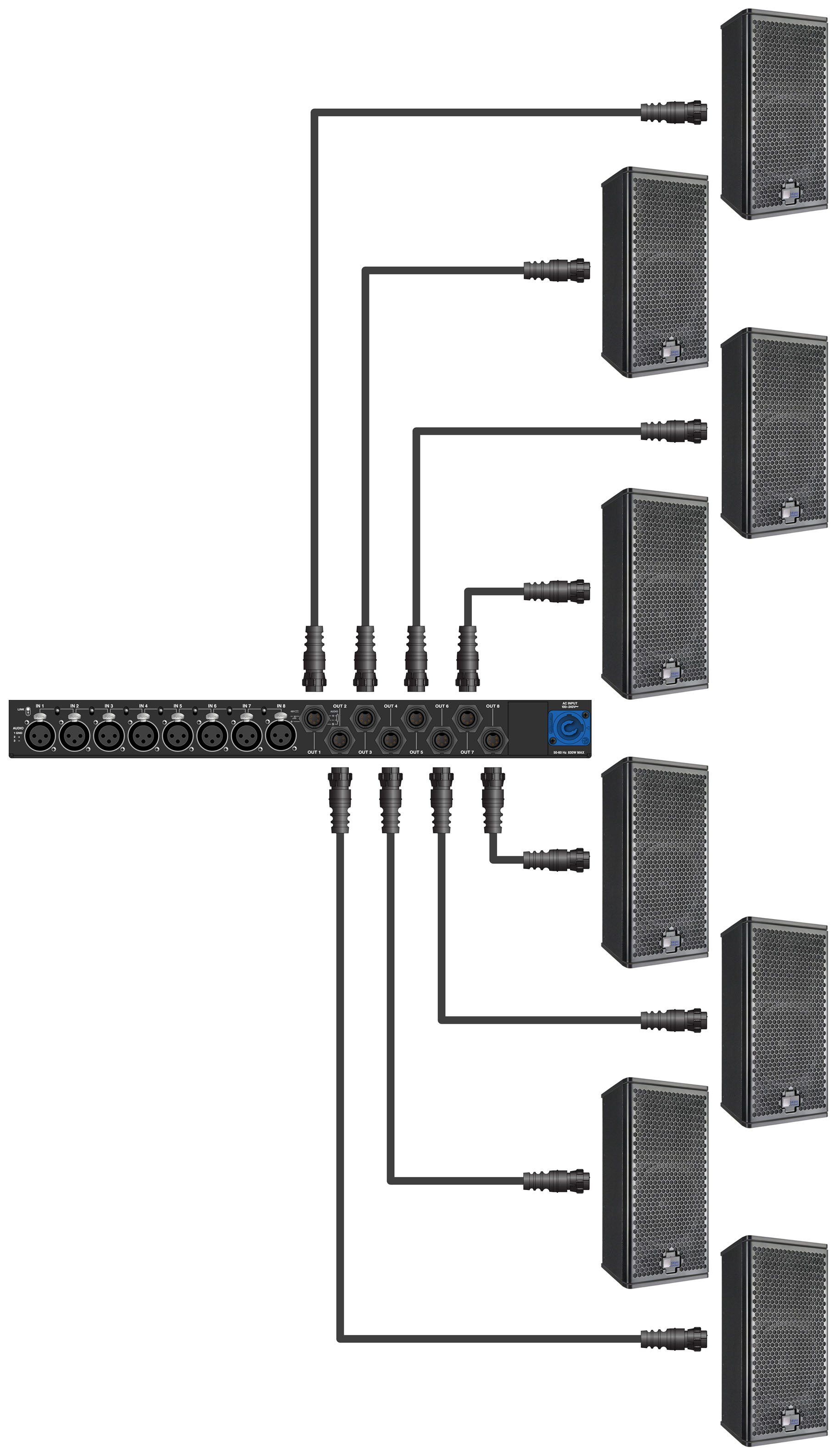
MPS-488HPe with Eight UPJunior-XP Loudspeakers
To join two EN3 cables, one with an EN3 5-pin male cable mount connector to one with an EN3 5-pin female cable mount connector, use an EN3 5-pin female-to-male cable coupler (PN 28.163.033.01).

When connecting loudspeakers equipped with ECO-M connectors to the MPS-488HPp power supply, use Phoenix 5-pin female to ECO-M 7-pin female cables.
Caution
Make sure loudspeaker cables are wired correctly. For details on assembling loudspeaker cables, refer to Assembling Loudspeaker Cables.
Power on the MPS-488HP and monitor the LEDs on the front panel to verify connections. For information on the MPS-488HP LEDs, refer to the MPS-488HP Operating Instructions (PN 05.205.005.01).
Check the On/Status LEDs on the loudspeaker rear user panels and verify they are green (ready to reproduce audio).
Enable output from the audio sources (from the mixer or processor) connected to the MPS-488HP.
Mounting Ultra XP loudspeakers
Important safety considerations
When installing Meyer Sound loudspeakers, always observe the following precautions:
Use all Meyer Sound products in accordance with local, state, federal, and industry regulations. Owners and users must evaluate the reliability of any rigging or mounting method for their application. Rigging loudspeakers requires trained and experienced professionals.
Use mounting and rigging hardware rated to meet or exceed the suspended weight.
Make sure to attach mounting hardware to the building's structural components (studs or joists), and not just to the wall surface. Verify that the building's structure and the anchors used for the installation will safely support the total weight of the mounted loudspeakers.
Use mounting hardware appropriate for the installation surface.
Tighten bolts securely. Meyer Sound recommends using Loctite® on bolt threads and safety cables.
Inspect mounting and rigging hardware regularly. Immediately replace any worn or damaged components.
ULTRA XP loudspeaker rigging options
Loudspeaker | Rigging |
|---|---|
UPJ-1XP ultracompact VariO loudspeaker | Heavy-duty, corrosion-resistant 6061-T6 aluminum end plates with threaded M8 attachment points for QuickFly rigging options, basic eyebolt rigging, and third-party pole assemblies |
UPJunior-XP ultracompact VariO loudspeaker | Heavy-duty, corrosion-resistant 6061-T6 aluminum end plates with threaded M8 attachment points for QuickFly rigging options, basic eyebolt rigging, and third-party pole assemblies |
UPM-1XP ultracompact wide coverage loudspeaker | Three 3/8”-16 or metric M10 nut plates |
UPM-2XP ultracompact nar- row coverage loudspeaker | Three 3/8”-16 or metric M10 nut plates |
UMS-1XP ultracompact subwoofer | Pole-mount receptacle; cabinet optionally available (UMS-SM subwoofer) with factory installed threaded end plates for single-mount configurations with the UMS-SM U-bracket |
Note
The UMS-SM subwoofer is a version of the UMS-1XP subwoofer with threaded end lates for single-mount configurations with the UMS-SM U-bracket. The UMS-SM end plates are factory-installed with the U-bracket and not available as an upgrade option for the UMS-1XP.
U-brackets
The following U-brackets are available for Ultra XP loudspeakers. All Ultra XP U-brackets can be mounted on walls and ceilings (under balcony and canopy areas), while some can also be mounted on floors (for stage monitoring and frontfill applications), trusses, and poles. The MUB-UPM U-bracket includes a single loudspeaker attachment point with a fixed mounting distance from the surface; the MUB-UPJ and MUB-UPJunior U-brackets include adjustable slots for variable mounting distances from the surface; the UMS-SM U-bracket includes two loudspeaker attachment points. The MUB-UPJ and MUB-UPJunior U-brackets can fly multiple cabinets with the use of array adapters (for more information, see Array Adapters for UPJ-1XP and UPJunior-XP).
Model | Supported Loudspeakers | Maximum Number of Cabinets | Loudspeaker Attachment | Mounting Options/Notes |
|---|---|---|---|---|
MUB-UPJ (PN 40.134.081.01) | UPJ-1P UPJ-1XP |
| Adjustable slot |
(2) 1/4” center holes
|
MUB-UPJunior (PN 40.173.110.01) | UPJunior UPJunior-XP |
| Adjustable slot |
(2) 1/4” center holes
|
MUB-UPM 3/8”-16 (PN 40.066.040.01), | UPM-1P, UPM-2P, UPM-1XP, UPM-2XP | 1 | Single fixed attachment point |
|
MUB-UPM M10 (PN 40.066.040.02) | UPM-1P, UPM-2P, UPM-1XP, UPM-2XP | 1 | Singled fixed attachment point |
|
UMS-SM (PN 40.086.110.01) | UMS-1P SM, UMS-1XP SM | 1 | Two fixed attach- ment points |
|
Caution
The (2) 1/4” center holes on the MUB-UPJ and MUB-UPJunior U-brackets should only be used for securing the bracket to pole-mount adapters. These holes are not rated for flying loudspeakers.
Note
The UMS-1XP SM subwoofer includes threaded end plates for single-mount configurations with the UMS-SM U-bracket. The UMS-1XP SM end plates are factory-installed with the U-bracket and not available as an upgrade option for the UMS-1XP.
Mounting yokes
The following mounting yokes are available for the UPJ-1XP, UPJunior-XP, UPM-1XP, and UPM-2XP loudspeakers. The yokes suspend a single loudspeaker and allow a wide range of horizontal and vertical adjustment. The yokes for the UPJ-1XP and UPJunior-XP attach to the bottom end plate. The yokes for the UPM-1XP and UPM-2XP attach to the top and bottom nut plates and include both 3/8”-16 and M10 hardware. A “C” or “G” hanging clamp and steel safety cable (not included) are required to suspend the loudspeakers with yokes.
Model | Supported Loudspeakers | Maximum Number of Cabinets | Loudspeaker Attachment | Mounting Options/Notes |
|---|---|---|---|---|
MYA-UPJ (PN 40.134.035.01) | UPJ-1P UPJ-1XP | 1 | Bottom |
|
MYA-UPJunior (PN 40.173.044.01) | UPJunior UPJunior-XP | 1 | Bottom |
|
MYA-UPM (PN 40.084.038.01) | UPM-1P, UPM-2P, UPM-1XP, UPM-2XP | 1 | Top/Bottom |
|
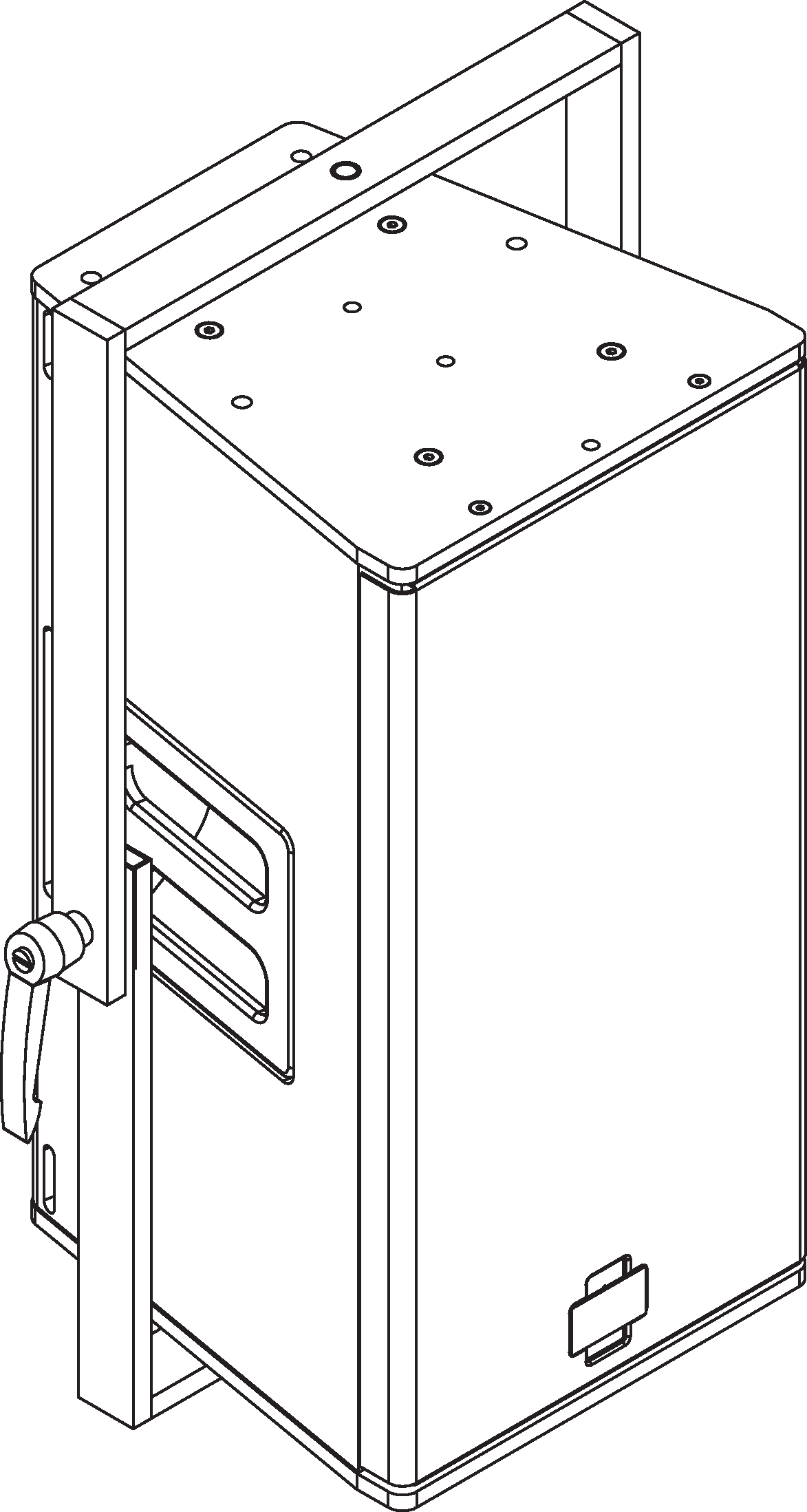
MYA-UPJ Mounting Yoke
MYA-UPJunior Mounting Yoke
MYA-UPM Mounting Yoke
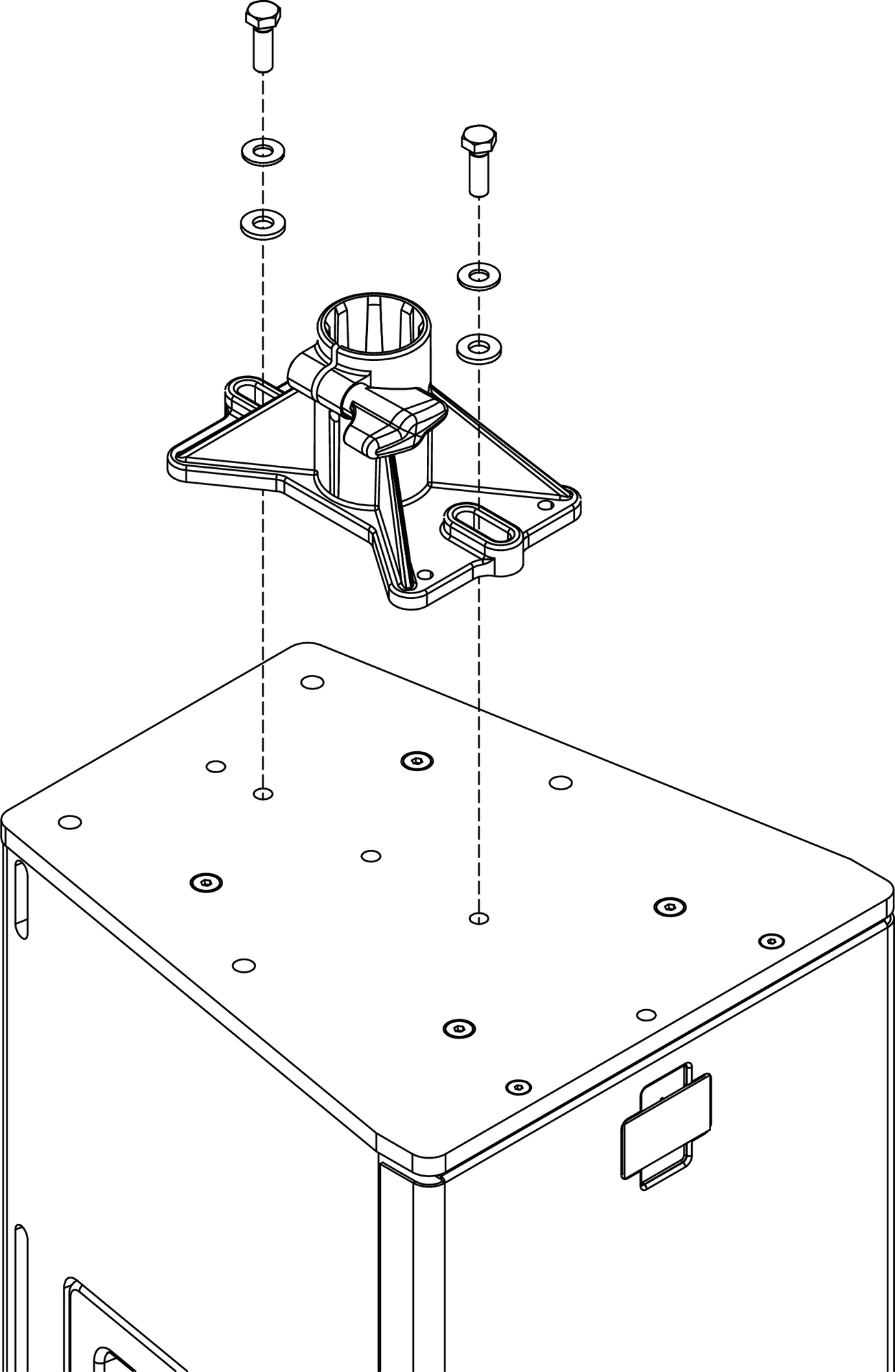
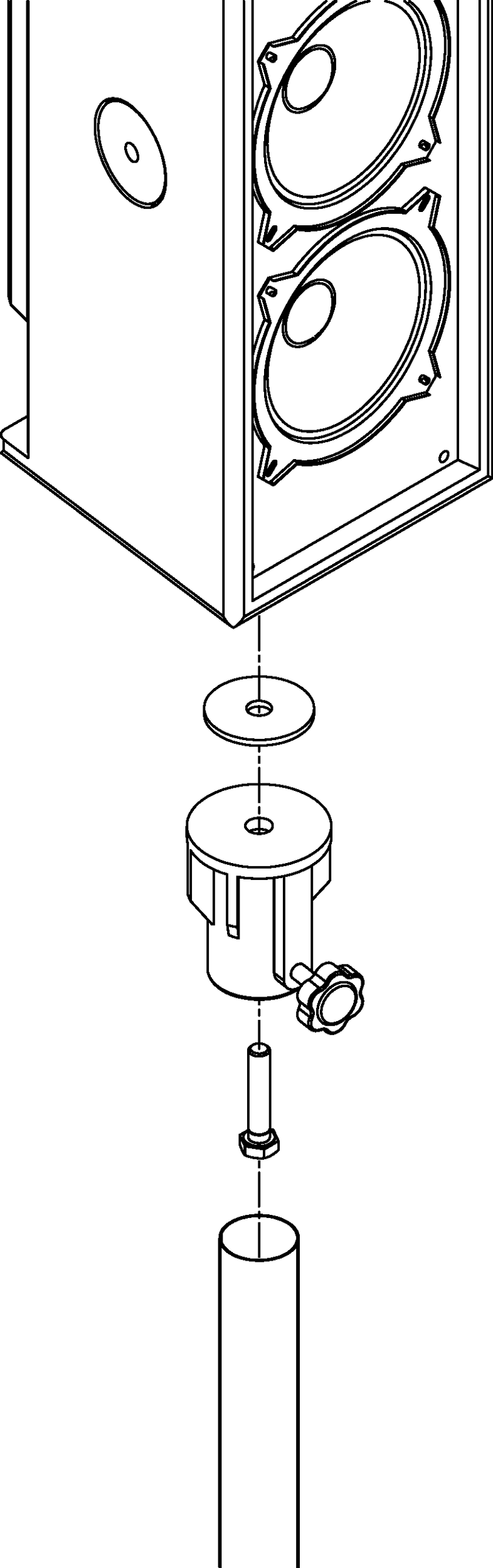
Poles and pole-mount adapters
The following poles and pole-mount adapters are available for Ultra XP loudspeakers. The MSA-UPM pole-mount adapter mounts a single UPM-1XP or UPM-2XP loudspeaker. The (third-party) Ultimate Support BMB-200K pole-mount adapter mounts a single UPJ-1XP or UPJunior-XP loudspeaker; it can also mount two cabinets with a U-bracket and array adapter kit (see U-brackets. The MPS-UMS pole allows a single Ultra XP loudspeaker to be mounted above the UMS-1XP subwoofer, as shown in the second figure below).
Model | Supported Loudspeakers | Maximum Number of Cabinets | Loudspeaker Attachment | Mounting Options/Notes |
|---|---|---|---|---|
Ultimate Support BMB-200K Pole-Mount Adapter (Third Party) | UPJ-1P, UPJunior, UPJ-1XP, UPJunior-XP | 2 | Bottom |
|
MSA-UPM Pole-Mount Adapter (PN 40.086.013.01) | UPM-1P, UPM-2P, UPM-1XP, UPM-2XP | 1 | Bottom |
|
MPS-UMS Pole (PN 40.086.014.02) | UMS-1P, UMS-1XP | 1 | Top (pole-mount receptacle) |
|
MPK-UMS Pole-Mount Kit (PN 40.086.014.01) | UPM-1P, UPM-2P, UPM-1XP, UPM-2XP UMS-1P, UMS-1XP | 1 | – |
|
Caution
When pole-mounting Ultra XP loudspeakers with third-party hardware, make sure the pole and pole-mount adapter have been rated to support the total weight of the loudspeaker. Observe all safety precautions specified by the manufacturer.
Ultimate Support BMB-200K Pole-Mount Adapter with UPJ-1XP
MSA-UPM Pole-Mount Adapter with UPM-1XP
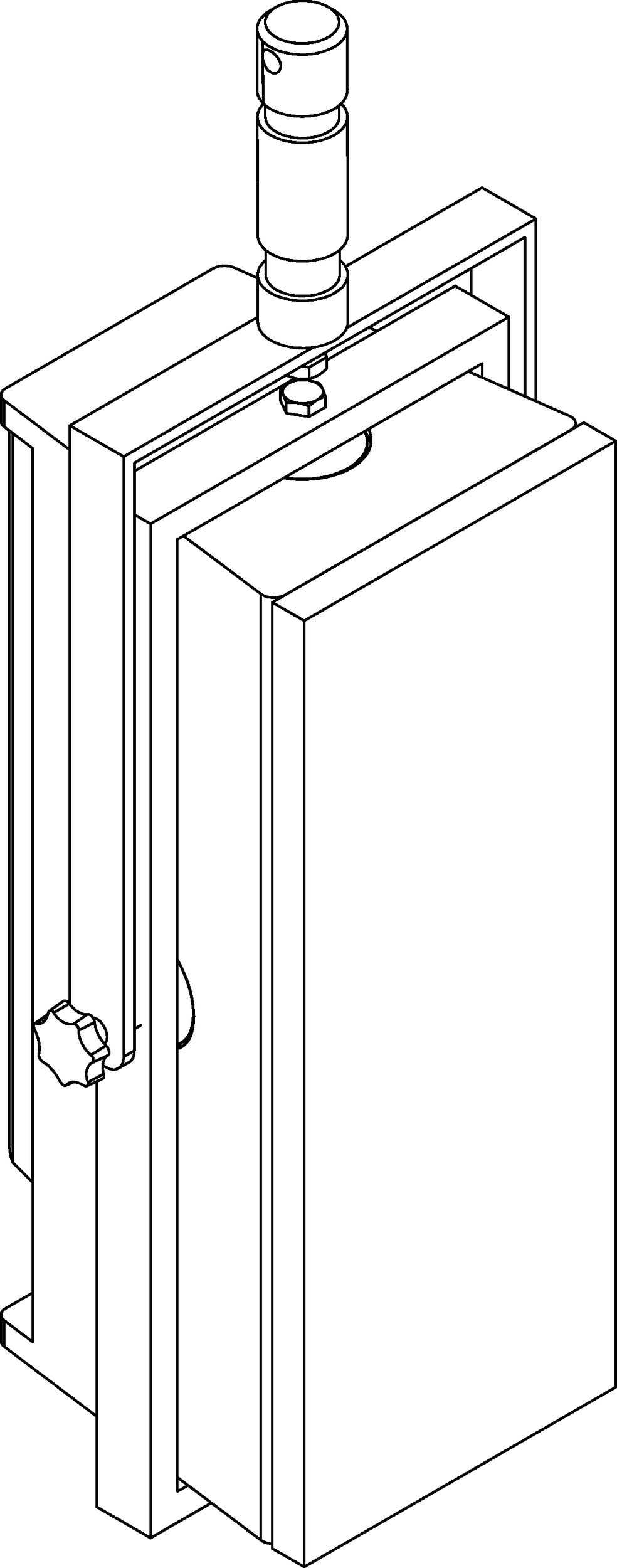
With the appropriate pole and pole-mount hardware, the UPJ-1XP, UPJunior-XP, UPM-1XP, and UPM-2XP can be mounted above the UMS-1XP subwoofer.
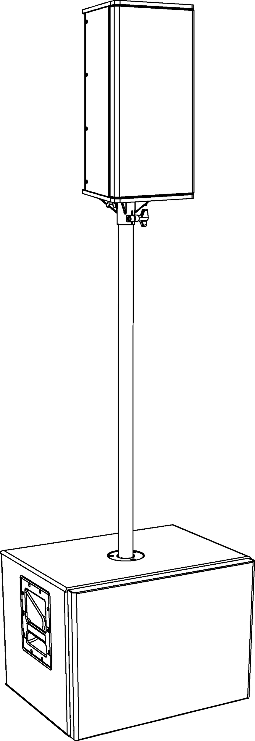
UMS-1XP with MPS-UMS Pole and UPJunior-XP
Eyebolt rigging for UPJ-1XP and UPJunior-XP
The UPJ-1XP and UPJunior-XP ship with two M8 threaded, 20 mm eyebolts. The eyebolts attach to the top or bottom end plates and can be used to suspend the loudspeaker.
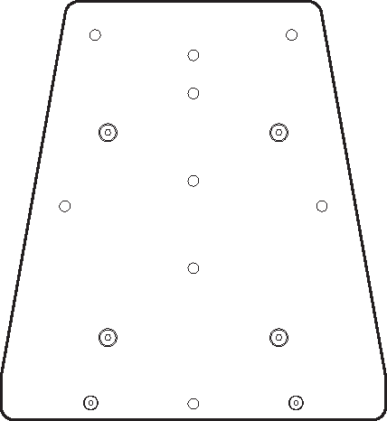
Ultra XP Top Plate with Threaded Holes for Eyebolts
A single loudspeaker can be suspended with one eyebolt. However, two eyebolts provide more safety and stability, as well as the capability of aiming and tilting the loudspeaker for targeted coverage.
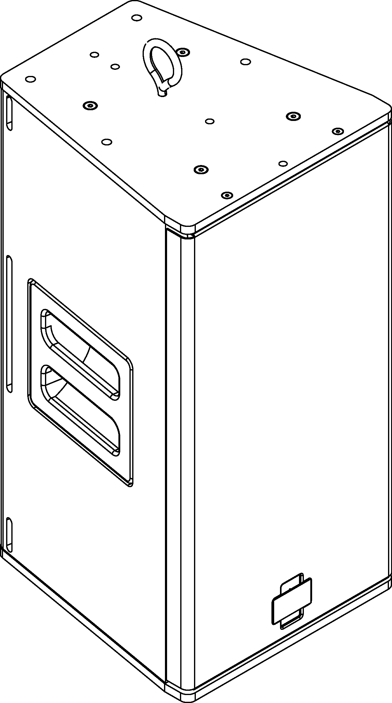
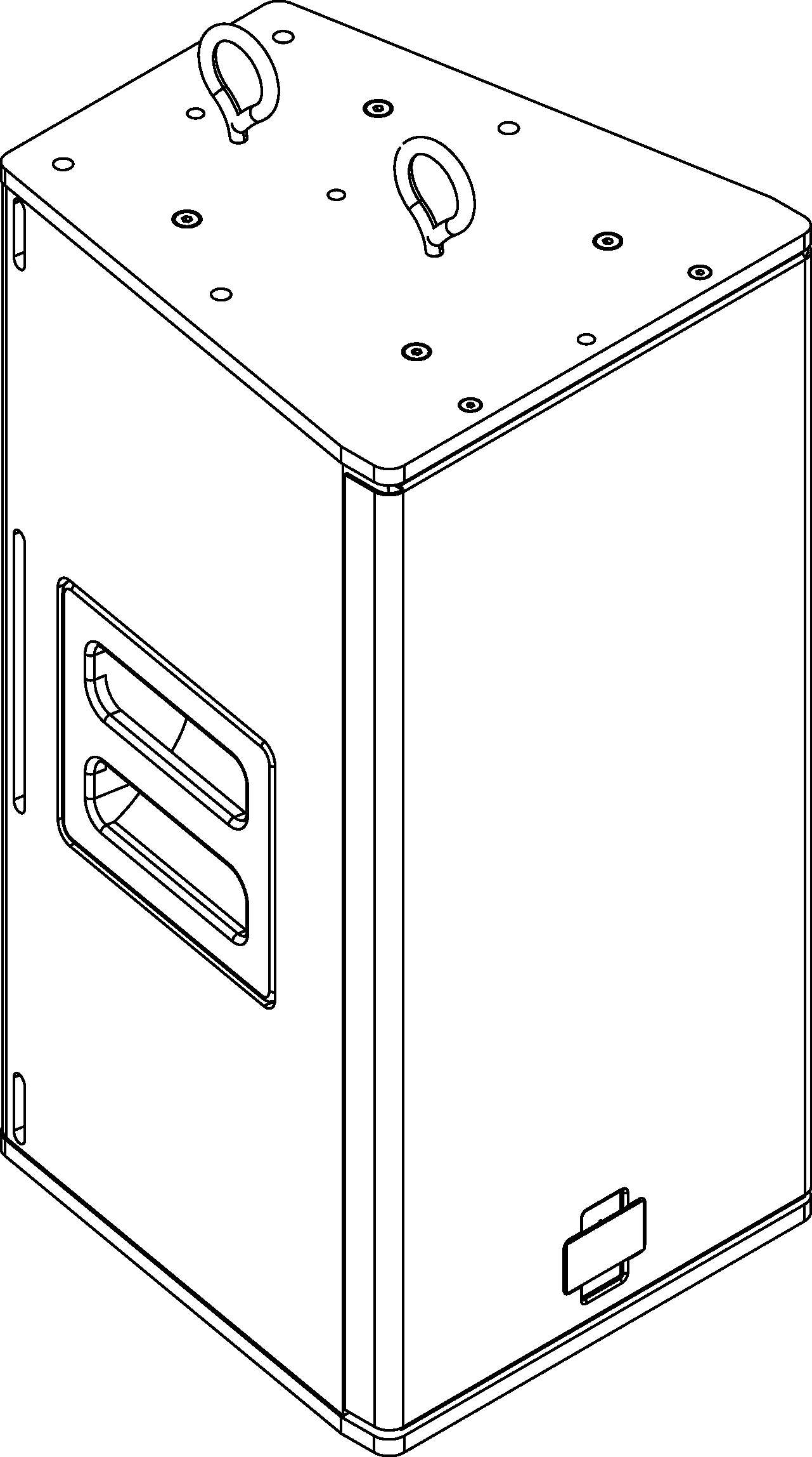
Ultra XP with One Eyebolt (Left) and Two Eyebolts (Right)UMS-1XP with MPS-UMS Pole and UPJunior-XP
Note
Up to two UPJ-1XPs UPJunior-XPs, oriented vertically, can be suspended with the eyebolts supplied by Meyer Sound at a 7:1 safety factor. For this configuration, the top loudspeaker would have two eyebolts installed on its top plate and two eyebolts installed on its bottom plate, for connecting to the second loudspeaker. Additional M8 eyebolts are available from Meyer Sound.
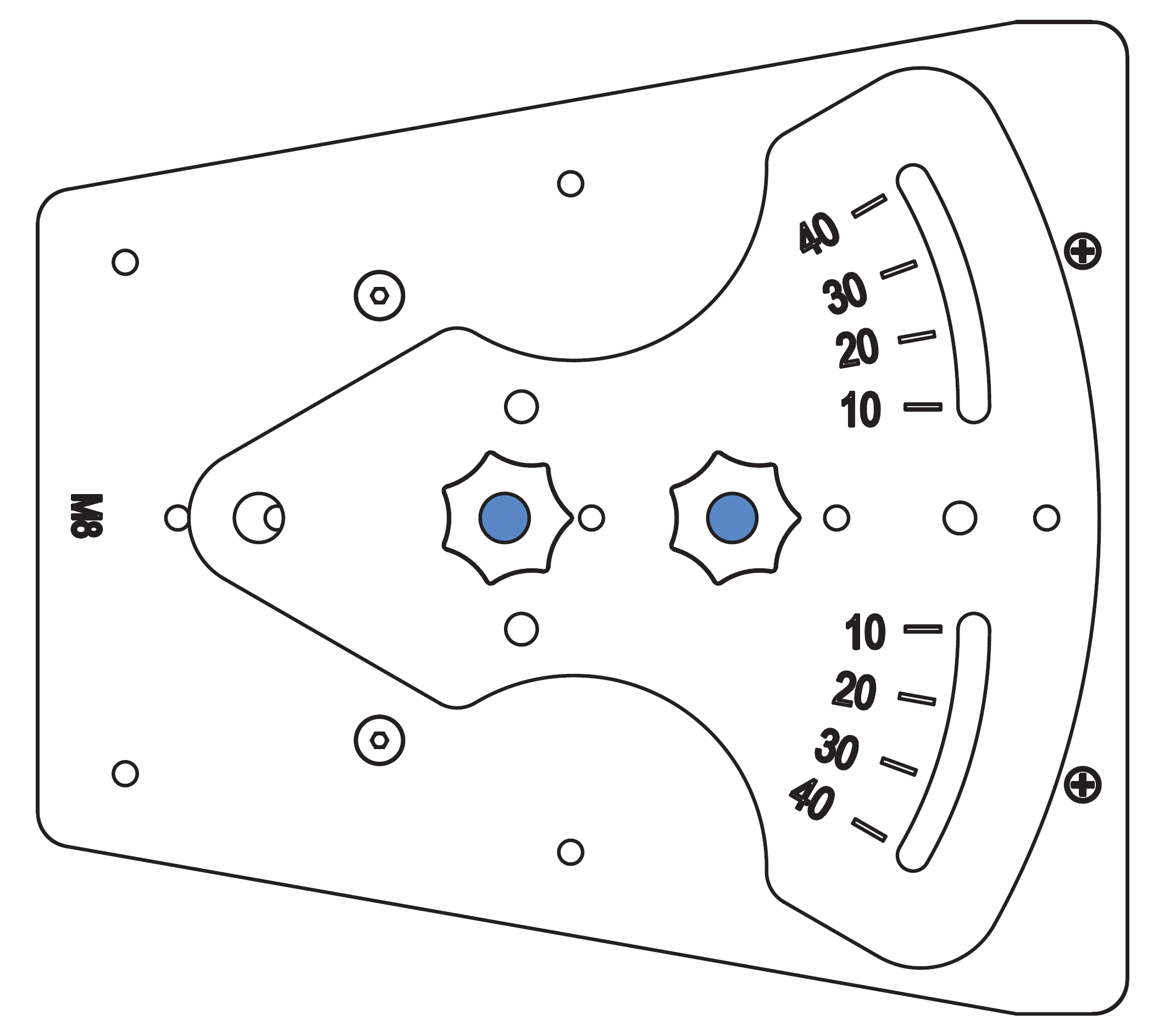
Array adapters for UPJ-1XP and UPJunior-XP
Array adapter plates are available for the UPJ-1XP (MAAM-UPJ) and UPJunior-XP (MAAM-UPJunior) to form horizontal and vertical arrays of up to three loudspeakers.
The front adjustment slot is used to adjust the distance between the loudspeakers to achieve splay angles from 20 to 80 degrees. The array adapter kits include two array adapter plates, eight M8 screws and washers, and four M8 knobs (for floor monitor use only). A single kit can array two UPJ-1XPs or two UPJunior-XPs; two kits are required for an array of three loudspeakers.
Caution
The MAAM-UPJ array adapter supports a maximum of three UPJ-1XP loudspeakers in an array.
The MAAM-UPJunior array adapter supports a maximum of three UPJunior-XP loudspeakers in an array.
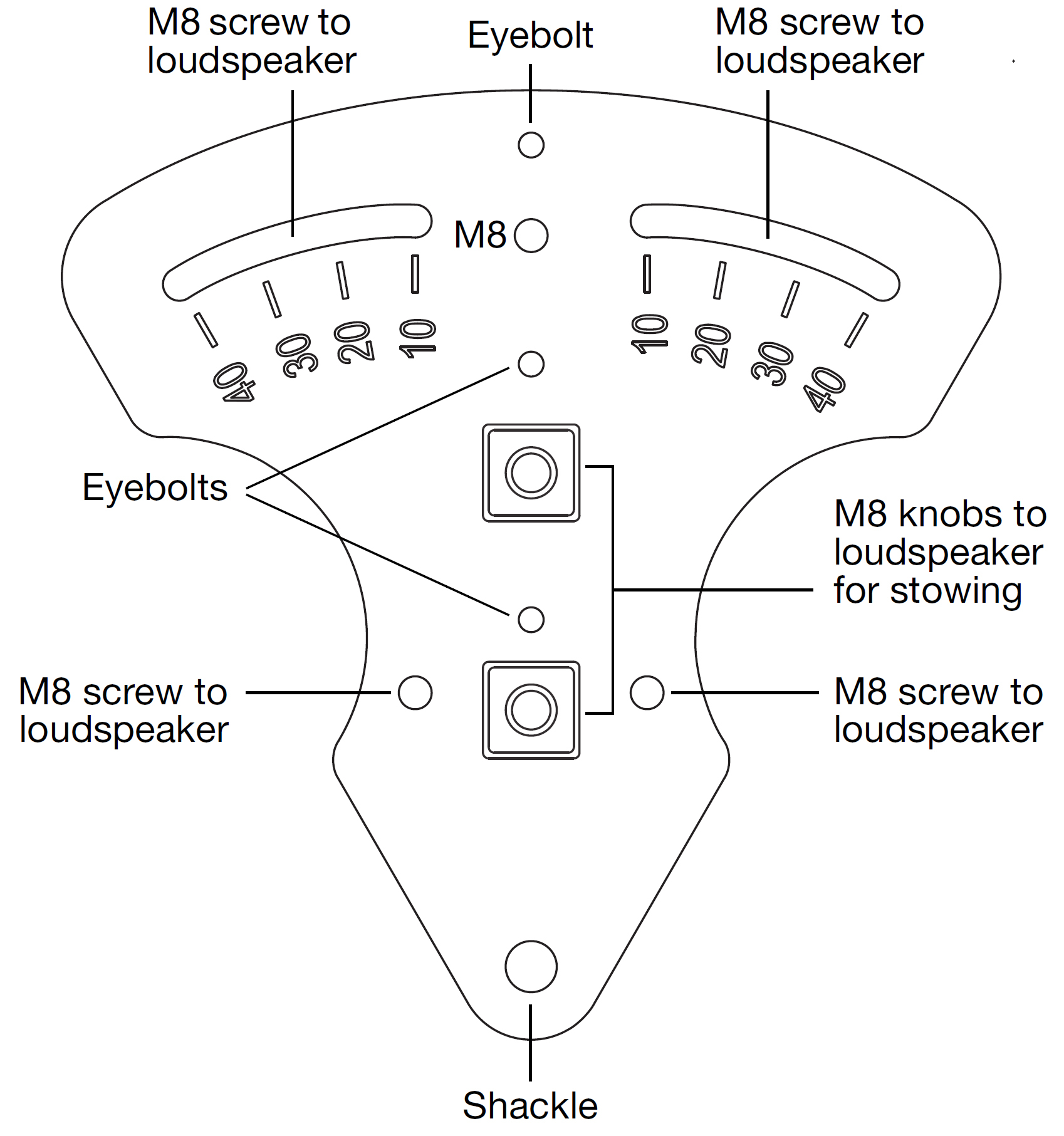
MAAM-UPJ Array Adapter Plate (for UPJ-1XP Loudspeakers)
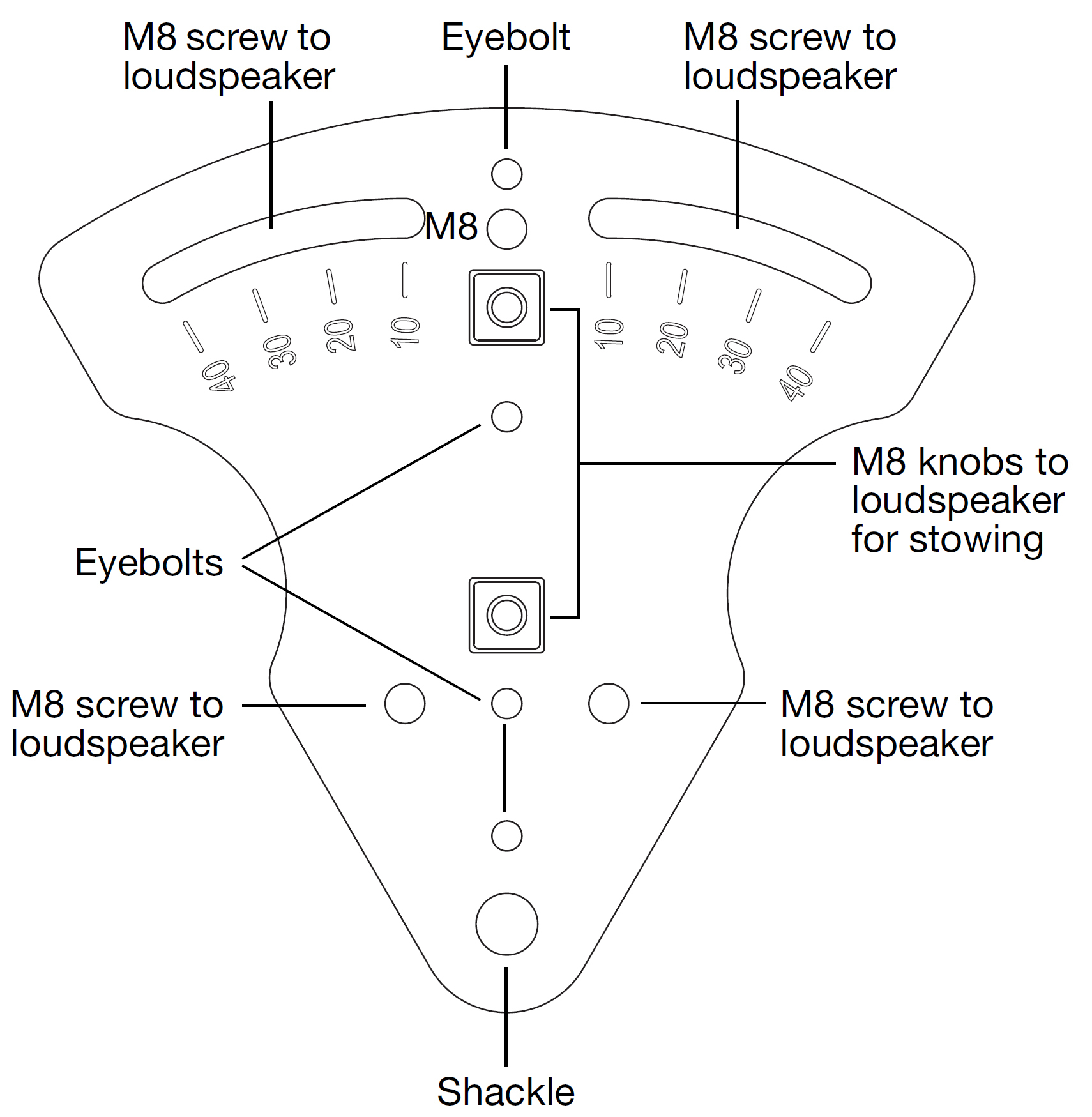
MAAM-UPJunior Array Adapter Plate (for UPJunior-XP Loudspeakers)
Arrays are assembled by attaching the array adapter plates to the top and bottom end plates of the loudspeakers and securing them with the included M8 screws and washers.
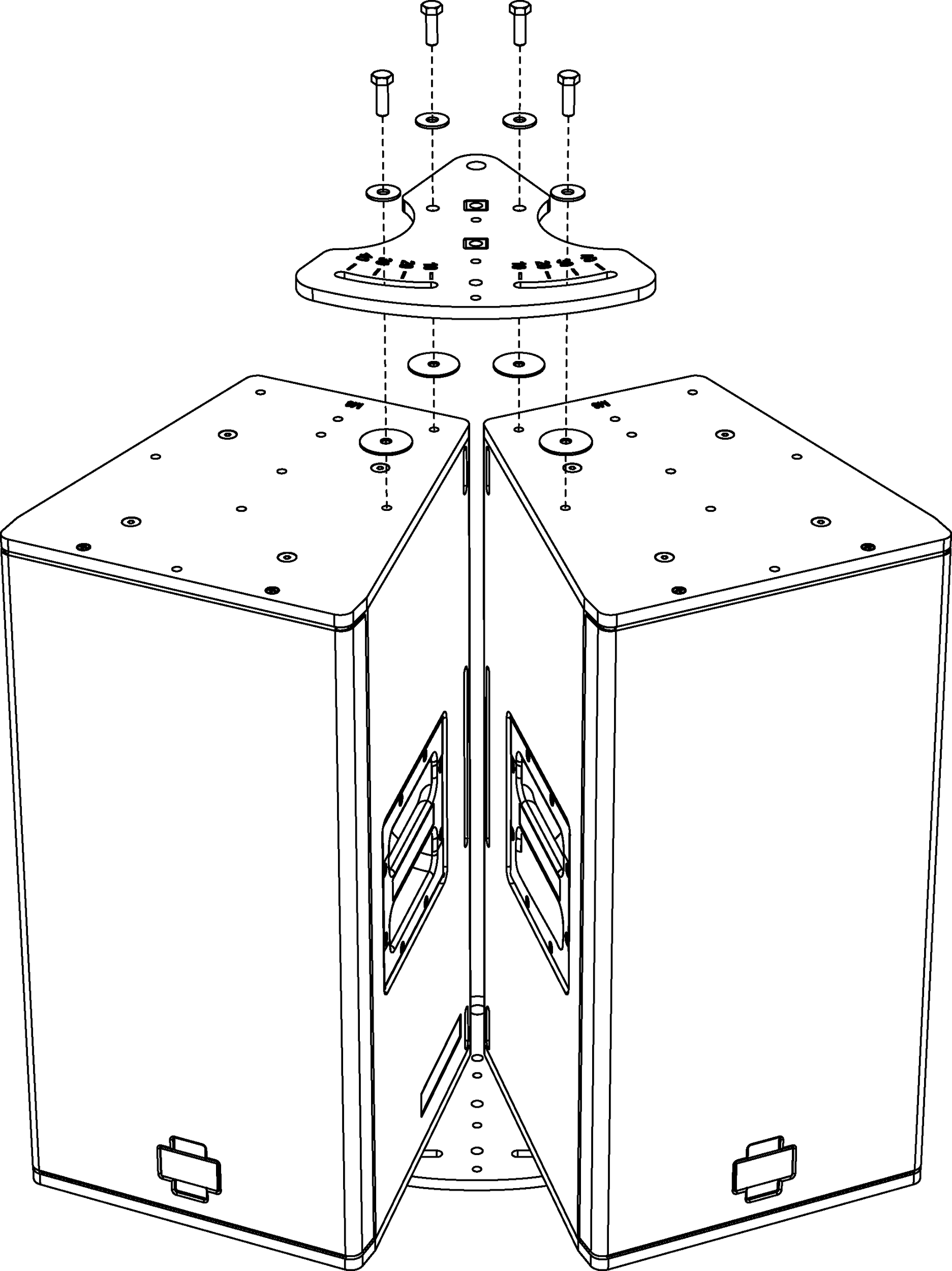
MAAM-UPJ with UPJ-1XPs, Exploded View
Array adapters can also be used to position UPJ-1XPs and UPJunior-XPs as floor monitors with adjustable angles.
When positioning the loudspeakers as floor monitors, the array adapter plates attach to the loudspeakers with the included M8 knobs.
Caution
The M8 knobs included with array adapters should only be used to secure the plates to the loudspeakers when positioning them as floor monitors. The M8 knobs should not be used for flown applications.
Horizontal arrays
Horizontal arrays with the array adapter can be flown by attaching eyebolts to the loudspeaker end plates or directly to the array adapter plates. Shackles can also be attached to the adapter plate’s rear pickup holes for additional support or to provide control over the array’s vertical tilt.
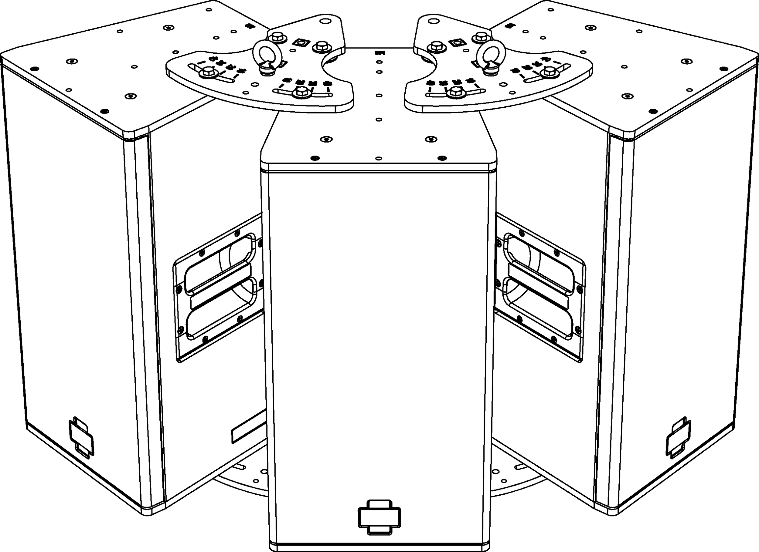
MAAM-UPJ with UPJ-1XP Horizontal Array and Eyebolts
Tip
To create optimum coverage in horizontal arrays, the splay angles between loudspeakers should be 50 degrees when the VariO horns are in the 80-degree horizontal by 50-degree vertical position (this yields a horizontal coverage of 130 degrees).
Angles less than 50 degrees between loudspeakers can cause too much interaction between the loudspeakers, while angles greater than 50 degrees can yield holes in the coverage.
Vertical arrays
Vertical arrays with the array adapter can be flown by attaching eyebolts to the loudspeaker end plates or directly to the array adapter plates. Shackles can also be attached to the adapter plate’s rear pickup holes for additional support or to provide control over the vertical tilt.
MAAM-UPJ, Vertical Array with Eyebolts
Vertical arrays of up to three loudspeakers with the array adapter can be ceiling-mounted by attaching a U-bracket to the top loudspeaker.
MAAM-UPJ, Vertical Array Ceiling-Mounted
Note
When flying an array of UPJ-1XPs from the MUB-UPJ U-bracket, the bracket should be fastened to the holes toward the rear of the loudspeaker plates to compensate for the shift in center of gravity. In addition, shackles can be attached to the array adapter plate’s rear pickup holes for additional support or to provide control over the vertical tilt.
Tip
To create optimum coverage in vertical arrays, the splay angles between loudspeakers should be 30 degrees when the VariO horns are in the 80-degree horizontal by 50-degree vertical position (this yields a vertical coverage of 80 degrees). Angles less than 30 degrees between loudspeakers can cause too much interaction between the loudspeakers, while angles greater than 30 degrees can yield holes in the coverage.
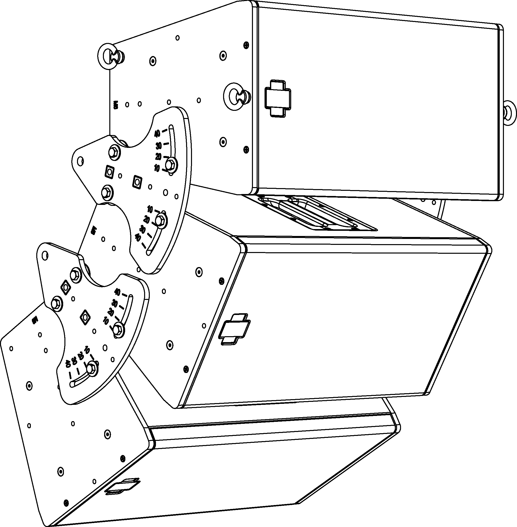
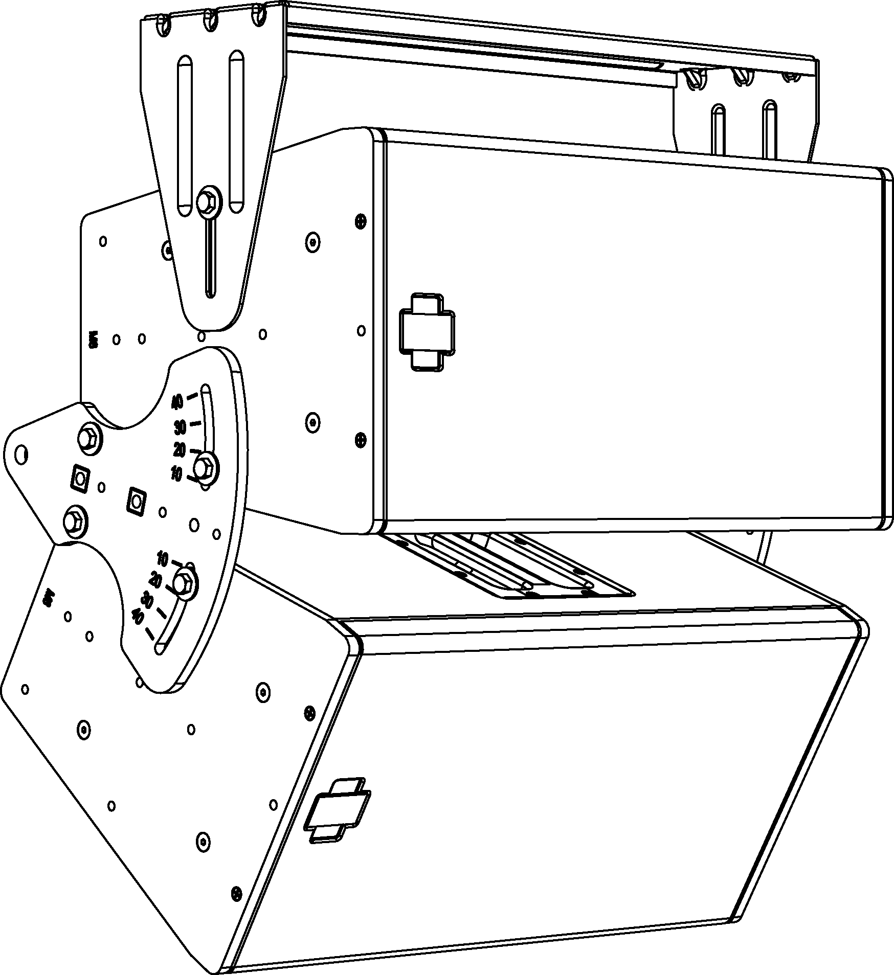
Floor monitoring with array adapters
The array adapters can be used to position the UPJ-1XP and UPJunior-XP loudspeakers as floor monitors with the front adjustment slot being used to adjust the angle of the loudspeaker. The following illustrations show the stowed position, for when the loudspeaker is not in use (shown in the first figure below), as well as some of the more common angle configurations.
MAAM-UPJ and M8 knobs stowed with UPJ-1XP
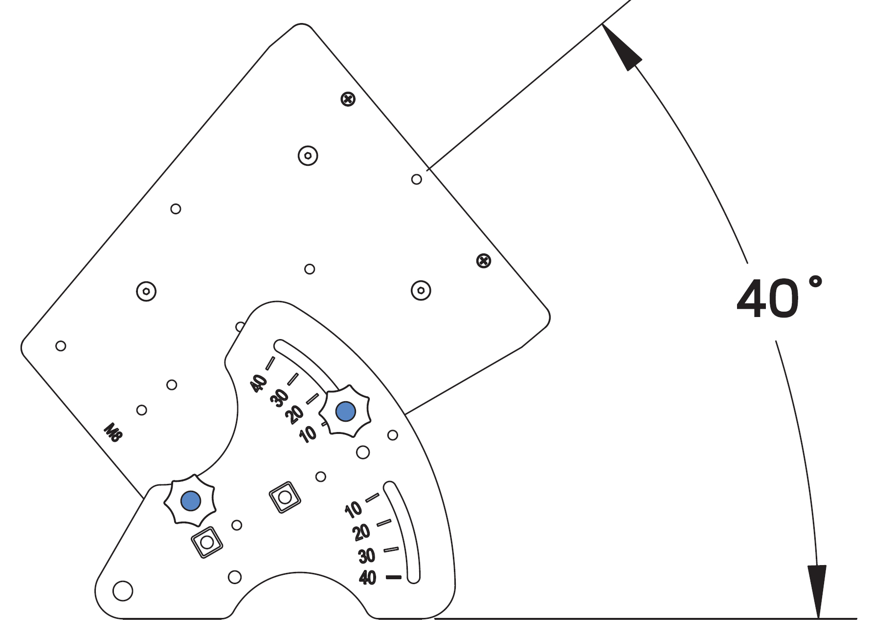
MAAM-UPJ with UPJ-1XP at 40 Degrees
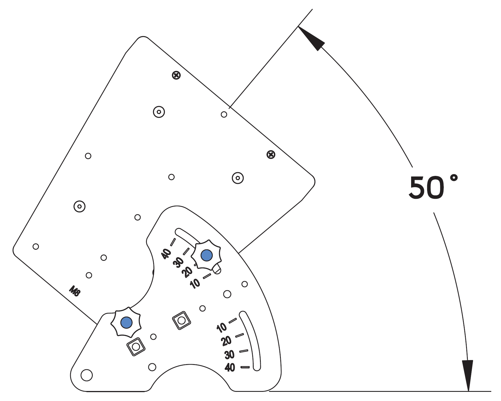
MAAM-UPJ with UPJ-1XP at 50 Degrees
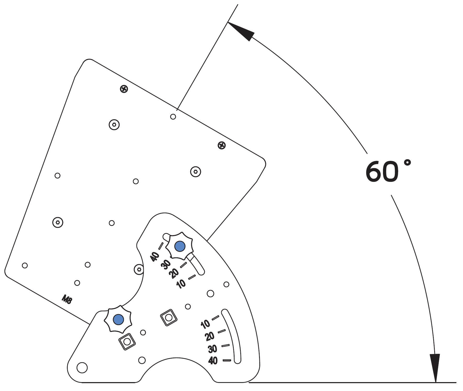
MAAM-UPJ with UPJ-1XP at 60 Degrees
ULTRA XP accessories
Cable connectors and adapters
The following cable connectors and adapters are available from Meyer Sound.
Part Number | Connector/Adapter | Use |
|---|---|---|
484.065 | Phoenix 5-pin female cable mount connector | Connects to MPS-488HPp channel outputs and loudspeakers equipped with Phoenix 5-pin male panel mount connectors |
468.069 | EN3 5-pin female cable mount connector | Connects to loudspeakers equipped with EN3 5-pin male panel mount connectors |
468.071 | EN3 5-pin male cable mount connector | Connects to MPS-488HPe channel outputs |
468.072 | EN3 5-pin female inline cable adapter | Connects to EN3 5-pin male cable mount connectors for assembling extension cables |
468.073 | EN3 5-pin male inline cable adapter | Connects to EN3 5-pin female cable mount connectors for assembling extension cables |
468.081 | ECOM 7-pin female cable mount connector | Connects to loudspeakers equipped with ECOM 7-pin male panel mount connectors |
28.163.033.01 | Cable coupler EN3 5-pin female-to-male (5-inch, 0.12 m) | Joins two cables: one with an EN3 5-pin male cable mount connector to one with an EN3 5-pin female cable mount connector |
Loudspeaker cables
The following loudspeaker cables are available from Meyer Sound and can be used to connect Ultra XP loudspeakers to Meyer Sound Intelligent DC power supplies.
Note
Phoenix and EN3 loudspeaker cables and bulk cable use Belden 1502R (regular) or Belden 1502P (plenum) cable. Belden 1502 is a composite cable comprised of two 18 AWG wires for DC power, two 22 AWG wires for balanced audio, and one 24 AWG wire for audio shield.
Part Number | Cable | Color | Coating | Length |
|---|---|---|---|---|
524.014 | Bulk (no connectors) | Black | Regular | 500 ft spool |
524.015 | Bulk (no connectors) | White | Plenum | 500 ft spool |
28.163.009.01 | EN3 5-pin female to pigtail | Black | Regular | 10 ft |
28.163.009.11 | EN3 5-pin female to pigtail | White | Plenum | 10 ft |
28.163.009.21 | EN3 5-pin female to EN3 5-pin male | Black | Regular | 10 ft |
28.163.009.22 | 20 ft | |||
28.163.009.23 | 30 ft | |||
28.163.009.24 | 50 ft | |||
28.163.009.25 | 100 ft | |||
28.163.009.26 | 150 ft |
Part Number | Cable | Color | Coating | Length |
|---|---|---|---|---|
28.163.009.31 | EN3 5-pin female to EN3 5-pin male | White | Plenum | 10 ft |
28.163.009.32 | 20 ft | |||
28.163.009.33 | 30 ft | |||
28.163.009.34 | 50 ft | |||
28.163.009.35 | 100 ft | |||
28.163.009.36 | 150 ft | |||
28.163.009.41 | EN3 5-pin female to Phoenix 5-pin female | Black | Regular | 10 ft |
28.163.009.42 | 20 ft | |||
28.163.009.43 | 30 ft | |||
28.163.009.44 | 50 ft | |||
28.163.009.45 | 100 ft | |||
28.163.009.46 | 150 ft | |||
28.163.009.51 | EN3 5-pin female to Phoenix 5-pin female | White | Plenum | 10 ft |
28.163.009.52 | 20 ft | |||
28.163.009.53 | 30 ft | |||
28.163.009.54 | 50 ft | |||
28.163.009.55 | 100 ft | |||
28.163.009.56 | 150 ft |
Rain hoods
The following rain hoods are available from Meyer Sound.
Part Number | Rain Hood | Use |
|---|---|---|
40.196.062.01 | Horizontal Rain Hood | To be used with horizontally oriented Ultra XP loudspeakers: UPJ-1XP, UPJunior-XP, UPM-1XP, UPM-2XP, UMS-1XP |
40.196.062.02 | Vertical Rain Hood | To be used with vertically oriented Ultra XP loudspeakers: UPJ-1XP, UPJunior-XP, UPM-1XP, UPM-2XP, UMS-1XP |
40.196.062.03 | Reversed Rain Hood | To be used with weather-protected UPM-1XP and UPM-2XP loudspeakers |
Caution
When wiring Ultra XP loudspeaker cables, it is extremely important that each pin be wired correctly. Make sure the 48 V DC from the external power supply is wired directly (and only) to the 48 V DC pins on the Ultra XP loudspeaker connector, and that the polarity is observed (negative to negative, positive to positive) to avoid damage to the loudspeaker. In addition, make sure that audio pins are wired correctly; polarity reversals for audio signals affect system performance.
Assemble IntelligentDC loudspeaker cables
When wiring IntelligentDC loudspeaker cables, each pin in the cable must align correctly with the corresponding pin in the MPS channel output connector (see Channel Outputs). Ensure the 48 V DC from the MPS power supply connects directly (and only) to the 48 V DC pins on the loudspeaker connector, and that the polarity aligns (negative to negative, positive to positive) to prevent damage to the loudspeaker. In addition, verify the audio pin polarity, as reversals in audio signals can affect system performance.
Wire | Gauge | Signal |
|---|---|---|
Red | 18 AWG | DC power, positive (+) |
Black | 18 AWG | DC power, negative (–) |
White | 22 AWG | balanced audio, positive (+) |
Blue | 22 AWG | balanced audio, negative (–) |
Shield | 24 AWG | balanced audio, shield |
Assembling Phoenix-to-Phoenix Loudspeaker Cables
When connecting loudspeakers equipped with Phoenix connectors to the MPS-488HPp power supply, you need a Phoenix 5-pin female to Phoenix 5-pin female cable. The following procedure documents how to assemble this cable.
 |
Assembled Phoenix-to-Phoenix Cable
If the cable has not yet been stripped, strip one end of the cable. Strip the outer shielding by 1 inch and then strip the black, red, blue, and white wires by 0.275 inch.

Insert the five exposed conductors into the five cable holes in a Phoenix 5-pin female cable mount connector. Use the following wiring scheme.

Pin Destinations for Phoenix 5-Pin Female Cable Mount Connector
Secure the conductors by tightening the five screws in the Phoenix cable mount connector. Screws should be torqued to 5–6 Nm(4.4–5.3 In-Lbs).

Caution
Screws should not be inserted into the Phoenix connector while the connector rests in a mating plug. Doing so will damage the contacts. During assembly, the Phoenix connector should only be held in place externally.
Repeat the previous steps and attach the other end of the cable to another Phoenix 5-pin female cable mount connector.
Verify the wiring polarity is correct for both cable ends
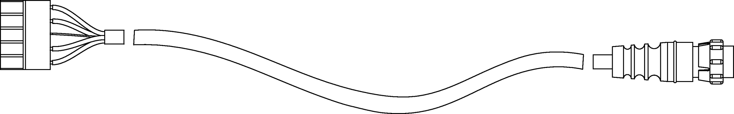
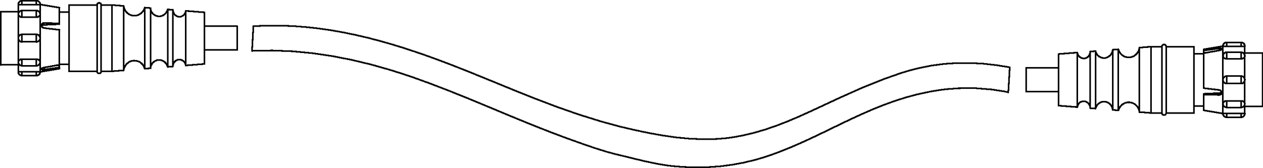
Assemble Phoenix-to-EN3 cables
When connecting loudspeakers equipped with EN3 connectors to power supplies equipped with Phoenix connectors, you'll need a Phoenix 5-pin female-to-EN3 5-pin female cable like the one shown below. The following procedure describes how to assemble this cable. If starting with an EN3-to-pigtail cable, skip steps 4–7 in this procedure.
Strip the cable jacket one (1) inch and then strip the black, red, blue, and white wires by 0.275 inch.
Warning
Do not tighten screws while the connector rests in a mating plug. Doing so will damage the contacts. During assembly, only hold the Phoenix connector externally in place.
With the connector oriented as shown below (lug screws up), insert the five exposed conductors into the five cable holes of a Phoenix 5-pin female cable mount connector. Use the following wiring scheme.
Secure the conductors by tightening the five screws in the Phoenix cable mount connector torqued to 0.5–0.6Nm (4.4–5.3In-Lbs).
On the other end of the cable, strip the outer cable jacket one (1) inch and then strip the black, red, blue, and white wires 0.275 inch.
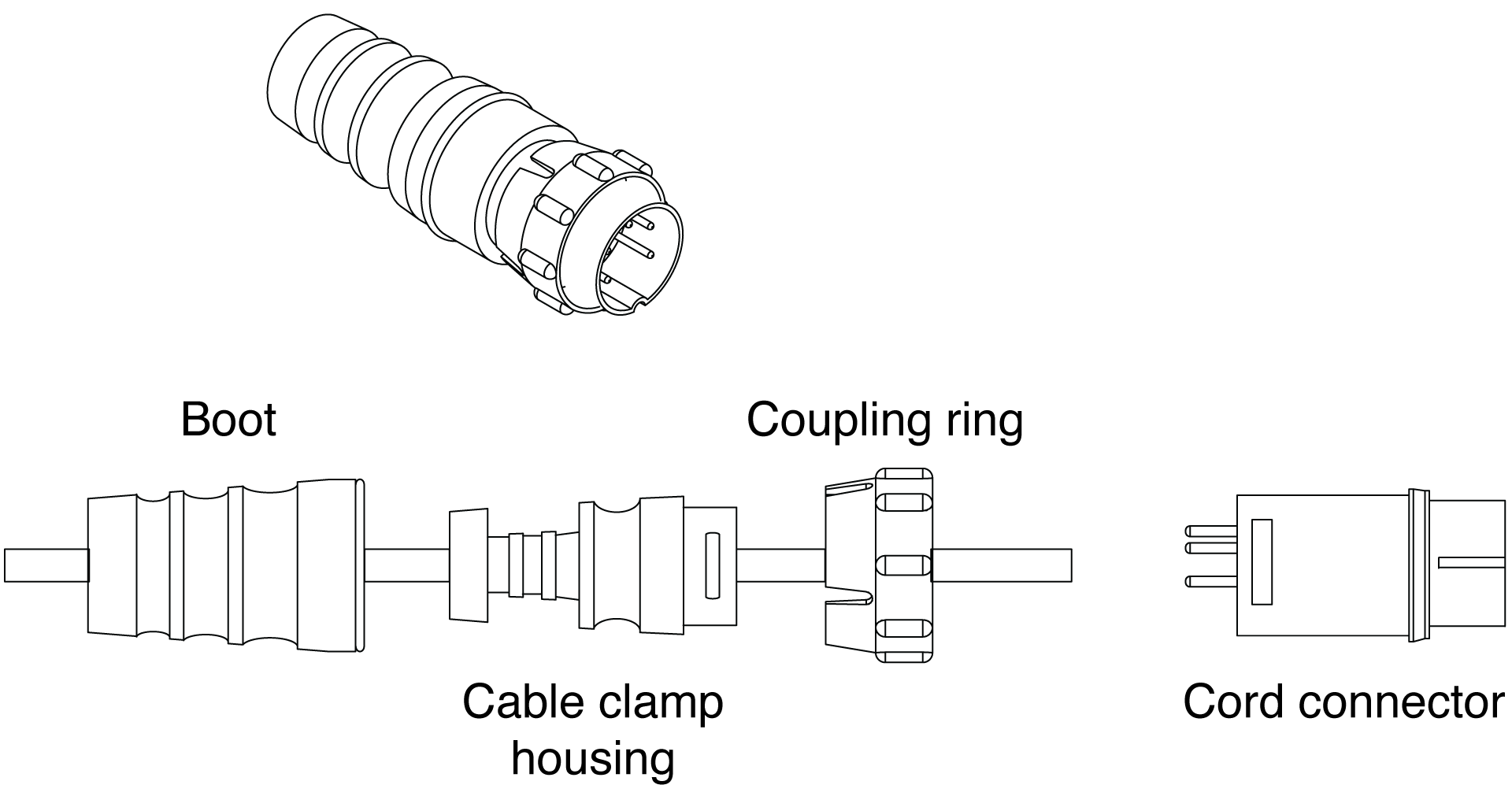
Disassemble the EN3 5-pin female connector and feed the stripped cable through the boot, cable clamp housing, and coupling ring.
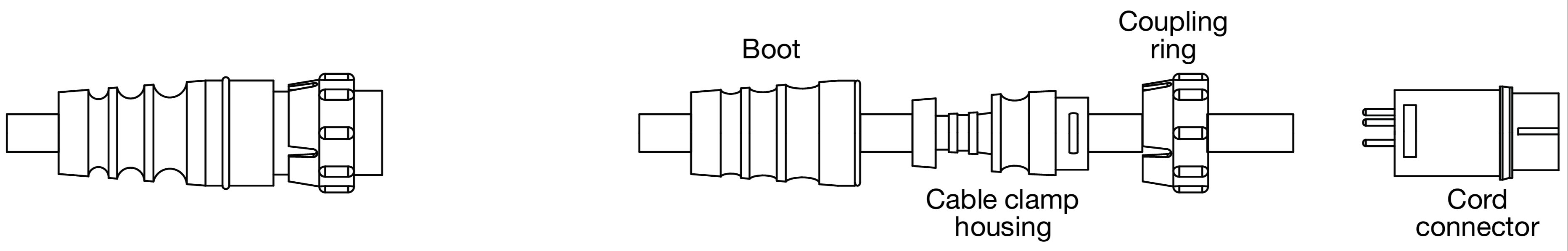
Solder the five exposed conductors to the five pins on the EN3 cord connector using the following wiring scheme.
Reassemble the EN3 5-pin female connector:
Align the coupling ring’s side notches with the cord connector’s side notches and slide the coupling ring onto the cord connector.
Carefully insert the end of the cable clamp housing into the cord connector until it locks into place. Snap the cable clamps into their compartments in the cable clamp housing.
Slide the boot forward until it completely covers the cable clamp housing.
Using a continuity or impedance meter, verify that each pin on one connector connects to the corresponding pin on the other connector.
Assemble EN3-to-EN3 cables for legacy MPS power supplies
To connect an IntelligentDC loudspeaker to a legacy MPS power supply, you may need an EN3 5-pin female to EN3 5-pin male cable like the one shown below. The following procedure describes how to assemble this cable. If you start with an EN3-to-pigtail cable, you can disregard step 5 in the procedure.
Note
Cable mount connectors cannot connect to other cable mount connectors. Cable mount connectors can only connect to panel mount connectors (like those on the loudspeaker and legacy MPS power supplies) or inline connectors. To extend cables with EN3 connectors on both ends you can use an EN3 5-pin female-to-male cable coupler (PN 28.163.033.01).
Strip one end of the cable's outer shielding by one (1) inch and then strip the black, red, blue, and white wires by 0.275 inch.
Disassemble the EN3 5-pin male connector and feed the stripped cable through the boot, cable clamp housing, and coupling ring.
Solder the five exposed conductors to the five pins on the EN3 cord connector using the following wiring scheme.
Reassemble the EN3 5-pin male connector:
Align the coupling ring’s side notches with the cord connector’s side notches and slide the couple ring onto the cord connector.
Carefully insert the end of the cable clamp housing into the cord connector until it locks into place. Snap the cable clamps in the cable clamp housing into their compartments.
Slide the boot forward so it covers the cable clamp housing completely.
Repeat steps 1-4 to attach the EN3 5-pin female connector to the other end of the cable.

Pin Destinations for EN3 5-Pin Female Cable Mount Connector
Verify correct wiring polarity for both cable ends.
Assembling Phoenix-to-ECO-M Loudspeaker Cables
When connecting loudspeakers equipped with ECO-M connectors to the MPS-488HPp power supply, you need a Phoenix 5-pin female to ECO-M 7-pin female cable. The following procedure documents how to assemble this cable.
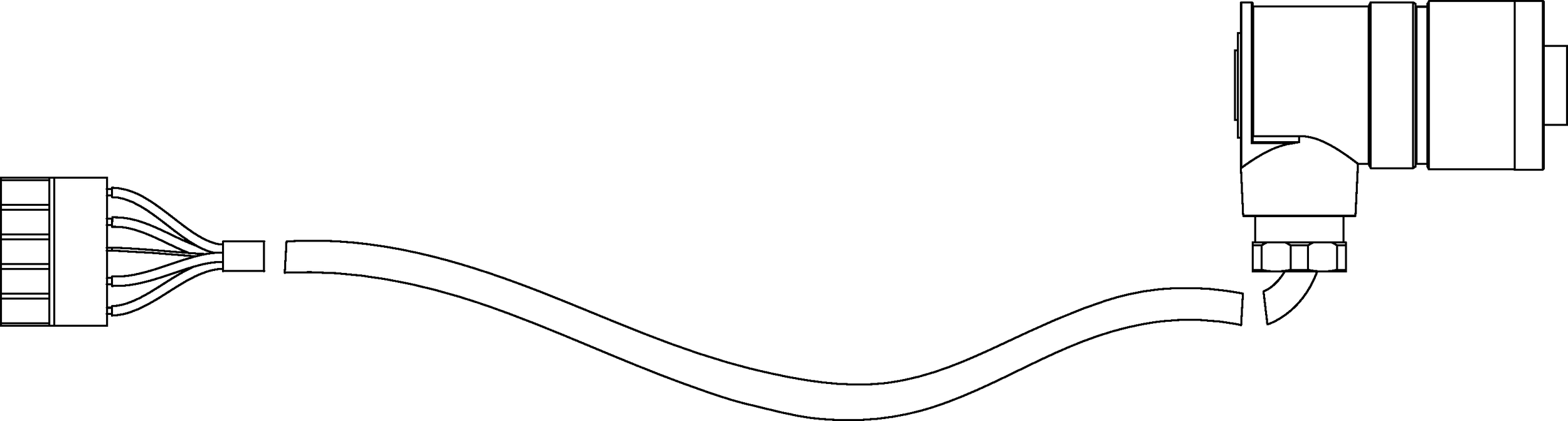
Assembled Phoenix-to-ECO-M Cable
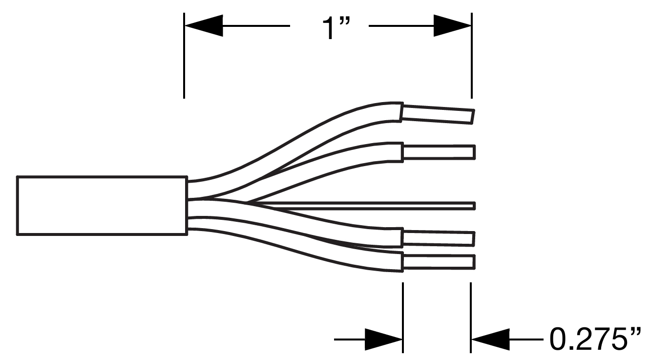
If the cable has not yet been stripped, strip one end of the cable. Strip the outer shielding by 1 inch and then strip the black, red, blue, and white wires by 0.275 inch.
Insert the five exposed conductors into the five cable holes in a Phoenix 5-pin female cable mount connector. Use the following wiring scheme.
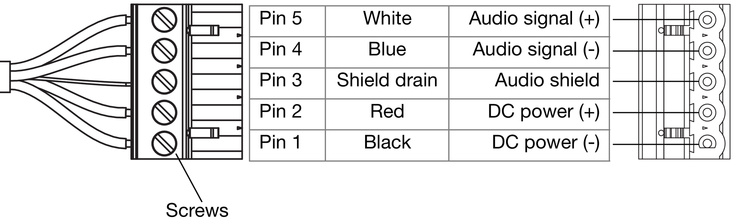
Pin Destinations for Phoenix 5-Pin Female Cable Mount Connector
Secure the conductors by tightening the five screws in the Phoenix cable mount connector. Screws should be torqued to 5–6 Nm(4.4–5.3 In-Lbs).
Caution
Screws should not be inserted into the Phoenix connector while the connector rests in a mating plug. Doing so will damage the contacts. During assembly, the Phoenix connector should only be held in place externally.
If the other (ECO-M) end of the cable has not been stripped, strip the outer shielding 1 inch and then strip the black, red, blue, and white wires 0.100 inch.
Disassemble the ECO-M 7-pin female connector and feed the stripped cable through the pressing screw, pinch ring, seal, angled hood, and sleeve.
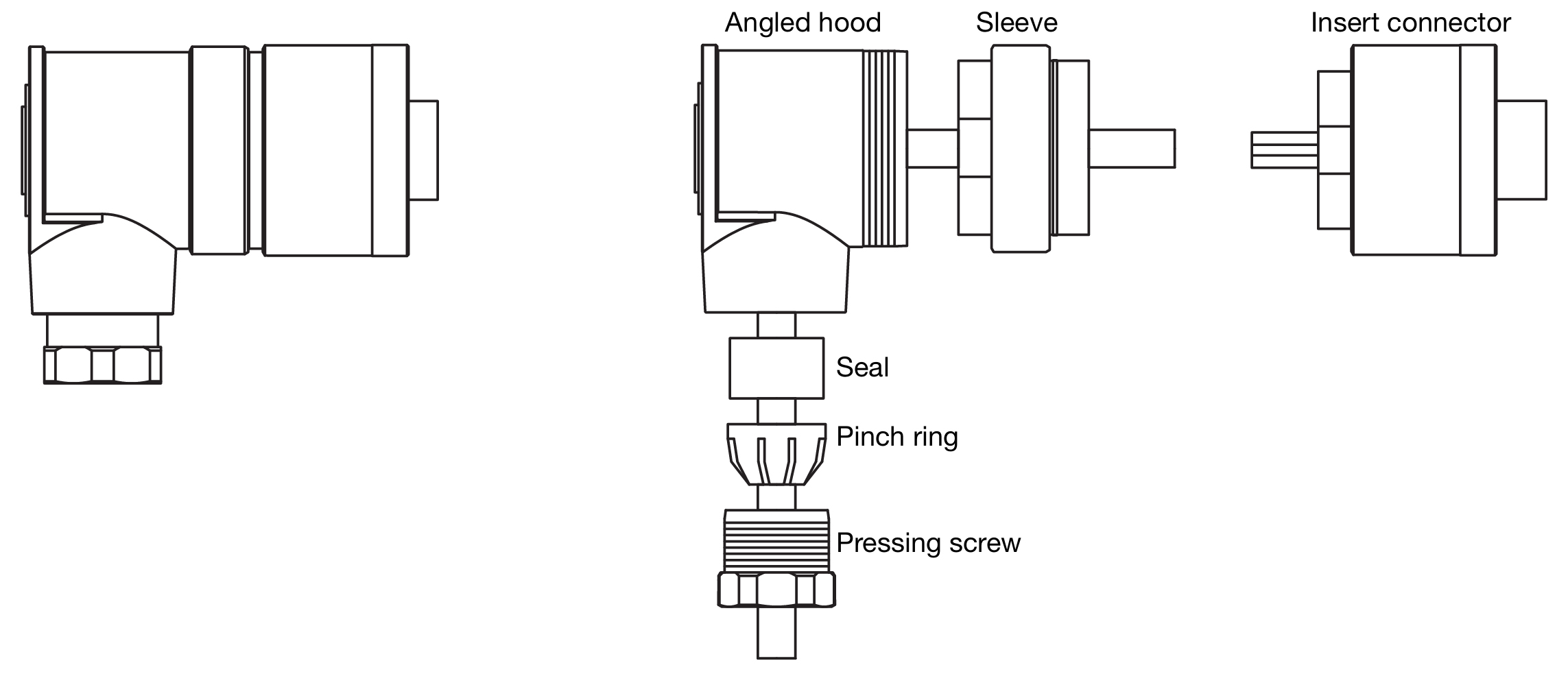
ECO-M 7-Pin Female Cable Mount Connector, Assembled (Left) and Disassembled (Right)
Fasten the five exposed conductors to the (1, 2, S, 5, and 6) pins on the ECO-M insert connector using the following wiring scheme.
Pin Destinations for ECO-M 7-Pin Female Cable Mount Connector
Reassemble the ECO-M 7-pin female connector:
Return the sleeve to the angled hood and secure it with the insert connector.
Return the seal and pinch ring to the angled hood and secure it with the pressing screw.
Verify the wiring polarity is correct for both cable ends.
Rotating the UPJ-1XP and UPJunior-XP VariO horn
The UPJ-1XP and UPJunior-XP have VariO horns that can be easily rotated to deliver either wide or narrow coverage, whether the loudspeakers are oriented vertically or horizontally. The VariO horn is factory installed with a wide coverage of 80-degree horizontal by 50-degree vertical (when the loudspeaker is oriented vertically). The horn can be rotated to provide a narrow, targeted coverage of 50-degree horizontal by 80-degree vertical (when the loudspeaker is oriented vertically).
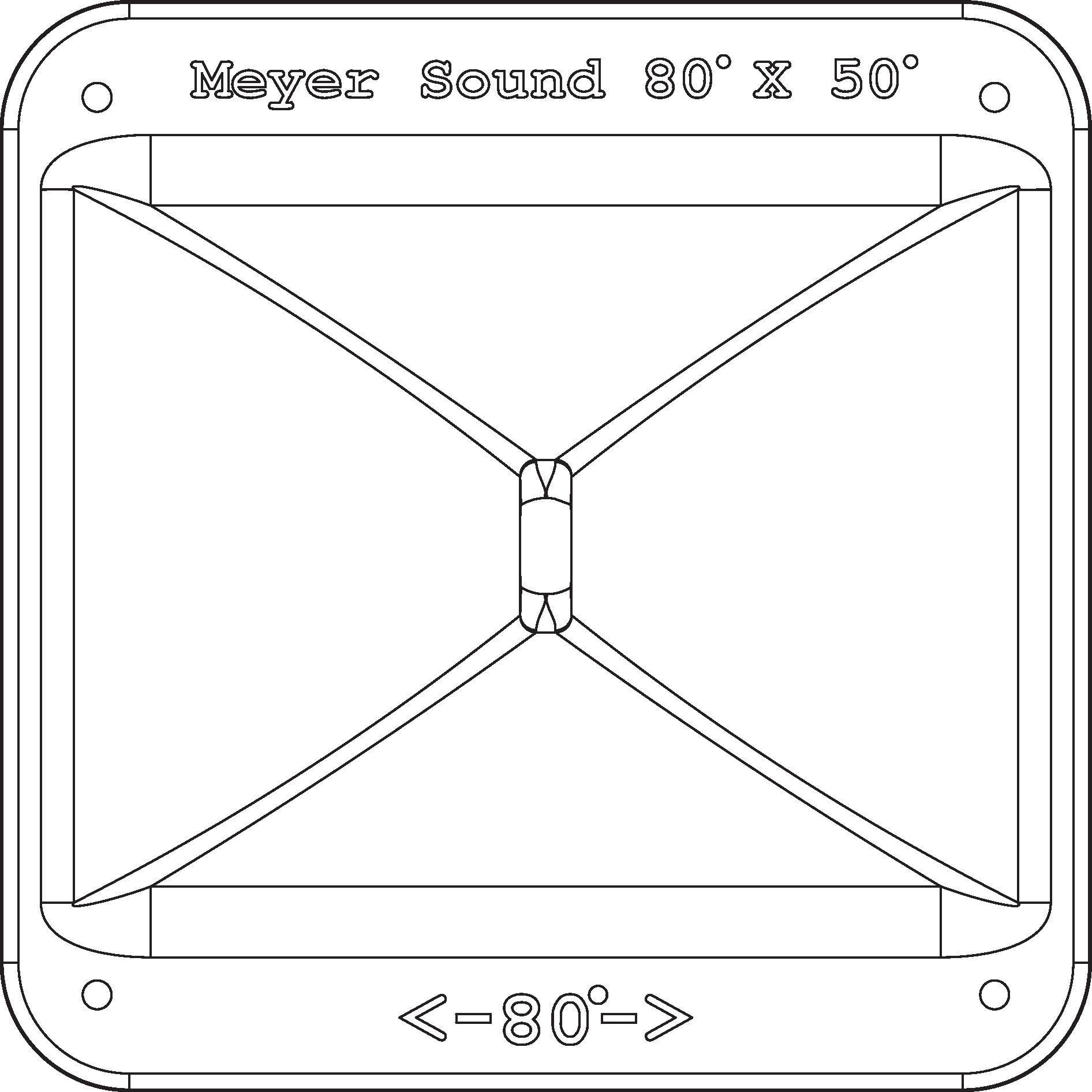
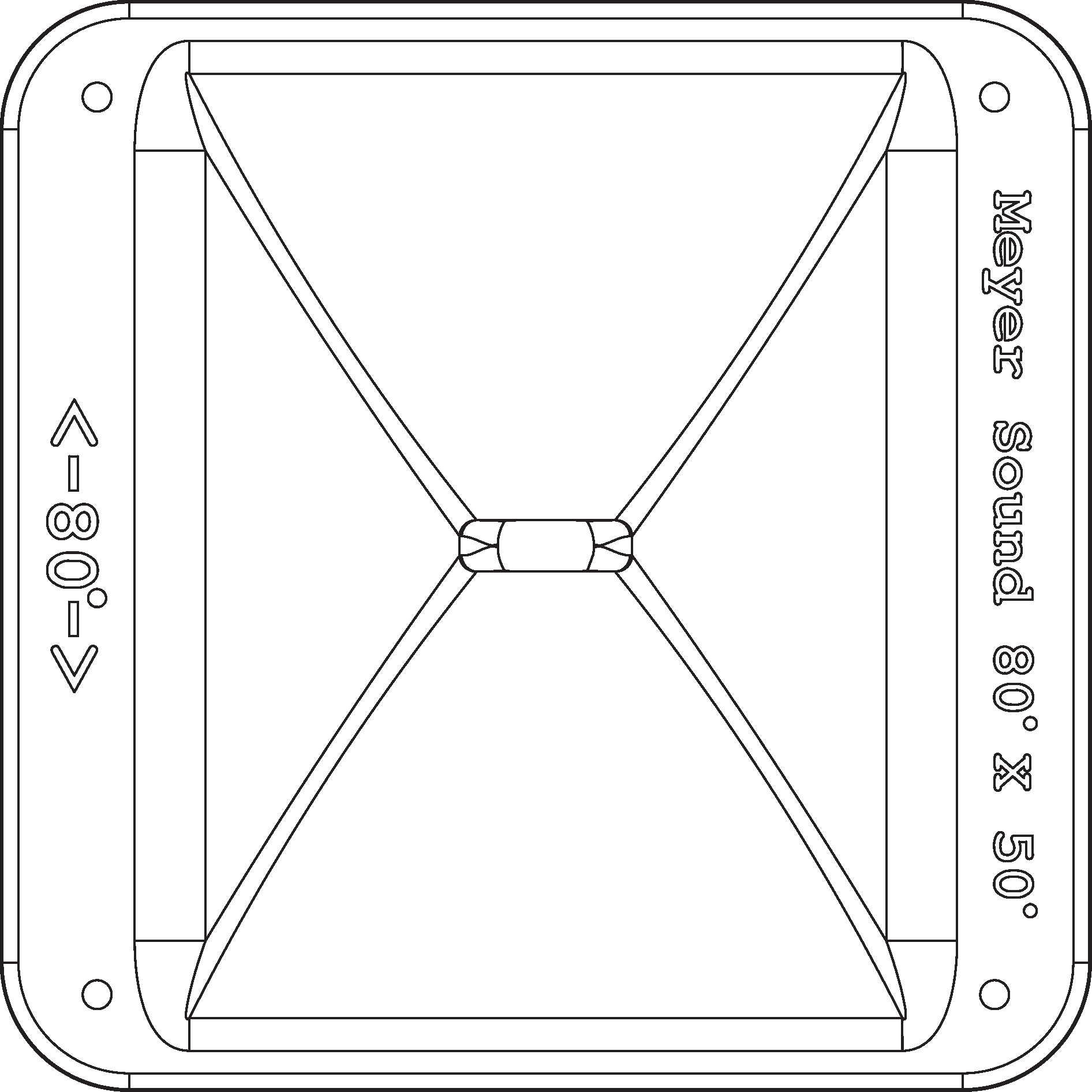
VariO Horn at 80-Degree Horizontal by 50-Degree Vertical (Left) and 50-Degree Horizontal by 80-Degree Vertical (Right)
Remove the four 10-32 x 5/8” screws from the grille cover (two from the top and two from the bottom).
Carefully remove the grille cover.
Remove the four 10-32 x 1” flange screws from the horn.
Carefully remove the horn from the cabinet, making sure not to place any stress on its wiring.
Rotate the horn 90 degrees clockwise, so its orientation is 80-degree horizontal by 50-degree vertical, with the horn’s wide flange situated near the sides of the cabinet instead of the top and bottom.
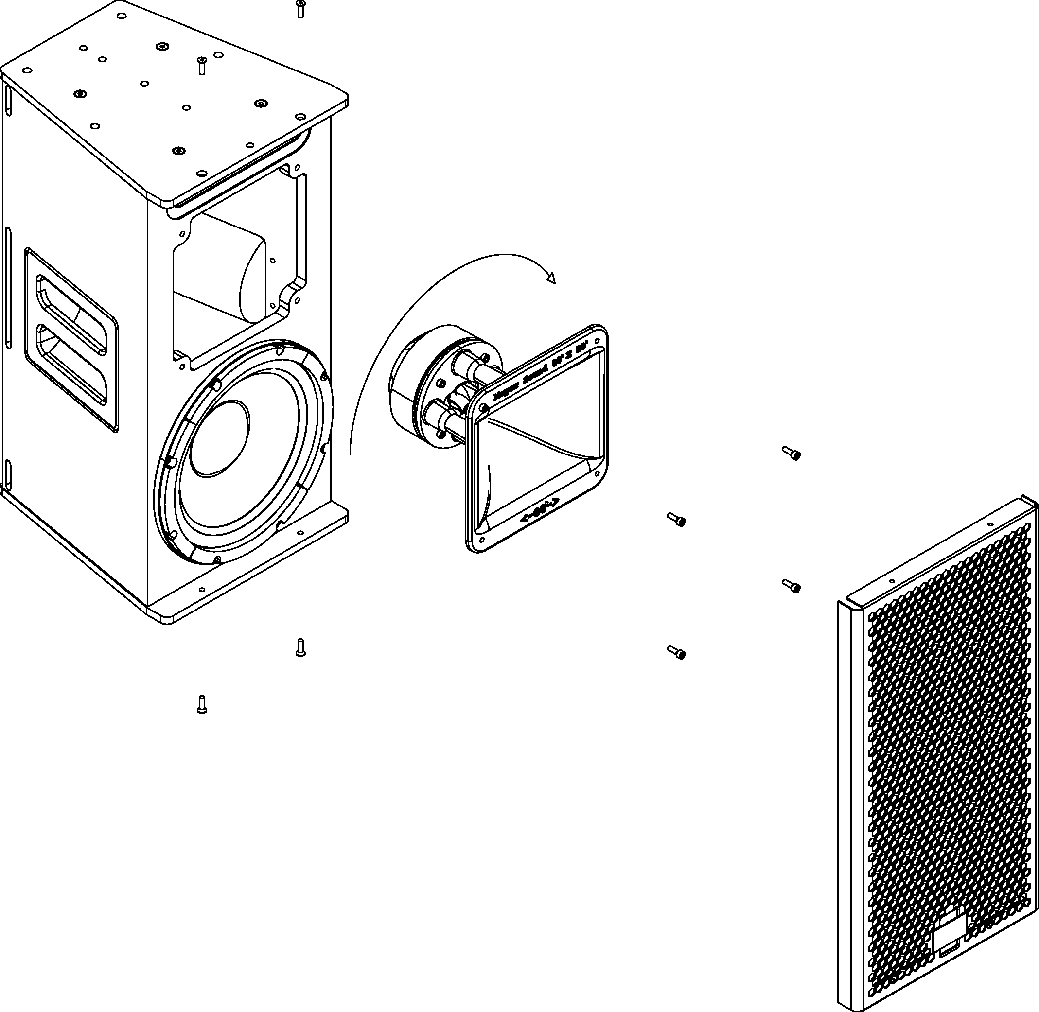
Place the horn back in the cabinet (it should fit comfortably snug) and secure it with the four 10-32 x 1” flange screws.
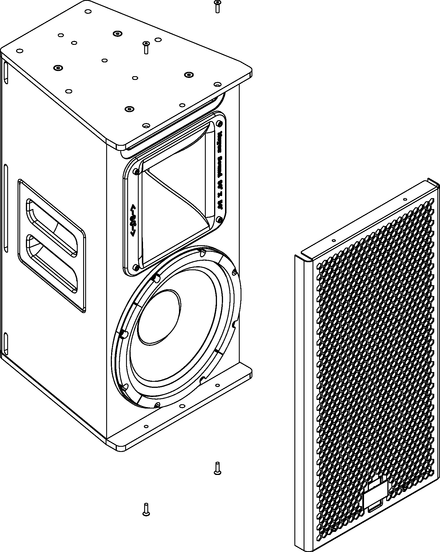
Reattach the grille cover and secure it with the four 1032 x 5/8” screws.
Tip
To rotate the Meyer Sound logo on the grille frame, pull the logo away from the grille frame, rotate it, and release.
Optional rain hoods and weather protection
Optional rain hoods, both vertical and horizontal, are available for Ultra XP loudspeakers that protect user panels from water intrusion.
Note
When using rain hoods with arrayed UPJ-1XPs or UPJunior-XPs, the maximum splay angles between loudspeakers is 40 degrees.
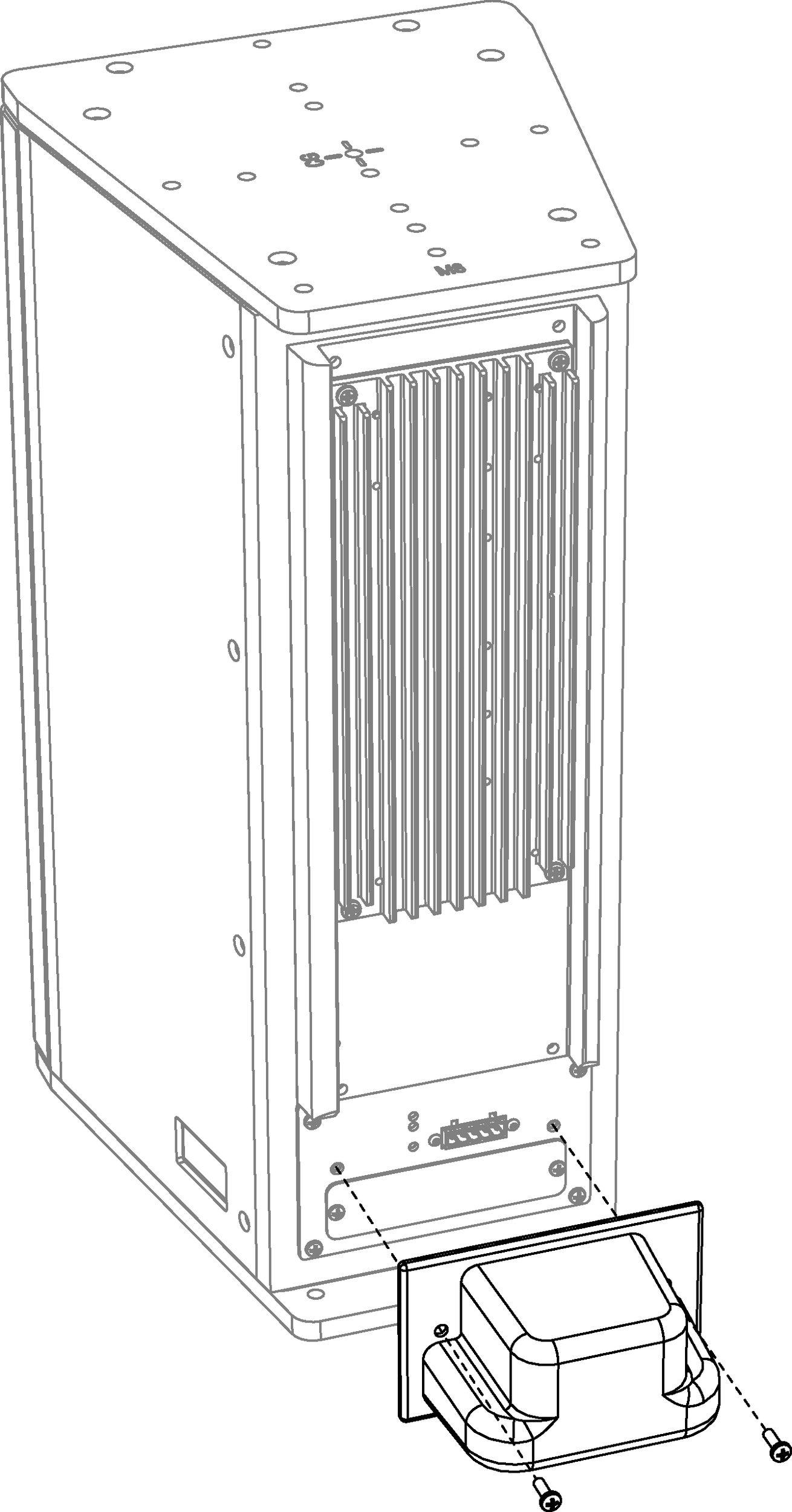
Vertical rain hood
The Ultra XP vertical rain hood should be used when loud- speakers are oriented vertically.
Vertical rain hood kit contents
Item | Part Number | Quantity |
|---|---|---|
Vertical rain hood | 66.196.062.01 | 1 |
Pan head screws | 101.008 | 2 |
Installing the vertical rain hood
Orient the Ultra XP loudspeaker vertically and attach any required cables.
Align the vertical rain hood with the user panel and its two center holes.
Secure the vertical rain hood to the user panel with the included pan head screws.
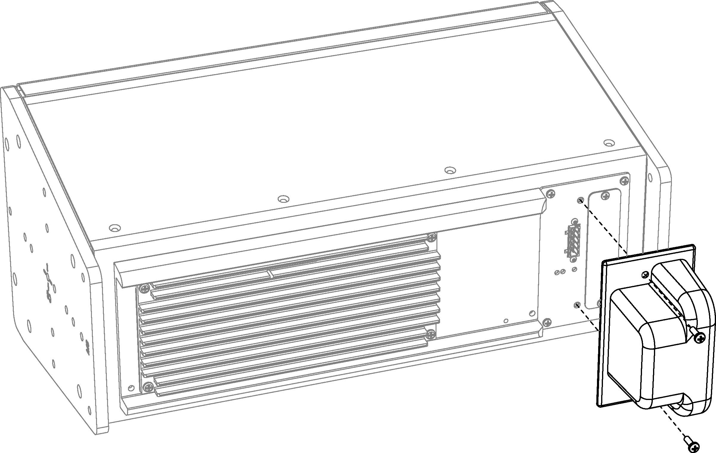
Horizontal rain hood
The Ultra XP horizontal rain hood should be used when loudspeakers are oriented horizontally.
Horizontal Rain Hood Kit Contents
Item | Part Number | Quantity |
|---|---|---|
Horizontal rain hood | 66.196.062.02 | 1 |
Pan head screws | 101.008 | 2 |
Installing the horizontal rain hood
Orient the Ultra XP loudspeaker horizontally and attach any required cables.
Align the horizontal rain hood with the user panel and its two center holes.
Secure the horizontal rain hood to the user panel with the included pan head screws.
Weather-protected UPM-1XP and UPM-2XP loudspeakers
Weather-protected versions of the UPM-1XP and UPM-2XP are available for fixed, outdoor installations. The weather-protected cabinets differ from normal models in that the orientation of the loudspeaker is flipped and the rear panel connectors are located at the top instead of the bottom.
Caution
The weather-protected UPM-1XP and UPM-2XP loudspeakers can be mounted vertically or horizontally but must be mounted with a 0-degree tilt, or preferably with downtilt, to ensure the loudspeaker’s electronics are shielded from the elements.
Reversed rain hood kit
A special reverse rain-hood kit is required for weather-protected UPM-1XP and UPM-2XP loudspeakers. The reversed rain hood accommodates and protects the rear panel connectors at the top of the cabinets.
Item | Part Number | Quantity |
|---|---|---|
Reversed rain hood | 66.196.062.03 | 1 |
Pan head screws | 101.008 | 2 |
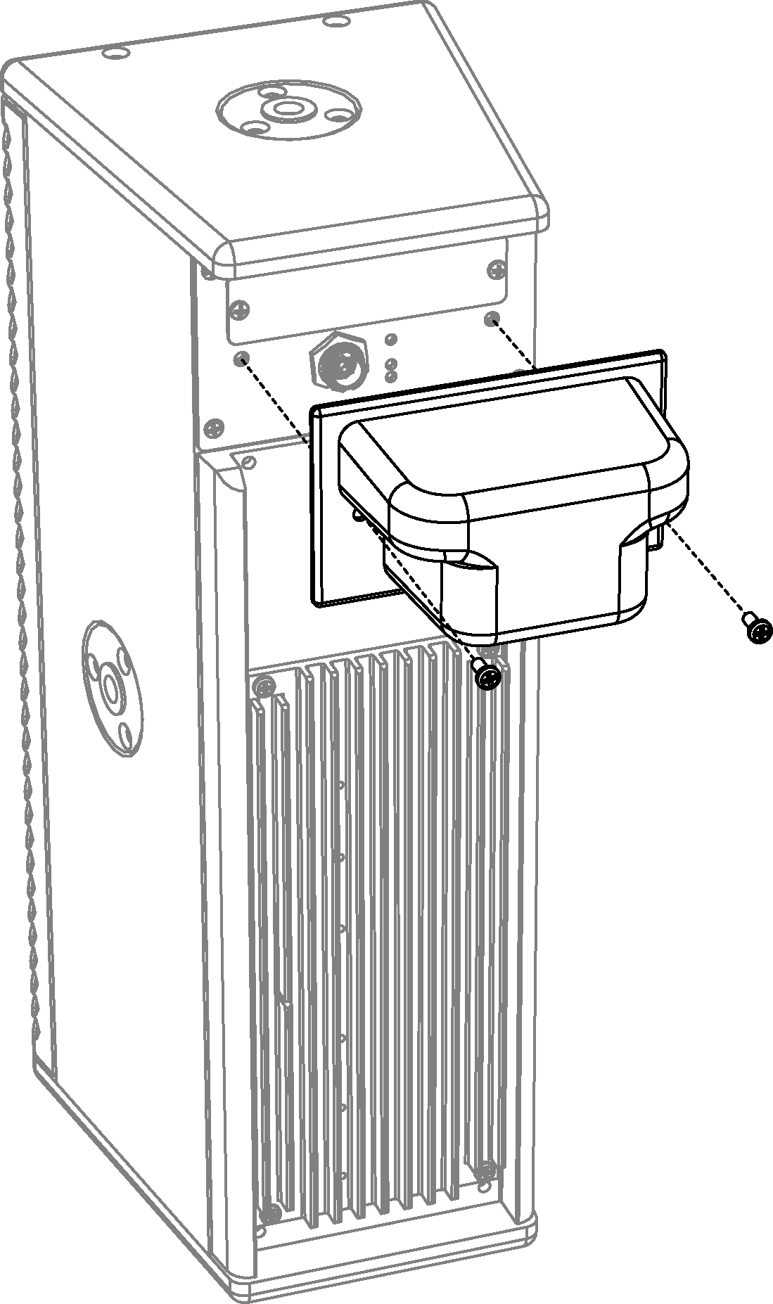
Weather-Protected UPM-1XP with Reversed Rain Hood
Ultra XP loudspeaker specifications
UPJ-1XP | UPJunior-XP | UPM-1XP | UPM-2XP | UMS-1XP | |
|---|---|---|---|---|---|
ACOUSTICAL | |||||
Operating Frequency Range | 55 Hz – 20 kHz | 70 Hz – 20 kHz | 75 Hz – 20 kHz | 80 Hz – 20 kHz | 25 Hz – 160 Hz |
Note: Recommended maximum operating frequency range. Response depends on loading conditions and room acoustics. | |||||
Frequency Response | 66 Hz – 18 kHz ±4 dB | 76 Hz – 18 kHz ±4 dB | 80 Hz – 16 kHz ±4 dB | 85 Hz – 19 kHz ±4 dB | 29 Hz – 135 Hz ±4 dB |
Note: Free-field, measured with 1/3rd octave resolution at 4 meters. | |||||
Phase Response | 750 Hz – 18 kHz ±45 degrees | 250 Hz – 18 kHz ±45 degrees | 300 Hz – 18 kHz ±60 degrees | 300 Hz – 18 kHz ±60 degrees | 41 Hz – 155 Hz ±30 degrees |
Maximum Peak SPL | 128 dB | 126 dB | 123 dB | 123 dB | 127 dB |
Note: Free-field, measured with music, referred to 1 meter. | Note: Half-space loading, measured with music, referred to 1 meter. | ||||
Dynamic Range | >110 dB | ||||
Coverage | 80 x 50 degrees or 50 x 80 degrees (rotatable VariO horn) | 100 x 100 degrees | 45 x 45 degrees | 360 degrees for single unit; for multiple units, varies with configuration | |
Acoustical Crossover | 2000 Hz | 3500 Hz | 1300 Hz | 2300 Hz | - |
Note: At this frequency, the transducers produce equal sound pressure levels. | |||||
TRANSDUCERS | |||||
Low Frequency | One 10-inch cone driver | One 8-inch cone driver | Two 5-inch cone drivers | Two 5-inch cone drivers | Two 10-inch cone drivers |
Note: UPM-1XP/UPM-2XP low-frequency drivers are active below 320 Hz. From 320 Hz to the 1300 Hz crossover point, only one low-frequency driver, the one closest to the high-frequency driver, is active, to maintain optimal polar and offaxis frequency response characteristics. | |||||
High Frequency | One 3-inch diaphragm compression driver | One 2-inch diaphragm compression driver | One 1-inch metal dome tweeter | One 1-inch metal dome tweeter | - |
CONNECTOR OPTIONS | |||||
Note: Audio shield, chassis/earth through 50 ohms, 1000 pF, 15 V clamped network to provide virtual ground lift at audio frequencies | |||||
AUDIO INPUT | |||||
Type | Differential, electronically balanced | ||||
Maximum Common Mode Range | ±15 V DC, clamped to earth for voltage transient protection | ||||
Input Impedance | 10 kOhm differential between positive (+) and negative (–) audio pins | ||||
DC Blocking | Differential DC blocking up to the maximum common mode voltage | ||||
CMRR | >50 dB, typically 80 dB (50 Hz – 500 Hz) | ||||
RF Filter | Common mode: 425 kHz; Differential mode: 142 kHz | ||||
TIM Filter | <80 kHz, integral to signal processing | ||||
Nominal Input Sensitivity | 0.0 dBV (1.0 V rms) continuous is typically the onset of limiting for noise and music | 0.0 dBV (1.0 V rms) continuous is typically the onset of limiting for noise and music | –8.0 dBV (0.4 V rms) continuous is typically the onset of limiting for noise and music | –8.0 dBV (0.4 V rms) continuous is typically the onset of limiting for noise and music | –4.0 dBV (0.6 V rms) continuous is typically the onset of limiting for noise and music |
Input Level | Audio source must be capable of producing +20 dBV (10 V rms, 14 V peak) into 600 ohms to produce the maximum peak SPL over the operating bandwidth of the loudspeaker | ||||
AMPLIFIER | |||||
Amplifier Type | 2-channel, class D | 2-channel, class D | 3-channel, class D | 3-channel, class D | 2-channel, class D |
Output Power | 300 W total | 300 W total | 350 W total | 350 W total | 450 W total |
Note: Wattage rating based on the maximum unclipped burst sine-wave rms voltage the amplifier will produce into the nominal load impedance. | |||||
THD, IM TIM | <.02% | ||||
Load Capacity | 4 ohms low channel, 16 ohms high channel | 4 ohms low channel, 12 ohms high channel | 8 ohms low channel, 8 ohms high channel | 4 ohms both channels | |
Cooling | Convection | ||||
DC POWER | |||||
Voltage Requirement | 48 V DC | ||||
Note: Meyer Sound power supply required. For information and specifications on the MPS-488HP IntelligentDC external power supply, refer to its datasheet. | |||||
PHYSICAL | |||||
Enclosure | Premium birch plywood | ||||
Finish | Black textured | ||||
Protective Grille | Powder-coated, hexstamped steel with black mesh screen | ||||
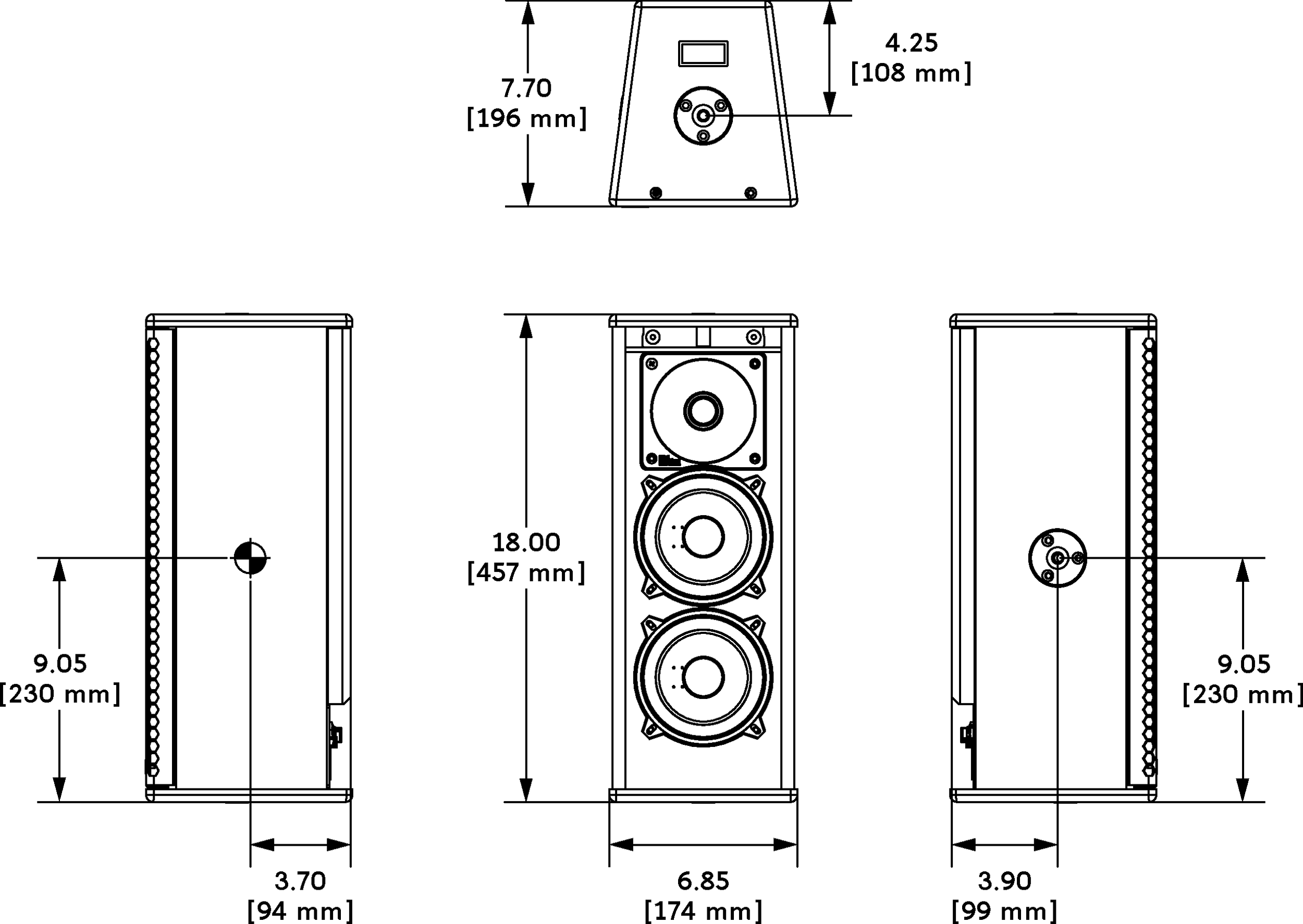
Dimensions | 11.15” w (283 mm) 22.43” h (570 mm) 12.25” d (311 mm) | 9.00” w (229 mm) 19.04” h (484 mm) 10.20” d (259 mm) | 6.85” w (174 mm) 18.00” h (457 mm) 7.70” d (196 mm) | 6.85” w (174 mm) 18.00” h (457 mm) 7.70” d (196 mm) | 22.75” w (578 mm) 16.30” h (414 mm) 17.51” d (445 mm) |
Weight | 43 lbs (19.5 kg) | 26 lbs (11.8 kg) | 17 lbs (7.7 kg) | 58 lbs (26.3 kg) | |
ENVIRONMENTAL | |||||
Operating Temperature | 0° C to +45° C | ||||
Non Operating Temperature | –40° C to +75° C | ||||
UPJ-1XP dimensions
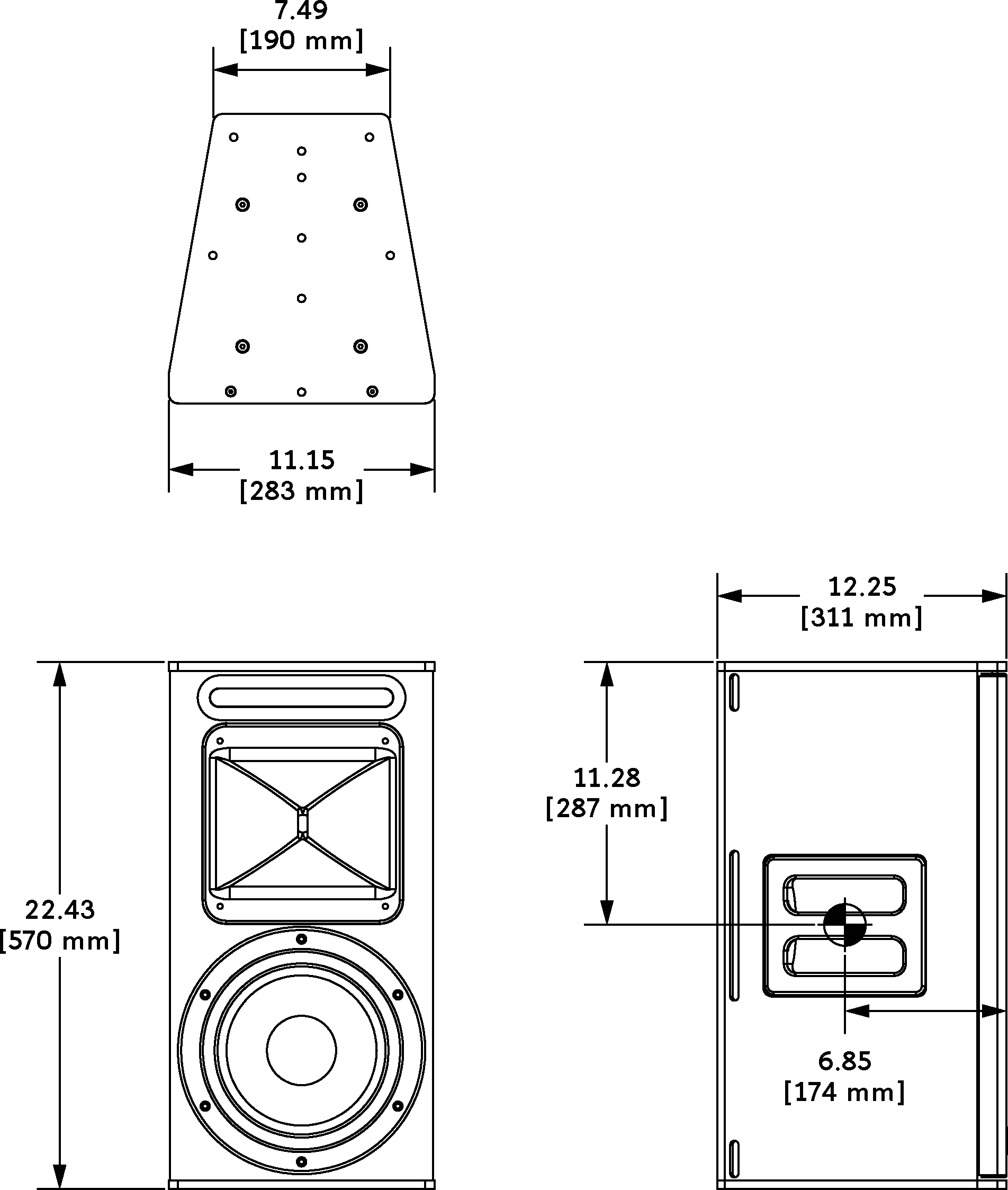
UPJ-1XP DIMENSIONS
UPJunior-XP dimensions
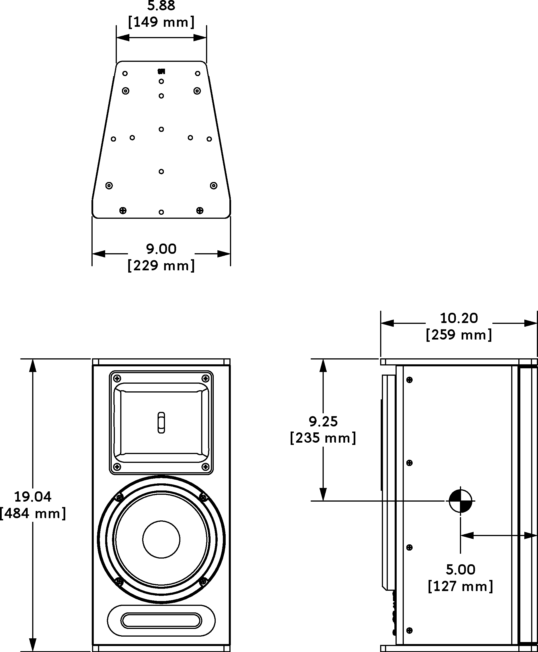
UPJunior-XP Dimensions
UPM-1XP dimensions

UPM-1XP Dimensions
UPM-2XP dimensions
UMS-1XP dimensions
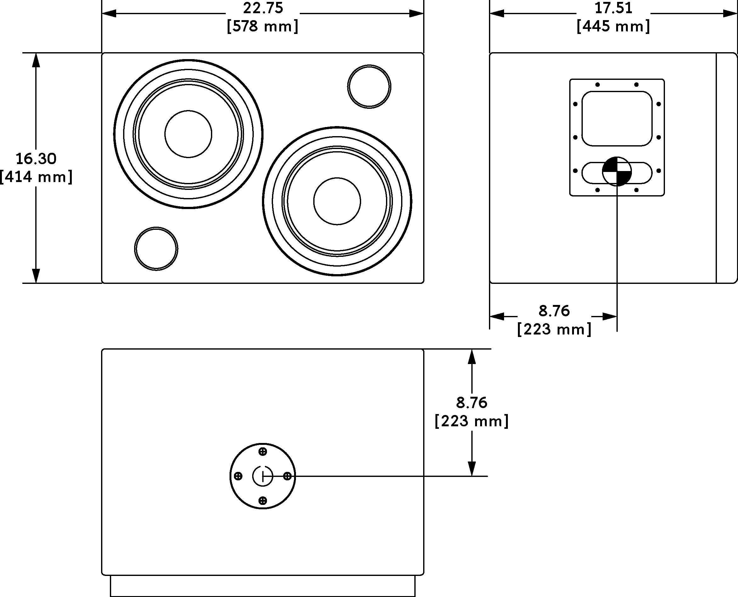
UMS-1XP Dimensions