Datasheet — ULTRA-X40 | 42
Wide (X40) and Controlled (X42) Coverage Loudspeakers

 |
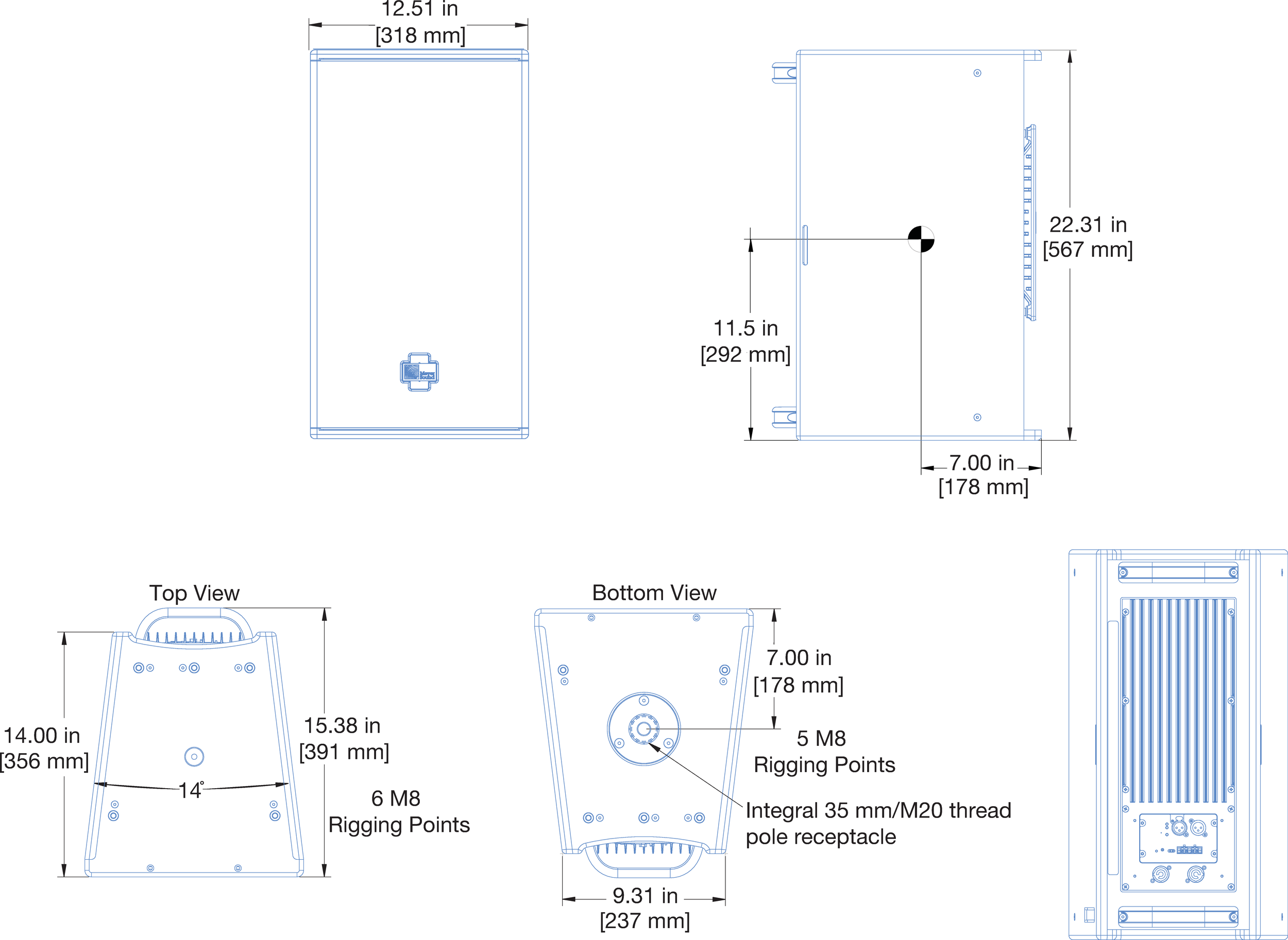 |
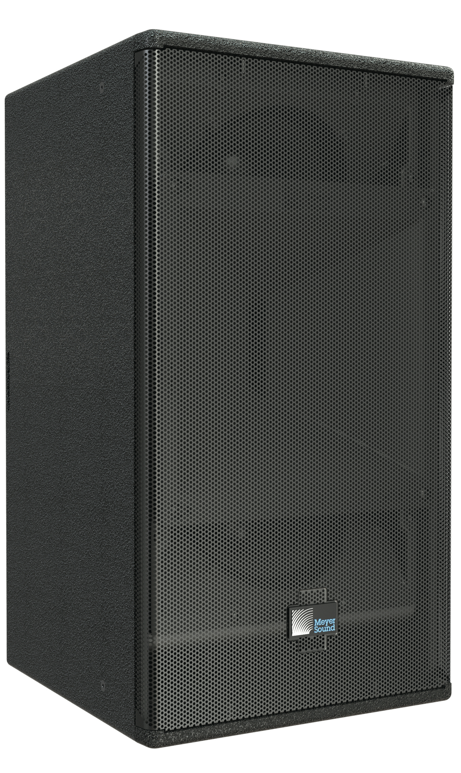
ULTRA-X40 Loudspeaker and Dimensions
Meyer Sound’s ULTRA-X40 and ULTRA-X42 designs continue the tradition of the highly successful UPA loudspeakers—so versatile they have been a universal standard in almost every application for over 35 years. From touring performances to theme parks, worship venues to theater shows, and lecture halls to large scale concerts, Meyer Sound technology has delivered exceptional fidelity with high power, low distortion, and uniformly predictable behavior.
To this legacy, Meyer Sound incorporated technology from the popular and award-winning LEO® family of loudspeakers to bring multiple enhancements to bear in the ULTRA-X40/42 designs:
Innovative, highly efficient class-D amplifier and advanced signal processing that reproduce any sound source with linearity over a wide dynamic range.
Weight reduction of 25 lb (11 kg), as well as a reduction in overall size compared to the UPA loudspeakers for increased power-to-weight and -size ratios.
Concentric driver configuration with all the benefits of a coaxial driver, yet none of the disadvantages. In addition, this configuration supports directional control of frequencies down to 400 Hz.
Extremely well-behaved, rotatable horns designed for very precise, even coverage. These horn designs, in conjunction with the concentric driver configuration, deliver consistent patterns despite the orientation.
With these enhancements, the ULTRA-X40/42 loudspeakers provide high power output, low distortion, and consistent polar response in a more compact, vented enclosure. The ULTRA-X40 loudspeaker features two 8-inch cone low-frequency drivers and one 3-inch diaphragm compression driver coupled with a rotatable 110° x 50° Constant-Q horn. A more controlled pattern is available on the ULTRA-X42 model, which is fitted with a 70° x 50° constant-Q horn.
Because of the proprietary, high-frequency horns, the beamwidth remains consistent within close tolerances in both the horizontal and vertical planes and across the horns’ operating frequency range. Uniformly predictable polar behavior takes much of the guesswork out of system design and assures optimal system performance.
A proprietary three-channel, class-D digital power amplifier powers the ULTRA-X40/42 loudspeakers, which each have a total peak power output of 1950 watts. Advanced audio processing includes electronic crossover, correction filters for phase and frequency response, and driver protection circuitry. Phase-corrected electronics ensure flat acoustical amplitude and phase response, resulting in exceptional impulse response and precise imaging. The amplifier/processing package incorporates Meyer Sound’s Intelligent AC™, which auto-selects the correct operating voltage, suppresses high voltage transients, filters EMI and provides soft-start power-up. The ULTRA-X40/42 cabinet provides audio XLR and powerCON20 input and looping output connectors.
The optional RMS remote monitoring system module provides comprehensive monitoring of loudspeaker parameters from a host computer running Compass® software.
Meyer Sound builds the trapezoidal enclosure out of premium multi-ply birch with a slightly textured black finish. A powder-coated, round-perforated steel grille provides protection to the front of the loudspeaker.
The ULTRA-X40/42 includes 11 integral M8 rigging points. It also includes an integral 35 mm stand mount receptacle with M20 threads for added stability. With this versatile integrated rigging, the ULTRA-X40/42 is ready for a wide variety of applications including those requiring pole mounting, hanging individually in horizontal or vertical orientations, or clustering.
Optional rigging accessories include an adjustable 35 mm pole with M20 slug, a U-bracket, a yoke, a pinnable link on a channel that allows the hanging of multiple units from a single pick-up point, and cluster plates for horizontal and vertical loudspeaker grouping. Other options include weather protection and custom color finishes.
Features and Benefits
Exceptional fidelity and surprising power capability delivered in a compact, light enclosure
Extraordinarily flat amplitude and phase response ensures tonal accuracy and precise imaging
Wide (ULTRA-X40) or Controlled (ULTRA-X42) pattern
Rotatable horn provides installation flexibility
Integral stand mount and QuickFly® mounting options facilitate rigging
Applications
Stadiums and theme parks
Concert halls and houses of worship
Theatrical sound reinforcement
Portable and installed audio-visual systems
Nightclubs
Compact voice reinforcement systems
Accessories and Associated Products
MCP50-X40 Cluster Plate — The MCP50-X40 50 Degree Cluster Plate kit includes two cluster plates to facilitate installation of ULTRA-X40/42 loudspeakers in both horizontal and vertical clusters at angles between 10 and 50 degrees in 5 degree increments. The kit includes eight M8 bolts and eight M8 knobs. The MTC-X40 Top Channel accessory (sold separately) can be attached to the MCP50-X40 as a top pick up point.
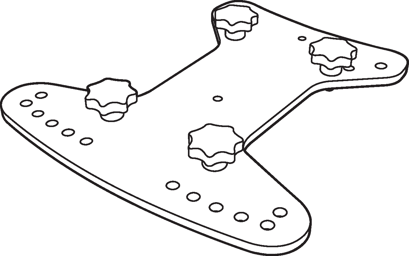 |
MCP50-X40 Cluster Plate
MCP70-X40 Cluster Plate — The MCP70-X40 70 Degree Cluster Plate kit includes two cluster plates to facilitate installation of ULTRA-X40/42 loudspeakers in both horizontal and vertical clusters at angles between 40 and 70 degrees in 5 degree increments. The kit includes eight M8 bolts and eight M8 knobs. The MTC-X40 Top Channel accessory (sold separately) can be attached to the MCP70-X40 as a top pick up point.
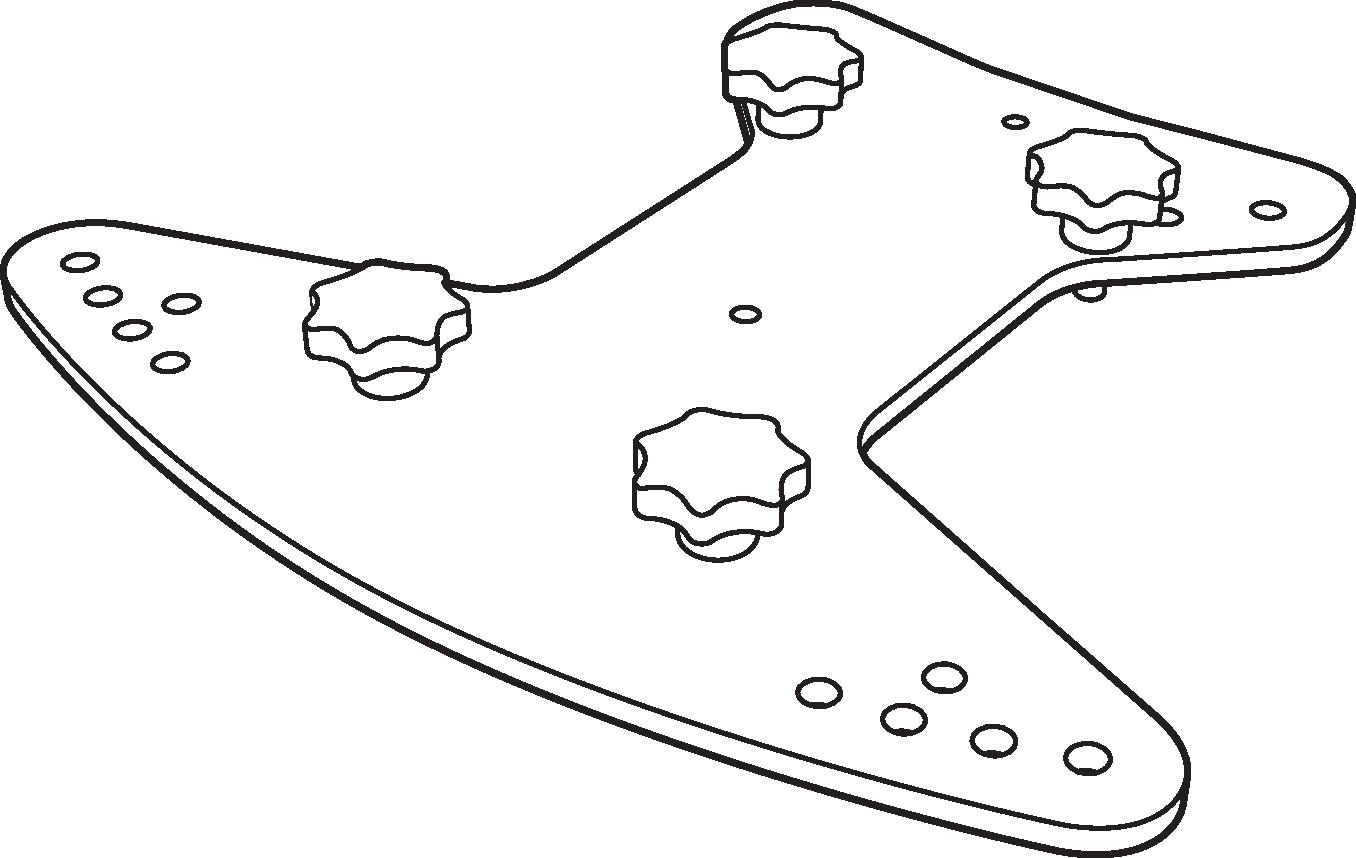 |
MCP70-X40 Cluster Plate
MPK-POLE 35MM/M20 Adjustable Pole Mount — Adjustable length 927–1524 mm (36.5–60 in) pole with assisted lift. Lower shaft fits 35 mm cups or use the removable M20 threaded lug for added stability. Upper shaft includes a PAS-M20 Adapter Sleeve to fit loudspeakers with 35 mm and M20 internal pole mounts onto a 35 mm speaker stand. (Can also buy the PAS-M20 Adapter Sleeve separately). Additional 35 mm to 38 mm (1.5 in) adapter and PAS-M8 Adapter Sleeve included.
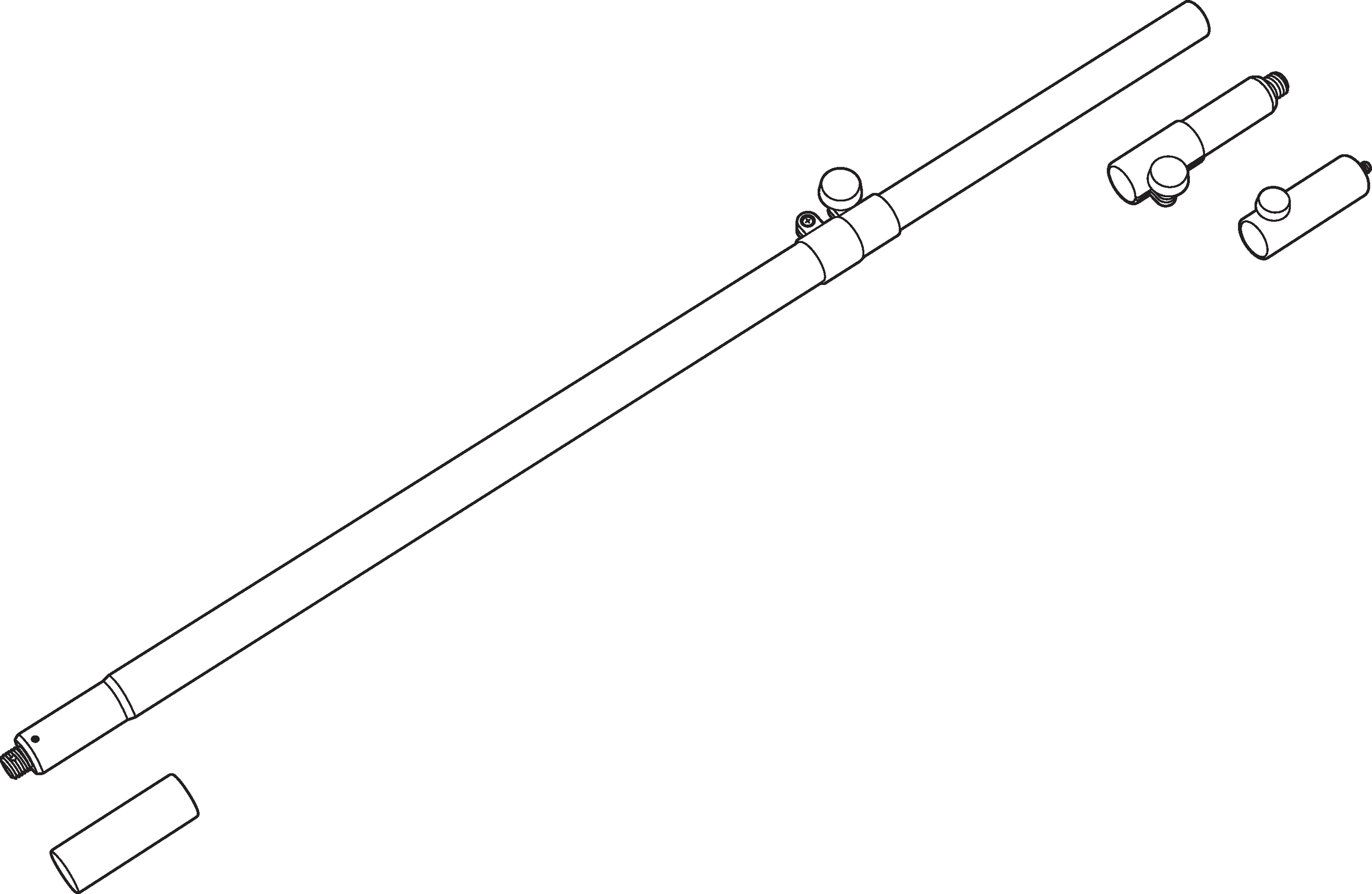 |
MPK-POLE 35MM/M20 Pole Kit (PAS-M20 and PAS-M8 Adapter Sleeves and 38 mm (1.5 in) adapter included)
MTB-X40 Top Bracket — The MTB-X40 Top Bracket kit includes a heavy-duty, U-bracket style accessory that facilitates mounting of ULTRA-X40/42 loudspeakers from the ceiling or a truss using the cluster plates. The design supports 5–25 degrees of downtilt and 5 degrees of uptilt. In addition, the MTB-X40 Top Bracket enables mounting of a single ULTRA-X40/42 onto the floor for front-fills. The kit includes four M8 bolts and four M8 knobs.
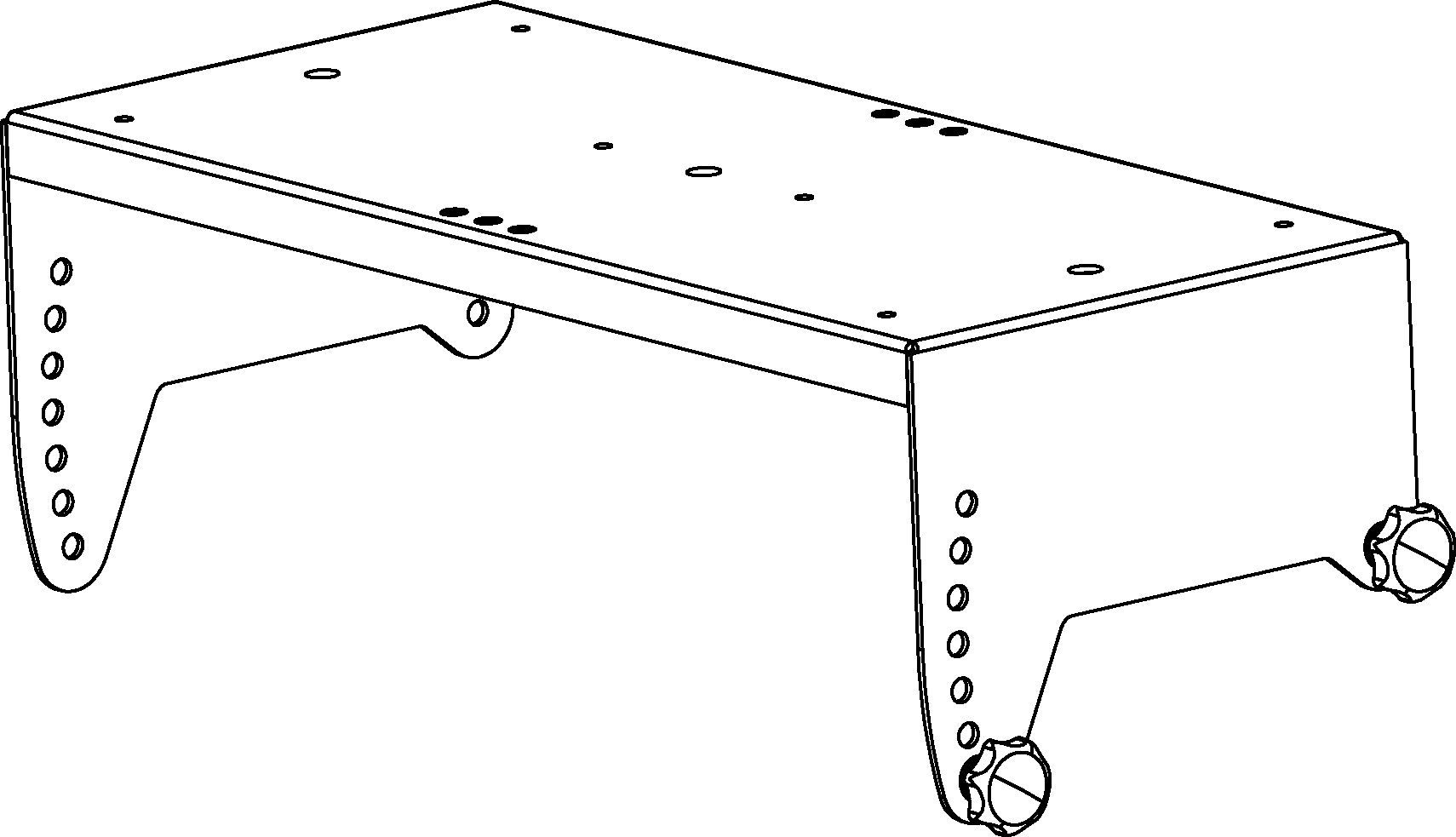 |
MTB-X40 Top Bracket
35MM Pole Stand Adapter — This large base stand adapter can be used to mount the MTB-X40 Top Bracket or the MUB-X40 U-bracket onto a pole.
MTC-X40 Top Channel — The MTC-X40 Top Channel kit includes a pinnable link in a channel that mounts directly to the top of the ULTRA-X40/42 rig nuts or into an MCP50-X40 or MCP70-X40 plate and supports pick-up of up to three ULTRA-X40/42 loudspeakers from a single point using the two included lock pins and 3/8-inch shackle. Using the MTC-X40 Top Channel at the bottom of the ULTRA-X40/42 to pick up multiple loudspeakers requires the use of a Thread Reducer M20 to M8 (35MM), which is not included.
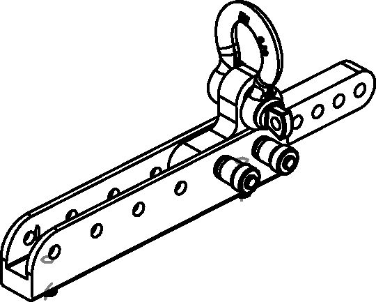 |
MTC-X40 Top Channel
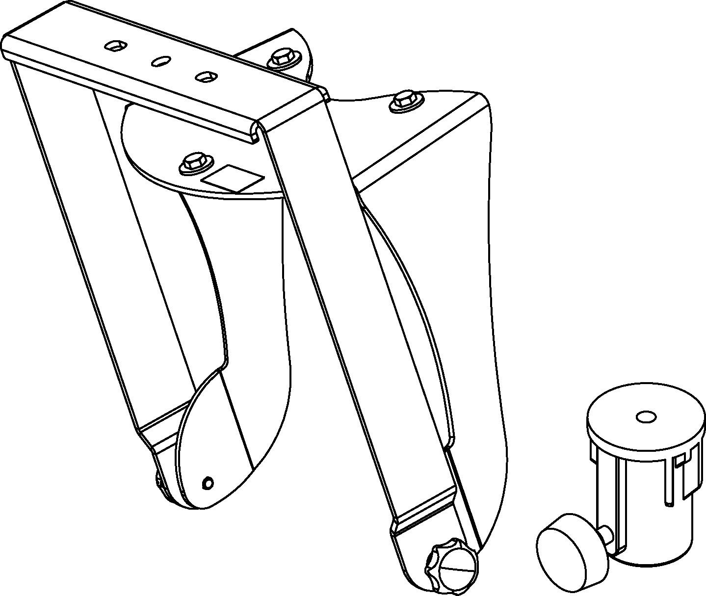
MUB-X40 U-Bracket The MUB-X40 U-Bracket allows a single ULTRA-X40/42 loudspeaker to be mounted to a wall (in either vertical or horizontal orientations), to the ceiling or onto the floor. The kit includes two M8 bolts, two M8 knobs, and a Thread Reducer M20 to M8 (35 MM) to convert the cabinet’s built-in pole mount internal threads to M8 size. The MUB-X40 U-Bracket can also mount an ULTRA-X40/42 to a pole horizontally using the optional 35MM Pole Stand Adapter.
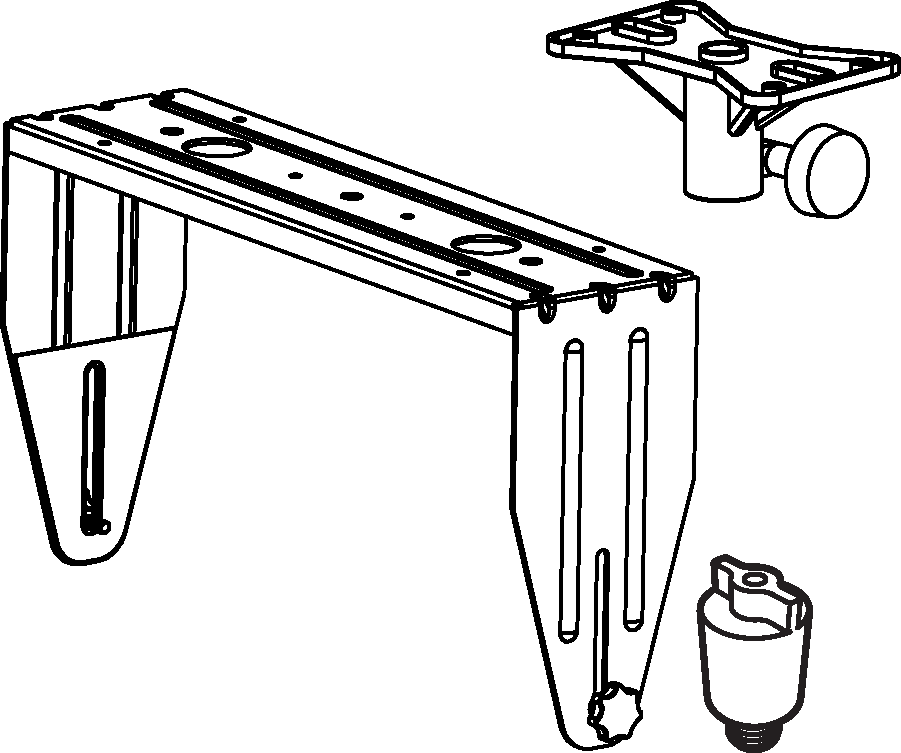 |
MUB-X40 U-Bracket and included Thread Reducer M20 to M8 (35 mm) shown with optional 35MM Pole Stand Adapter
MYA-X40 Mounting Yoke The MYA-X40 Yoke suspends a single ULTRA-X40/42 loudspeaker and supports a wide range of horizontal and vertical adjustments. The yoke attaches to the top of the loudspeaker using three rig nuts. The kit includes three M8 bolts and three M8 knobs. The yoke may also be mounted on a 35 mm pole using the optional MSA-STAND Adapter Cup 35MM accessory to facilitate easy panning and tilting.
 |
MYA-X40 Yoke and optional MSA-STAND Adapter Cup 35MM
MSA-STAND Adapter Cup 35MM — This compact cup-type adapter can be used to mount the MYA-X40 Mounting Yoke on a pole to allow for easy panning and tilting of the ULTRA-X40/42.
Thread Reducer M20 to M8 (35 mm) — The Thread Reducer kit includes a 35 mm diameter, M20 to M8 thread size adapter to convert the cabinet’s built-in pole mount internal threads to M8 size. It is necessary for installing the MUB-X40 U-Bracket (one is included in the MUB-X40 U-Bracket kit) and when installing the MTC-X40 Top Channel or eye bolts at the bottom of a cabinet (not included in the eye bolts or MTC-X40 Top Channel kits).
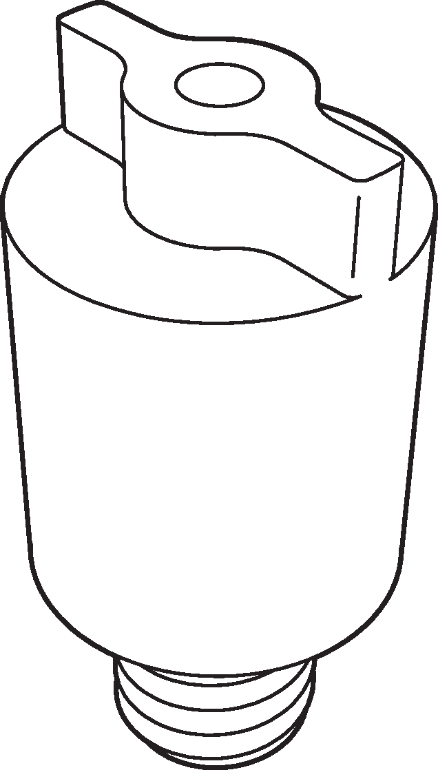 |
Thread Reducer M20 to M8 (35 mm)
Specifications
ACOUSTICAL | ULTRA-X40 | ULTRA-X42 |
Operating Frequency Range2 | 55 Hz – 19.5 kHz | 55 Hz – 19.5 kHz |
Frequency Response3 | 56 Hz – 19 kHz ± 4 dB | 58 Hz – 18 kHz ± 4 dB |
Phase Response | 90 Hz – 19.5 kHz ±45° | 90 Hz – 19.5 kHz ±45° |
Maximum SPL4 | 138 dB | 140 dB |
Linear Peak SPL5 | 132.5 dB with 18 dB crest factor (M-noise), 130 dB (Pink Noise), 131 dB (B-noise) | 134 dB with 18.5 dB crest factor (M-noise), 132 dB (Pink Noise), 134 dB (B-noise) |
COVERAGE | ||
Rotatable horn: 110° x 50° | Rotatable horn: 70° x 50° | |
TRANSDUCERS | ||
Low Frequency | Two 8-inch cone drivers; 4 Ω nominal impedance | |
High Frequency | One 3-inch diaphragm compression driver connected to a rotatable horn; 8 Ω nominal impedance | |
AUDIO INPUTS | ||
Type | Differential, electronically balanced | |
Maximum Common Mode Range | ±15 V DC, clamped to earth for voltage transient protection | |
Connectors | XLR 3-pin female input with male loop output; optional XLR 5-pin connector to accommodate both balanced audio and RMS signals. | |
Input Impedance | 10 kΩ differential between pins 2 and 3 | |
Wiring6 | Pin 1: Chassis/earth through 1 kΩ, 1000 pF, 15 V clamp network to provide virtual ground lift at audio frequencies Pin 2: Signal + Pin 3: Signal – Pin 4: RMS (polarity insensitive) Pin 5: RMS (polarity insensitive) Case: Earth ground and chassis | |
Nominal Input Sensitivity | 0 dBV (1.0 V rms) continuous is typically the onset of limiting for noise and music | |
Input Level | Audio source must be capable of producing of +20 dBV (10 V rms) into 600 Ω to produce the maximum peak SPL over the operating bandwidth of the loudspeaker. | |
AMPLIFIER(S) | ||
Type | three-channel, Class-D | |
Total Output Power7 | 1950 W peak | |
THD, IM, TIM | <0.02% | |
Cooling | Convection | |
AC POWER | ||
Connector(s) | powerCON 20 input with loop output | |
Automatic Voltage Selection | 90–265 V AC, 50–60 Hz | |
Safety Rated Voltage Range | 100–240 V AC, 50–60 Hz | |
Turn-on and Turn-off Points | 90 V AC turn-on, no turn-off; internal fuse protection above 265 V AC | |
CURRENT DRAW | ||
Idle Current | 0.27 A rms (115 V AC); 0.25 A rms (230 V AC); 0.29 A rms (100 V AC) | |
Maximum Long-Term Continuous Current (>10 sec) | 1.9 A rms (115 V AC); 1.0 A rms (230 V AC); 2.2 A rms (100 V AC) | |
Burst Current (<1 sec)8 | 3.1 A rms (115 V AC); 1.5 A rms (230 V AC); 3.4 A rms (100 V AC) | |
Maximum Instantaneous Peak Current | 6.9 A peak (115 V AC); 3.4 A peak (230 V AC); 7.9 A peak (100 V AC) | |
Inrush Current | <20 A peak | |
RMS NETWORK (OPTIONAL) | ||
Two-conductor twisted-pair network that reports all operating parameters of amplifiers to system operator’s host computer | ||
PHYSICAL | ||
Dimensions | W: 12.51 in (318 mm) x H: 22.31 in (567 mm) x D: 14 in (356 mm); D with handles: 15.38 in (391 mm) | |
Weight | 52 lb (23.6 kg) | |
Enclosure(s) | Premium multi-ply birch with slightly textured black finish | |
Protective Grille | Powder-coated, round-perforated steel | |
Rigging | 11 integrated M8 threaded points; 35 mm Pole Mount with M20 thread; optional accessories for various rigging options (see accessories section). | |
Notes
Loudspeaker system predictions for coverage and SPL are available in Meyer Sound’s MAPP System Design Tool.
Recommended maximum operating frequency range. Response depends on loading conditions and room acoustics.
Free-field, measured with 1/3 octave frequency resolution at 4 m.
Maximum SPL is the peak measured in free-field at 4 m referred to 1 m using noise.
Linear Peak SPL is measured in free-field at 4 m referred to 1 m. Loudspeaker SPL compression measured with M-noise at the onset of limiting, 2-hour duration, and 50-degree C ambient temperature is < 2 dB.
M-noise is a full bandwidth (10 Hz–22.5 kHz) test signal developed by Meyer Sound to better measure the loudspeaker’s music performance. It has a constant instantaneous peak level in octave bands, a crest factor that increases with frequency, and a full bandwidth Peak to RMS ratio of 18 dB.
Pink noise is a full bandwidth test signal with Peak to RMS ratio of 12.5 dB.
B-noise is a Meyer Sound test signal used to ensure measurements reflect system behavior when reproducing the most common input spectrum, and to verify there is still headroom over pink noise.
Pins 4 and 5 (RMS) only included with XLR 5-pin connector that accommodates both balanced audio and RMS signals.
Pins 4 and 5 (RMS) only included with XLR 5-pin connector that accommodates both balanced audio and RMS signals.
AC power cabling must be of sufficient gauge so that under burst current rms conditions, cable transmission losses do not cause the loudspeaker’s voltage to drop below the specified operating range.
Architectural Specifications
The loudspeaker shall be a self-powered, full-range system. The transducers shall consist of two 8-inch cone drivers and one 3-inch diaphragm compression driver connected to rotatable horns with 2 models. The wide coverage model shall have a 110° x 50° horn and the controlled coverage model shall have a 70° x 50° horn.
The loudspeaker system shall incorporate internal processing electronics and a three-channel, class D amplifier. Processing functions shall include equalization, phase correction, signal division and protection for the high and low-frequency sections. Peak output power shall be 1950 W total with 8 Ω nominal impedance for the high-frequency channel and 4 Ω nominal impedance for the low-frequency channels. Distortion (THD, IM, TIM) shall not exceed 0.02%.
Performance specifications for a typical production unit shall be as follows: operating frequency range shall be 55 Hz – 19.5 kHz; phase response shall be 90 Hz – 19.5 kHz ±45°. Maximum SPL shall be 138 dB for the ULTRA-X40 and 140 dB for the ULTRA-X42, measured in free-field at 4 m referred to 1 m using noise. Linear peak SPL for the wide coverage version shall be 132.5 dB with 18 dB crest factor, measured with M-noise, free-field at 4 m referred to 1 m, and its coverage pattern (–6 dB points) shall be 110° by 50°, horizontal or vertical dependent on horn orientation. Linear peak SPL for the controlled coverage version shall be 134 dB with 18.5 dB crest factor, measured with M-noise, free-field at 4 m referred to 1 m, and its coverage pattern (–6 dB points) shall be 70° by 50°, horizontal or vertical dependent on horn orientation.
The audio input shall be electronically balanced with a 10 kΩ impedance and shall accept a nominal 0 dBV (1 V rms) signal. The connector shall be a XLR 3-pin female with male loop.
The internal power supply shall perform automatic voltage selection, EMI filtering, soft current turn-on and surge suppression. Powering requirements shall be nominal 100, 115 or 230 V AC line current at 50 or 60 Hz. UL and CE operating voltage range shall be 100–240 V AC. Maximum peak current draw during burst shall be 3.1 A rms (115 V AC), 1.5 A rms (230 V AC), and 3.4 A rms (100 V AC). Current inrush during soft turn-on shall not exceed 20 A at 115 V AC. The AC power connector shall be powerCON.
The loudspeaker system shall provide facilities for installing Meyer Sound’s optional RMS remote monitoring system.
All loudspeaker components shall be mounted in an acoustically vented trapezoidal enclosure constructed of premium multi-ply birch with a slightly textured black finish. The front protective grille shall be powder-coated, round-perforated steel. Dimensions shall be W: 12.51 in (318 mm) x H: 22.31 in (567 mm) x D: 14 in (356 mm) or 15.38 in (391 mm) with handles.
Weight shall be 52 lb (23.6 kg).
The wide coverage loudspeaker model shall be the Meyer Sound ULTRA-X40 and the controlled coverage loudspeaker model shall be the Meyer Sound ULTRA-X42.