Operating Instructions — PANTHER
Large-format linear line array loudspeaker


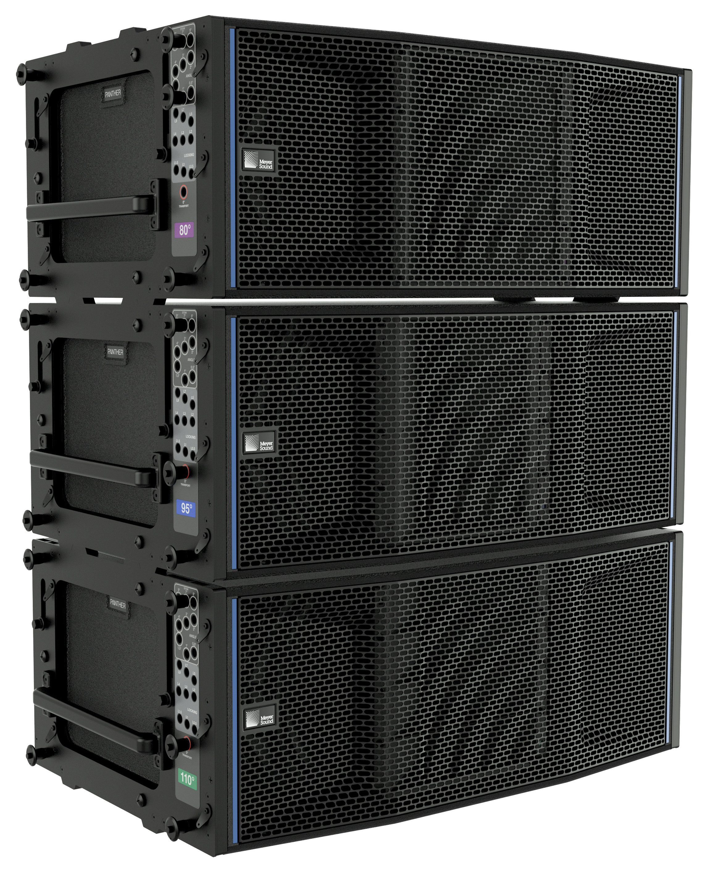
PANTHER Loudspeakers, Three Models Available
The self-powered PANTHER™ linear line array loudspeaker is designed to meet the user needs for a variety of high-power applications.
There are three PANTHER loudspeaker models, each offering a different horizontal dispersion:
PANTHER-L: 80 degrees
PANTHER-M: 95 degrees
PANTHER-W: 110 degrees
PANTHER is designed to be deployed alongside Meyer Sound LFC products, extending the low-frequency performance.
The high-output switch-mode power supply both reduces weight and is more efficient than linear power supplies. The operating voltage is 200-240 V AC, 50-60 Hz.
Both analog and Milan AVB audio inputs are provided on the user panel. All the connectors provided on the user panel are from the Neutrik True Outdoor Protection (TOP) product line. An IP65 rating is achieved for the connectors only when the connected cables are also terminated with Neutrik TOP connectors or when the sealing caps are properly seated.
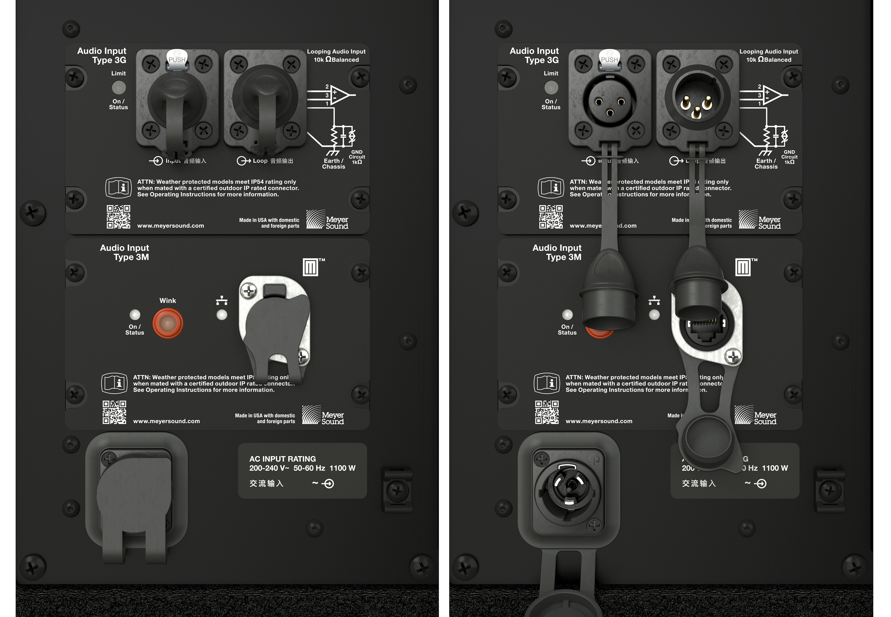
PANTHER User Panel, Seated Sealing Caps, Sealing Caps Open
Meyer Sound’s Nebra software is used to monitor PANTHER telemetry data, which is transmitted via the network connection. The Wink function identifies loudspeakers listed in Nebra.
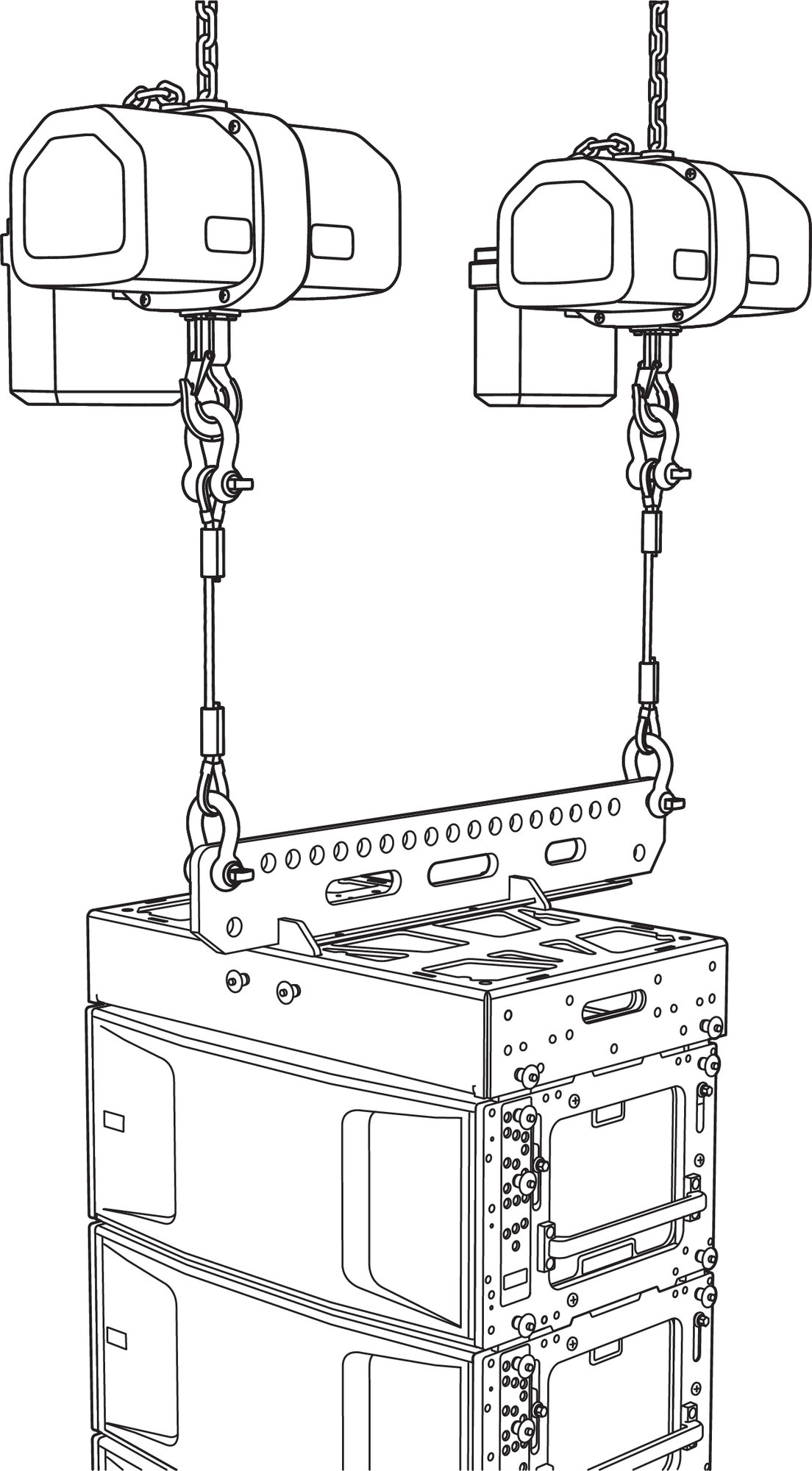
The MG-PANTHER Grid Kit connects the top PANTHER of an array to hoisting equipment. The MG-PANTHER Shackle Bar connects to the MG-PANTHER Grid Box with quick- release pins.
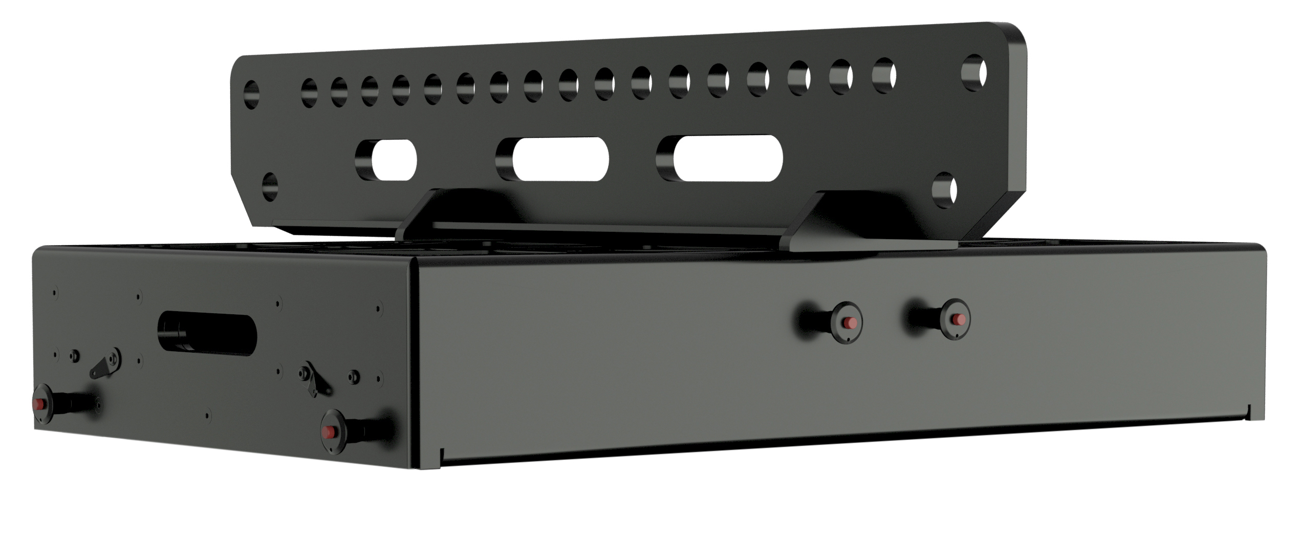
MG-PANTHER Grid Kit
For transporting up to four PANTHER loudspeakers and the MG-PANTHER Grid Box, MCF-PANTHER Caster Frames and four-high covers are available.
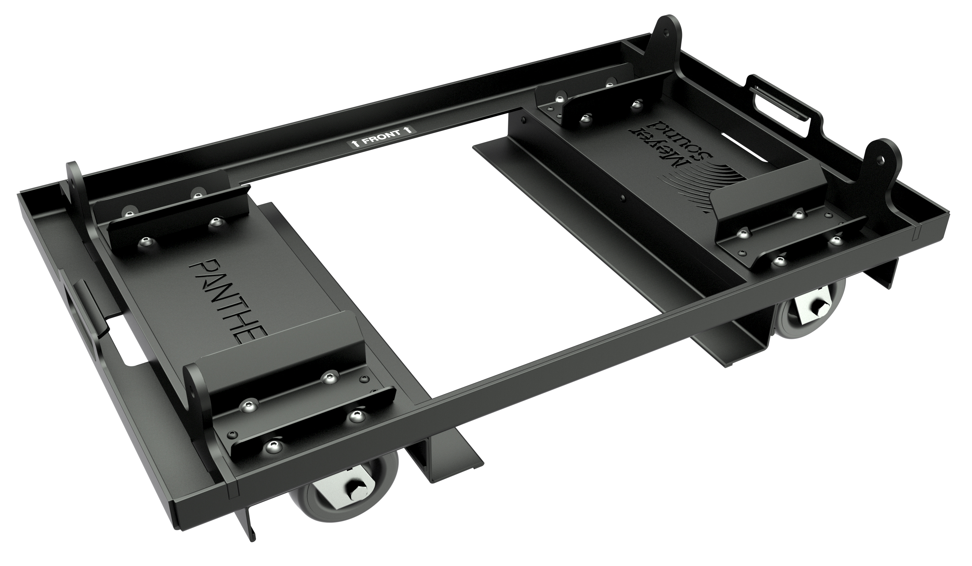
MCF-PANTHER Caster Frame
The PBF-LYON Pull-Back Bar Kit connects the bottom of an array to either a hoist for additional downtilt, or to the MG-PANTHER Shackle Bar via a manual hoist (not included) to aid in array assembly. See page 21 for information.
PBF-LYON Pull-Back Bar Kit
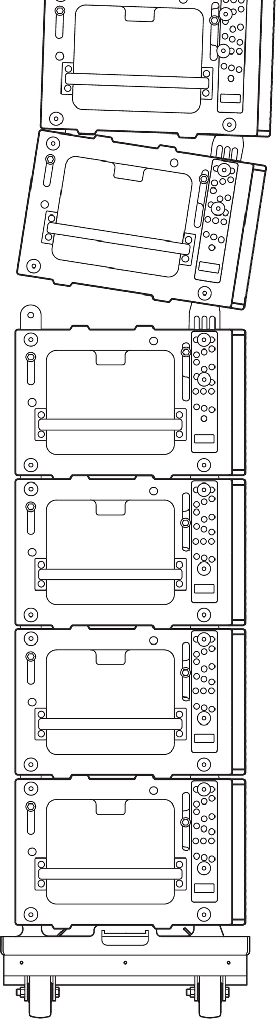
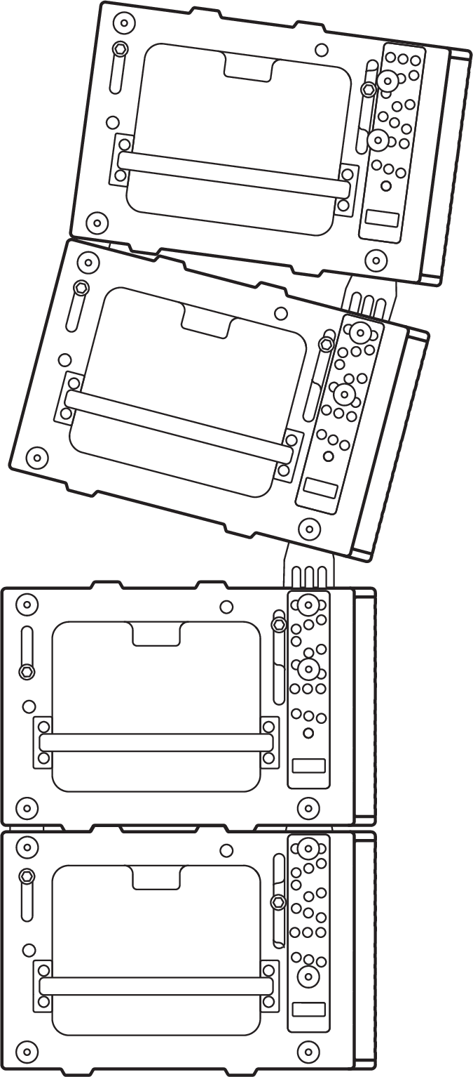
PANTHER Arrays with PBF-LYON in Pull-Up Configuration to Aid in Assembly
PANTHER Arrays with PBF-LYON in Pull-Back Configuration for Additional Downtilt
Safety statement for rigging
READ THIS STATEMENT CAREFULLY IN ITS ENTIRETY |
It contains important information regarding safety issues, including guidelines for general safe use of rigging systems as well as advisories on government regulations and liability laws.
This statement assumes that the owners and/or users of a Meyer Sound QuickFly® system are knowledgeable and experienced in the areas of rigging and flying loudspeaker systems. Many issues of crucial concern, such as the determination of appropriateness and condition of venue rigging points, cannot be addressed here. Therefore, the user must assume all responsibility for the appropriate use of QuickFly systems in any particular location or circumstance.
The suspension of large, heavy objects in public places is subject to numerous laws and regulations at the national/ federal, state/provincial, and local levels. The user must assume responsibility for making sure that use of any QuickFly system and its components in any particular circumstance or venue conforms to all applicable laws and regulations in force at the time.
Power Requirements
Understanding power distribution, voltage and current requirements, and electrical safety guidelines is critical to the safe operation of PANTHER loudspeakers.
Sufficient power must be provided for PANTHER loudspeakers to accurately reproduce the full dynamic range of the input signal, especially during periods of maximum acoustic output.
AC Power Distribution
All components in an audio system (self-powered loudspeakers, mixing consoles, and processors) must be properly connected to an AC power distribution system, ensuring that AC line polarity is preserved. All the grounding points of the audio system components must be connected to a single node or common point using the same cable gauge (or larger) as the Neutral and Line conductors.
Caution
The nominal operational AC mains voltage range is 200–240 V AC.
The voltage between the Earth/Ground and Line should never exceed 264 V AC or be less than 160 V AC
Before applying AC power to any Meyer Sound self-powered loudspeaker, make sure the voltage potential difference between the Neutral and Earth/Ground conductors is less than 5 V AC when using single-line AC wiring (LINE - NEUTRAL - EARTH/GROUND).
The Earth/Ground conductor must always be used for safety reasons.
Improper earthing/grounding of connections between loudspeakers and the rest of the audio system may produce noise or hum or cause serious damage to the input and output stages of the system’s electronic components.
Branch Circuits
To reduce the number of branch circuits, it is common to connect two PANTHER loudspeakers to one branch circuit, provided the circuit breaker is sufficiently rated. To reduce the impedance of the conductors, minimize the length of cable after the branch circuit has been “split.” Typically, a single circuit cable is split very near the loudspeakers using a molded split, junction box, or wye cable to provide power for two PANTHER loudspeakers.
120 V AC, 3-Phase Wye System (Two Lines)
Line-Line-Earth/Ground
The figure below illustrates the secondary of a 120/208 V AC, 3-phase Wye distribution system. Each loudspeaker is connected to two Lines and Earth/Ground. This configuration is possible because PANTHER tolerates elevated voltages from the Earth/Ground conductor and does not require a Neutral line. This distribution system delivers 208 V AC to each loudspeaker.


Three-Phase, 120/208 Volt AC Transformer Secondary, Wye Configuration and Loudspeaker Connections
Caution
Do not connect a PANTHER loudspeaker to only one Line of a 120/208 V AC Wye service as the voltage delivered to the PANTHER loudspeaker will be 120 V AC, which is below the operating voltage range.
230 V AC, 3-Phase Wye System (Single Line)
Line-Neutral-Earth/Ground
The figure below illustrates the secondary of a 230/400 V AC, 3-phase Wye distribution system. Each loudspeaker is connected to one of the Lines, the Neutral, and the Earth/Ground. This distribution system delivers 230 V AC to each loudspeaker.


Three-Phase, 230/400 Volt AC Transformer Secondary, Wye Configuration and Loudspeaker Connections
Caution
For 230/400 V AC, 3-phase Wye systems, never connect two Lines to the AC input of PANTHER. This voltage significantly exceeds the upper voltage limit (264 V AC) and will damage the loudspeaker.
AC Input
The PANTHER user panel includes an AC inlet connector. The 3-conductor Neutrik powerCON TRUE1 True Outdoor Protection (TOP) locking connector supplies electrical power to the loudspeaker, as shown in the figure below.
Caution
The inlet connector is certified for outdoor protection (IP65, UL50E) only when mated with a Neutrik powerCON TRUE1 TOP cable-mount connector, or when the connector is not in use, when the sealing cap is fully inserted.
Check the sealing cap for moisture before covering the connector. If wet, dry the cap before covering the connector to avoid introducing liquid to the connector.
Always seal the connector with the sealing cap when the connector is not in use.

User Panel, Power Inlet, Neutrik powerCON TRUE1 TOP Connector
Caution
Before connecting the power cable, make sure the AC inlet connector assembly is secure and has not been damaged during prior use or transportation.
Assembly of Power Cables
A cable-mount Neutrik powerCON TRUE1 TOP connector is included with each PANTHER loudspeaker (Neutrik NAC3FX-W-TOP) enabling users to assemble power cables to meet their needs.
Caution
For PANTHER power cables, all conductors must be 12 AWG (2.5 mm²)
Use only cable with an outer jacket diameter between 1/4-in [6 mm] and 1/2-in [12 mm]. For the inlet end of the cable, use a plug type that is rated for at least 16A, 250 V AC, and is approved for use in the region where the product will be used.
The pins of the powerCON TRUE1 TOP cable mount connector are labeled as follows:
L (Line)
N (Neutral)
 (Protective Earth or Ground)

Neutrik powerCON TRUE1 TOP Cable Mount Connector
Note
Visit the Neutrik website (neutrik.com) NAC3FX-W-TOP page to download the cable preparation and connector assembly instructions for the powerCON TRUE1 TOP cable-mount connector, document: BDA 541 powerCON TRUE1 TOP – NAC3FXW-TOP.pdf
Caution
Careful attention should be paid when terminating these connectors to ensure the proper conductor of the cable is connected to the intended terminal. The terminal identification markings inside the connector can be difficult to identify. After terminating the cable conductors, we strongly advise using a continuity meter to verify the proper connections are made, preventing a shock hazard and/or damage to the loudspeaker.
How AC power cables are wired is determined by the type of AC power distribution system used (see AC Power Distribution).
Caution
When wiring AC power cables and distribution systems, it is important to preserve AC line polarity and connect the earth ground at both ends of the cable.
PANTHER Voltage Requirements
The AC mains voltage range at the loudspeaker AC inlet must be between 160 V AC and 264 V AC while the loudspeaker is operating, including periods of peak acoustic output when the loudspeaker draws maximum current.
Since PANTHER behaves as a constant power load when TPL (True Power Limiting) is engaged, current increases if the voltage decreases at its AC inlet. The maximum round- trip resistance of the power cable for a single PANTHER should not exceed 5 Ohms for a 230 V AC source voltage because the AC Mains voltage will fall below 160 V AC at the AC inlet when TPL is engaged, or when audio burst or peak power are high.
Caution
PANTHER may be damaged or may malfunction if the inlet voltage is greater than 264 V AC or less than 160 V AC.
Power Supply
The power supply included in PANTHER loudspeakers prevents high inrush currents with soft-start power up, suppresses high-voltage transients up to several kilovolts, and filters common mode and differential mode radio frequencies (EMI).
Powering on PANTHER
When powering on PANTHER loudspeakers, the following startup events take place over several seconds:
The On/Status LEDs flash during initial startup.
When both the On/Status LEDs turn solid green, the loudspeaker is unmuted and ready to reproduce audio.
Caution
If the On/Status LEDs do not turn solid green after 15 seconds, remove AC power and verify that the voltage is within the required range and the conductors of the power cable are connected to the proper terminals of the connectors. If the On/Status LEDs continue to blink or do not illuminate solid green, contact Meyer Sound Technical Support.
Circuit Breaker Requirements
The circuit breakers used in the Meyer Sound MDM-5000 are well suited for use with PANTHER loudspeakers and other Meyer Sound products:
European MDM-5000 includes ETI model number: KZS-1M 1p+N A C16/0.03, 6kA, which includes an RCD (residual current device) with a C-type tripping time constant and 30 mA RCD.
US MDM-5000 includes Eaton model: QCR2020 - CIRCUIT BREAKER 2-Pole, 20 A, 120/240 V AC
Circuit protection devices for main and branch circuits of any power distribution system used in conjunction with PANTHER loudspeakers should use similarly specified devices to avoid nuisance tripping.
Note
Many RCCB’s (residual current circuit breakers) are sensitive to high-frequency noise in the Line-Neutral path and may false/nuisance trip. If required, make certain the residual current device is not sensitive to high-frequency noise or artifacts. Line-to-Ground and Neutral-to- Earth/Ground capacitance can cause an imbalance between the current carrying conductors in a cable or a conduit, potentially causing RCCB nuisance tripping. Consult with a licensed electrician or electrical engineer when designing electrical distribution systems.
Electrical Safety Guidelines
Make sure to observe the following important electrical and safety guidelines.
Do not operate the unit if the power cable is frayed or broken.
Use the cable rings on the rear of the PANTHER cabinet to reduce strain on the chassis and cable connectors (see Figure 16). Do not use the cable rings for any other purpose.
Amplification and Audio
The user panel located on the rear of PANTHER loudspeakers includes audio input connectors, one for analog audio, the other for Milan AVB digital audio.
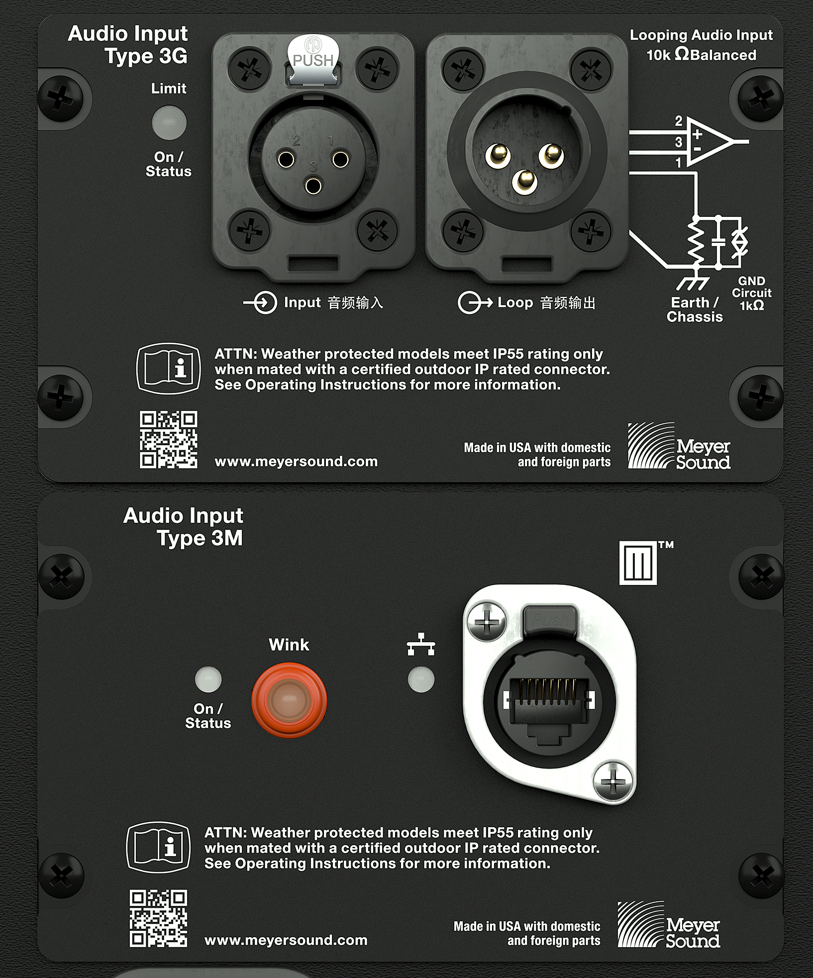
PANTHER User Panel, Audio Inputs (Sealing Caps Not Shown)
Both audio inputs are always active. If signal is present at both inputs, they are summed and reproduced, which can lead to undesired results. For example, if the Milan and analog input signals are identical for backup purposes, but are not time aligned, comb filtering will occur if both signals are present at the loudspeaker inputs. When using one input as a backup to the other, utilizing the mutes of upstream signal processing is one strategy to switch between input types.
Note
Using Groups and Controls in Compass, a single control button can be assigned to toggle some or all the input or output mutes of a Galileo GALAXY processor or processors.
The analog and Milan inputs will arrive at the loudspeaker at different times due to the transport time of the Milan signal through the network, usually less than 2 ms. The latency of the Milan signal is dependent on the number of network switch hops and the presentation time set in software.
To synchronize the audio reproduction of analog and Milan inputs, measure the acoustic output with an FFT analyzer. Measure and store the phase response when only the Milan input is receiving signal. While only the analog input is receiving signal, add delay to the analog signal processing until both phase responses match.
When one input is used as a backup, synchronizing it with the primary input provides a smoother transition when the signal to the primary input is muted and the backup is unmuted. Synchronizing the inputs also preserves the time alignment with other components of the system, regardless of which input is receiving signal.
Audio Connectors
The user panel includes two 3-pin Neutrik XLR True Outdoor Protection (TOP) connectors for analog audio input and audio loop output. The network connector is a Neutrik etherCON True Outdoor Protection (TOP).
Caution
The analog and network chassis connectors are certified for outdoor protection (IP65, UL50E) only when mated with the Neutrik TOP cable-mount connectors, or the sealing caps are fully inserted.
Check the sealing caps for moisture before covering the connectors. If wet, dry the caps before covering the connectors to avoid introducing liquid into the connectors.
Always seal the connectors with the sealing caps when the connectors are not in use.
Analog Audio Input (XLR 3-Pin Female)
The XLR 3-pin female Input connector accepts balanced audio signals with an input impedance of 10 kOhm. The connector uses the following wiring scheme:
Pin 1 — 1 kOhm to chassis and earth ground (ESD clamped)
Pin 2 — Signal (+)
Pin 3 — Signal (–)
Case — Earth (AC) ground and chassis
Pins 2 and 3 carry the input as a differential signal. Pin 1 is connected to earth through a 1 kOhm, 1000 pF, 15 V clamped network. This circuitry provides a virtual ground lift for audio frequencies while allowing unwanted signals to bleed to ground. Make sure to use balanced XLR audio cables with pins 1, 2, and 3 connected on both ends. Connecting the signal ground at only one end is not recommended. Shorting the signal ground conductor to the connector case may cause a ground loop, resulting in hum
Note
If unwanted noise or hiss is produced by the loudspeaker, disconnect the audio signal cable from the loudspeaker input. If the noise stops, there is most likely nothing wrong with the loudspeaker. To locate the source of the noise, check the audio cable, source audio, AC power, and electrical ground.
Analog Audio Loop Output (XLR 3-Pin Male)
The XLR 3-pin male Loop output connector allows multiple loudspeakers to be looped from a single audio source. The Loop output connector uses the same wiring scheme as the Input connector. For applications that require one drive line to provide signal to multiple PANTHER loudspeakers, connect the Loop output of the first loudspeaker to the Input of the next loudspeaker, and so forth.
Note
The Loop output connector is wired in parallel to the Input connector and transmits the unbuffered source signal even when the loudspeaker is powered off.
Calculating Analog Input Load Impedance
To avoid distortion when looping multiple loudspeakers, make sure the source device can drive the total load impedance of the looped loudspeakers. In addition, the source device must be capable of producing +24 dBu into 50 Ohms to produce the maximum peak SPL over the operating bandwidth of the loudspeaker.
Tip
Audio outputs from Meyer Sound’s Galileo GALAXY Network Platform have an output impedance of 50 ohms. Each output can drive up to 20 Meyer Sound (10 kOhm input) loudspeakers without distortion.
To calculate the load impedance for the looped loudspeakers, divide 10 kOhms (the input impedance for a single loudspeaker) by the number of looped loudspeakers. For example, the load impedance for ten PANTHER loudspeakers is 1 kOhms (10 kOhms / 10). Most source devices are capable of driving loads no less than 10 times their output impedance. To drive this number of looped loudspeakers, the source device should have an output impedance of 100 ohms or less (1000 ohms / 10).
Caution
Make sure all cabling for looped loudspeakers is wired correctly (Pin 1 to Pin 1, Pin 2 to Pin 2, and so forth) to prevent the polarity from being unintentionally reversed. If one or more loudspeakers in a system receive audio signals that are of the opposite polarity, frequency response and coverage will be significantly degraded.
Network Connector
The user panel includes a Milan Endpoint (MEP) module, shown in the figure below, which includes a Neutrik etherCON TOP connector, an Ethernet connectivity LED, an On/Status LED, and a Wink button/LED.
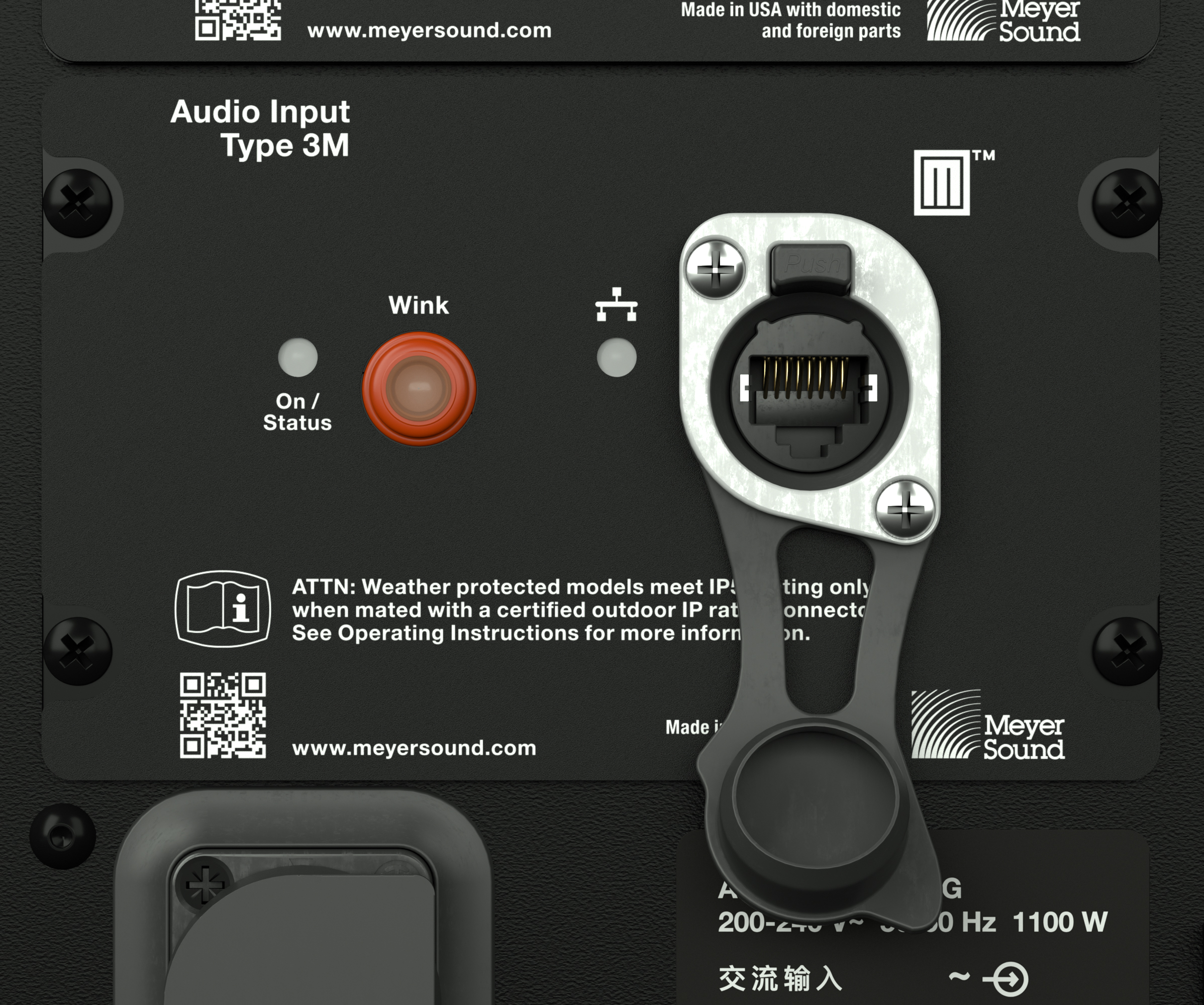
PANTHER User Panel MEP, etherCON TOP Connector
The etherCON TOP connector provides the network connection for transmission of a Milan AVB digital audio signal to the loudspeaker and the transmission of telemetry data from the loudspeaker.
The Milan Endpoint connects to a single channel of a Milan digital audio stream as specified by the Avnu Alliance. To utilize the Milan input, connect the loudspeaker to an Avnu-certified network switch. See avnu.org for the current listing of certified AVB network switches.
The telemetry data of the loudspeaker is also transmitted via this connector, which is displayed in Nebra software. An Avnu-certified switch is not necessary when the network connection is only used to transmit telemetry data. The speed of this network connection is 100 bT, 100 Mb/ second.
Digital Audio Input
When a Milan Endpoint loudspeaker and a computer are connected to the same network via an Avnu-certified network switch, the loudspeaker will be listed in Meyer Sound’s Nebra software where Milan AVB connections are established. The Milan Endpoint loudspeaker must be assigned to an available audio source channel (Talker) as a Listener in order for the loudspeaker to reproduce the audio transmitted by the Talker. The speed of the connection between the last network switch and a Milan Endpoint is 100 bT, 100 Mb/ second. The connection speed between network switches transporting Milan digital audio signals is 1000 bT, 1 Gb/second.
Telemetry
Loudspeakers with Milan Endpoints transmit telemetry data via the network connection. When Milan Endpoint equipped loudspeakers are connected to a computer via a network switch, the loudspeaker telemetry data is displayed in Meyer Sound’s Nebra software.
Tip
Use an Avnu-certified network switch when the Milan digital audio input is used. For a list of Avnu-certified AVB switches, please refer to the certification pages at avnu.org. When the Milan input is not used, a standard Ethernet network (IEEE 802.3 compliant, supporting at least 100 MB/s, full-duplex) is capable of transmitting the telemetry data.
Nebra software displays system status and performance data for each loudspeaker, including amplifier voltage, limiting activity, power output, fan speed, and driver status. A mute function is also available.
Wink Function
The Wink function facilitates the identification of physical loudspeakers that are listed in Meyer Sound’s Nebra software. When routing digital audio signals in software between an output device and a loudspeaker, the loudspeaker name needs to properly indicate which physical loudspeaker will receive the signal.
There are three locations Wink is indicated: Nebra software, the Wink button/LED on the user panel of the loudspeaker, and two LED strips on the front of the PANTHER cabinet.
Once the Milan Endpoint has been discovered in Nebra software, the icons within the loudspeaker’s detail page include a button with an icon of an eye. Double-clicking the icon in Nebra software toggles the Wink function. When the Wink function is active, the Wink button/LED on the user panel of the loudspeaker and the two LED strips on the front of the loudspeaker also illuminate. The Wink function times out after 10 seconds.
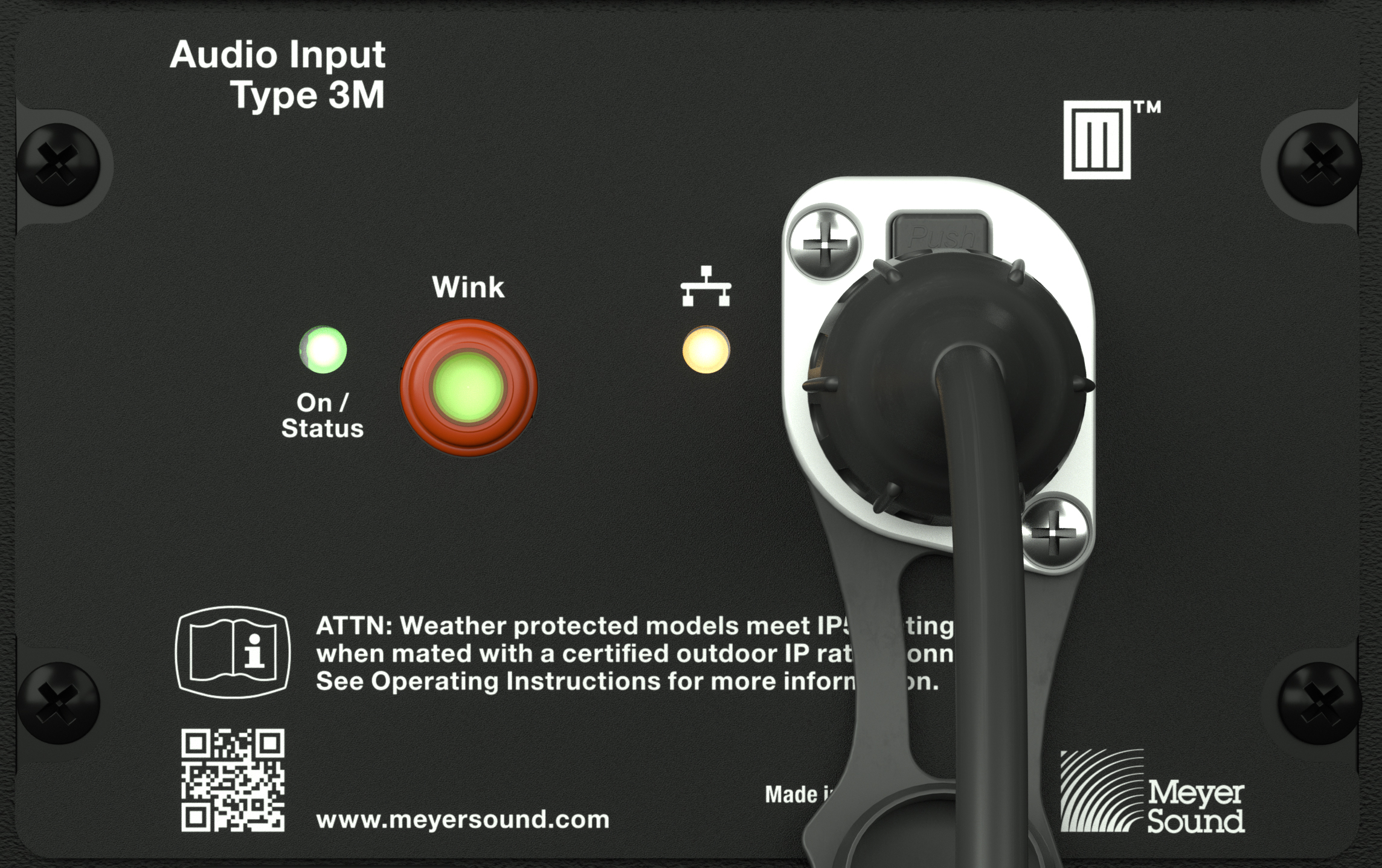
On/Status LED, Wink Button/LED, Network Connectivity LED, and Network Connector.
Wink/Activity LED Button
To activate the Wink function from the loudspeaker, press and hold the Wink button down while observing the On/Status LED, which turns red and then off. Release the Wink button when the On/Status LED turns off, activating the Wink function. The Wink LED turns green for 10 seconds. If the Wink button remains depressed, the On/ Status LED will turn red again and the Wink function will remain off.
To turn off the Wink function, wait 10 seconds for it to time out or depress and hold the Wink button, the On/Status LED will turn red. Wait until the On/Safety LED turns off, then release the Wink button.
Ethernet/Network Connectivity LED
The Ethernet/Network connectivity LED, shown below, is illuminated when a 100 bT link is established; otherwise, it is off.
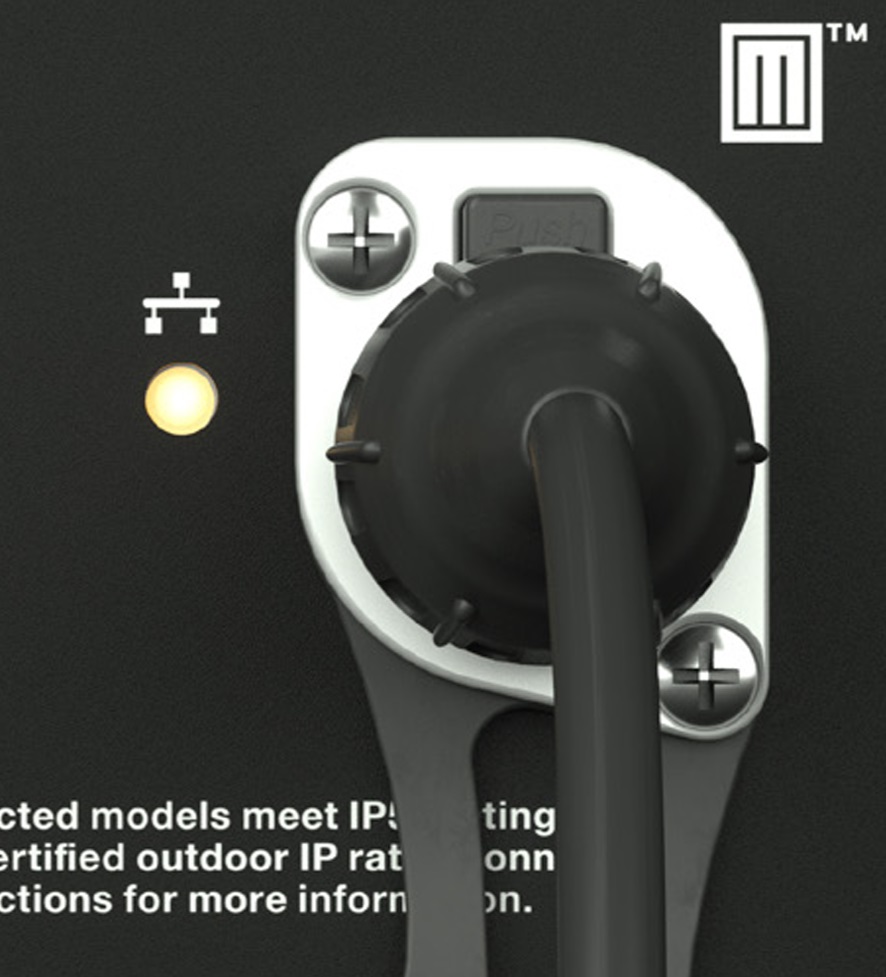 |
On/Status LED, Wink Button/LED, Network Connectivity LED, and Network Connector.
On/Status and Limiting Indication
When powered on, the On/Status LED blinks many times, then turns solid green. During normal operation, the On/Status LED is solid green. If either of the On/Status LEDs blink red after the startup sequence, there is an issue to address. Connect the loudspeaker to a computer running Nebra software to identify the issue.
Limiting activity is indicated when the On/Status LED on the user panel turns from green to yellow, solid yellow for 1 second when the high-frequency channels limit and pulsing yellow when the low-frequency channels limit.
When limiting is engaged, the channel’s gain is reduced. The limiter protects the drivers and prevents signal peaks from causing excessive distortion in the amplifier, thereby preserving headroom and maintaining a smooth frequency response at high levels. When source levels return to normal, below the limiter’s threshold, the LED turns green and limiting ceases.
The loudspeaker performs within its acoustical specifications at normal temperatures when the On/Status LED is green, or when limiting is not continuous. During continuous limiting, the loudspeaker is nearing its operational limits, resulting in the following effects:
Increases to the input level have no effect
Distortion increases due to clipping and nonlinear driver operation.
The drivers are subjected to excessive heat and excursion, which compromises their life span and may eventually damage them.
Caution
The On/Status LED indicates when a safe, optimum level is exceeded. If a PANTHER loudspeaker system begins to limit before reaching the desired acoustic output, consider adding more loudspeakers to the system.
Amplifier Cooling System
PANTHER loudspeakers employ forced-air cooling to prevent overheating. Two variable-speed fans pull air through the vents located on the bottom of the cabinet and below the user panel (see the figure below). These vents have internal foam to capture any particulate. Most of the air passes over the heat sinks underneath the air cowl. The remainder passes through a fine wire mesh and enters the amplifier module.
Caution
To keep PANTHER from overheating, allow at least six inches (15 cm) of space with unobstructed airflow behind the enclosure for proper ventilation.
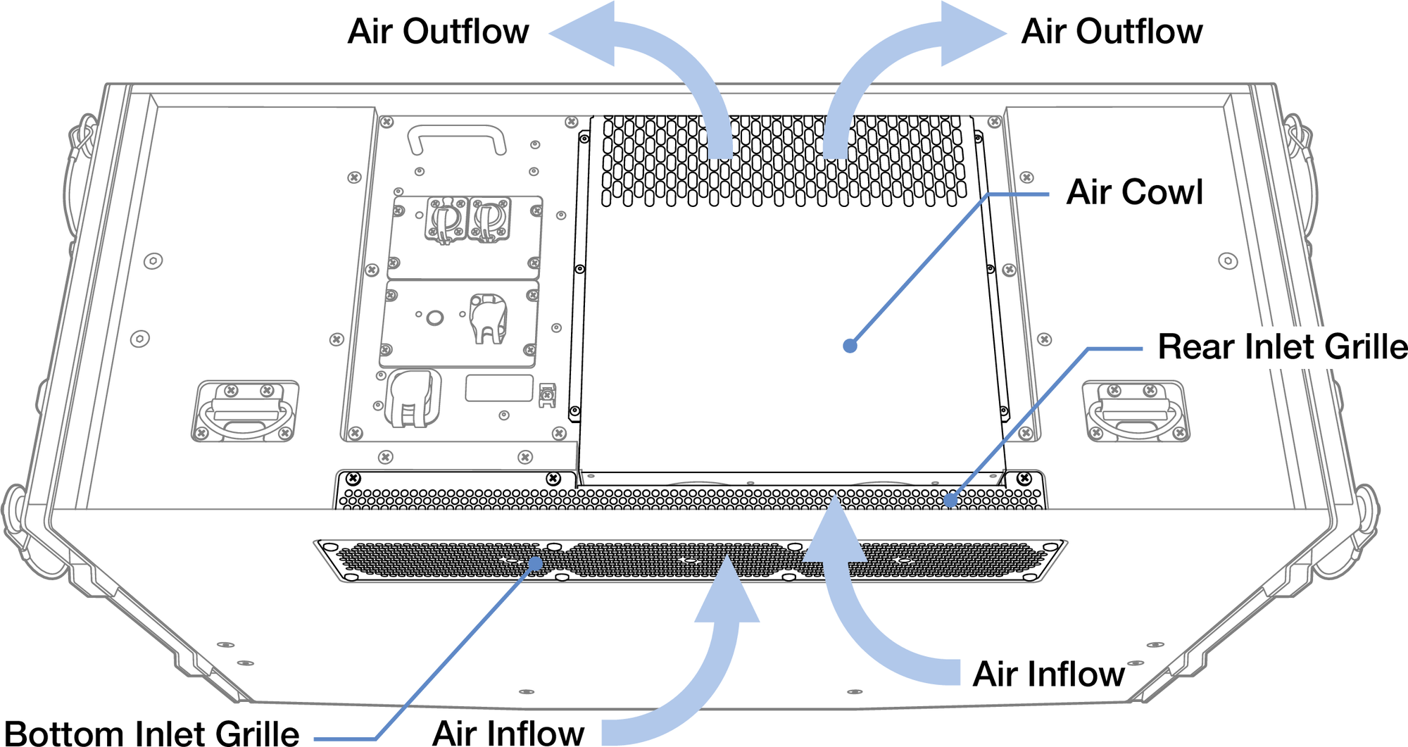
PANTHER Amplifier Ventilation
Caution
Regularly inspect the foam behind the air intake grilles located on the bottom of the cabinet and below the user panel. If a significant amount particulate has accumulated on the foam, remove the intake grilles (not the air cowl covering the heat sinks), then the foam. Vacuum and then rinse the foam with water until the particulate is removed. Allow the foam to dry completely, then reassemble.
Tip
When PANTHER is connected to a network, Meyer Sound’s Nebra software displays telemetry metrics, including the fan status and operating temperature.
Cable Rings
Two cable rings are provided on the rear of the PANTHER cabinet, as shown in the figure below. Power and audio cables should be tied off to these rings to reduce strain and prevent damage to them and the chassis mounted connectors.
Caution
Cable rings should only be used to reduce strain on cables and not be used for any other purpose.

Cables Tied Off to Cable Ring
PANTHER Rigging
PANTHER Rigging Accessories
The available rigging accessories and PANTHER loudspeakers are listed in the table below.
Model | Weight | Features | Required Quick-Release Pins | Required Shackles |
|---|---|---|---|---|
PANTHER Loudspeaker | 150 lb (68 kg) | Includes end-frames and GuideALinks secured with custom quick-release pins (QRP) for connections to other cabinets and rigging accessories. | 7/16 x 0.9-inch QRP (black button) with lanyard PN 134.065 qty 10 included | (none required) |
MVP Motor V Plate (PN 40.215.184.01) | 20 lb (9.1 kg) | Fine tunes the horizontal aim of arrays; compatible with other Meyer Sound products. | 3/4-inch or 7/8- inch | |
MG-PANTHER Grid Kit (PN 40.324.400.01) | 210 lb (95.3 kg) | With some restrictions, can support up to 25 PANTHER loudspeakers at a 5:1 safety factor. Kit includes MG-PANTHER Grid Box (PN 45.324.400.01) and MG-PANTHER Shackle Bar (PN 45.324.405.01). | 1/2 x 1.5-inch QRP (red button) with lanyard PN 134.045 qty 4 included and 7/16 x 1.5-inch QRP (red button) with lanyard PN 134.051 qty 4 included | 3/4-inch or 7/8- inch |
PBF-LYON Pull-Back Frame (PN 40.232.125.01) | 9.5 lb (4.3 kg) | Attaches to the bottom cabinet of PANTHER arrays and provides pull-back for extreme array downtilt; can also be used for pull-up to expand the array’s splay angles during installation so the LOCK pins can be more easily inserted. | This accessory is secured with the quick-release pins included with each PANTHER cabinet. | 5/8-inch |
MCF-PANTHER Caster Frame (PN 40.324.200.01) | 105 lb (68 kg) | Safely transports up to four PANTHER cabinets and the MG-PANTHER Grid Box (without the Shackle Bar) allowing assembly and disassembly of arrays in blocks of four cabinets. | This accessory is secured with the quick-release pins included with each PANTHER cabinet. | (none required) |
MTF-LYON/LEOPARD Transition Frame Kit (PN 40.232.140.01) | 71 lbs (32.2 kg) | Attaches to the bottom cabinet of PANTHER arrays to add LEOPARD loudspeakers below. With some restrictions, up to 10 LEOPARD at a 5:1 safety factor. | 5/16 x .0875-inch QRP (red button) with lanyard PN 134.025 qty 8 included | (none required) |
Note
The MCF-PANTHER Caster Frame and PBF-LYON Pull-Back Frame do not include quick-release pins. These accessories are secured with the quick-release pins included with each PANTHER cabinet.
Caution
Always model each array configuration in Meyer Sound’s MAPP System Design and Prediction software to determine if the array configuration is within safety limits (5:1 safety factor). Do not suspend an array when the Safety Limits Analysis in MAPP displays “Configuration has exceeded the rated load capacity.”
The PANTHER QuickFly rigging system includes custom quick-release pins. When assembling a PANTHER array, use only quick-release pins acquired from Meyer Sound to secure the connecting hardware (GuideALinks) and rigging accessories.
MVP Motor V Plate
The optional MVP Motor V Plate can be used to adjust the horizontal aim of PANTHER arrays up to ±18°.
MVP Motor V Plate Kit Contents
Quantity | Part Number | |
|---|---|---|
 | 1 | 45.215.184.01 |
The MVP Motor V Plate has the following load ratings:
5:1 | |
|---|---|
Maximum Number of PANTHER Loudspeakers + MG-PANTHER Grid Kit | 25 |
MVP Motor V Plate Overview
The top of the MVP Motor V Plate is connected to two hoists. The bottom of the MVP Motor V Plate connects to the MG-PANTHER Shackle Bar front or rear points (1 or 19).
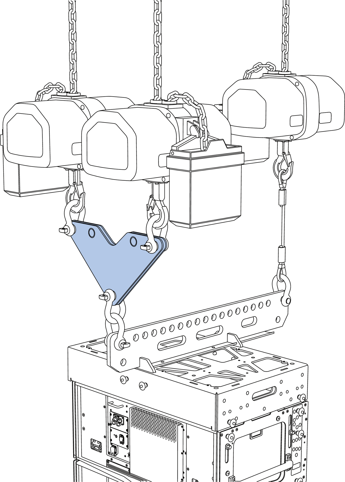 |
MVP-Motor V Plate, MG-PANTHER Grid Kit, PANTHER Loudspeakers
When the hoists are adjusted, the horizontal aim of the array is changed.
MVP-Motor V Plate, Pulling Up on Either Motor Rotates the Array
Caution
When assembling, disassembling, raising or lowering an array, always equalize the loading of the hoists connected to the MVP Motor V Plate. When the array is at the desired height and the grid has been tilted to the desired angle, adjust the hoists connected to the MVP Motor V Plate to achieve the desired horizontal rotation.
Always use sufficiently rated rigging hardware, e.g., wire rope, shackles, hoists, etc. for connections above and below the MVP Motor V Plate.
The two inner, top holes of the MVP Motor V Plate are not used for hoist attachment. These provide structural support for the front and rear plates of the accessory.
Note
The MVP Motor V Plate requires 3/4-inch or 7/8-inch shackles for its attachment points.
See Assembling Arrays and Disassembling Arrays for instructions.
MG-PANTHER Grid Kit
The MG-PANTHER Grid Kit provides mechanical connection between hoisting mechanism(s) and PANTHER cabinets.
Hoists, MG-PANTHER Grid Kit, and PANTHER Cabinets
MG-PANTHER Grid Kit Contents
Image | Qty | Part Number | Description |
|---|---|---|---|
 | 1 | 45.324.400.01 | MG-PANTHER Grid Box |
 | 1 | 45.324.405.01 | MG-PANTHER Shackle Bar |
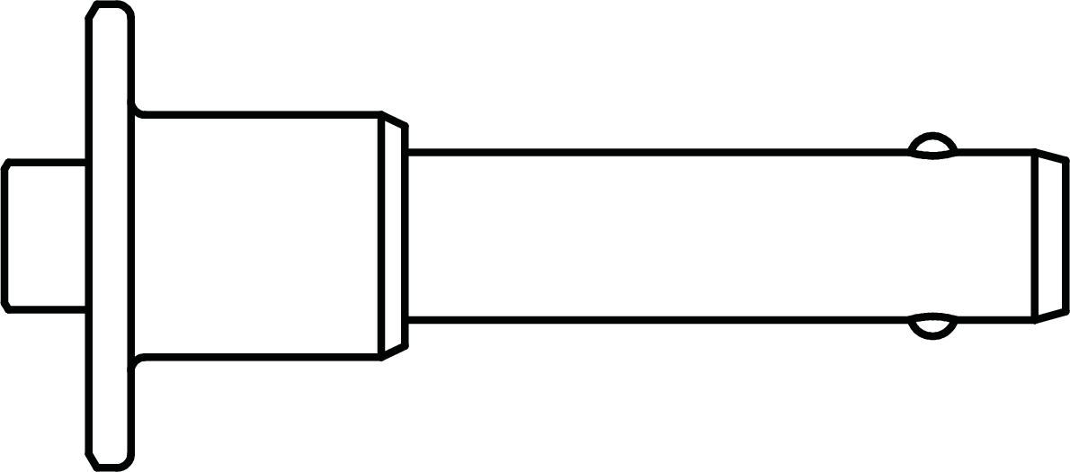 | 4 | 134.045 | 1/2 x 1.5-inch QRP with lanyard (red button) |
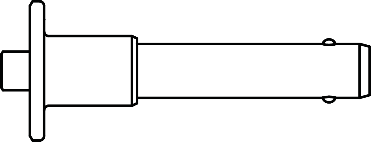 | 4 | 134.051 | 7/16 x 1.5-inch QRP with lanyard (red button) |
Description | Weight |
|---|---|
MG-PANTHER Shackle Bar | 72 lb (37.7 kg) |
MG-PANTHER Grid Box | 138 lb (62.6 kg) |
Table 5. MG-PANTHER Weights
Caution
Ensure the quick-release pins are fully inserted and locked during array assembly.
Always use the 1/2 x 1.50-inch QRP (red button, PN 134.045) included with the MG-PANTHER Grid Box to secure the MG-PANTHER Shackle Bar to the MG-PANTHER Grid Box.
Always use the 7/16 x 1.50-inch QRP (red button, PN 134.051) pins included with the MG-PANTHER Grid Box to secure the MG-PANTHER Grid Box to the top PANTHER loudspeaker. Do not use the quick-release pins included with PANTHER loudspeaker as they are shorter and will not lock in place.
Always use properly rated rigging hardware, e.g., wire rope, shackles, hoists, etc. The MG-PANTHER Shackle Bar requires 3/4-inch or 7/8-inch shackles for its pickup points.
Do not transport 4-high stacks of PANTHER with the MG-PANTHER Shackle Bar attached to the MG-PANTHER Grid Box. This exceeds the safety limits for tip-over, which may cause injury.
Tip
When transporting 4-high stacks of PANTHER on MCF-PANTHER caster frames, the MG-PANTHER Grid Box can remain on top.
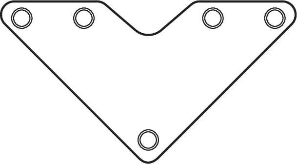
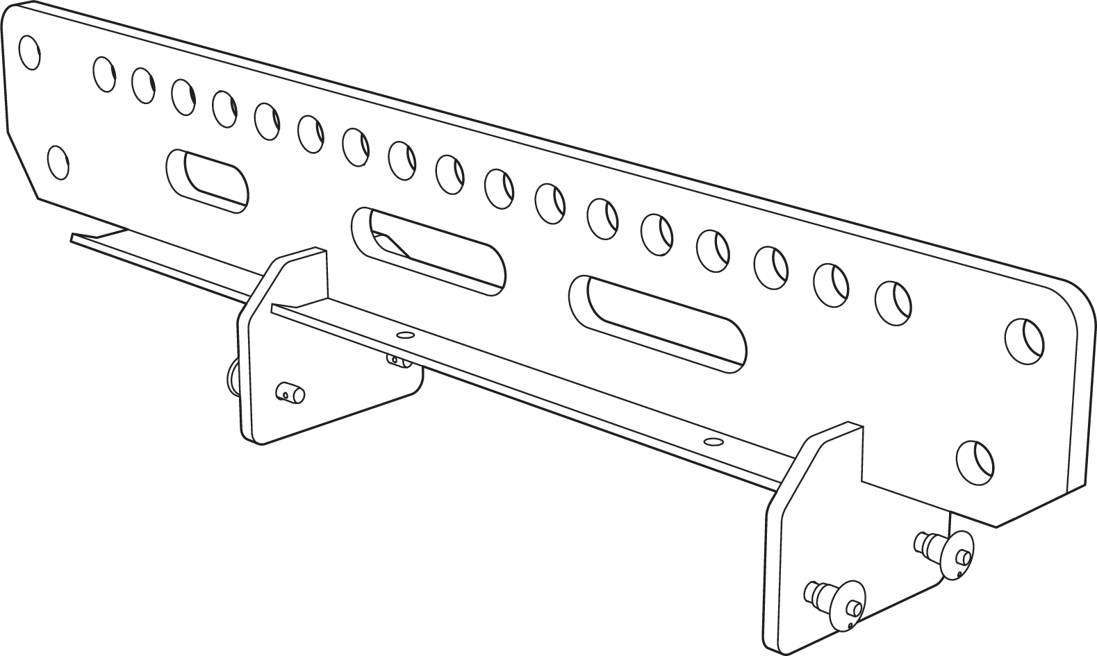
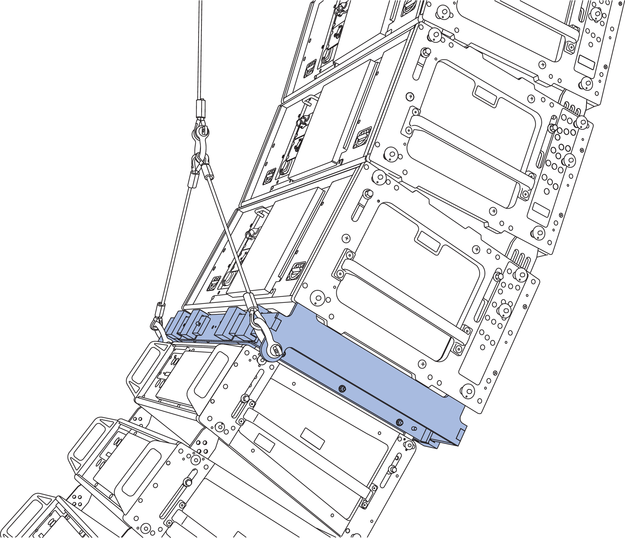
MG-PANTHER Shackle Bar
The MG-PANTHER Shackle Bar is attached to the MG-PANTHER Grid Box with four 1/2 x 1.50-inch QRP (red button, PN 134.045) pins that are secured to the MG-PANTHER Grid Box with lanyards. These quick-release pins are not interchangeable with any other pins used with a PANTHER array.
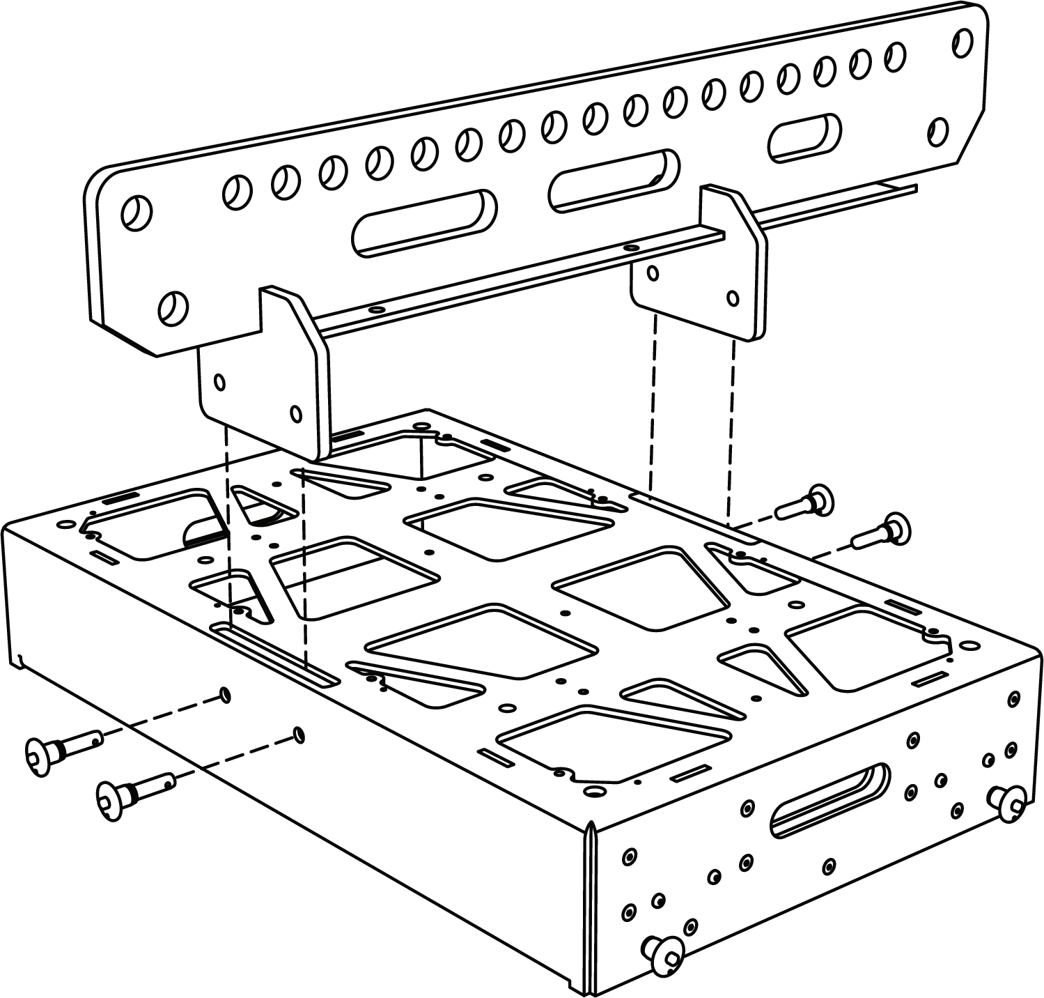
MG-PANTHER Grid Kit, Not Assembled
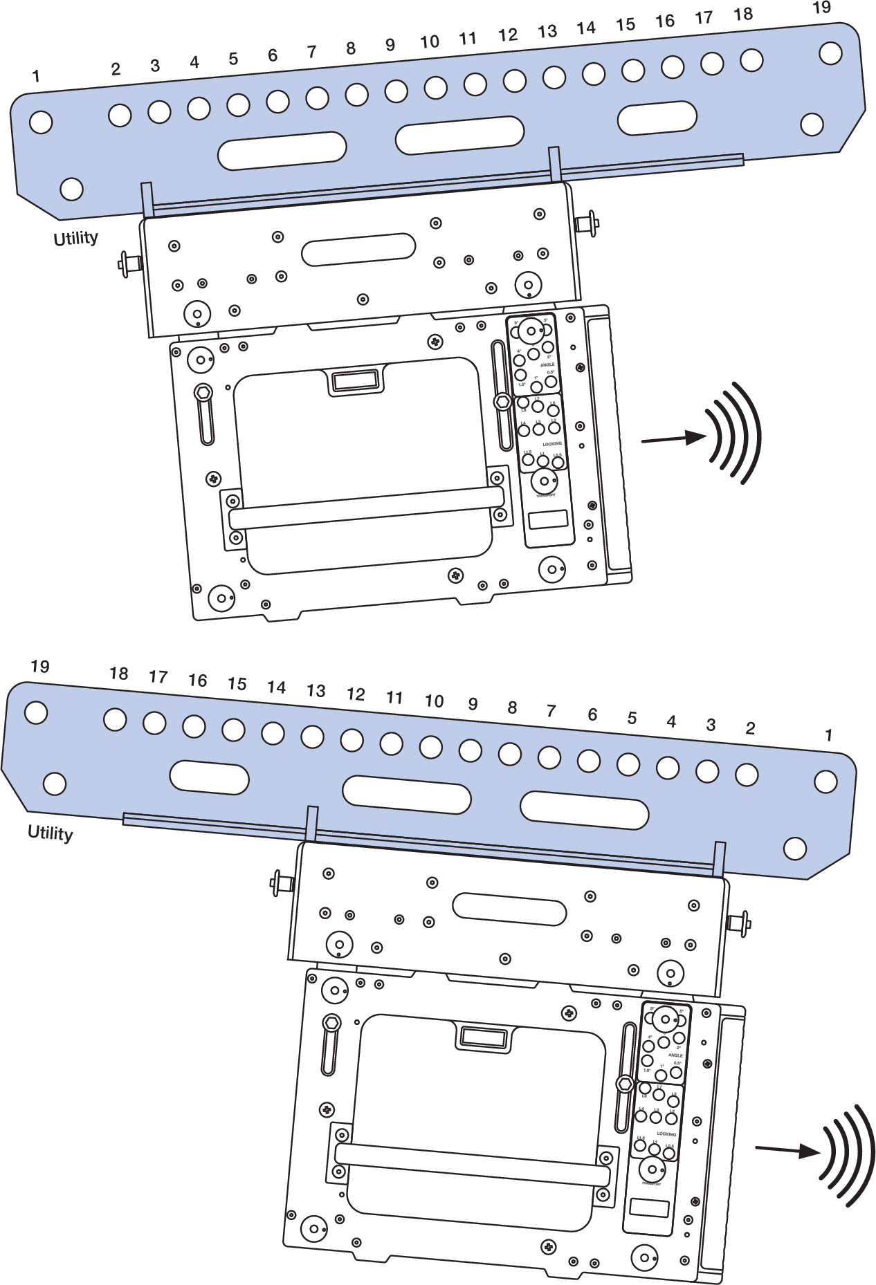
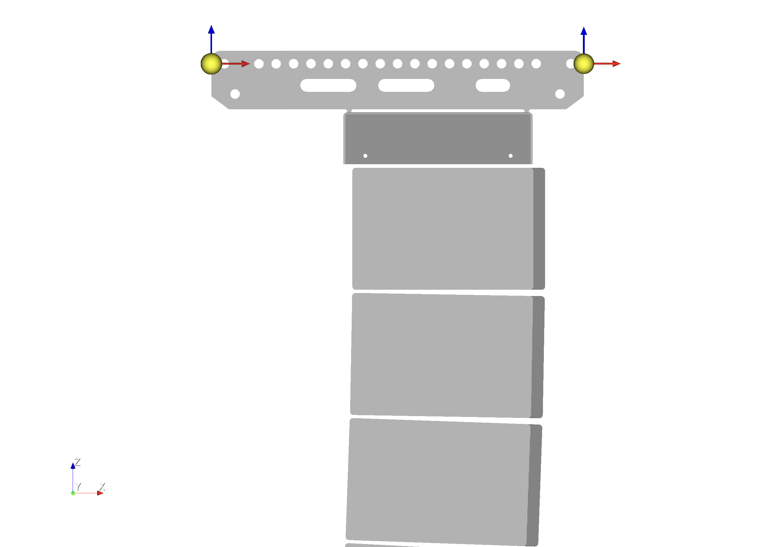
The top row of holes labeled 1 through 19 in Figure 21 below, are provided for connection to hoists. Use holes 1 and 19 when connecting two hoists. Two utility connection points (one at each end) are provided to connect cable picks and/or the chain of the pull-up mechanism (see PBF-LYON).
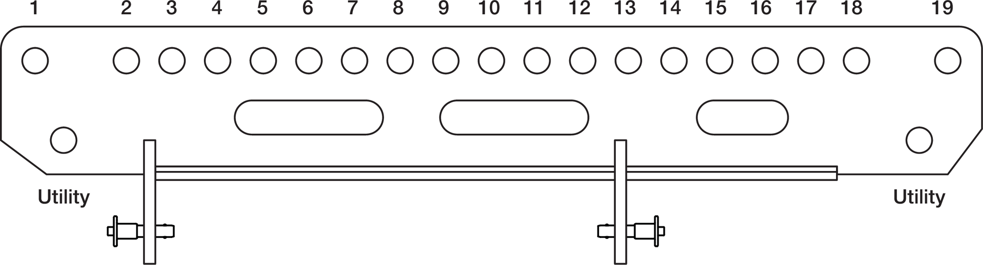
MG-PANTHER Shackle Bar
Caution
The points labeled “Utility” are never used to suspend an array
Tip
It may be convenient to store and transport both the MG-PANTHER Shackle Bar and PBF-LYON in a cable trunk that includes the cabling for an array.
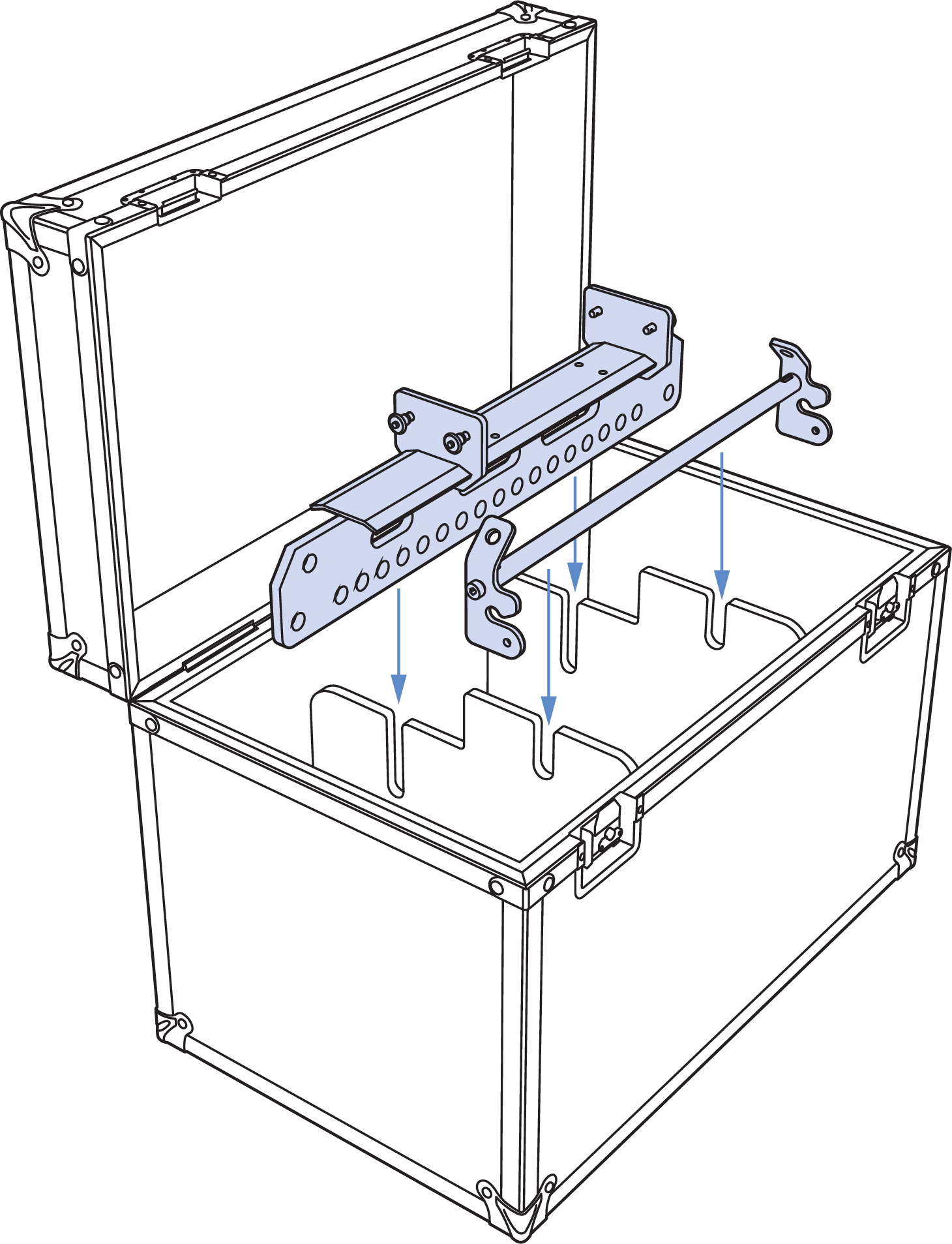
Cable Trunk Example for Accessory Storage and Transportation
MG-PANTHER Grid Box
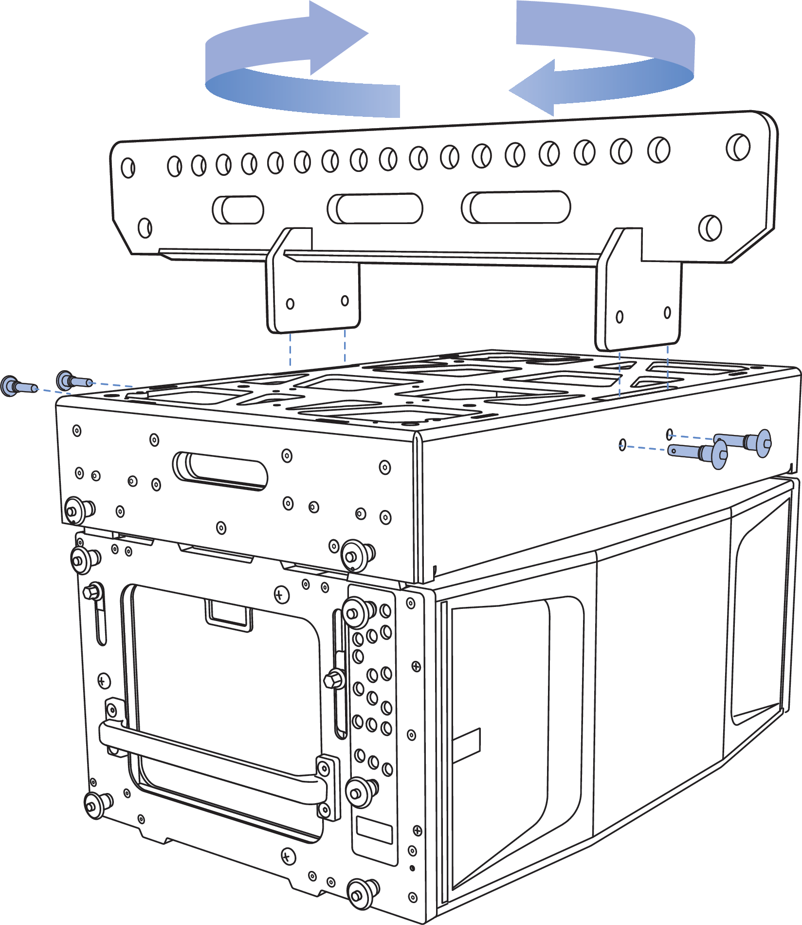
The MG-PANTHER Grid Box is symmetrical and can be connected to the top PANTHER cabinet in either orientation.
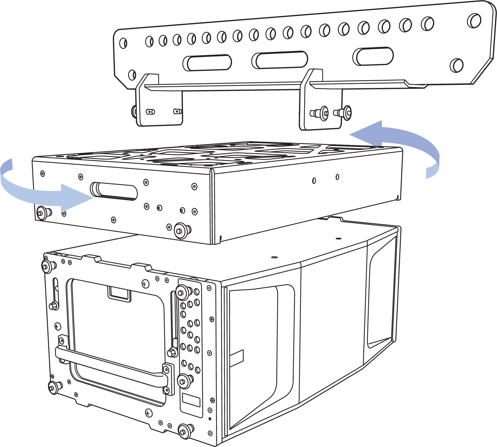
MG-PANTHER Grid Kit and PANTHER Cabinet, MG-PANTHER Grid Box is Symmetrical, Attached to the PANTHER in Either Orientation
The MG-PANTHER Grid Box is connected to the top PANTHER of an array with four 7/16 x 1.50-inch QRP (red button, PN 134.051) pins that are secured to the MG-PANTHER Grid Box with lanyards. These quick-release pins are not interchangeable with any other pins used with a PANTHER array.
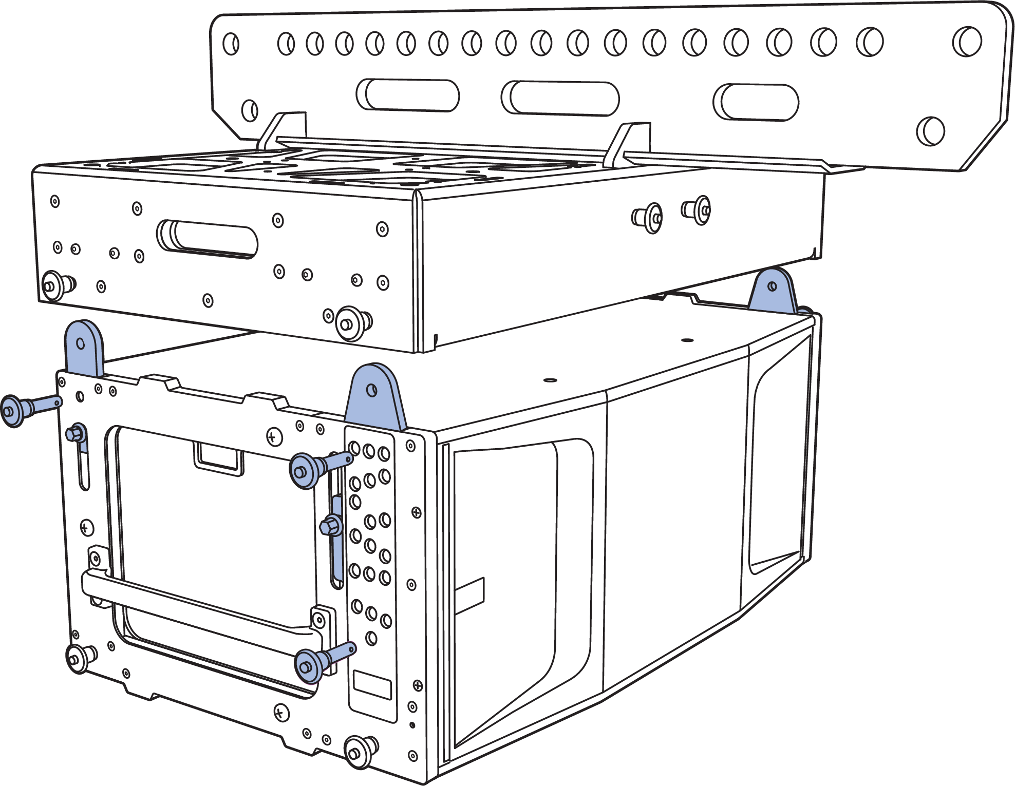
MG-PANTHER Grid Box Connection to Top PANTHER Cabinet
Several attachment points for third-party accessories or equipment racks are available on the top of the MG-PANTHER Grid Box, see the figure below. For accessories weighing more than 50 lb (23 kg), please contact Technical Support before designing or mounting the accessory.
The locations labeled “B” can be used to stow the quick-release pins used to secure the MG-PANTHER Shackle Bar when not in use. The locations labeled “C” align with the mounting holes of third-party brackets used to secure laser/ inclinometers, e.g., ProSight and ProSight2 mounts. Holes labeled “A” and “D” can accommodate the mounting of custom accessories.
For dimensional information, please refer to the CAD (.dwg) drawings available at meyersound.com.
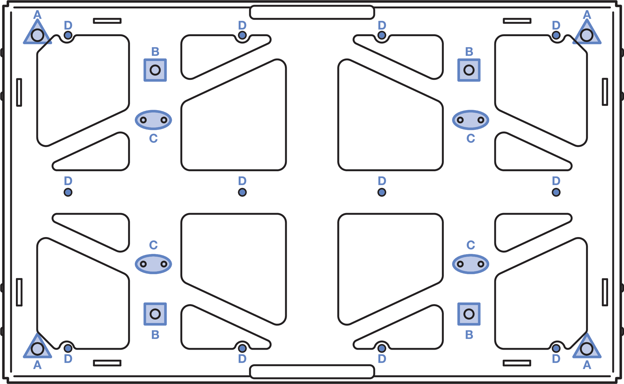
MG-PANTHER Grid Box, Top View
Single-Point Rigging
When suspending an array from a single point of the
MG-PANTHER Shackle Bar, connect the hoist to any hole, 1 through 19. The tilt of the MG-PANTHER Grid Kit is
determined by which hole of the MG-PANTHER Shackle Bar the hoist is connected to.
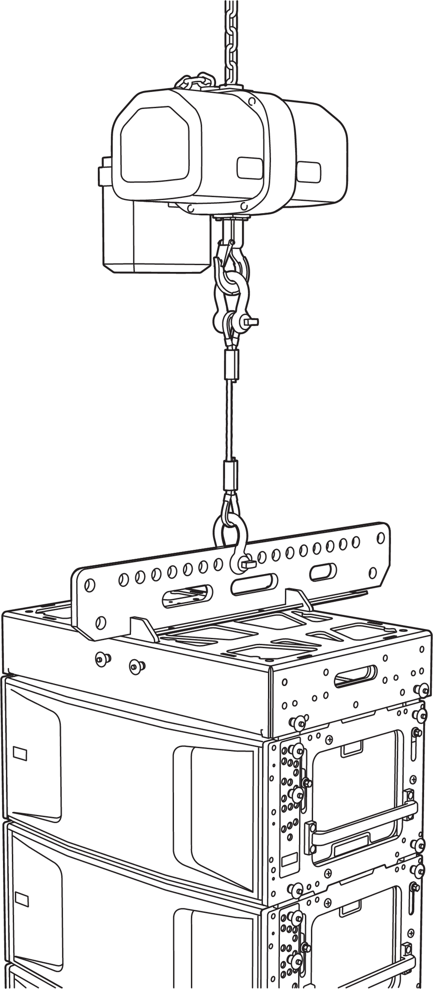
MG-PANTHER Grid Kit and PANTHER Array, Single-Point Suspension Array
To determine which of the MG-PANTHER Shackle Bar holes to connect the hoist to, model the array in MAPP. Enable the Center of Gravity function and observe where it intersects the MG-PANTHER Shackle Bar. Only when the center of gravity marker intersects the top of one of the holes is the tilt angle achievable. Note the hole number the center of gravity marker intersects. If the desired angle is not achieved, select the opposite grid orientation, forward/ rearward, or consider consulting a qualified rigger to design a bridle with an adjustable leg.
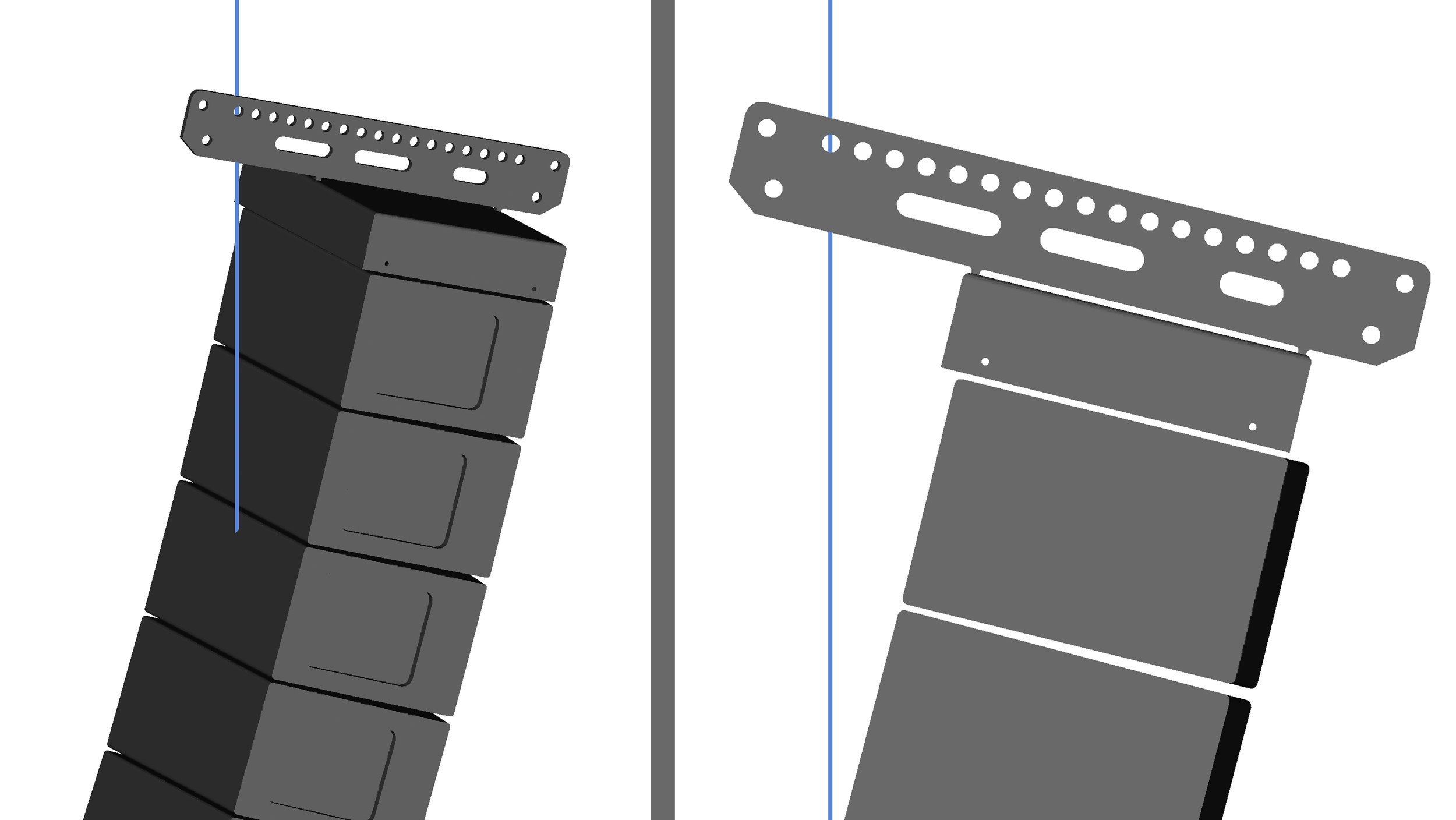
PANTHER Array in MAPP, Center of Gravity Marker Intersecting Hole 18 of the MG-PANTHER Shackle Bar
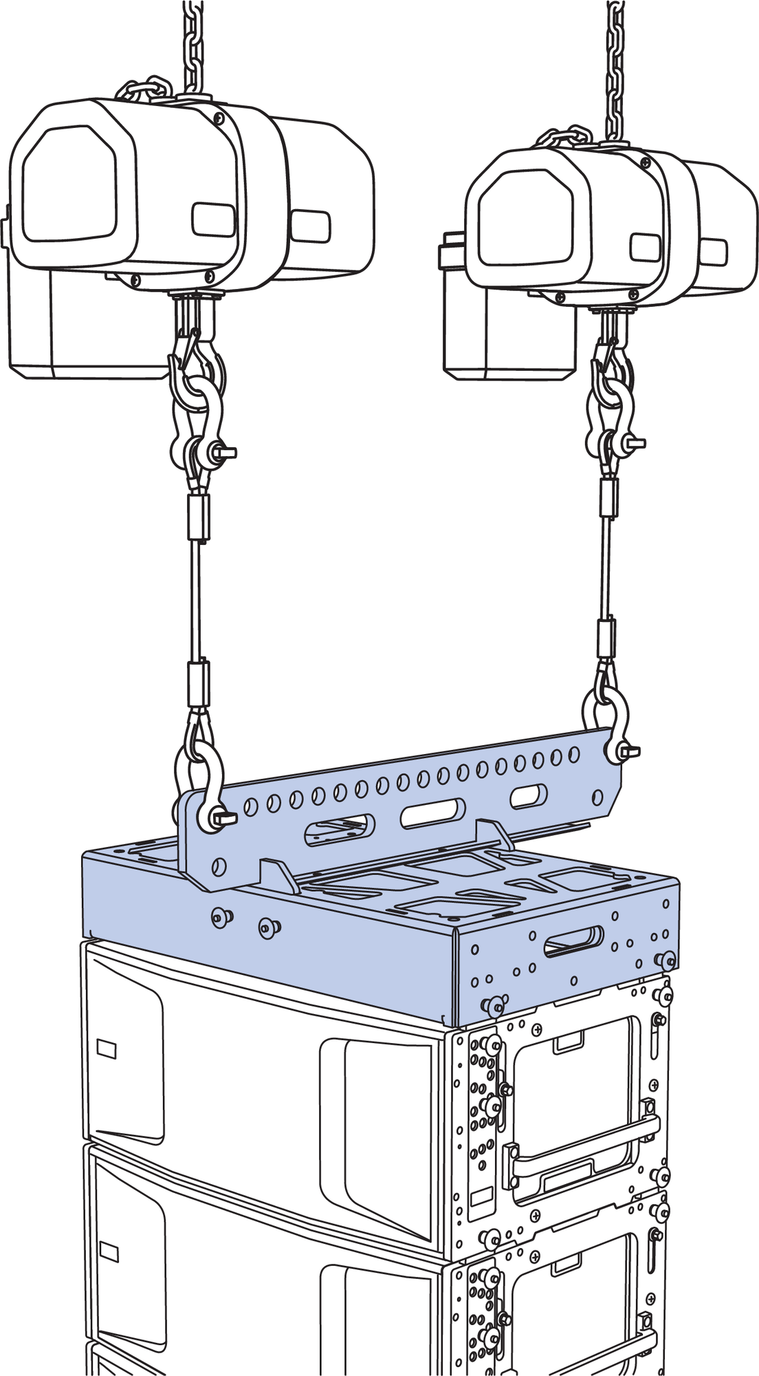
Dual-Point Rigging
When suspending an array from two points on the MG-PANTHER Shackle Bar, the uptilt or downtilt of the MG-PANTHER Grid Kit is adjusted by changing the height of the front or rear hoists.
MG-PANTHER Grid Kit and PANTHER Array, Dual-Point Suspension
The orientation of the MG-PANTHER Shackle Bar changes where the center of gravity of the array intersects the MG-PANTHER Shackle Bar. To determine which orientation to use, model the array in MAPP and choose the orientation that most evenly distributes the load between the front and rear rigging points.
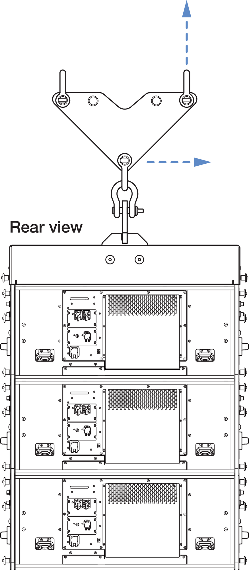
Rotate the Shackle Bar to Change Shackle Bar Orientation Relative to the PANTHER Cabinets
The MG-PANTHER Shackle Bar orientation relative to the PANTHER cabinets is referred to as “rearward” when maximum uptilt is desired, and “forward” when maximum downtilt is desired.
MG-PANTHER Shackle Bar in Rearward (Maximum Uptilt) and Forward (Maximum Downtilt) Orientations
See Assembling Arrays and Disassembling Arrays for instructions.
PANTHER GuideALinks
PANTHER loudspeakers are equipped with four captive GuideALinks providing connection to the cabinet above or to the MG-PANTHER Grid Kit. Located at the top corners of the cabinet, the GuideALinks extend into the GuideALink sockets of the cabinet above it or into the GuideALink sockets of the MG-PANTHER Grid Kit. Grasp the hexagonal-shaped knob to raise and lower GuideALinks. The GuideALink position is secured by inserting supplied quick-release pins.
Caution
Never grasp the GuideALink itself to move it. Always use the hex-shaped knob to raise and lower GuideALinks to avoid hand injury.
PANTHER GuideALinks Extended
Caution
Ensure the quick-release pins are fully inserted and locked during array assembly.
The pins are secured to the PANTHER loudspeakers with lanyards. For all pin locations, only use pins whose lanyards are attached to the same cabinet when securing GuideALinks. If a pin with a lanyard attached to one cabinet is used in an adjacent cabinet, the lanyard attachment may be damaged as the array is lifted and the splay angles open.
PANTHER GuideALinks must be secured with the included quick-release pins. At no time should the weight of the loudspeaker rest on the GuideALink knobs when the links are fully extended (without the pins inserted). GuideALink knobs are only used to extend and retract the links.
Rear GuideALinks
The rear GuideALinks are the rotation point between linked PANTHER loudspeakers when splayed. The splay angle between cabinets is determined by the front GuideALinks.
PANTHER Rear GuideALink Extended and Pinned.
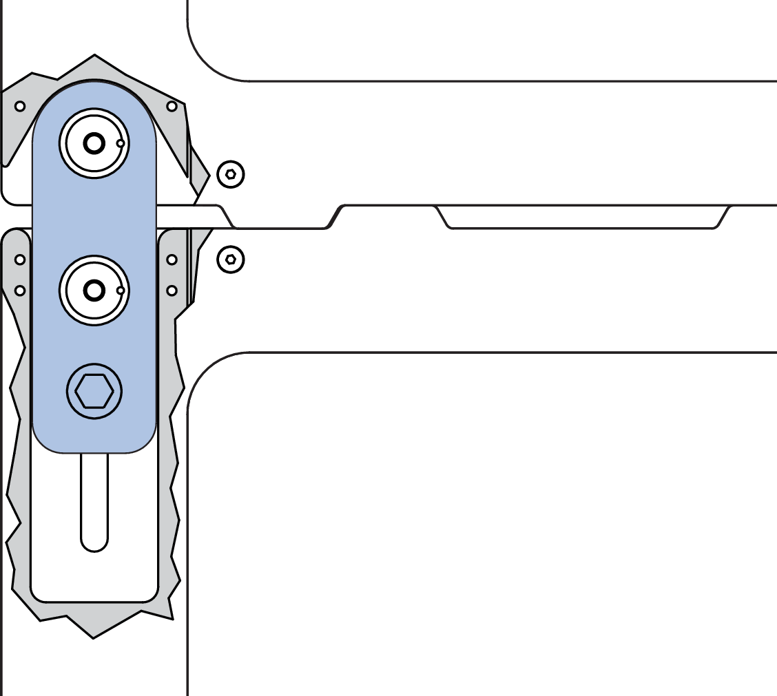
Front GuideALinks
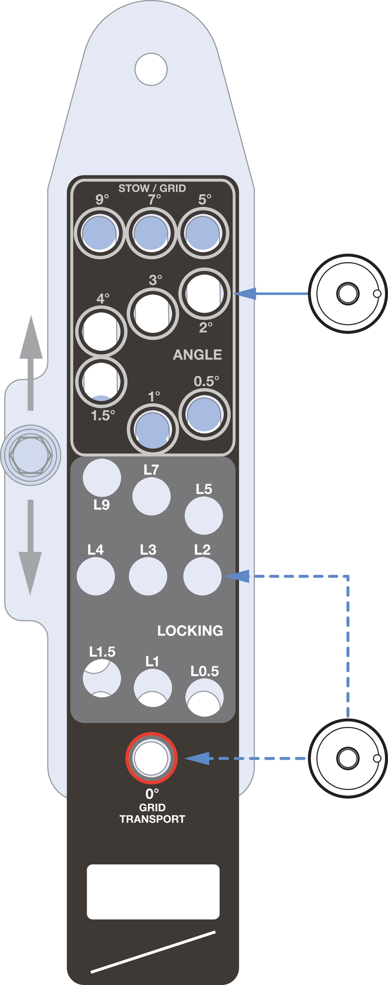
The front GuideALinks determine the splay angle of the cabinet relative to the cabinet above it. The splay angle is set by inserting one of the included quick-release pins on each side of the cabinet in one of the gray-on-black ANGLE holes. For example, when the front GuideALinks are pinned in place at 5 degrees, the downtilt of the cabinet is 5 degrees more than the downtilt of the cabinet above it.
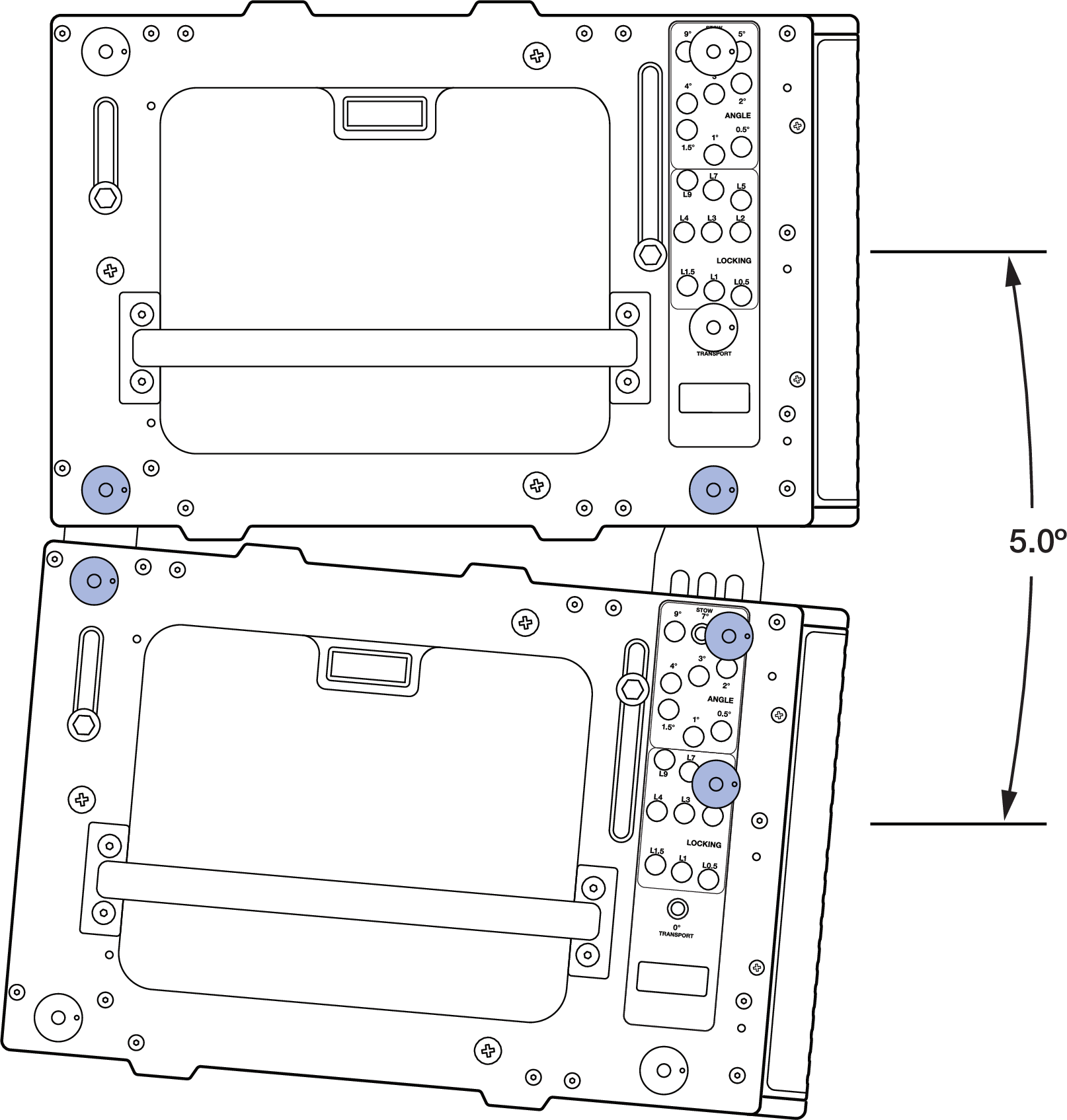
PANTHER GuideALinks Connected at 5 Degrees
The front GuideALinks of the cabinets include 9 ANGLE and 9 LOCK holes. These holes allow quick-release pins to be inserted in one of the ANGLE holes while the cabinets are stacked on caster frames. When the cabinets are lifted, the GuideALinks extend to the desired splay angle and are locked in place by inserting a quick-release pin in the corresponding LOCK hole.
A separate hole labeled 0° GRID / TRANSPORT is used when connecting the top PANTHER of an array to the MG-PANTHER Grid Kit or when transporting PANTHER cabinets.
PANTHER Front GuideALink, Hex-Knob
Note
The holes in the GuideALinks are slightly larger than the quick-release pins, which is necessary for array assembly. Due to this small dimensional difference, if multiple cabinets are set to 0° (zero degrees) and the array is tipped down when suspended, the resulting splay angles may be slightly negative rather than positive. The accumulation of the small diameter differences between the GuideALink holes and the quick-release pins can cause the shape of the front of the array to be concave instead of the desired convex shape. When an array is concave in the front, the acoustic output of the array is negatively impacted and should always be avoided. Do not set splay angles to zero degrees except when transporting cabinets.
To optimize the acoustical performance of a PANTHER array, use the appropriate number of loudspeakers with the appropriate splay angles to meet the coverage requirements. Meyer Sound’s MAPP System Design and Prediction software provides the capabilities to determine the optimal array configuration.
See the Assembly and Disassembly Steps for instructions.
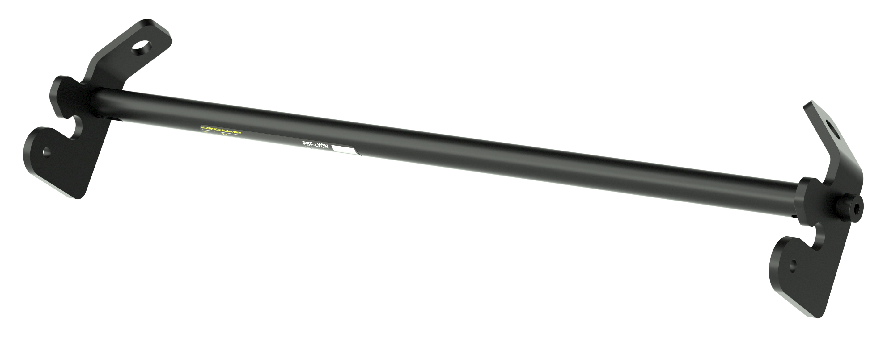
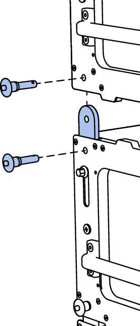
PBF-LYON
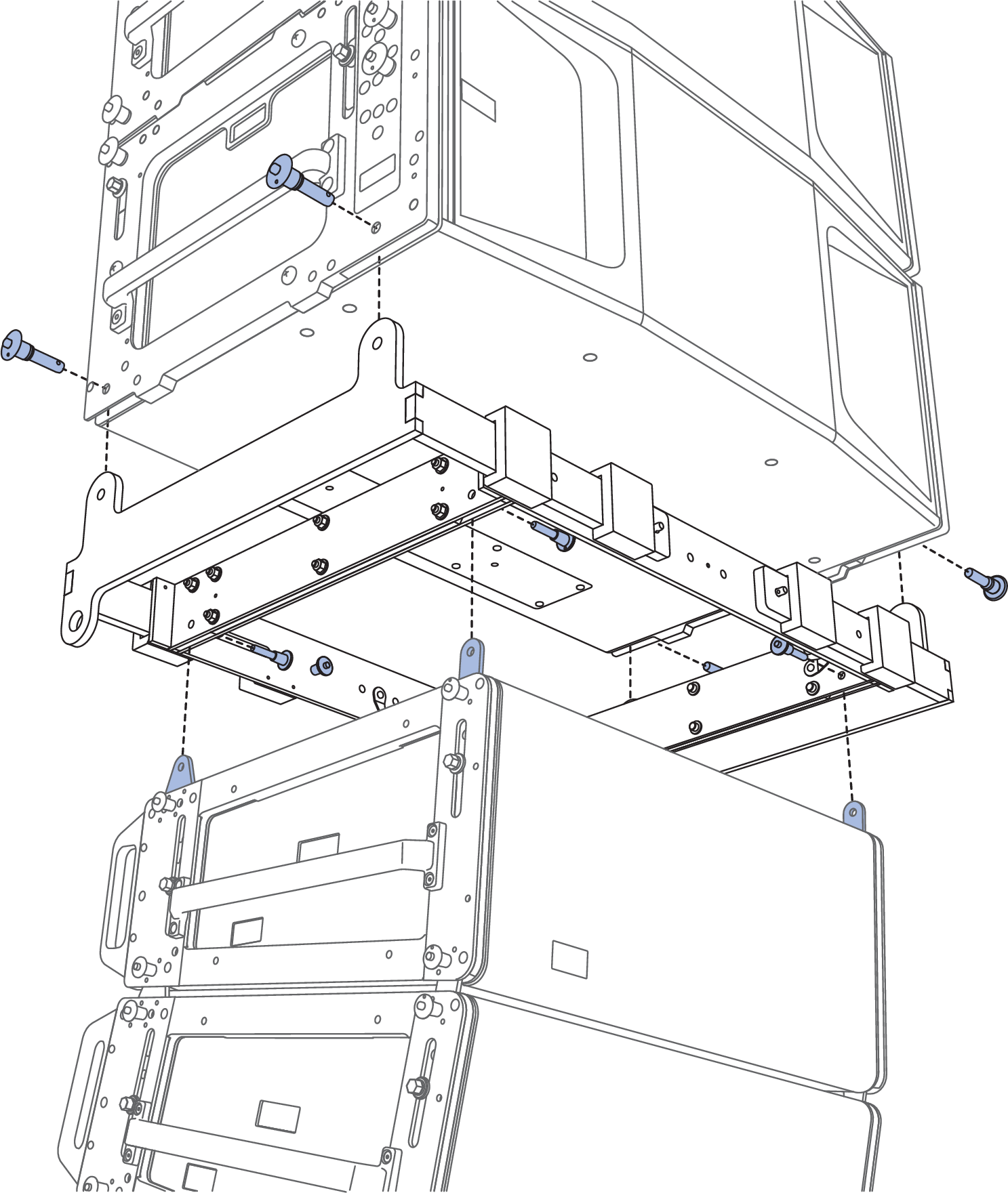
The optional PBF-LYON pull-back frame attaches to the bottom cabinet of PANTHER arrays. This accessory allows for both pull-up and pull-back configurations. The PBF-LYON Pull-Back Frame is secured to a PANTHER cabinet with two quick-release pins included with PANTHER, 7/16 x 0.90-inch QRP (black button, PN 134.065).
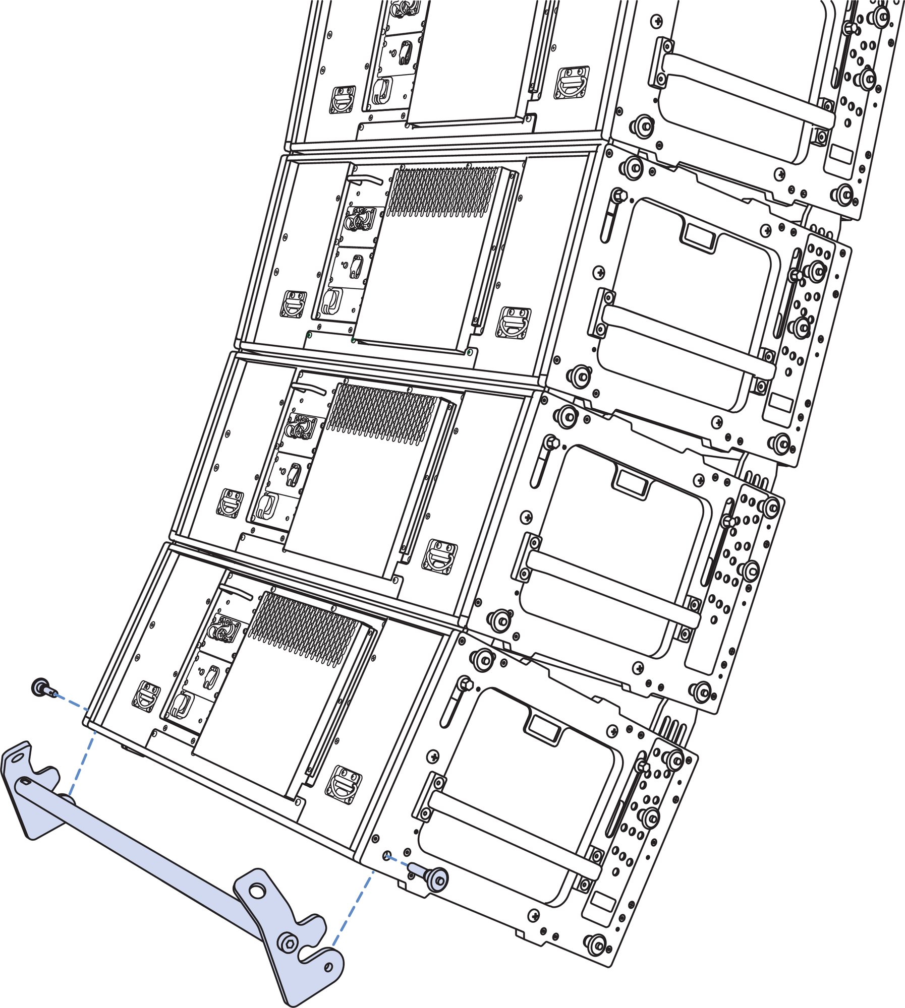
PBF-LYON Pull-Back Frame and Bottom of PANTHER Array
PBF-LYON Pull-Back Frame Kit Contents
Table 6. PBF-LYON Pull-Back Frame Kit, PN 40.232.125.01
Quantity | Part Number | Item |
|---|---|---|
1 | 45.232.125.01 | PBF-LYON Pull-Back Frame |
PBF-LYON Pull-Back Frame Dimensions
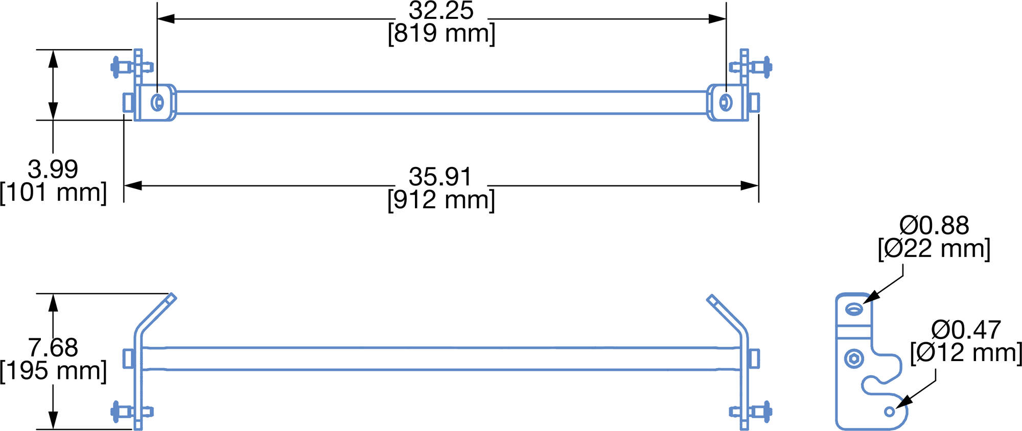
PBF-LYON Pull-Back Frame Dimensions
PBF-LYON Pull-Back Frame Load Rating
The PBF-LYON pull-back frame has the following load rating: 5:1 safety factor, 3400 lbs (1542 kg)
Caution
The rigging hardware connected to a PBF-LYON Pull-Back Frame must be sufficiently rated for the load, e.g., hoists, wire rope, shackles.
PBF-LYON Pull-Back Frame Rigging
Use rated 5/8-inch shackles to connect rated bridle hardware to the connection points at the ends of the PBF-LYON Pull-Back Frame. Use another rated 5/8-inch shackle to connect the two ends of the bridle.
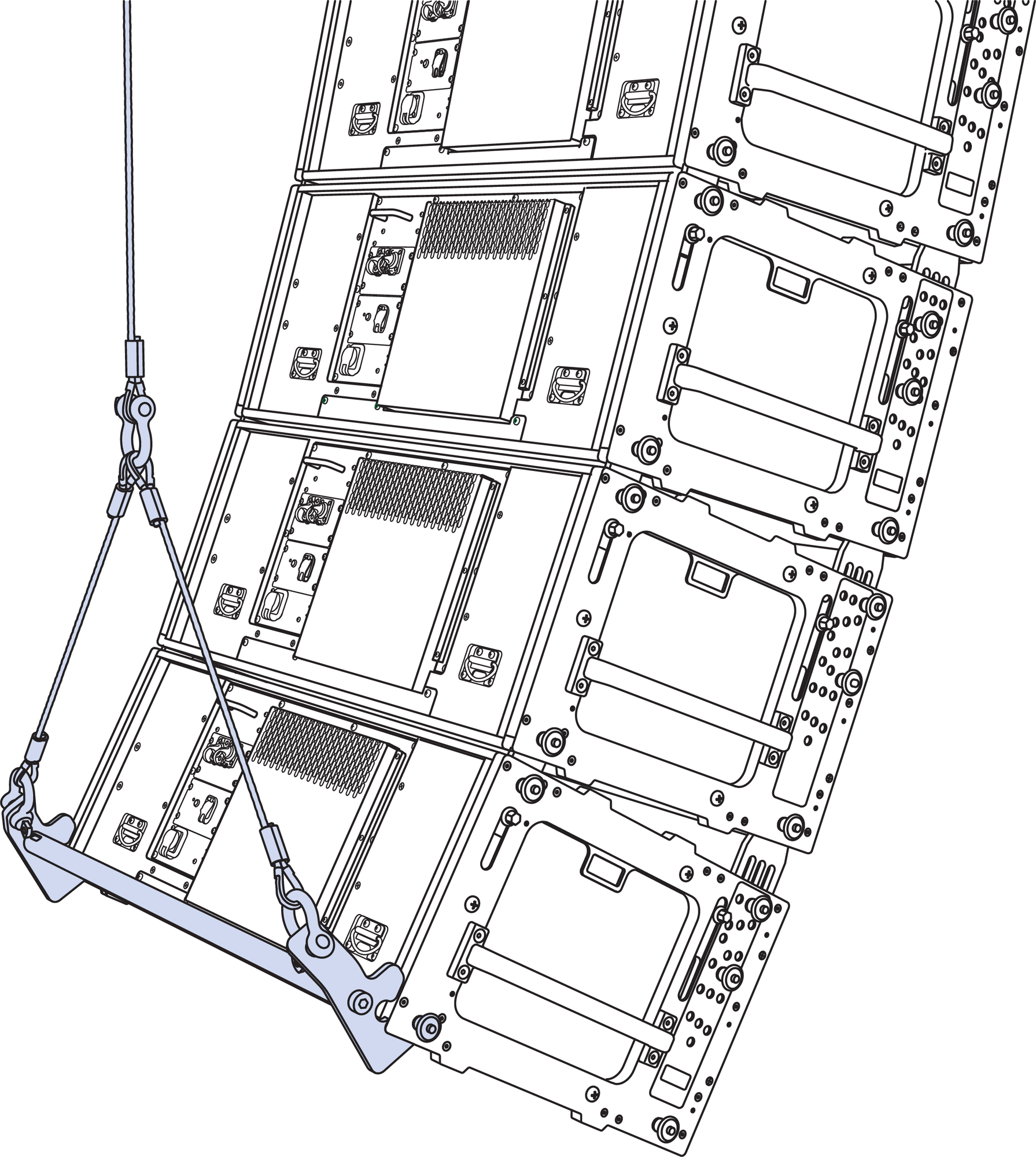
PBF-LYON Pull-Back Frame Connected to Bottom of PANTHER Array
Caution
The minimum length of the bridle legs connected to the PBF-LYON Pull-Back Frame image94.pngis 23 inches (584 mm) based on the bridle apex angle being less than 90 degrees.
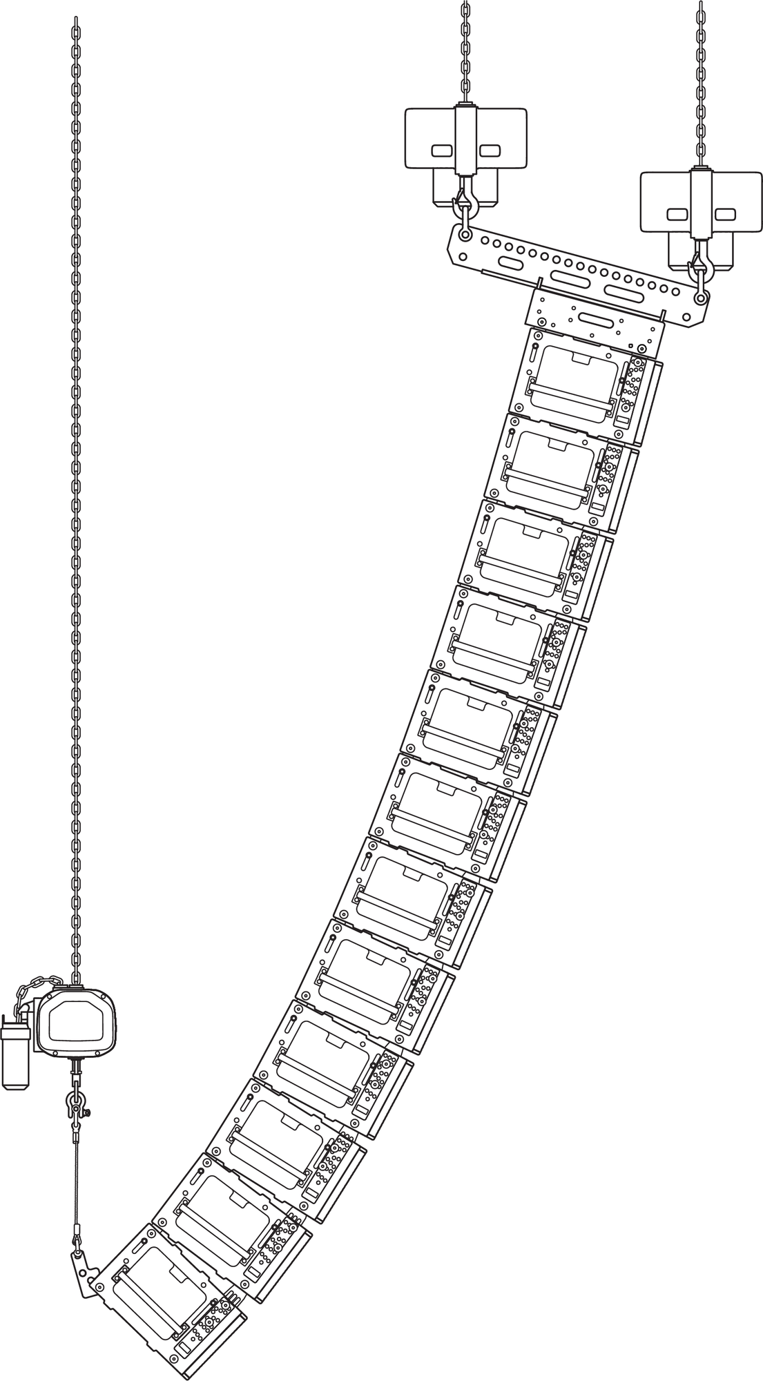
Pull-Back Configuration Overview
In the pull-back configuration, the PBF-LYON Pull-Back Frame provides additional downtilt beyond what is possible with the MG-PANTHER Grid Kit alone.
PBF-LYON, Pull-Back Configuration, Three Hoists
While designing an array in MAPP, if the desired array downtilt is not achievable, MAPP indicates this in several ways:
The Center of Gravity marker is behind the rear-most hole of the MG-PANTHER Shackle Bar
The Front Rigging Load value is negative
The Safety Limits Analysis displays, “Configuration COG is outside of Grid Pickup Points”
If the array design would benefit from additional downtilt, use the PBF-LYON in the pull-back configuration.
Caution
The pull-back configuration requires three hoists, two mounted to the MG-PANTHER Shackle Bar (holes 1 and 19), and one hoist connected to the PBF-LYON Pull-Back Frame.
When configuring arrays for pullback, the angle of the rigging hardware between the PBF-LYON Pull-Back Frame and the structural attachment point should not be more than ±10 degrees from vertical when the array is in its final position. This requires the structural attachment point of the hoist be properly located.
: When an array is suspended in the pull-back configuration, the load of the array must be shared between the pull-back hoist and the rear MG-PANTHER Shackle Bar hoist, with just enough load carried by the front MG-PANTHER Shackle Bar hoist to tension the rigging hardware. If the front hoist carries more load than the rear hoist, the array may be unstable and unintended rotation of the array could occur.
Use MAPP to determine rigging limits when an array is deployed in the pull-back configuration. The quantity of cabinets, amount of array downtilt, and rigging loads are used to calculate the safety limits
Note
The MVP Motor V Plate is not intended for use when the array is in the pull-back configuration as it provides insignificant horizontal rotation of an array in the pull-back configuration.
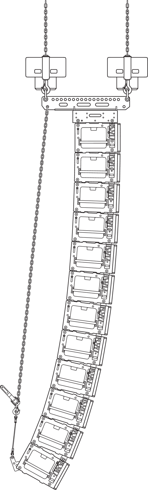
Pull-Up Configuration Overview
The pull-up configuration requires a manual hoist be connected between the PBF-LYON Pull-Back Frame and the lower utility point of the MG-PANTHER Shackle Bar. In this configuration, one or two hoists can be connected to the MG-PANTHER Shackle Bar. If desired, the MVP Motor V Plate can be connected to an array deployed in the pull-up configuration.
PBF-LYON, Pull-Up Configuration
When 12 or more PANTHER are used in an array, there are three scenarios in which the pull-up configuration is recommended:
During array assembly, if the GuideALinks do not fully extend when the array is lifted and the MG-PANTHER Grid Kit is tipped up as much as possible (upstage hoist slacked), the holes in the end frame and the GuideALink will not align, not allowing the LOCK pins to be inserted. Attempt to fully extend the front GuideALinks by pushing down on the handles on the sides of the cabinet. If this does not fully extend the front GuideALinks, configure the array for pull- up. When the manual hoist is tensioned, the front GuideALinks will fully extend allowing the LOCK pins to be easily inserted.
During array assembly, if the flown cabinets are tilted up as much as possible (upstage hoist slacked) and the rear GuideALinks of the stacked cabinets cannot be seated in the GuideALink sockets of the flown cabinet, configure the array for pull-up.
When trimmed, if the majority of the front GuideALinks of an array are in compression, the tight tolerance between the GuideALink holes and the quick-release pin diameters can accumulate, resulting in the lower cabinets of an array not achieving their desired downtilt. The pull-up configuration relieves the compression on the front GuideALinks, resulting in all the cabinets being aimed as intended.
Additional Equipment
The pull-up configuration requires a user-provided manual hoist. This hoist is connected between the bridle of the PBF-LYON and the lower utility point on the MG-PANTHER Shackle Bar. The lifting capacity of the hoist should be
less than 3400 lbs (1542 kg) to prevent overloading the PBF-LYON Pull-Back Frame. For use with all possible arrays, the minimum lifting capacity of the hoist should be at least 1500 lb (680 kg).
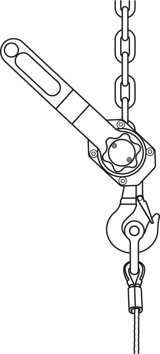
Manual Hoist Example
The Columbus McKinnon (CM) Tornado 360 Ratchet Lever Hoist is one such device. For this hoist, two accessory items available from CM are needed:
chain, length determined by the distance between the PBF-LYON and MG-PANTHER Shackle Bar utility point
chain shortening mechanism to reduce the “working” length, reduces the amount of chain taken up before load is carried
See Assembling Arrays and Disassembling Arrays, for instructions.
MTF-LYON/LEOPARD Transition Frame
With some restrictions, the optional MTF-LYON/LEOPARD transition frame suspends up to 10 LEOPARD cabinets
at a 5:1 safety factor below PANTHER arrays for downfill. The transition frame attaches to the bottom cabinet in the PANTHER array at an angle of 0 degrees and is secured with the quick-release pins included with PANTHER.
The top LEOPARD cabinet attaches to the transition frame’s inner link slots and is secured with four 5/16 x 0.875-inch quick-release pins (red button) included with the transition frame. The configuration of GuideALinks of the top LEOPARD cabinet determines the angle of its attachment, from –4.5 to +10 degrees.
The MTF-LYON/LEOPARD transition frame is collapsible for easy transport (see Collapsing the MTF-LYON/LEOPARD Transition Frame). This transition frame also includes rear pickup points for pull-back and pull-up (see Using the MTF-LYON/ LEOPARD Transition Frame for Pull-Back and Pull-Up.
PANTHER Array, MTF-LYON/LEOPARD Transition Frame, LEOPARD Array
Caution
When flying combined arrays, the total weight of the array, including any transition and pull-back hardware, should be calculated before the array is flown to verify that the weight does not exceed the load ratings.
Always use the 5/16 x 0.875-inch quick-release pins (red button) included with the MTF-LYON/LEOPARD transition frame to secure the attached LEOPARD. Do not use the 5/16 x 0.63-inch quick-release pins (black button) included with LEOPARD in the transition frame as they are shorter and will not lock in place.
Always use properly rated rigging hardware. The MTF-LYON/LEOPARD transition frame requires 1/2-inch or 5/8-inch shackles for its pickup points.
MTF-LYON/LEOPARD Transition Frame Kit Contents
Qty | Part Number | Item | |
|---|---|---|---|
 | 1 | 45.232.140.01 | MTF-LYON/LEOPARD transition frame |
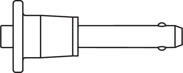 | 8 | 134.025 | 5/16 x 0.875-inch quick-release pins (red button) |
MTF-LYON/LEOPARD Transition Frame Dimensions
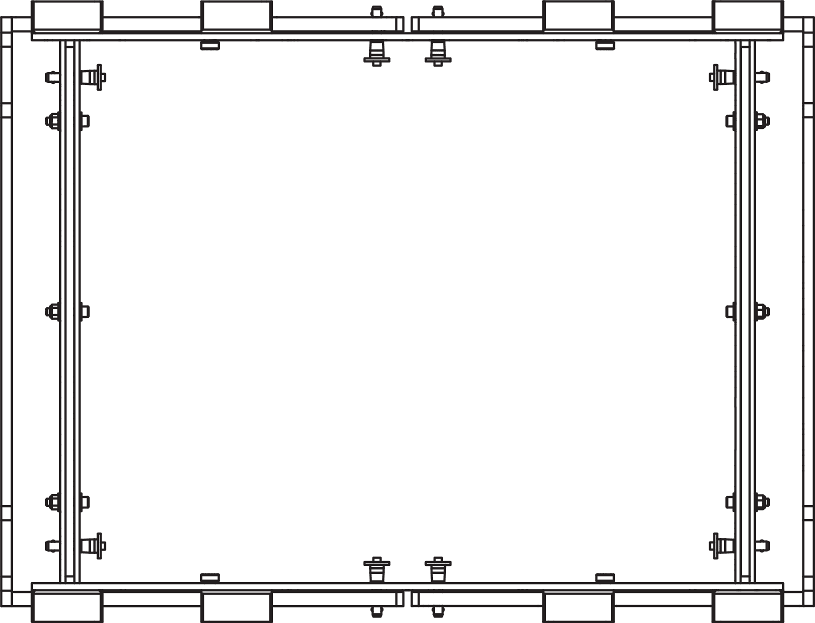
The MTF-LYON/LEOPARD transition frame collapses horizontally so it can travel installed on top of LEOPARD stacks on the MCF-LEOPARD caster frame. When the transition frame is collapsed, it occupies a smaller footprint than the MCF-LEOPARD caster frame.
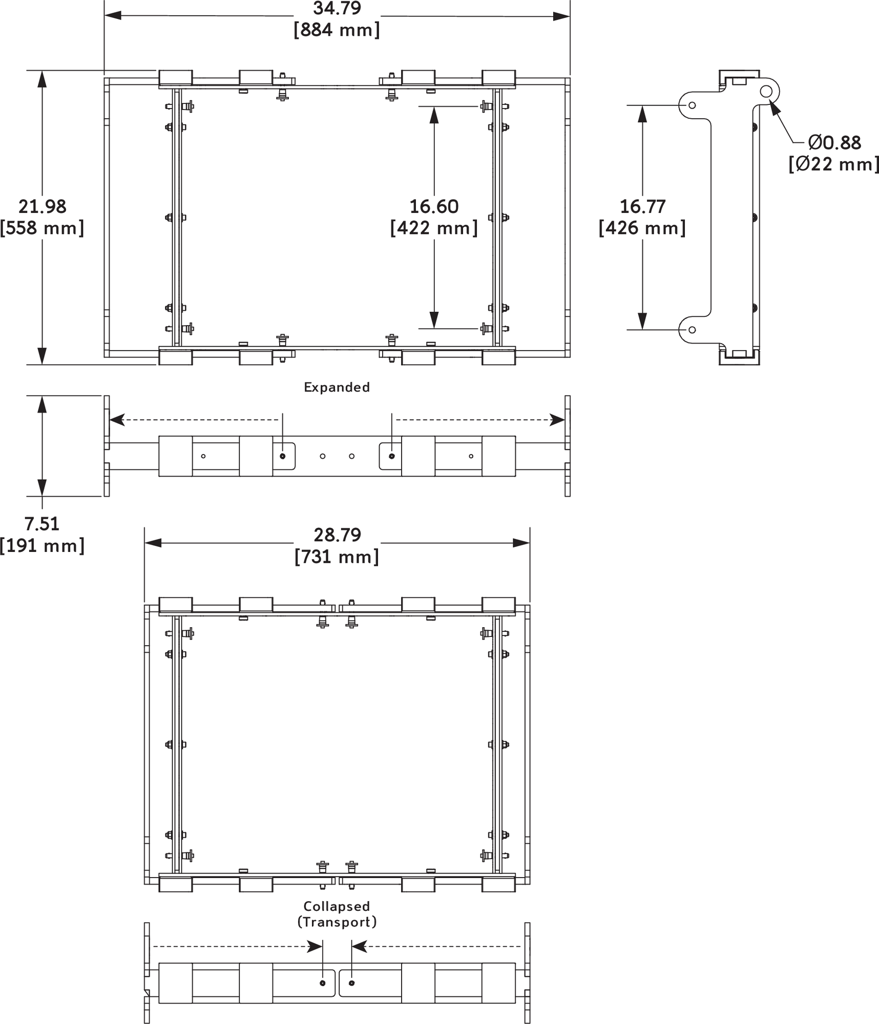
MTF-LYON/LEOPARD Transition Frame Dimensions
Collapsing the MTF-LYON/LEOPARD Transition Frame
The MTF-LYON/LEOPARD transition frame collapses horizontally so it can travel installed on top of LEOPARD stacks on the MCF-LEOPARD caster frame. When the transition frame is collapsed, it occupies a smaller footprint than the MCF-LEOPARD caster frame.
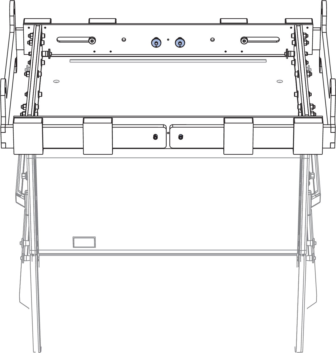
MTF-LYON/LEOPARD Transition Frame Collapsed
Before attaching the MTF-LYON/LEOPARD transition frame to a PANTHER array, expand the frame and lock it with the included 5/16 x 0.875-inch quick-release pins (red button).
MTF-LYON/LEOPARD Transition Frame, Expanded
MTF-LYON/LEOPARD Transition Frame Load Ratings (Loudspeaker)
The table below lists the maximum number of LEOPARD cabinets that can be suspended below PANTHER arrays with the MTF-LYON/LEOPARD transition frame. The configuration of the PANTHER array greatly affects the load ratings for the attached MTF-LYON/LEOPARD transition frame. In addition, the number of LEOPARD cabinets suspended below the PANTHER array greatly affects the load rating of the MTG-PANTHER Grid Kit.
Number of Flown PANTHERs | Maximum Flown LEOPARD cabinets (No Restrictions) | Maximum Flown LEOPARD cabinets (with Restrictions) |
All Splay Angles Allowed | PANTHERs in Top Half of Array with Splay Angles of 2° or Less, PANTHERs in Bottom Half of Array with Splay Angles of 5° or Less, LEOPARD cabinets with Any Splay Angle | |
5:1 Safety Factor | 5:1 Safety Factor | |
6 | 10 | 10 |
7 | 9 | 10 |
8 | 9 | 10 |
9 | 9 | 10 |
10 | 9 | 10 |
11 | 9 | 9 |
12 | 7 | 9 |
13 | 4 | 9 |
14 | 2 | 9 |
15 | 8 | |
16 | 6 | |
17 | 4 | |
18 | 2 |
Caution
Do not exceed the load ratings to avoid potential risk of personal injury and/or equipment damage. To verify pull-back load ratings, model the array in MAPP prediction software.
When flying combined arrays, the total weight of the array, including any transition and pull-back hardware, should be calculated before the array is flown to verify the weight does not exceed the load ratings.
Note
Additional array configurations for the MTF-LYON/LEOPARD transition frame are possible. Model the array in MAPP prediction software to determine whether a configuration exceeds the load ratings or not.
Using the MTF-LYON/LEOPARD Transition Frame for Pull-Back and Pull-Up
The MTF-LYON/LEOPARD transition frame includes two rear pickup points that provide pull-back for extreme array downtilts. The pickup points can also be used for pull-up to expand the PANTHER array’s splay angles during installation so the LOCK pins can be more easily inserted. The MTF-LYON/LEOPARD transition frame requires 1/2- inch or 5/8-inch shackles for its pickup points.
When the MTF-LYON/LEOPARD transition frame is used for pull-back, to tilt the array, the transition frame must be hoisted by a motor separate from and behind the MG-PANTHER Grid Kit. The pull-back motor must not be attached to the grid.
MTF-LYON/LEOPARD Transition Frame with Pull-Back
Caution
When configuring arrays with pull- back, when in final position, the pull-back chain should not be greater than ±10 degrees from vertical.
When the MTF-LYON/LEOPARD transition frame is used for pull-up, to expand the PANTHER array’s splay angles during installation so the LOCK pins can be more easily inserted, the transition frame is hoisted by a manual hoist located between the transition frame and the utility hole of the MG- PANTHER Shackle Bar.
Caution
When flying combined arrays, the total weight of the array, including any transition and pull-back hardware, should be calculated before the array is flown to verify that the weight does not exceed the load ratings.
Always use properly rated rigging hardware. The MTF-LYON/LEOPARD transition frame requires 1/2-inch or 5/8-inch shackles for its pickup points.
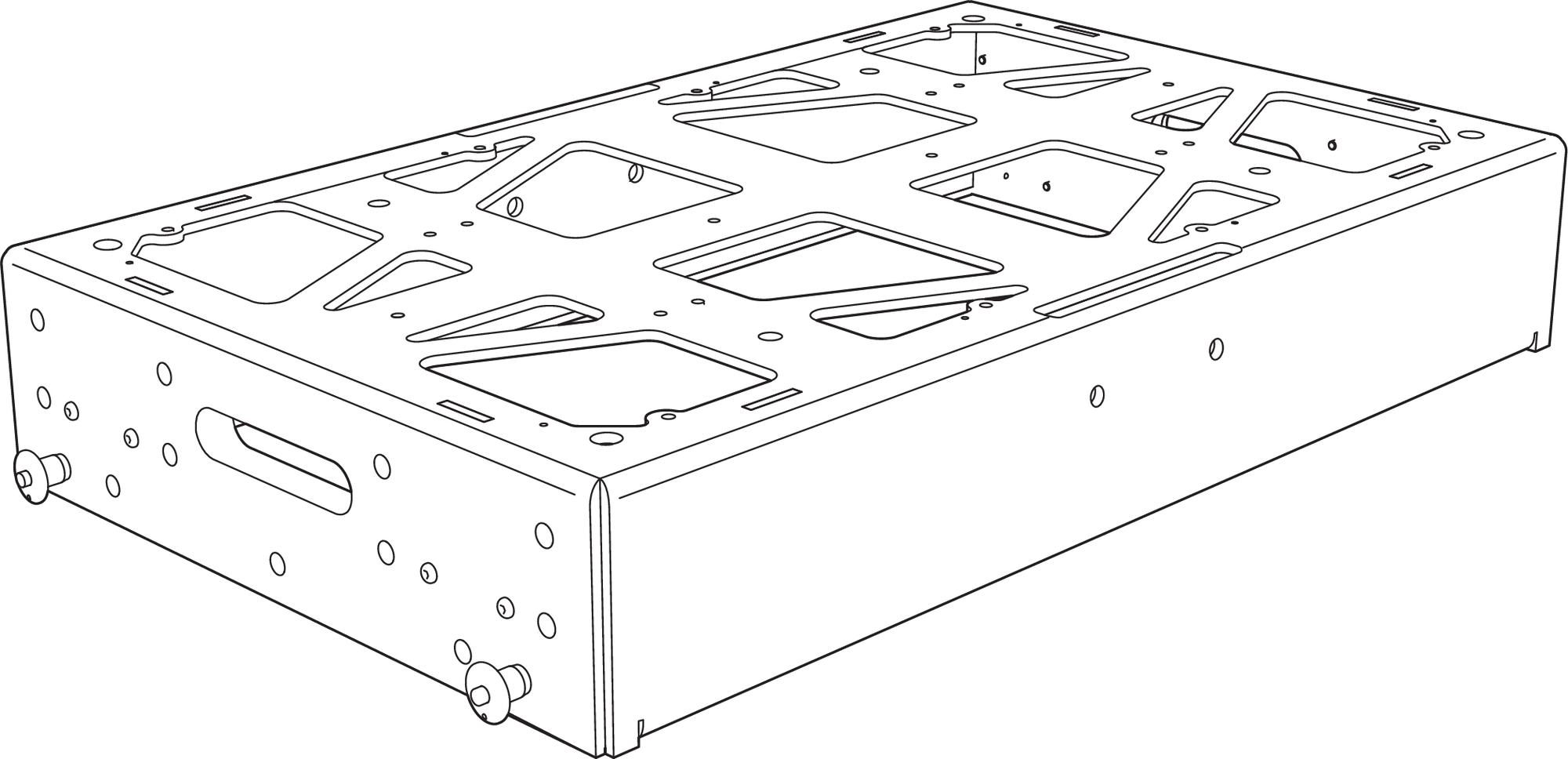
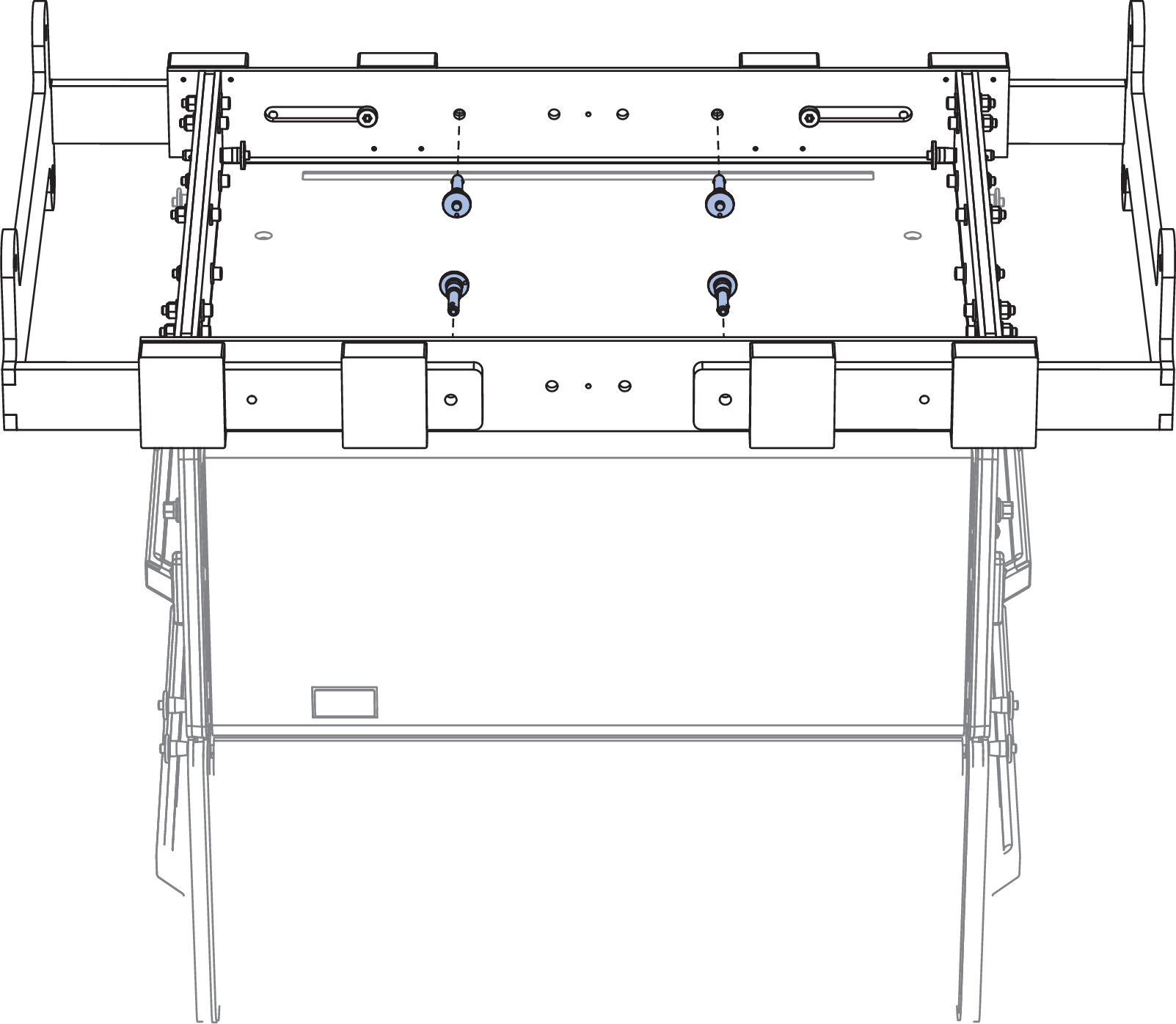
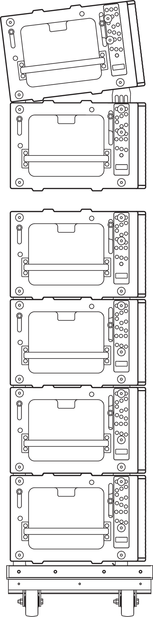
MCF-PANTHER Caster Frame
The MCF-PANTHER Caster Frame safely transports up to four PANTHER loudspeakers and an MG-PANTHER Grid Box making it easy to assemble and disassemble arrays in groups of four cabinets.
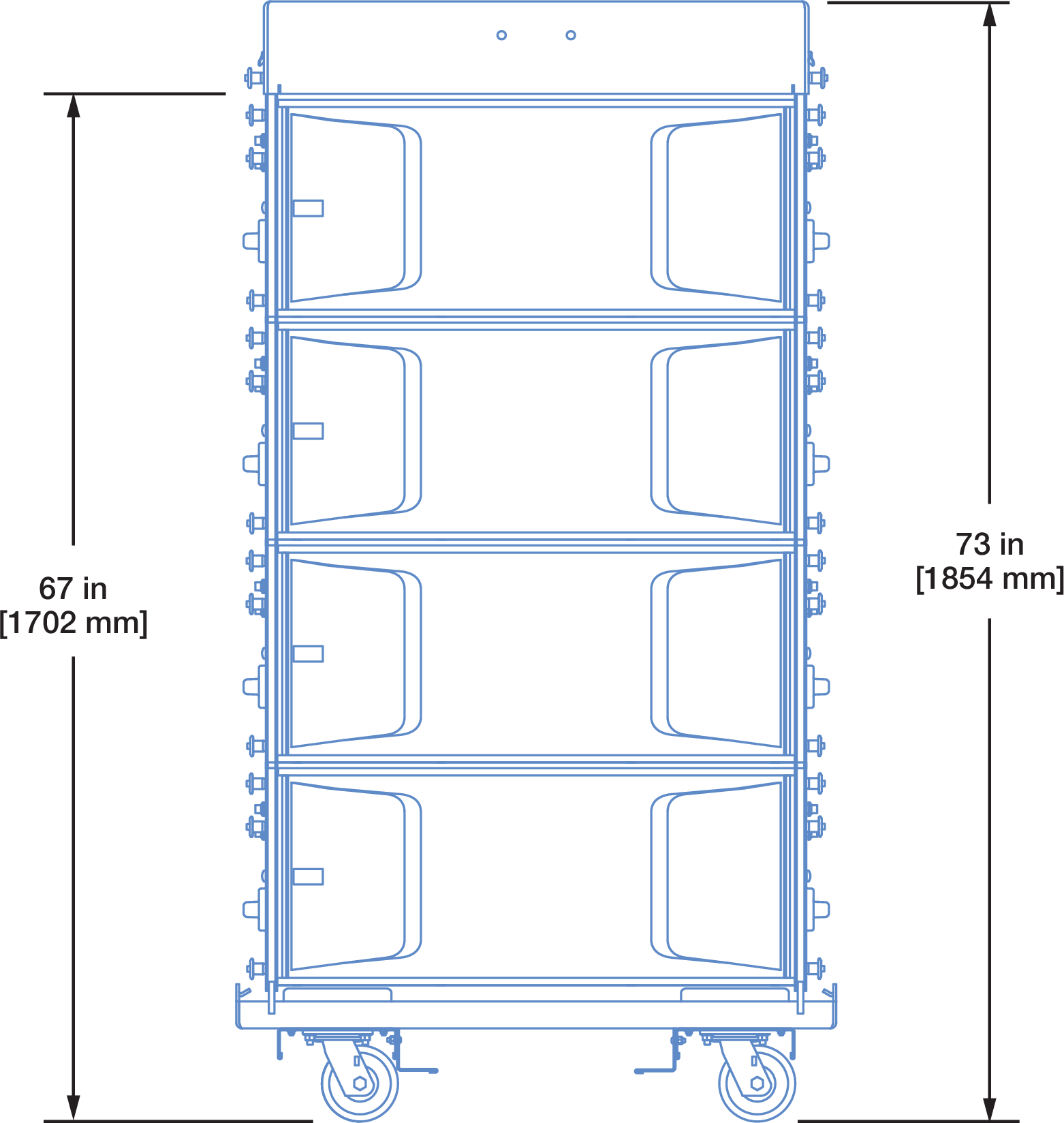
Dimensions of MG-PANTHER Grid Box, Four PANTHER Cabinets, MCF-PANTHER Caster Frame
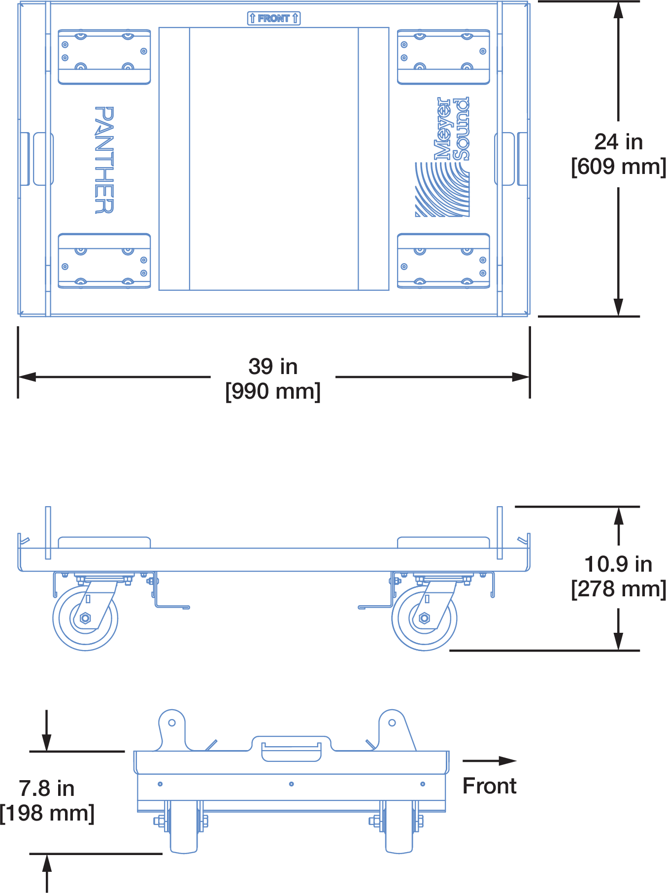
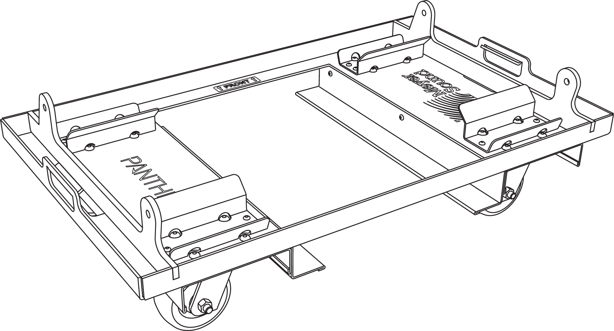
MCF-PANTHER Caster Frame Dimensions
The caster frame includes four fixed attachment points that align with the GuideALink sockets of the bottom PANTHER of an array. The caster frame is secured with the quick-release pins included with PANTHER, 7/16 x 0.90-inch QRP (black button, PN 134.065).
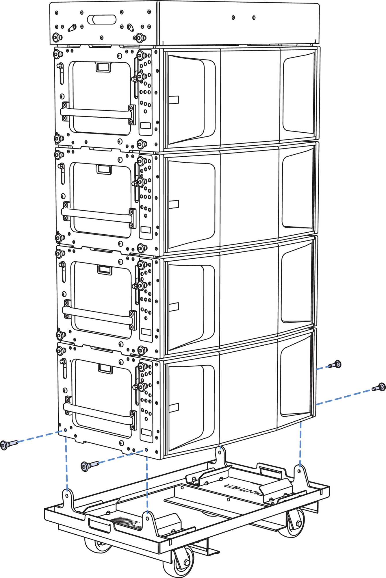
MCF-PANTHER Caster Frame with PANTHER Stack
Caution
Do not transport 4-high stacks of PANTHER with the MG-PANTHER Shackle Bar attached to the Grid Box. This exceeds the safety limits for tip-over, which may cause injury.
Tip
Durable, 4-high nylon covers are available to ensure the PANTHER cabinets are protected during transport.
The caster frame includes forklift guides between the wheels to prevent damage to them.
MCF-PANTHER Caster Frame with PANTHER Stack
If desired, the forklift guides can be removed without affecting the structural integrity. Remove the three bolts securing each of the guides.
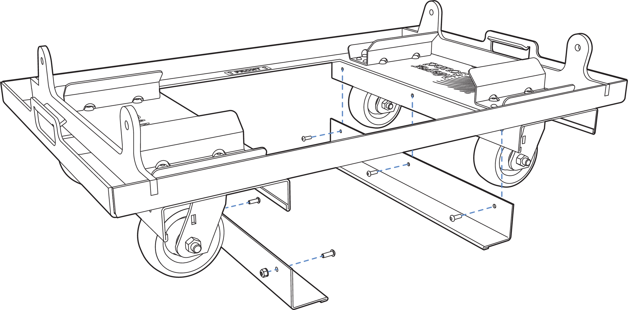
MCF-PANTHER Caster Frame, Forklift Guides Removed
Safety Guidelines for the MCF-PANTHER Caster Frame
While the MCF-PANTHER Caster Frame supports up to four cabinets plus the MG-PANTHER Grid Box, use extreme caution when moving the caster frame and cabinets to avoid tipping.
When rolling a caster frame and cabinets, slow down when the surface is uneven, e. g., cracks in concrete floors, cable ramps, transitions in floor coverings, etc.
Do not move stacks in the front-to-rear direction of the PANTHER cabinets (the long side) as the risk of injury increases. Always move stacks sideways to avoid tipping.
When moving the caster frame with PANTHER cabinets, always use the handles of the cabinets and push or pull from one of the ends.
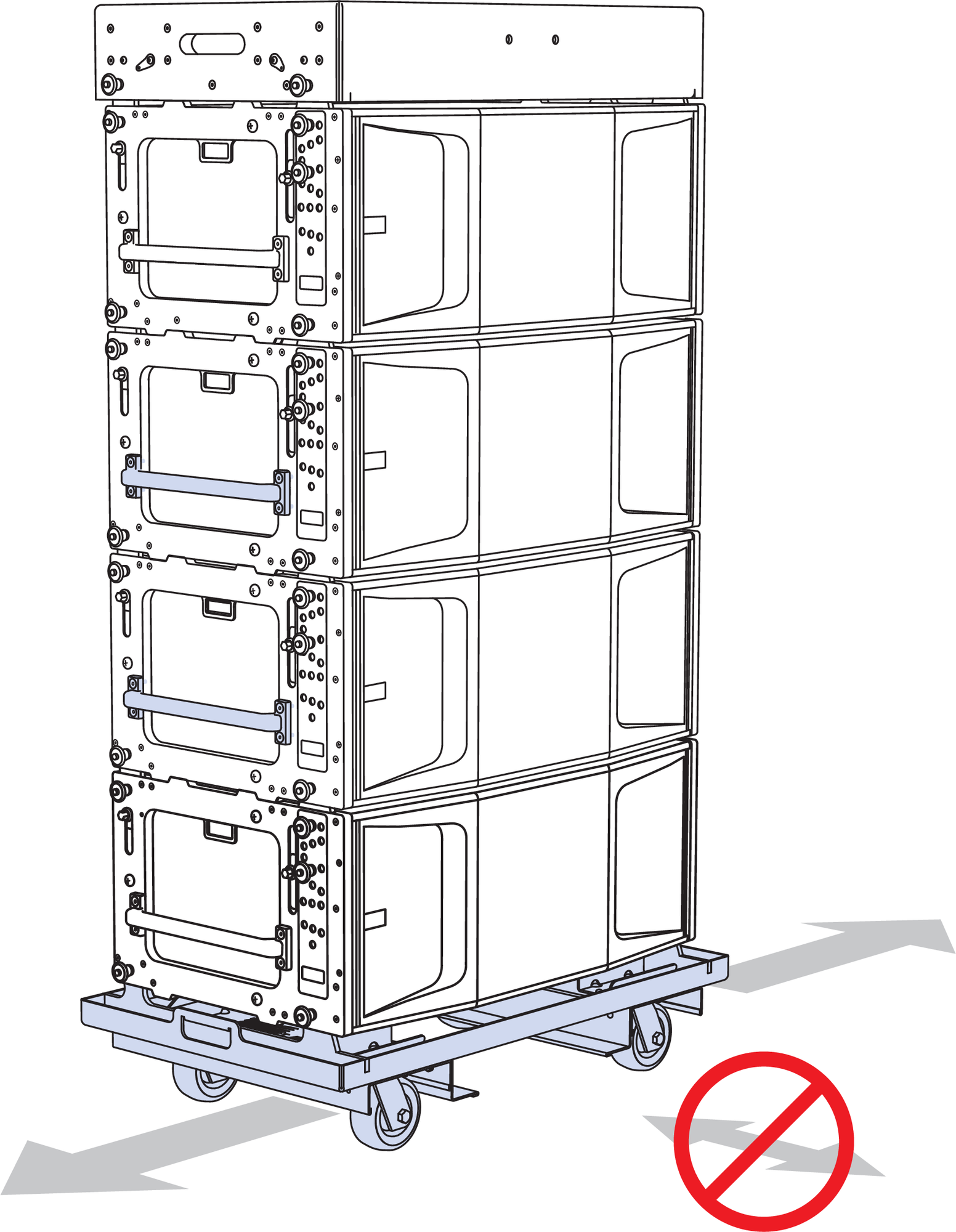
MCF-PANTHER Caster Frame with PANTHER Stack
To avoid tipping, transport stacks with all the GuideALinks connected to adjacent cabinets. The front links should be secured with pins inserted in the 0° GRID / TRANSPORT hole, below the white- on-gray LOCK holes. The pins in the gray-on-black ANGLE holes can be in any position, except when connecting to the MG-PANTHER Grid Box, insert a pin in the gray-on-black STOW / GRID 7° hole.
The caster frames must be removed before the array is flown.
Assembling Arrays
Danger
BEFORE ASSEMBLING AN ARRAY, REVIEW THE Safety Statement for Rigging.
User-Provided Equipment
Depending on the application and the needs, the following equipment may be needed or considered:
Hoists, Motorized
Hoists, Manual – used for Pull-Up Configuration
Rated Rigging Hardware, e. g., shackles, wire rope, pear rings, etc.
Inclinometer
Tape Measure
Laser Distance Measurement Device
Load Cells – used to measure rigging loads
Note
When using inverted chain motors (motor down), a short length of wire rope or deck chain added between the MG-PANTHER Grid Kit and the hook on the motor allows proper collection of the take-up chain in the chain bag. These extensions also prevent the chain bag of the front motor from hanging in front of the top cabinet, obstructing the high-frequency output.
Chain Motors with Wire Rope Elevating Motors Above MG-PANTHER Grid Kit.
Additional Requirements for MG-PANTHER Grid Kit Load Ratings
Caution
If a bridle is used between MG-PANTHER Shackle bar points, the angle at the apex of the bridle legs must not be greater than 90 degrees.
The weight of any additional items suspended with the array, e. g., downfill loudspeakers, pull-back accessories, transition accessories, and cable, must be considered when calculating the weight being suspended.
Rigging Hardware Minimum Rating
Caution
When an array is suspended using two hoists, it is very likely during the assembly of an array that the entire weight of the array will be supported by only one hoist. Always use rigging hardware rated for the maximum load it may support, e. g., hoists, wire rope, shackles, etc.
Array Assembly Preparation
Use acoustic predictions provided by Meyer Sound’s MAPP System Design and Prediction software to determine the optimum array position, number of PANTHER loudspeakers required, which PANTHER models provide the coverage desired, the MG-PANTHER Shackle Bar orientation, the Grid Kit height and angle, and the splay angles between cabinets.
From the MAPP design, document the following array information:
Trim height
Grid rotation angle
MG-PANTHER Shackle Bar orientation (forward/max downtilt or rearward/max uptilt)
If suspending from a single-point, document which attachment point of the MG-PANTHER Shackle Bar to connect the hoist to
Splay angles of PANTHER cabinets
Locations in the array of PANTHER models
Front and rear rigging weights
Total array weight
Drive lines, Galileo GALAXY output channels
Note
In some regions, regulations require dead hanging of all suspended loads, bypassing the loading of all moveable hoists. A dead hang uses a wire rope or chain to carry the suspended load, removing the entire load from the hoisting mechanism(s) used to raise and lower the array. Ensure the proper rigging equipment is available when needed.
Structural Attachment Point Locations
Install and locate the rigging points above the intended location of the array. The spacing of the rigging points described below is based on the dimensions of the hardware. There are several possible configurations:
MG-PANTHER Grid Kit Only
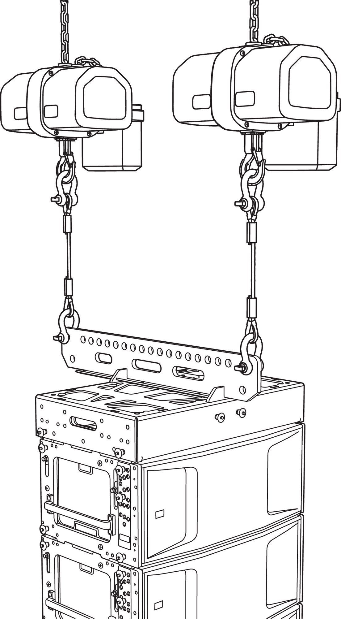
Dual-Point Suspension: Hoists, MG-PANTHER Grid Kit, PANTHER Cabinets
Two-Points: Locate the MG-PANTHER attachment points defined in the MAPP design (array Reference Point Position) in the venue. From the array Reference Point in MAPP, locate the second point 40 in (1 m) away from the first point.
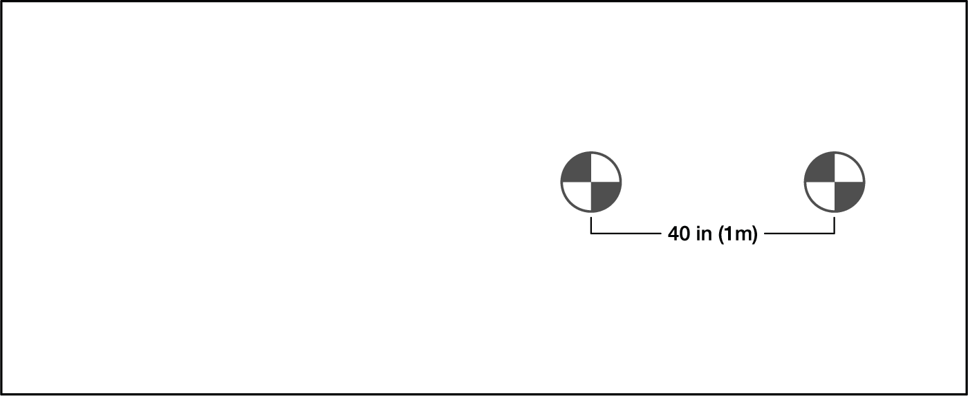
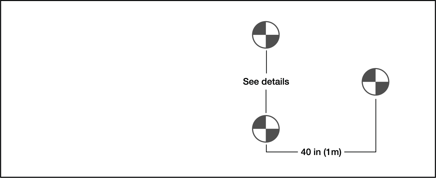
MG-PANTHER Grid Kit Hoist Locations
Single-Point: Refer to the MAPP design to determine the location of the structural attachment point by enabling the center of gravity marker that extends above the array.
If the center of gravity of the array does not align with a hole on the MG-PANTHER Shackle Bar and the grid angle is critical for the application, a bridle with an adjustable length leg connected to two holes of the MG-PANTHER Shackle Bar and the hoist provides fine adjustment of the grid angle.
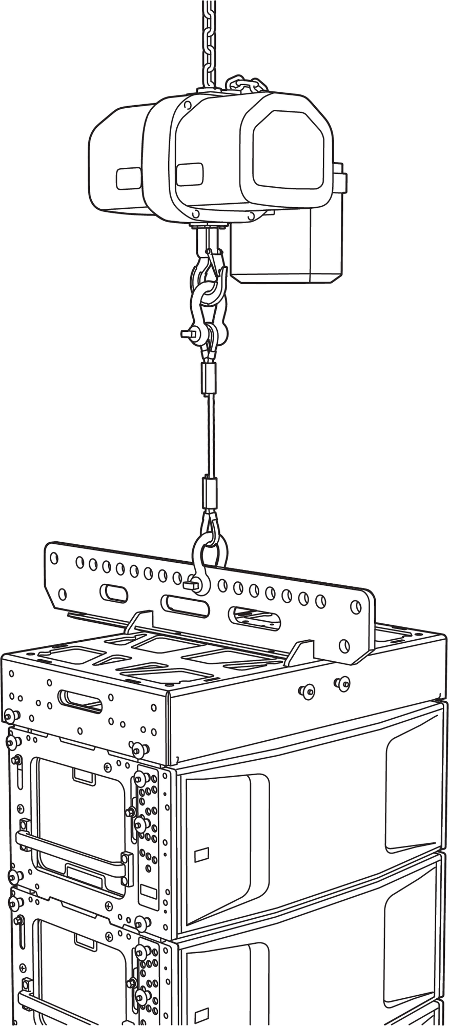
Single-Point Suspension: Hoists, MG-PANTHER Grid Kit, PANTHER Cabinets
MG-PANTHER Grid Kit and MVP Motor V Plate
Three structural attachment points are needed. Two of the points are used for hoists connected to the top of the MVP Motor V Plate (outermost holes). The third structural attachment point connects a hoist to the MG-PANTHER Shackle Bar (point 1 or 19). The bottom of the MVP Motor V Plate connects to the opposite end of the MG-PANTHER Shackle Bar (point 1 or 19).
MVP Motor V Plate Configuration: Hoists, MVP-Motor V Plate, MG-PANTHER Grid Kit, PANTHER Cabinets
The rigging points for the MVP Motor V Plate can be up to 30 in (75 cm) apart to allow more space between the hoists, provided there is at least 8 ft (2.5 m) between the top of the MVP Motor V Plate and the structural attachment points. If the distance between the top of the MVP Motor V Plate and the structural attachment points is less than 8 ft (2.5m), the distance between the two rigging points is limited to 20 in (50 cm) apart.
The third point is located 40 in (1 m) from the points used for the MVP Motor V Plate.
Grid Kit Hoist Locations for MG-PANTHER and MVP Motor V Plat
MG-PANTHER Grid Kit, Pull-Up Configuration
Pull-Up Configuration: Hoists, MG-PANTHER Grid Kit, PANTHER Cabinets, PBF-LYON, Manual Hoist
One or two structural attachment points are used to connect hoists to the MG-PANTHER Shackle Bar. The PBF-LYON is connected to the bottom cabinet of the array. A manual hoist connects the bridle of the PBF-LYON to the lower utility point of the MG-PANTHER Shackle Bar.
Hoist Locations, Two Hoists 40-inches Apart
Note
The MVP Motor V Plate can be used in conjunction with the pull-up configuration.
MG-PANTHER Grid Kit, Pull-Back Configuration
Pull-Back Configuration: Three Hoists, MG-PANTHER Grid Kit, PANTHER Cabinets, PBF-LYON
Caution
When trimmed, the maximum angle between the bottom of the array and the structural attachment point is +/- 10 degrees from vertical.
Note
The MVP Motor V Plate is not intended for use when the array is in the pull-back configuration as it provides insignificant horizontal rotation of an array in the pull-back configuration.
Three structural attachment points are used. Two points connect hoists to the MG-PANTHER Shackle Bar at points 1 and 19. The third point is located directly behind the first two points and directly above the bottom of the array when it is trimmed. This point connects a hoist to the bridle of the PBF-LYON. The distance between the MG-PANTHER Shackle Bar points and the rigging point for the hoist connected to the PBF-LYON is determined in MAPP.
Hoist Locations, Two Hoists 40-inches Apart
Array Assembly Steps
Because the PANTHER cabinets are horizontally symmetrical, when the steps below give instructions related to one side of a cabinet, always duplicate the action on the other side of the cabinet. The duplicate instruction for the other side of the cabinet is not included.
These instructions assume the PANTHER cabinets are already stacked on caster frames, ready for temporary installation, e. g., touring or one-off events, and that the MG-PANTHER Grid Box is not already connected to the top
PANTHER cabinet. For installations, it is likely that individual cabinets will be located on the working surfaces below the rigging points and added one at a time to the array. If there are questions, please contact Technical Support by visiting meyersound.com/contact.
Ready the hoisting mechanism(s).
Caution
Discover and follow all safety regulations and operational rules regarding movement of suspended loads for the region, location, and venue where the system will be deployed.
Securely mount any accessories to the MG-PANTHER Grid Kit, e. g., lasers, inclinometers, tape measure, etc.
Prepare PANTHER cabinets.
Remove protective covers from stacks of PANTHER cabinets and arrange the stacks in the order they will be added to the array.
For each PANTHER cabinet, except the top cabinet of the array:
Move a quick-release pin to the gray-on-black ANGLE hole that matches the MAPP design.
Remove the quick-release pin from the white-on- gray LOCK hole or the 0° GRID / TRANSPORT hole, allowing the pin to hang by its lanyard.
For the top cabinet of the array:
Insert a quick-release pin in the gray-on-black ANGLE hole labeled STOW / GRID 7° when connecting this cabinet to the grid.
Within the stacked cabinets, make sure all the rear GuideALinks are extended and pinned in place, connecting adjacent cabinets.
Note
The links of the top cabinet of each stack should have the GuideALinks retracted into the cabinet.
Connect the MVP Motor V Plate to hoists, if used.
Connect 3/4-inch or 7/8-inch shackles to all three MVP Motor V Plate connection points.
Connect the hoists to the two shackles at the top of the MVP Motor V Plate.
MVP Motor V Plate, Two Hoists Connected to Top Connection Points
Connect the MG-PANTHER Shackle Bar to hoist(s).
Locate the MG-PANTHER Shackle Bar on the floor or a cable trunk directly below the hoist(s).
Note
Confirm the MG-PANTHER Shackle Bar orientation (forward/rearward) matches the MAPP design orientation.
Connect 3/4-inch or 7/8-inch shackles to the MG- PANTHER Shackle Bar.
When using two hoists, connect shackles to holes 1 and 19 of the MG-PANTHER Shackle Bar.
When using a single hoist, ensure the shackle is connected to the point on the MG-PANTHER Shackle Bar defined in the MAPP design.
When the MVP Motor V Plate is added, connect the shackle at the bottom of the MVP Motor V Plate to a second 3/4-inch or 7/8-inch shackle connected to one end (hole 1 or 19) of the MG-PANTHER Shackle Bar.
Raise the hoists until the Shackle Bar is above the height of the Grid Box, whether on the floor, cable trunk, or on a stack of cabinets.
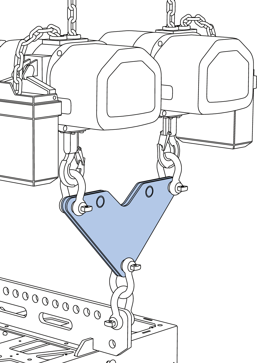
Connect the MG-PANTHER Shackle Bar to the MG-PANTHER Grid Box
Locate the Grid Box under the suspended Shackle Bar.
Lower the Shackle Bar, aligning the mounting tabs of the Shackle Bar with the slots in the Grid Box, until the Shackle Bar rests on the Grid Box.
Use the four 1/2 x 1.50-inch QRP (red button, PN 134.045) pins to secure the Shackle Bar to the Grid Box.
Caution
Make sure the quick-release pins are fully inserted and locked, unable to be removed without depressing the button of the quick- release pin.
MG-PANTHER Grid Kit, MG-PANTHER Shackle Bar, Exploded View
Connect the MG-PANTHER Grid Kit to the first stack of PANTHER cabinets.
Raise the MG-PANTHER Grid Kit until it is higher than the PANTHER cabinets being connected.
Move the first stack of PANTHER loudspeakers under the MG-PANTHER Grid Kit.
Lower the MG-PANTHER Grid Kit until it is 1 to 2 inches (2.5 cm to 5cm) above the top PANTHER cabinet, close enough to allow the front GuideALinks to extend into the GuideALink sockets of the MG-PANTHER Grid Box.
Caution
Do not attempt to “land” the MG-PANTHER Grid Kit on a PANTHER cabinet with the GuideALinks extended. Collision of the GuideALinks and the GuideALink sockets will cause excessive wear over time.
Note
For the top PANTHER cabinet, there should already be a pin in the gray-on-black ANGLE STOW / GRID 7° hole, see Step 3 above.
For the top PANTHER cabinet, grasp the hex knob of the front GuideALink and lift it until a quick-release pin can be inserted in the 0° GRID / TRANSPORT hole (below the white-on-black LOCK holes). The GuideALinks won’t be entirely seated but will guide the MG-PANTHER Grid Kit when it is lowered.
Lower the MG-PANTHER Grid Kit until its weight is supported by the front GuideALinks.
Secure the front GuideALink to the MG-PANTHER Grid Kit by inserting the 7/16 x 1.50-inch QRP (red button, PN 134.051) quick-release pin attached by lanyard to the MG-PANTHER Grid Box.
Remove the quick-release pin securing the rear GuideALink of the top PANTHER cabinet. Lift the rear GuideALink using the hex knob and replace the quick-release pin, securing the GuideALink in the raised position.
Secure the rear GuideALink of the PANTHER cabinet to the MG-PANTHER Grid Box by inserting the 7/16 x 1.50-inch QRP (red button, PN 134.051) quick-release pin attached by lanyard to the MG-PANTHER Grid Box.
Caution
Make sure the quick-release pins are fully inserted and locked, unable to be removed without depressing the button of the quick- release pin.
Secure MG-PANTHER Grid Kit to Top PANTHER Cabinet with GuideALinks
Connect the cable strain relief (cable pick) to the Utility hole at the end of the Shackle Bar.
Note
When an array is configured for pull-up with the PBF-LYON, connect a shackle with a pear ring to the utility point on the MG-PANTHER Shackle Bar. Use additional shackles connected to the pear ring to connect the cable pick and the manual hoist chain, see PBF-LYON.
Visually inspect the assembly before hoisting, make sure:
The rigging hardware is properly oriented and won’t “jam” or “foul,” especially the shackles.
Cables are properly routed and will not be strained, pinched, or damaged when the array is raised.
Each cabinet is linked to the cabinet above it, verifying that the front and rear GuideALinks are extended and pinned in place with 7/16 x 0.90-inch QRP (black button, PN 134.065) quick-release pins attached by lanyard to PANTHER cabinet.
The pins in the gray-on-black ANGLE holes match the splay angles in the MAPP design.
Remove the quick-release pins from the white-on-gray LOCK holes, leaving them hanging by their lanyards.
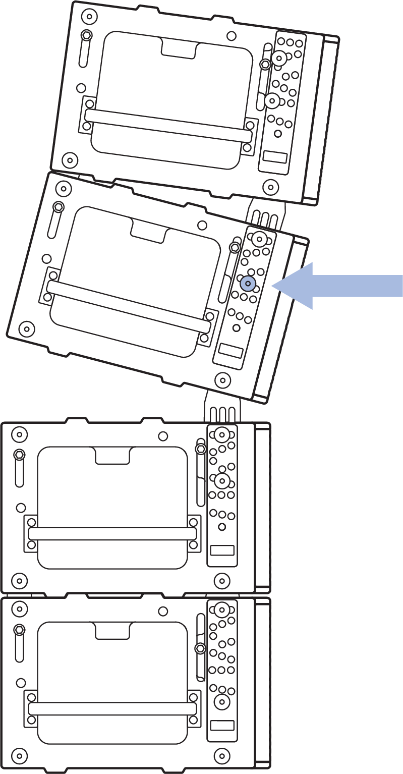
Remove the MCF-PANTHER Caster Frame
Using the hoists, lift the array until all the caster frame wheels no longer touch the working surface. The front GuideALinks will extend as the cabinets are hoisted.
Remove the MCF-PANTHER Caster Frame
Caution
Do not lift the caster frame by the handles while it is being attached to a cabinet. This creates a pinch point for hands. Only lift the caster frames by the handles when the caster frame is not connected to a cabinet.
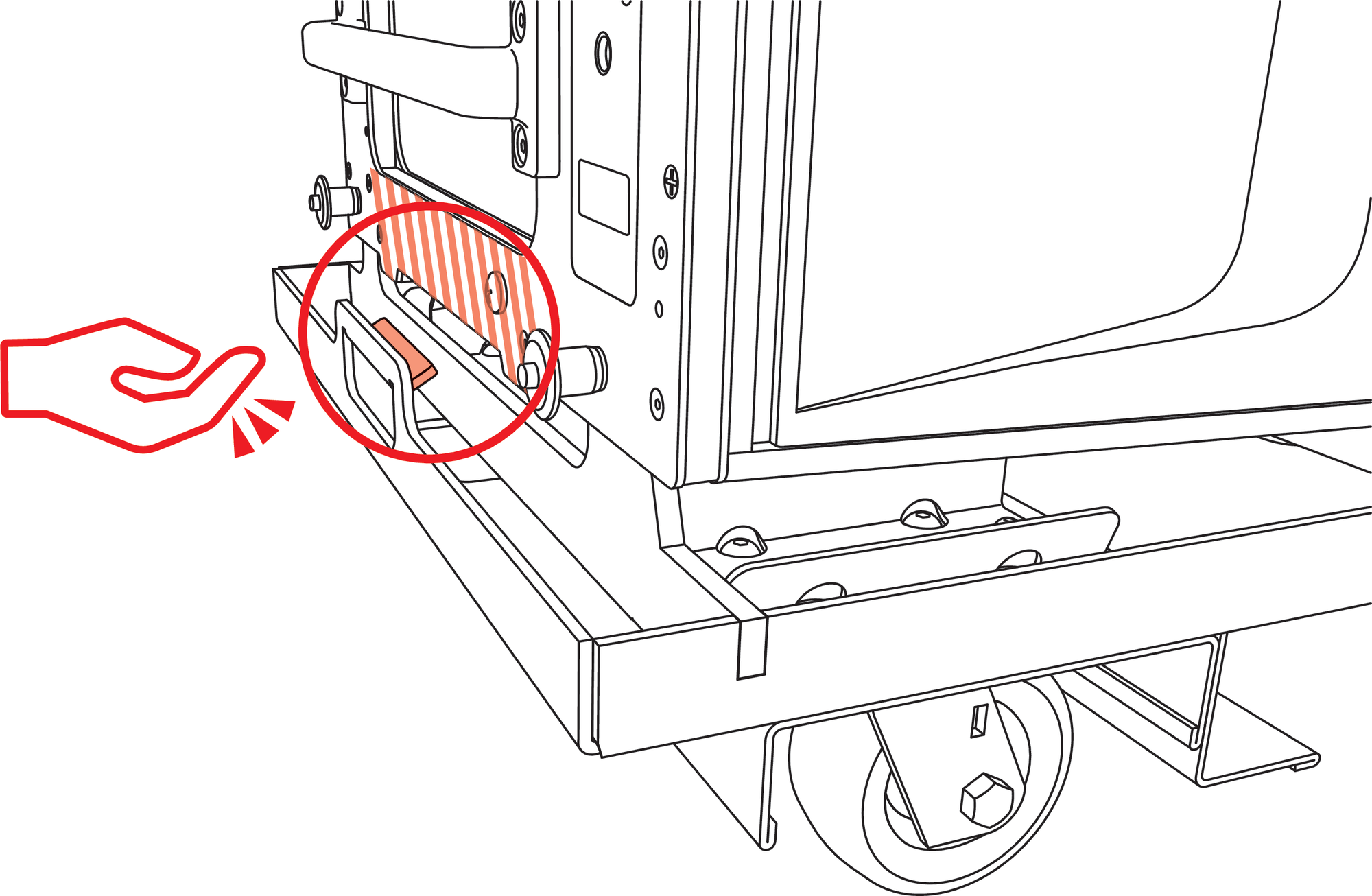
Caster Frame Handle Pinch Point
First, remove both front pins that secure the caster frame while supporting the underside of the caster frame by hand.
Lower the front wheels to the floor.
Detach Front of Caster Frame First
Next, remove both rear pins that secure the caster frame while supporting the underside of the caster frame by hand.
Lower the rear wheels of the caster frame to the floor
Replace the pins that secured the caster frame in the same holes of the PANTHER cabinet.
Caution
Always lower the front of the caster frame first. If the rear is lowered first and it is high enough off the ground, the caster frame can swing and damage the front lip of the PANTHER cabinet.
Do Not Lower the Rear of the Caster Frame First
Lock the splay angles.
For each cabinet, insert the quick-release pins hanging from lanyards in the white-on-gray LOCK holes that correspond to the gray-on-black ANGLE holes.
Caution
Make sure the quick-release pin locations for the white-on-gray LOCKING holes match those of the corresponding gray-on-black ANGLE holes, and that the locations of the quick-release pins for the left and right sides of the cabinets mirror each other.
Make sure the quick-release pins are locked and fully inserted
Tip
The LOCK hole that corresponds to an ANGLE hole is always three holes below the ANGLE hole.
Connect the power, audio signal, and network cables for each cabinet. Use the cable rings on the rear of the cabinets for strain relief.
Prepare to connect another stack of loudspeakers.
Ensure the connected cabling has enough slack to not be strained, pinched or damaged as the array is raised.
Raise the array 6 inches (15 cm) higher than the next stack of PANTHER cabinets to be attached.
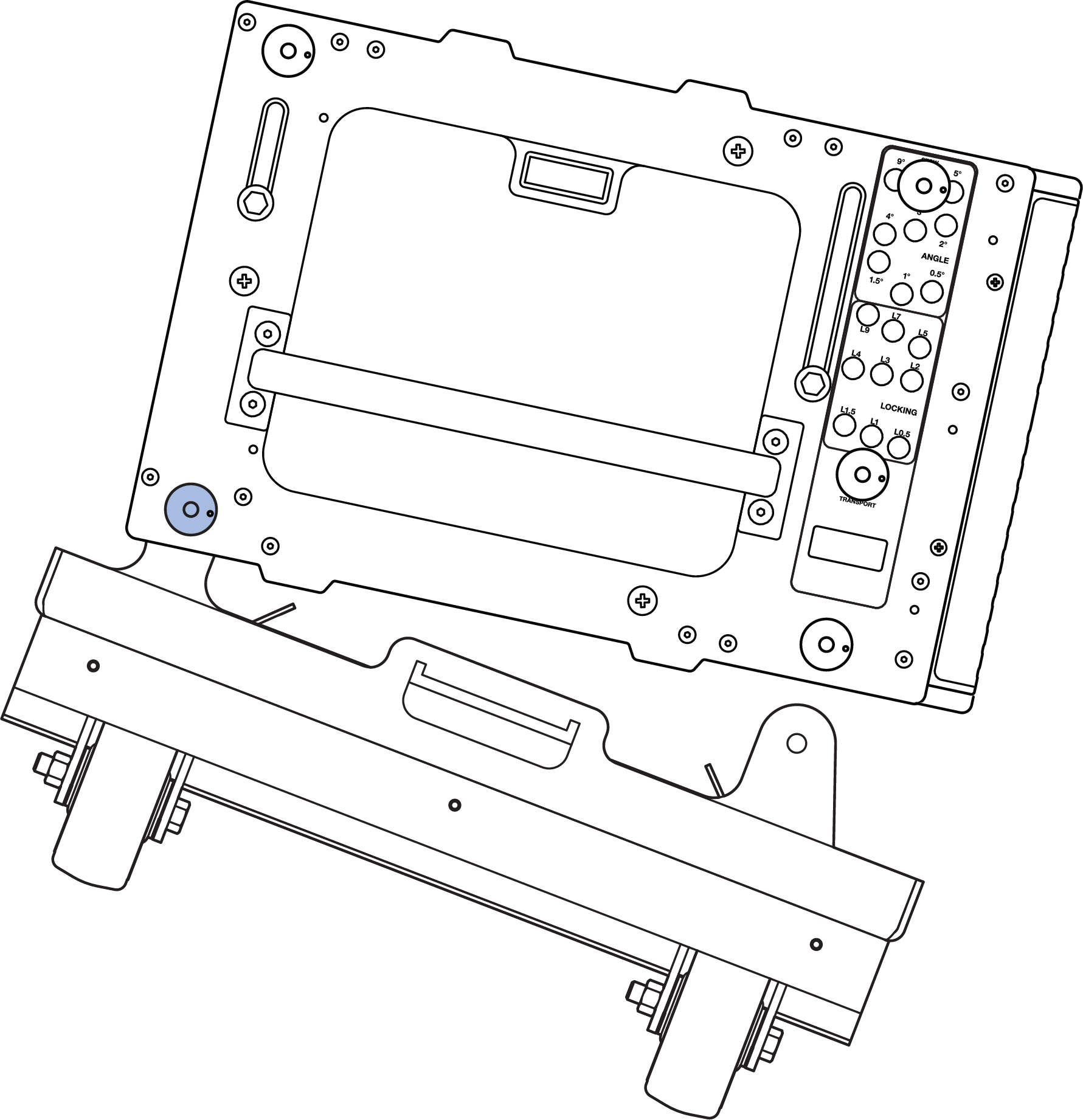
Tip the array up until the centerline of the suspended bottom cabinet is parallel to the working surface, e. g., floor, ground, stage, etc.
Suspended PANTHER Array, Tilted Up to Connect to a Stack of PANTHER
Note
If the load of the array is entirely transferred to the front hoist and the bottom of the cabinet is not parallel to the working surface, use the PBF-LYON in the Pull-Up configuration to aid in connecting the rear GuideALinks, see Pull-Up Configuration Overview.
Move the stacked cabinets under the suspended cabinets, aligning the corners.
Make sure the GuideALinks of the top stacked cabinet are retracted.
Caution
Do not attempt to “land” the suspended cabinets on a stacked cabinet with the GuideALinks extended. Collision of the GuideALinks and the GuideALink sockets will cause excessive wear over time. Collision of an extended GuideALink and the wooden bottom of a cabinet above it can puncture or damage the cabinet.
Lower the suspended cabinets within 1 to 2 inches (2.5 to 5 cm) above the top of the cabinet to be connected.
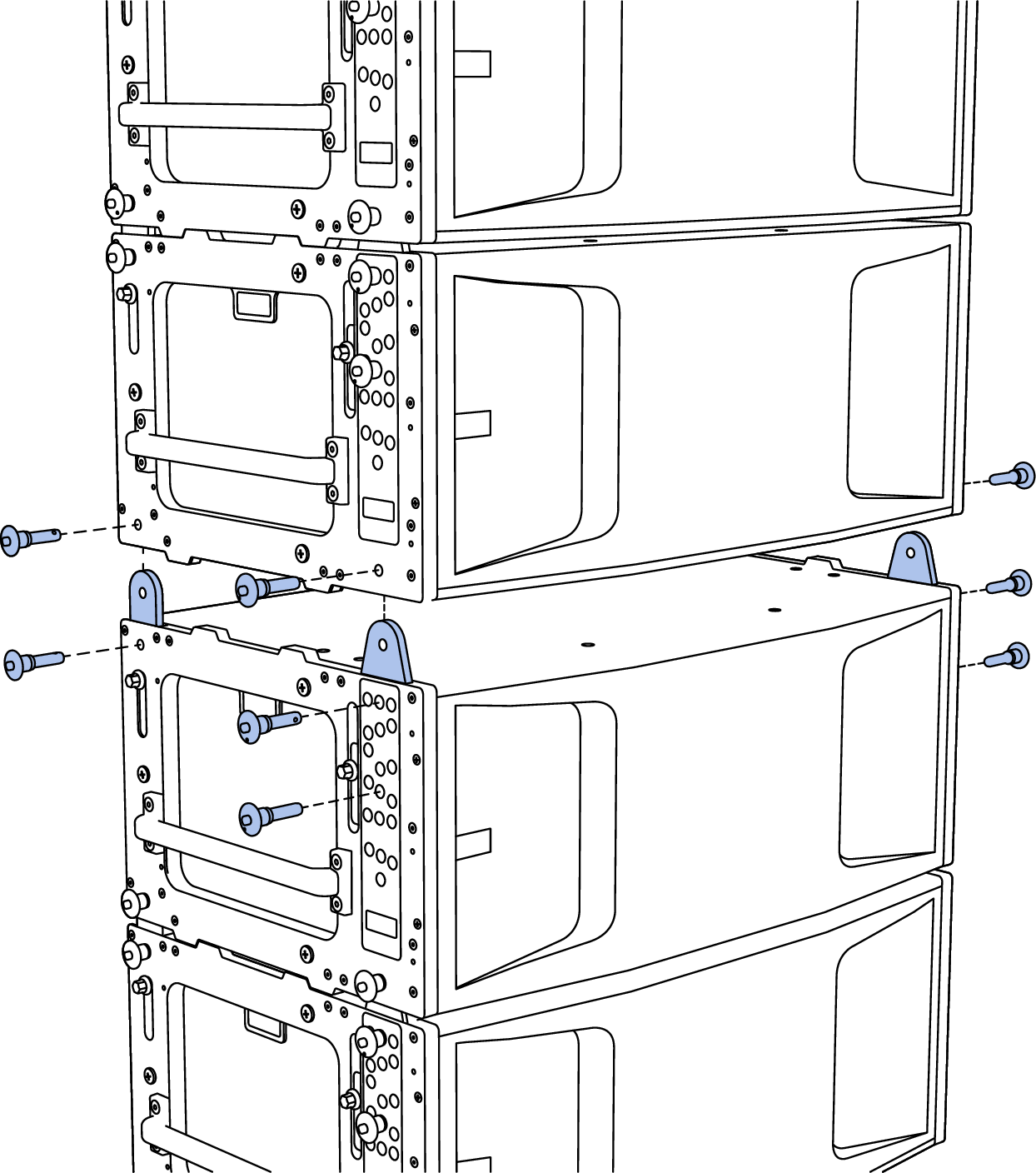
Connect the next stack of loudspeakers.
Extend the front GuideALink into the link socket of the suspended cabinet and secure it to the suspended cabinet with the 7/16 x 0.90-inch QRP (black button, PN 134.065) attached by lanyards to PANTHER cabinets. Remove the quick-release pin in the gray-on-black ANGLE holes if the front
Lower the suspended cabinets within 1 to 2 inches (2.5 to 5 cm) above the top of the cabinet to be connected.
The front GuideALinks keep the flown cabinets aligned to the stacked cabinets
If removed, replace the quick-release pin in the gray-on-black ANGLE hole of the top cabinet being connected.
Extend both rear GuideALinks into the suspended cabinet and secure them with the 7/16 x 0.90-inch QRP (black button, PN 134.065) attached by lanyards to PANTHER cabinets.
Note
The lanyards of the quick-release pins may be damaged if quick-release pins are inserted in an adjacent cabinet.
Rear GuideALink Extended, Secured with Two Quick-Release Pins
Caution
Make sure the quick-release pins are fully inserted and locked, unable to be removed without depressing the button of the quick-release pin.
During array assembly, the bottom of longer arrays can move forward and backward a significant distance when minor changes to the hoist elevations are made. Keep the area in front of and behind the array clear of personnel and equipment to avoid unintentional impact.
Repeat Steps 9-14 for each additional stack of PANTHER cabinets to be added to the array.
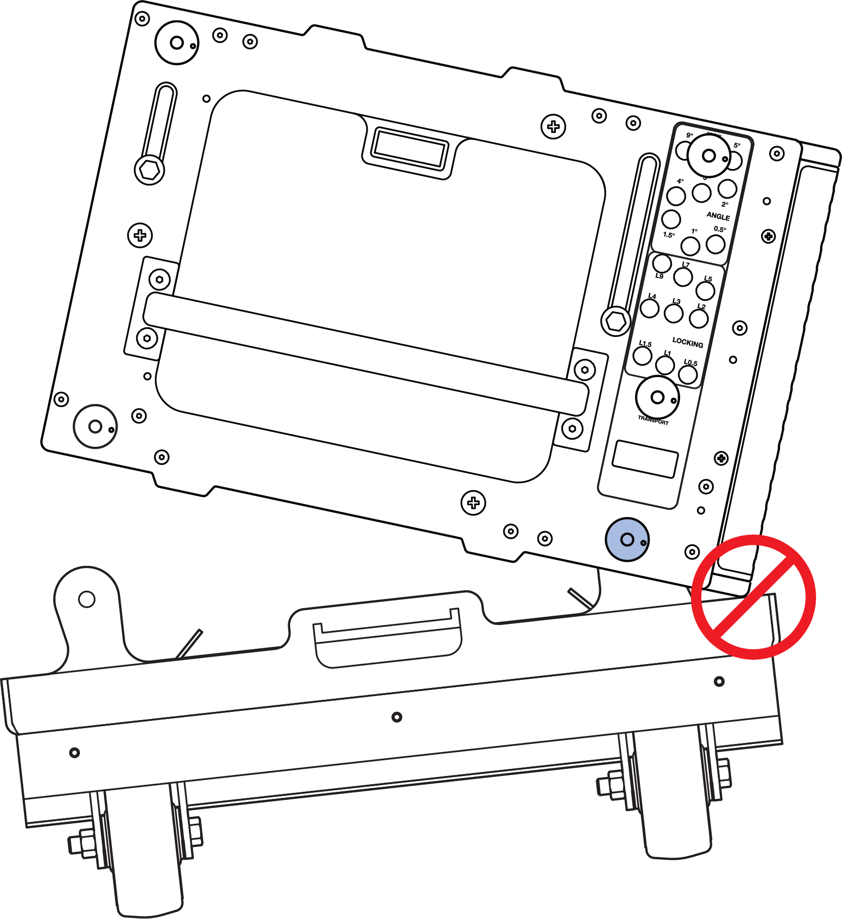
See the Array Assembly Notes if it is not possible to tip the suspended cabinets enough to connect the rear GuideALinks of the stacked cabinets to the suspended cabinets because the rear hoist becomes slacked, carrying no weight.
Unable to Tip Suspended Cabinets Enough to Connect Rear GuideALinks.
Connect PBF-LYON for pull-up or pull-back configurations.
Raise the array enough to remove the caster frame. Connect the PBF-LYON Pull Back Frame to the bottom cabinet.
Connect sufficiently rated hardware to the pull-back frame to form a bridle.
For a pull-up configuration, connect the bridle of the pull-back frame to a manual hoist, which is connected to the utility point on the shackle bar.
For the pull-back configuration, connect the bridle of the pull-back frame to the pull-back hoist.
Before Raising the Array
Make sure all cabinet-to-cabinet GuideALinks are secured with the 7/16 x 0.90-inch (black button) quick-release pins (PN 134.051) included with PANTHER cabinets.
Make sure the connected rigging hardware is properly aligned, especially the shackles.
Make sure the connected cabling has enough slack to not be strained and won’t be pinched or snag as the array is lifted.
If using a single hoist, verify the tilt angle of the MG-PANTHER Grid Kit matches the array design.
Note
At this point in the assembly process, users typically terminate the power, signal, and network cabling and verify proper signal patching.
Transitioning to Pull-Back Configuration
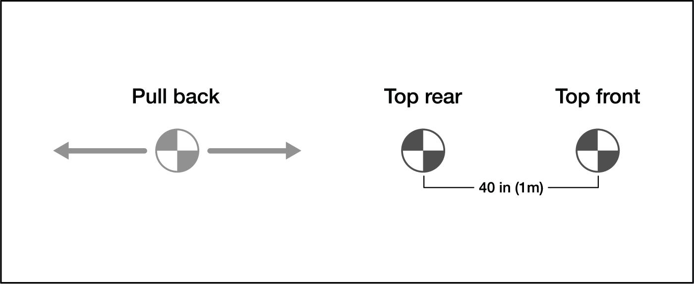
When suspending an array configured for pull-back, follow these steps to transition the load of the array from the two hoists connected to the MG-PANTHER Shackle Bar to the pull-back hoist and the rear hoist connected to the MG-PANTHER Shackle Bar , as shown in the figure below.
Caution
During the transition, tension of the rigging hardware is likely to be relieved which increases the likelihood shackles will become misaligned or “fouled”. Make sure all rigging remains properly aligned during array assembly and positioning.
With the pull back hoist not taking weight, raise all three hoists until the array is at the approximate trim height.
Raise the pull-back hoist until it begins to carry weight.
Lower the top front hoist until it no longer carries weight.
Raise the pull-back hoist until the desired grid angle is achieved.
Note
It may be necessary to lower the top front hoist if it approaches taking weight.
Raise or lower both the pull back and top rear hoists to achieve the desired trim height.
Raise the top front hoist until it just begins to take weight.
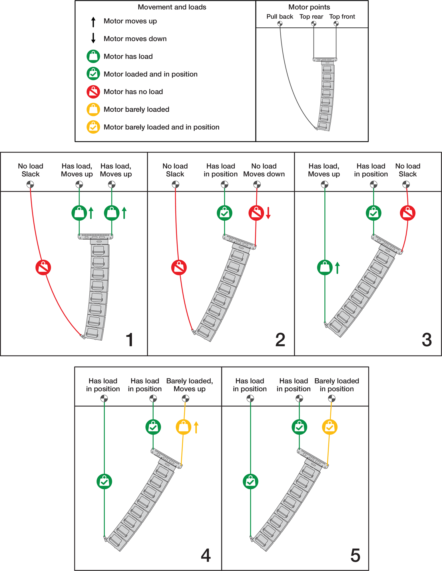
Transition to Pull Back Configuration Steps
Trim the array in its final position.
Raise the array to the designed trim height.
Note
The Reference Point, front or rear, is selected in MAPP. The front and rear Reference Points are located on the MG-PANTHER Shackle Bar.
MAPP Front and Rear Reference Point Locations on MG‑PANTHER Shackle Bar.
If using an MVP Motor V Plate, adjust the tension of the connected hoists to rotate the array.
Verify and adjust as needed: height, grid angle, and horizontal rotation until the design parameters are achieved. Adjusting the grid angle
Note
When using one hoist or if most of the array weight is transferred to one hoist, the array may tend to rotate, changing the horizontal aim. In this case, use rigging hardware secured to the rigging elements of the array to prevent rotation.
Array Assembly Notes
Longer Arrays or Large Total Splay Angle
For arrays of 16 cabinets or smaller arrays with large splay angles it may not be possible to tip the suspended
cabinets enough to connect the rear GuideALink. If the rear hoist becomes slack before the center line of the bottom suspended cabinet is close to parallel to the working surface, use one of the following methods.
Rear GuideALinks Retracted
Option One
With the front GuideALinks connected, remove the white-on-gray LOCK quick-release pin from the bottom suspended cabinet.
Remove Lock Pin of Bottom Suspended Cabinet
Lower the suspended cabinets and connect the rear GuideALink.
Lift the hoists and replace the previously removed white-on-gray LOCK quick-release pin.
Option Two
Set the front GuideALink gray-on-black ANGLE quick-release pin of the top stacked cabinet to 9 degrees, allowing it to fully extend. This maximizes the angle between the cabinets before the front edges of the cabinets collide.
With the caster frame attached and the front GuideALinks of the stacked cabinets connected to suspended cabinets, tension both hoists.
Raise the hoists until the front GuideALinks fully extend, with little of the weight supported by the caster frame wheels.
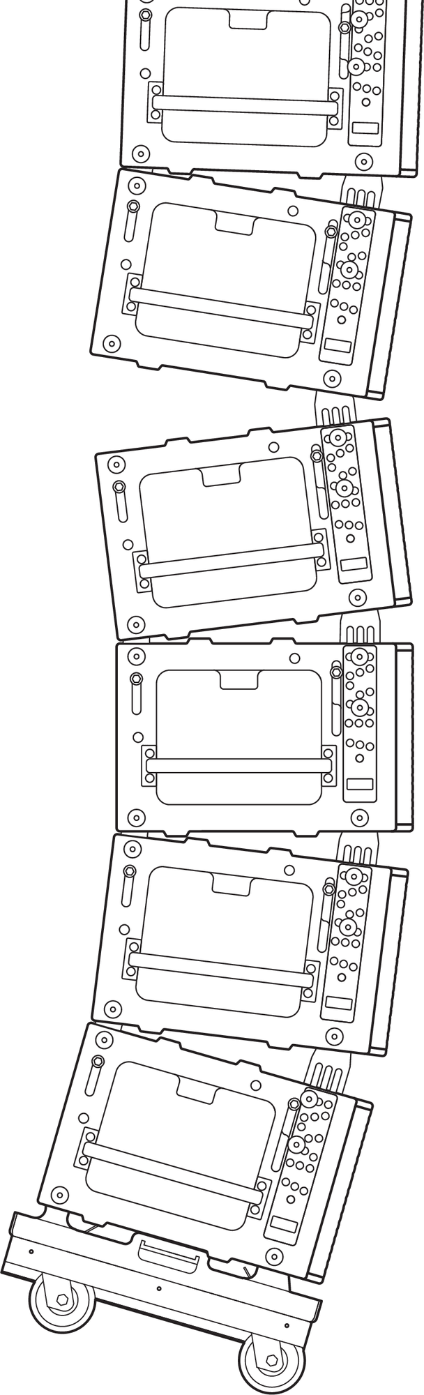
Hoists Lifting, Front GuideALinks Extend
Using the handles on both sides of the two cabinets closest to the working surface, pull the stack backwards while lowering the hoists. The gap at the rear of the suspended and stacked cabinets will close.
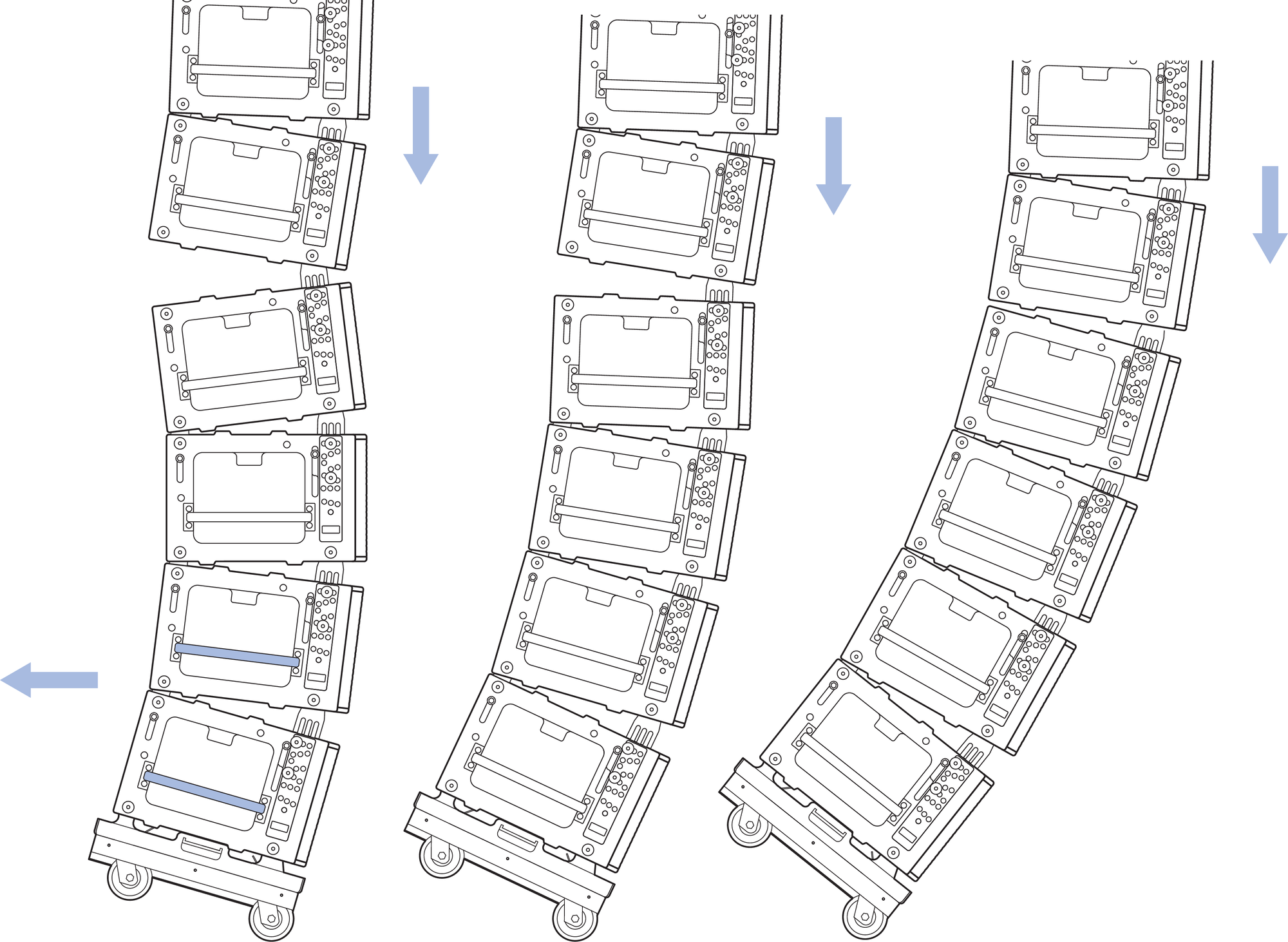
While Pulling the Stacked Cabinets Towards the Rear, Lower the Hoists.
Move the gray-on-black ANGLE quick-release pin that was previously moved to the 9 degree hole, back to its original hole.
Option Three
With the front GuideALinks connected, move the gray- on-black ANGLE quick-release pin of the top stacked cabinet to 9 degrees, allowing it to fully extend. This maximizes the angle between the cabinets before the front edges of the cabinets collide.
Raise the hoists enough to remove the caster frame, detaching the front first.
Connect the PBF-LYON Pull Back Frame to the bottom cabinet.
Connect the bridle of the PBF-LYON Pull Back Frame to a manual hoist connected to the utility point on the MG-PANTHER Shackle Bar.
Tension the hoist to close the gap in the rear between the suspended and stacked cabinets.
Move the gray-on-black ANGLE quick-release pin that was previously moved to the 9 degree hole, back to its original hole.
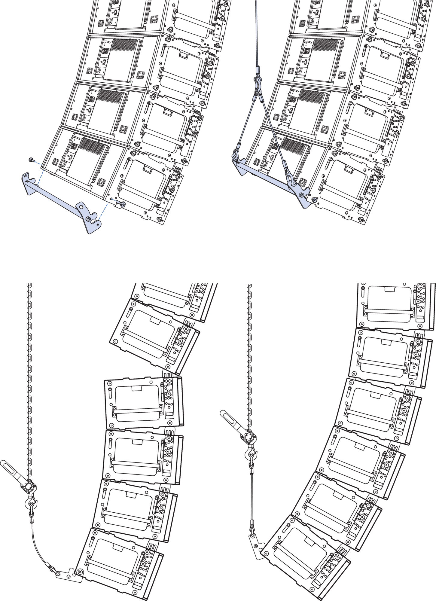
Attach PBF-LYON and Tension to Connect Rear GuideALink.
Inserting Quick Release Pins in LOCK Holes
If it is not easy to insert a white-on-gray LOCK quick- release pin due to the end frame and GuideALink holes not aligning, rotate the array so the line at the bottom of the front GuideALink label of that cabinet is parallel to the working surface, as shown in the figure below. Adjust the hoists in small increments up and/or down to align the GuideALink and the end frame holes as needed.
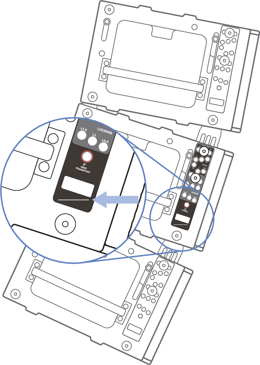
Label Alignment Line Parallel to Working Surface.
Stacking Caster Frames
The MCF-PANTHER caster frames can be stacked atop one another for storage. When stacking, tip the caster frame enough that all the wheels rotate the same direction, then lower the caster frame onto another.
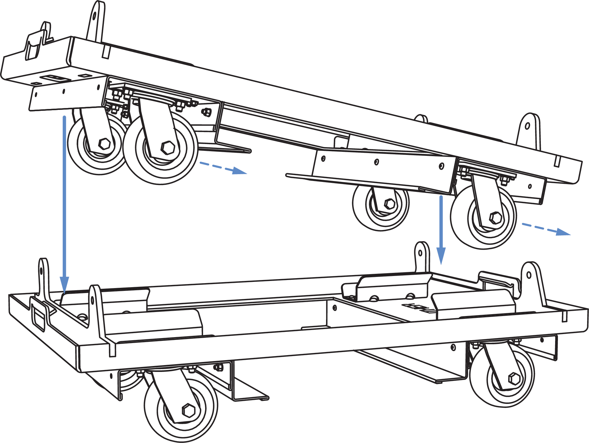
MCF-PANTHER Caster Frame Stacking, Tip to Rotate Casters, Lower to Stack
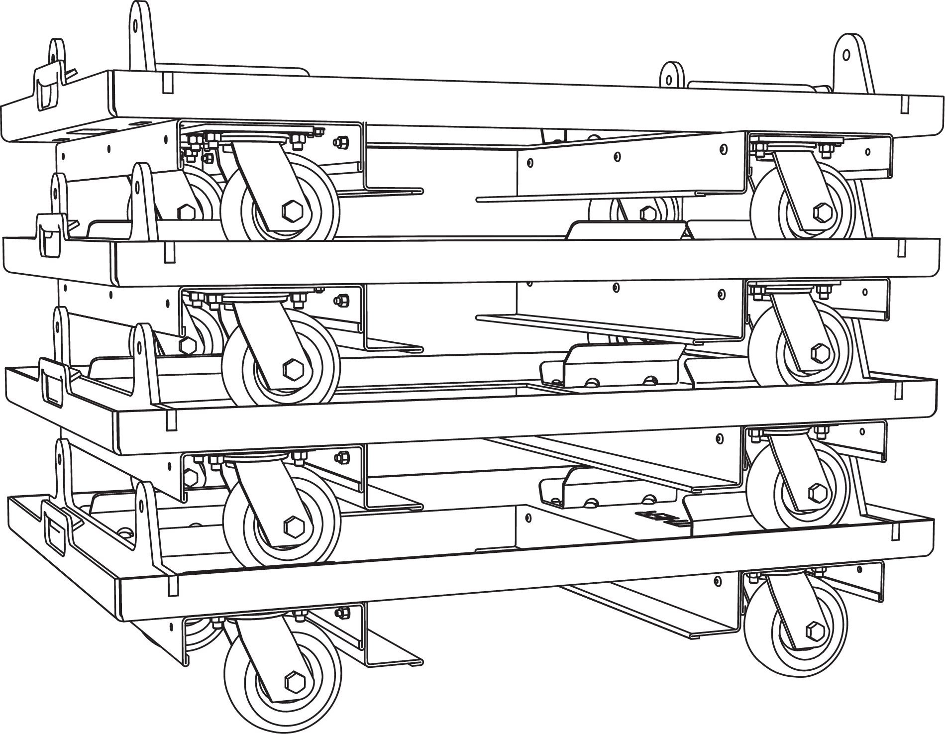
MCF-PANTHER Caster Frames Stacked
Outdoor Use
When deployed outdoors, it is common to secure the bottom of an array to structural points to prevent movement due to light wind.
It is typical to “land” arrays when there are high winds or when staff is not on site, e. g., overnight at a festival. When landing an array, protect the bottom front corner of the bottom PANTHER by either adjusting the array so the bottom PANTHER is parallel to the working surface or attaching an MCF-PANTHER Caster Frame.
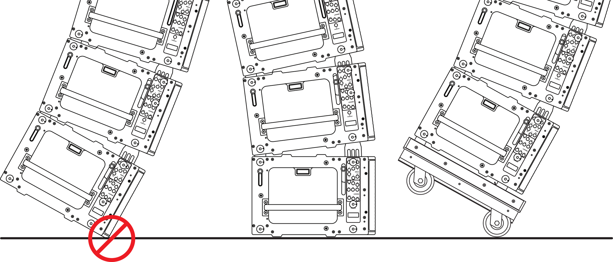
Only “Land” Array When Bottom Cabinet is Parallel to Surface or When Caster Frame is Attached
Disassembling Arrays
Array Disassembly Preparation
De-energize the electrical system providing power to the loudspeakers.
Disconnect cabling connected to equipment on the ground.
Disconnect any rigging hardware used to secure the horizontal aim of the array.
If the array is dead hung (required in some regions), raise the hoists so they take weight and remove the rigging hardware associated with the dead hang.
Array Disassembly Steps
Before lowering the array, make sure that attached cabling has enough slack and that the area around and under the array is clear of obstructions.
Caution
Discover and follow all safety regulations and operational rules regarding movement of suspended loads for the region, location, and venue before disassembling an array.
For arrays in the pull back configuration, follow these steps (see Figure 82):
Lower the pull back hoist until it does not carry weight.
Note
The top front hoist will slack, if the rigging will likely “foul” or become misaligned, raise the top front hoist to reduce slack in rigging without taking weight.
Once the pull back hoist is slack, raise the top front hoist.
Note
If the pull back hoist is about to take weight, lower it further.
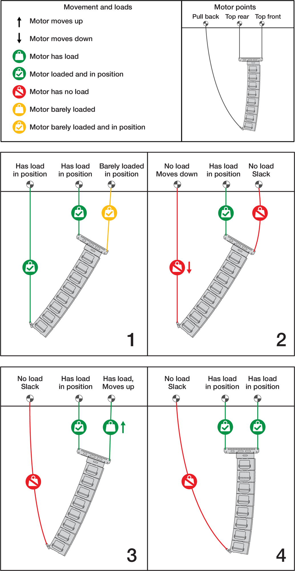
Transition From Pull Back Configuration Steps
When using two hoists connected to the MG-PANTHER Shackle Bar, lower the hoist carrying the greater weight to approximately equalize the weight carried by each hoist.
Lower the array to within 3 ft (1 m) of the working surface and tip the array up, making the bottom cabinet more parallel with the working surface.
Lower the array until the bottom cabinet is 1 to 2 inches (2.5 to 5 cm) above the height of an MCF-PANTHER Caster Frame and move an MCF-PANTHER under the cabinets.
Connect an MCF-PANTHER to the bottom of the array.
Caution
Always lift and pin the rear of the MCF-PANTHER Caster Frame first, then the front. If the front is pinned first and the rear of the caster frame is not supported, the caster frame can swing down, contacting and potentially damaging the PANTHER cabinet.
Remove all four of the quick-release pins from the bottom GuideALink sockets of the PANTHER cabinet.
Caution
When attaching caster frames to cabinets, do not use the handles to lift the caster frame. There is a hand pinch point (see Figure 65). The handles are only intended to be used when lifting or carrying a caster frame not attached to a cabinet.
Lift the rear of the caster frame from the underside of the caster frame.
Seat the rear tabs of the caster frame in the rear GuideALink sockets of the cabinet and insert the previously removed quick-release pins to secure the rear of the caster frame.
Next, lift the front of the caster frame by lifting from the underside of the caster frame.
Seat the front tabs of the caster frame in the front GuideALink sockets of the cabinet and insert the previously removed quick-release pins to secure the front of the caster frame.
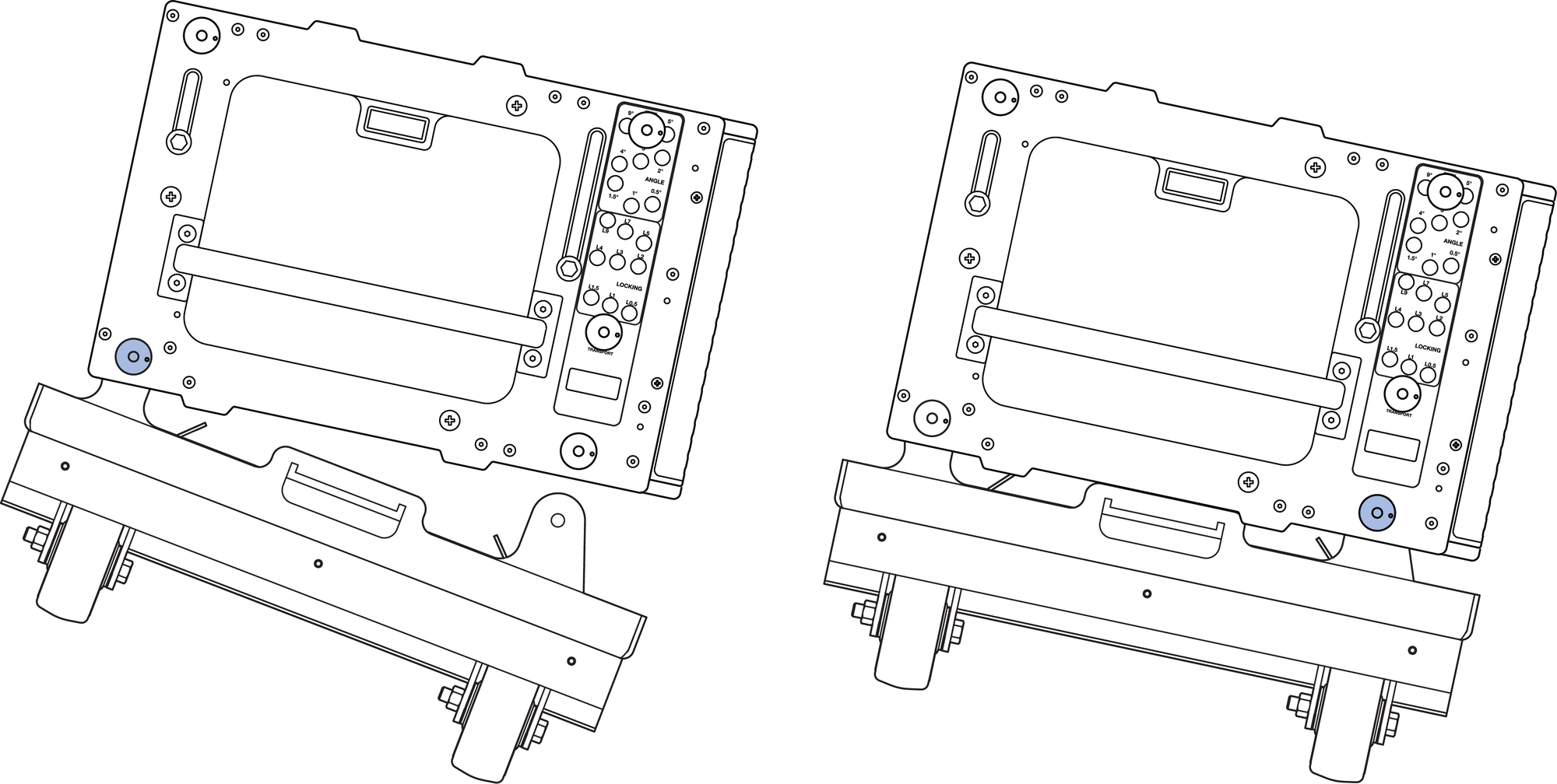
Connect the Rear of the MCF-PANTHER Caster Frame First, Then the Front
Do Not Connect the Front of the MCF-PANTHER Caster Frame First
Lower the array until the either the front or rear caster frame wheels contact the working surface.
Disconnect all cabling from the cabinets to be removed from the array.
Remove the quick-release pin in the white-on-gray LOCK holes of the cabinets to be disconnected from the array.
Note
Small adjustments of the hoists may be necessary to relieve tension or compression of the front GuideALinks.
Lower the array until the front GuideALinks are no longer extended.
Move the quick-release pins in the gray-on-black ANGLE holes of the cabinets to be disconnected from the array to the STOW / GRID 7° holes.
Remove the quick-release pin securing the rear GuideALink of the top cabinet to be disconnected from the array.
Note
Small adjustments of the hoists may be necessary to relieve tension or compression of the rear GuideALinks. Lower the link and secure with the quick-release pin.
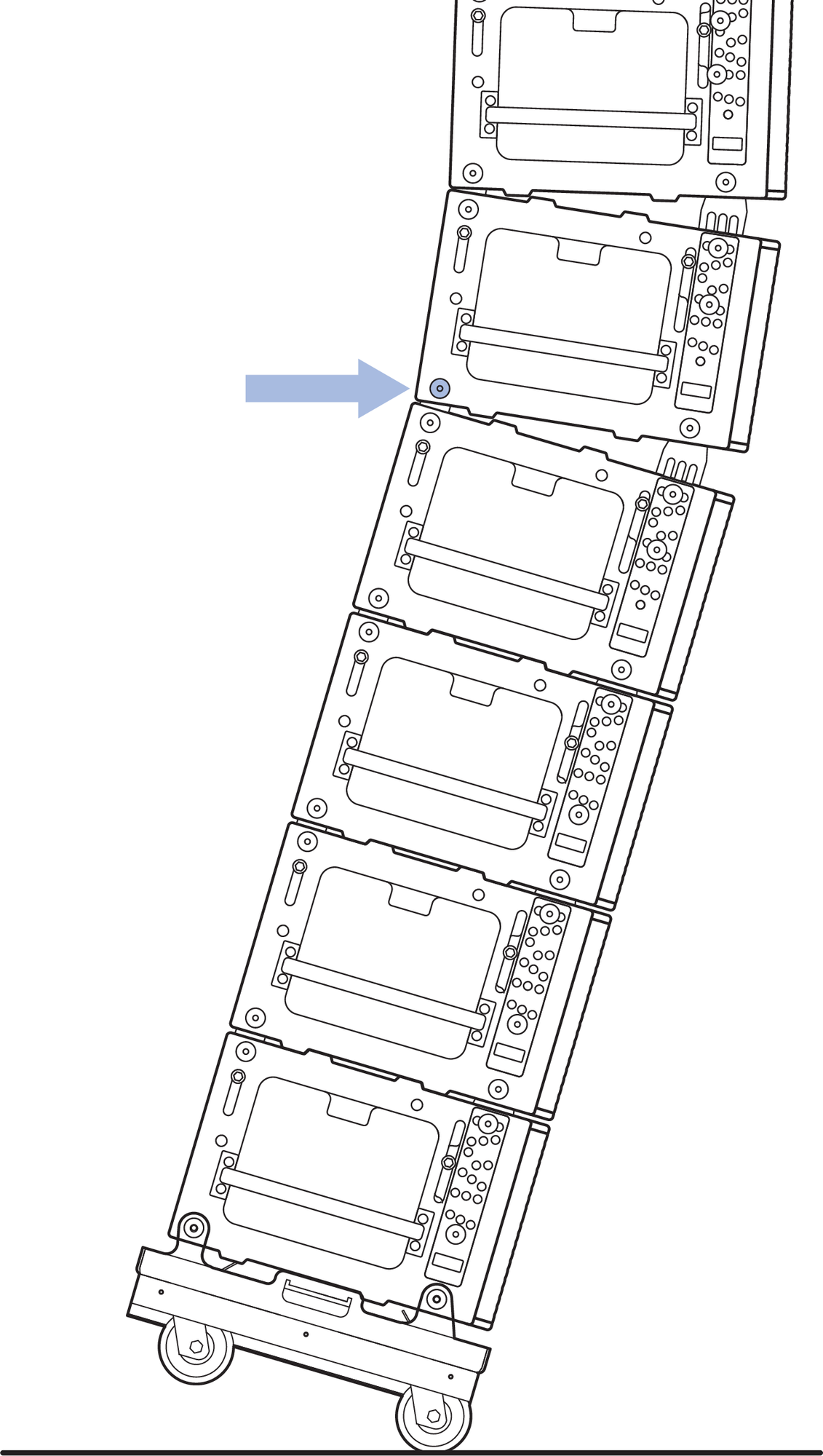
. Remove the Quick Release Pin Securing the Rear GuideALink
Raise the hoists until the quick-release pin securing the front GuideALink can easily be removed.
Prepare the stack to be transported.
The quick-release pins can be in any of the gray-on- black ANGLE holes.
For each cabinet, insert a quick-release pin in the white-on-gray LOCK hole labeled 0° GRID / TRANSPORT.
Caution
When PANTHER loudspeakers are stacked in the MCF-PANTHER caster frame, the splay angles should all be 0°. The front and rear GuideALinks of each cabinet should be extended and secured in place with quick-release pins connecting each cabinet of the stack to one another. For stacks that do not include the MG-PANTHER Grid Box, retract the GuideALinks of the top cabinet.
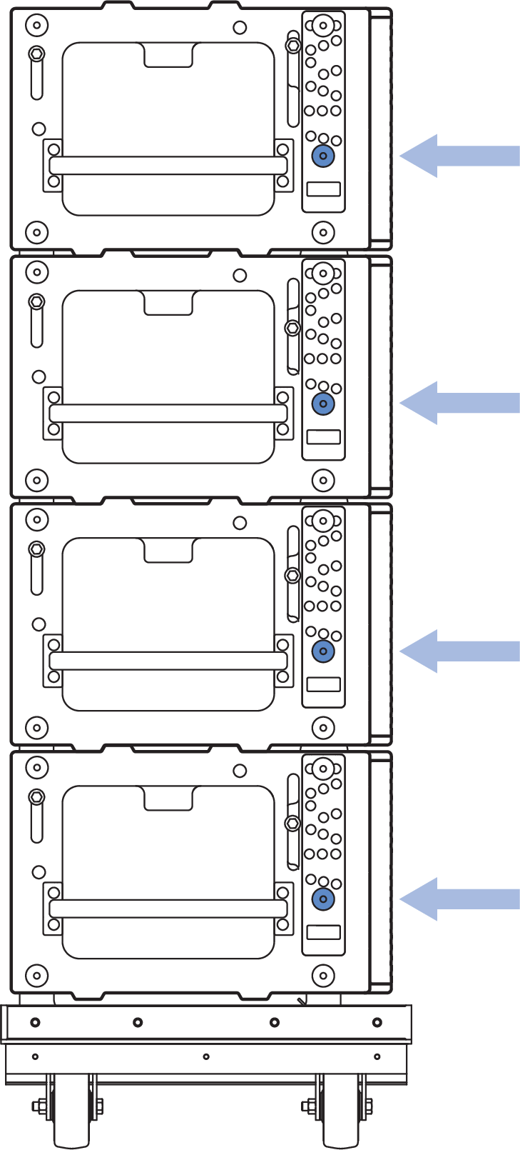
Quick-Release Pins in LOCK Hole Labeled 0° GRID / TRANSPORT.
Move the stack of cabinets from under the suspended array.
Open the flap of the 4-high cover and slide over the top of the stacked cabinets.
Repeat Steps 5-13 for additional stacks of cabinets.
Transporting MG-PANTHER Grid Box on Cabinets
When transporting a MG-PANTHER Grid Box on a stack of cabinets, use the front and rear GuideALinks to secure the MG-PANTHER Grid Box to the top cabinet. This is the same configuration of the GuideALinks as when the array is suspended.
Remove both quick-release pins of the front GuideALink and raise the link into the GuideALink socket of the MG-PANTHER Grid Box.
Insert a pin in the white-on-gray LOCK hole labeled 0° GRID / TRANSPORT and another in the gray-on- black ANGLE hole labeled STOW / GRID 7°.
Insert the 7/16 x 1.50-inch QRP (red button, PN 134.051) quick-release pins included with the MG-PANTHER Grid Box to secure the cabinet to the MG-PANTHER Grid Box.
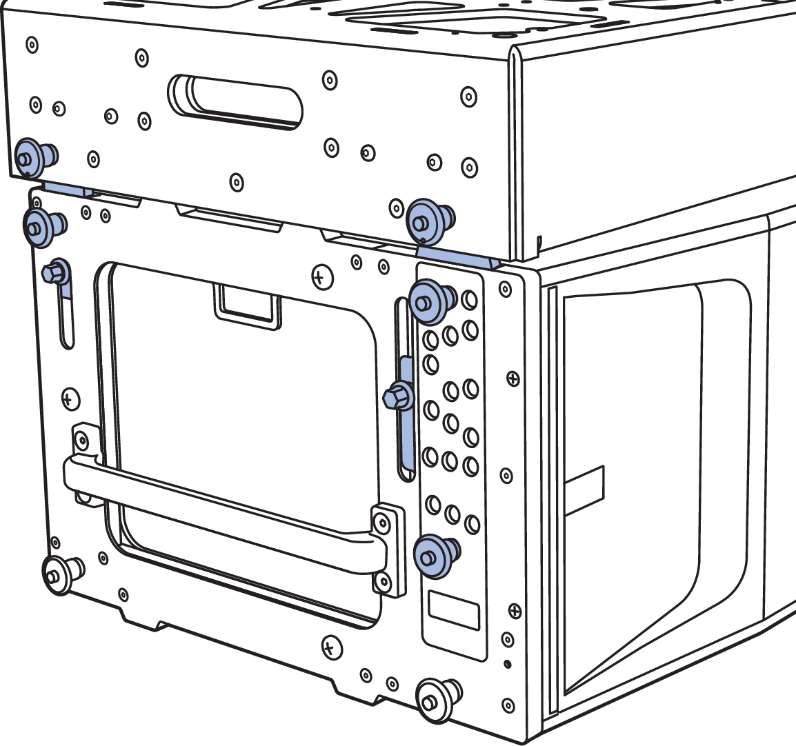
GuideALinks Extended and Secured with Quick-Release Pins
Caution
Do not transport 4-high stacks of PANTHER with the MG-PANTHER Shackle Bar attached to the MG-PANTHER Grid Box. This exceeds the safety limits for tip-over, which may cause injury.
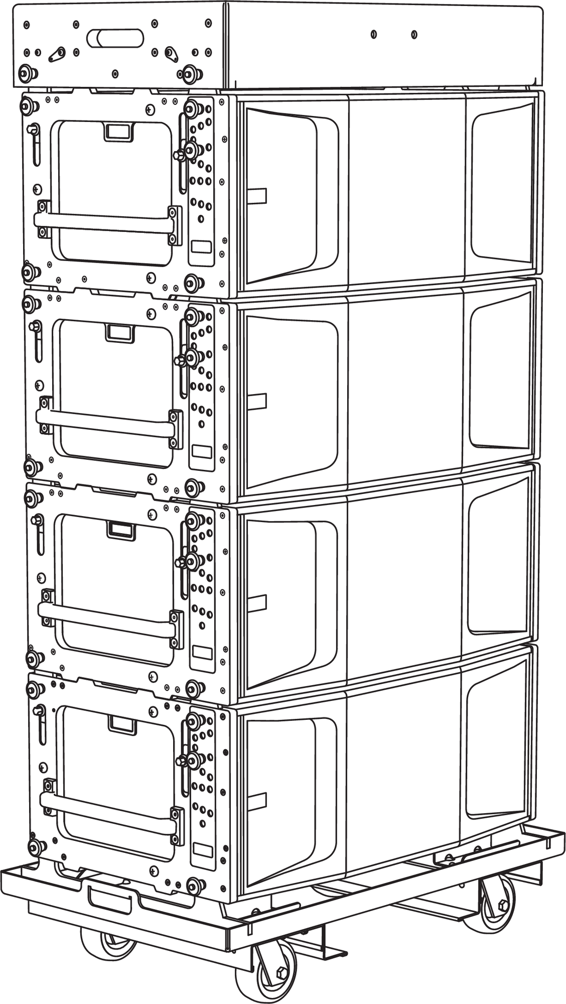 |
MG-PANTHER Shackle Bar Removed, MG-PANTHER Grid Box, PANTHER Cabinets, and MCF-PANTHER Caster Frame