Operating Instructions — MM-4XP
Miniature loudspeaker
The MM-4XP miniature loudspeaker is a self-powered loudspeaker designed for high-quality distributed systems. Housed in a compact aluminum enclosure, the MM-4XP is especially suitable for installations involving space limitations and visibility concerns. The loudspeaker’s proprietary 4-inch cone transducer, manufactured at Meyer Sound's Berkeley factory delivers a linear peak SPL of 111.5 dB with crest factor > 16.5 dB, and has a wide operating frequency range of 120 Hz to 18 kHz with very low distortion. The MM-4XP exhibits the same high intelligibility and flat frequency and phase responses for which Meyer Sound loudspeakers are known. Peak and rms limiters regulate loudspeaker temperatures and excursion, ensuring that the MM-4XP performs exceedingly well even when driven into overload.
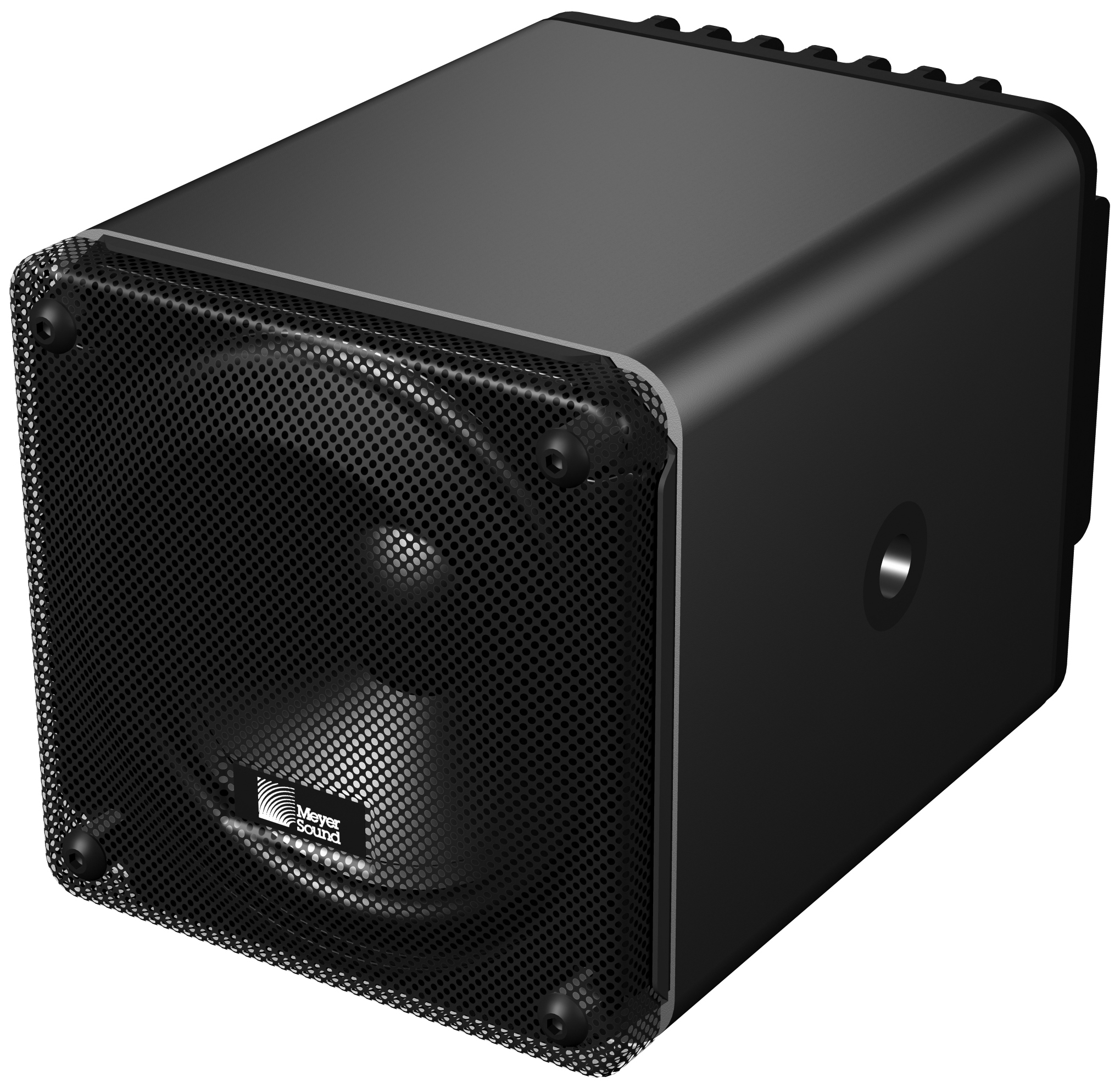
MM-4XP Loudspeaker
The MM-4XP's amplifier and signal-processing circuits are designed to store DC power and tolerate voltage drops, thereby accommodating light-gauge cables and long cable runs. The MM-4XP receives balanced audio and DC power from a SwitchCraft® EN3™ 5-pin male connector on its rear panel.
MM-4XP loudspeaker systems require a Meyer Sound external power supply (see meyersound.com/product/mps for more information). The MPS-488HP single-space 19-inch rack unit receives eight channels of balanced audio from its XLR female inputs and routes the audio, along with 48 V of DC power, to its eight channel outputs. The outputs—equipped with either Phoenix 5-pin male connectors on the MPS-488HPP model, or EN3 5-pin female connectors on the MPS-488HPE model—can deliver DC power to the MM-4XP loudspeakers at cable lengths of up to 300 feet with just 1 dB of loss in peak SPL using 18 AWG wire. The use of composite multiconductor cables (such as Belden® 1502) allows a single cable to carry both audio and DC power to the MM-4XP. Longer cable lengths are possible for moderate applications that don't drive the loudspeakers to maximum output, or for installations with heavier wire gauges. The smaller MPS-482HP provides two channel outputs via 5-pin male Phoenix connectors.
 |
MPS-488HPP Power Supply
The MM-4XP’s extruded aluminum enclosure acts as a heat sink to dissipate heat from the driver's voice coil. The enclosure is available in standard white or black anodized finishes with a perforated steel grille. It can also be custom painted to match specific color schemes.
The MUB-MM-4XP U-bracket mounts the loudspeaker on walls and ceilings at adjustable angles. The U-bracket is also available in standard white or black anodized finishes and custom colors.
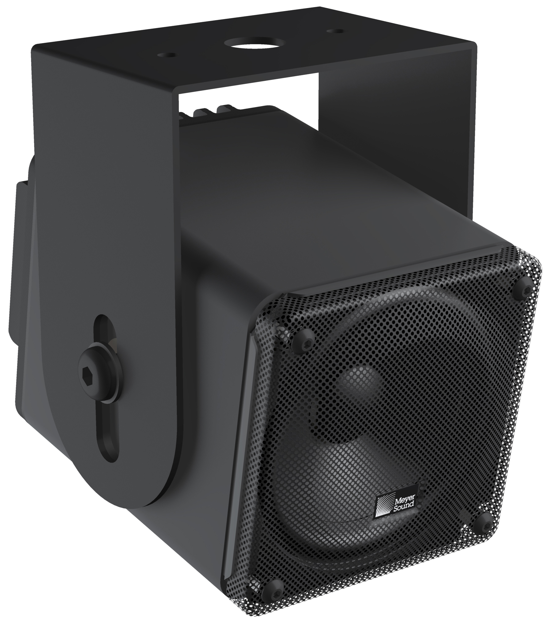 |
MM-4XP Loudspeaker Mounted with MUB-MM-4XP U-Bracket
The MM-4XP connectors
The MM-4XP receives DC power and balanced audio from an EN3 5-pin male connector on its rear panel. The connector’s five pins include two for DC power (negative and positive) and three for balanced audio (shield, negative, and positive). To function properly, the MM-4XP requires 48 V of DC power. A female EN-3 5-pin cable-mount connector is included with each loudspeaker (PN 468.069).

MM-4XP Connector
A single composite cable (such as Belden 1502) wired for both DC power and balanced audio can be used to connect the MM-4XP to one of the MPS-488’s eight or the MPS- 482’s two channel outputs.
Warning
Applying DC power to the audio signal contacts will damage the loudspeaker and is not covered by the warranty. Always ensure that cables are assembled correctly.
Wiring the EN3-to-Pigtail Cables
Each MM-4XP loudspeaker comes with one EN3 5-pin female to pigtail cable. The EN3 end of the cable connects directly to the MM-4XP connector. The pigtail end of the cable can be equipped with either an EN3 5-pin male connector for connecting to the MPS-488HPE power supply, or a Phoenix 5-pin female connector for connecting to the MPS-488HPP or MPS-482HP power supplies. The pigtail can also be spliced to a longer loudspeaker cable or to a junction box. The included EN3-to-pigtail cable uses Belden 1502 cable, which can be wired for both DC power and balanced audio. The EN3-to-pigtail cable is available in plenum or regular (non-plenum) versions.
Note
For a complete list of cables and cable connectors available from Meyer Sound that can be used with the MM-4XP loudspeaker, see MM-4XP Accessories.
When assembling MM-4XP loudspeaker cables with the included EN3-to-pigtail cables, make sure to use the wiring scheme in Table 1. The red and black wires in Belden 1502 cable have a thicker gauge than the other three wires and should be used for DC power. The blue, white, and shield wires should be used for audio.
 |
Belden 1502 Composite Cable
Note
For details on assembling MM-4XP loudspeaker cables, see Assembling Loudspeaker Cables.
Wire | Gauge | Signal |
|---|---|---|
Red | 18 AWG | DC power, positive (+) |
Black | 18 AWG | DC power, negative (–) |
White | 22 AWG | Balanced audio, positive (+) |
Blue | 22 AWG | Balanced audio, negative (–) |
Shield | 24 AWG | Balanced audio, shield |
When wiring MM-4XP cables, it is extremely important that each pin in the cable be wired so that the pins in the MM-4XP connector align with those in the MPS channel output connector (see “Channel Outputs”). Make sure the 48 V DC from the MPS power supply is wired directly (and only) to the 48 V DC pins on the MM-4XP connector, and that the polarity is observed (negative to negative, positive to positive) to avoid damage to the loudspeaker. In addition, make sure the audio pins are wired correctly; polarity reversals for audio signals can affect system performance.
Note
For information on MM-4XP cable requirements, see MM-4XP Current Draw and Cable Requirements.
MM-4XP Current Draw and Cable Requirements
Each MM-4XP loudspeaker draws a maximum current of 0.7 A rms and 2.2 A peak from the 48 V DC output of the MPS power supply. The current draw for the MM-4XP is dynamic and fluctuates as operating levels change. The cabling between the MM-4XP and the MPS power supply adds resistance and hence causes a voltage drop at the loudspeaker. Because lower voltages compromise peak SPL, and in some cases frequency response, cable resistance should be minimized.
Note
When connecting an MM-4XP to an MPS channel output, the total cable resistance should not exceed 4 ohms.
Cable Lengths and Cable Gauges for MM-4XPs
When connecting an MM-4XP to an MPS channel output, you can use cable lengths of up to 300 feet with only 1 dB of peak SPL loss using 18 AWG wire. Longer cable lengths are possible with heavier wire gauges (see tables MM-4XP Loudspeaker Cable Lengths (AWG) and MM-4XP Loudspeaker Cable Lengths (European) below).
Note
For music playback at moderate levels (when the MM-4XP is not driven to maximum output), cable lengths of up to 500 feet with 18 AWG wire are acceptable.
Cable Gauge | Resistance (Ω/ft) | Approximate Max. Length |
|---|---|---|
12 AWG | 0.0016 | 1200 ft |
14 AWG | 0.00253 | 750 ft |
16 AWG | 0.00402 | 475 ft |
18 AWG | 0.00636 | 300 ft |
20 AWG | 0.01008 | 175 ft |
Cable Gauge | Resistance (Ω/m) | Approximate Max. Length |
|---|---|---|
2.50 mm2 | 0.0052 | 365 m |
1.50 mm2 | 0.01076 | 175 m |
1.00 mm2 | 0.02087 | 90 m |
0.75 mm2 | 0.03307 | 55 m |
The maximum cable length for an MM-4XP can be calculated with the following formula:
maximum length = 4 Ω / 2 * cable resistance (in Ω/ft)
For example, the maximum length of an 18 AWG cable with a resistance of 0.00636 Ω/ft is equal to 314.4 feet
(4 Ω/ 2 * 0.00636 Ω/ft).
Note
For long cable runs, you can use large cable gauges for most of the run and then terminate with the included EN3-to-pigtail cable.
The MM-4XP LED
The MM-4XP has a three-color LED on its rear panel that changes color to indicate the loudspeaker’s status.
Powering On (Green)
When powering up the MM-4XP loudspeaker, the following startup events occur and are indicated by the LED:
The LED flashes green and then yellow during power up.
The LED turns solid green indicating the loudspeaker is ready to reproduce audio.
Caution
If the MM-4XP LED turns red and stays solid red after powering up and the audio is muted, the loudspeaker has encountered a failure and may need to be serviced. Contact Meyer Sound Technical Support.
If the MM-4XP LED turns solid red and the loudspeaker continues to output audio, though at reduced levels, the loudspeaker’s voltage may have dropped below 25 V DC. Operation of the loudspeaker under these conditions is not recommended and the loudspeaker’s power supply and cabling should be verified.
Limiting (Yellow)
Limiting activity is indicated when the MM-4XP LED turns yellow. When engaged, the limiter protects the loudspeaker’s driver and prevents signal peaks from causing excessive distortion in the loudspeaker’s amplifier, thereby preserving headroom and maintaining smooth frequency response at high levels. When the level returns to normal, below the limiter’s threshold, the LED turns green and limiting ceases.
The MM-4XP performs within its acoustical specifications at normal temperatures when the MM-4XP LED is green, or if the LED turns yellow for two seconds or less and then turns green for at least one second. If the LED remains yellow for longer than three seconds, that loudspeaker enters hard limiting where:
Increases to the input level have no effect.
Distortion increases due to clipping and nonlinear driver operation.
The driver is subjected to excessive heat and excursion, which will compromise its life span and may eventually lead to damage over time.
Caution
The MM-4XP LED turns yellow when the loudspeaker’s signal goes 2 dB beyond the actual onset of limiting, and indicates a safe, optimum level has been exceeded. If the MM-4XP loudspeakers in a system begin to limit before reaching the required SPL, consider adding more loudspeakers to the system to achieve the desired SPL without exposing the loudspeakers to excessive levels and possible overheating.
Loudspeaker Temperature and Limiting
The MM-4XP LED turns solid yellow when the temperature of the MM-4XP heatsink reaches 65° C (145° F), indicating the unit is reaching its maximum heat dissipation, and a reduction in SPL is recommended. While the MM-4XP will continue to operate while the LED is yellow, the limiter threshold is lowered to a safe level (causing the output level to be lowered by 6 dB) to prevent the loudspeaker from overheating. When the temperature of the MM-4XP heatsink cools to 50 °C (122 °F), the LED changes from yellow to green and the limiter threshold returns to normal.
Clipping (Red)
The MM-4XP LED flashes red when its input signal causes the amplifier to overload. If the LED flashes red continuously, the loudspeaker is severely overloaded and a reduction in the input level is recommended.
Caution
If the MM-4XP LED turns solid red and the loudspeaker continues to output audio, though at reduced levels, the loudspeaker’s voltage may have dropped below 25 V DC. Operation of the loudspeaker under these conditions is not recommended and the loudspeaker’s power supply and cabling should be verified.
Connecting MM-4XP Loudspeakers to a Meyer Sound Power Supply
Power off the MPS power supply.
Connect audio sources (from a mixer or processor) to the MPS channel inputs. Use balanced XLR cables.
Use the MPS link switches to route channel inputs to the desired channel outputs.
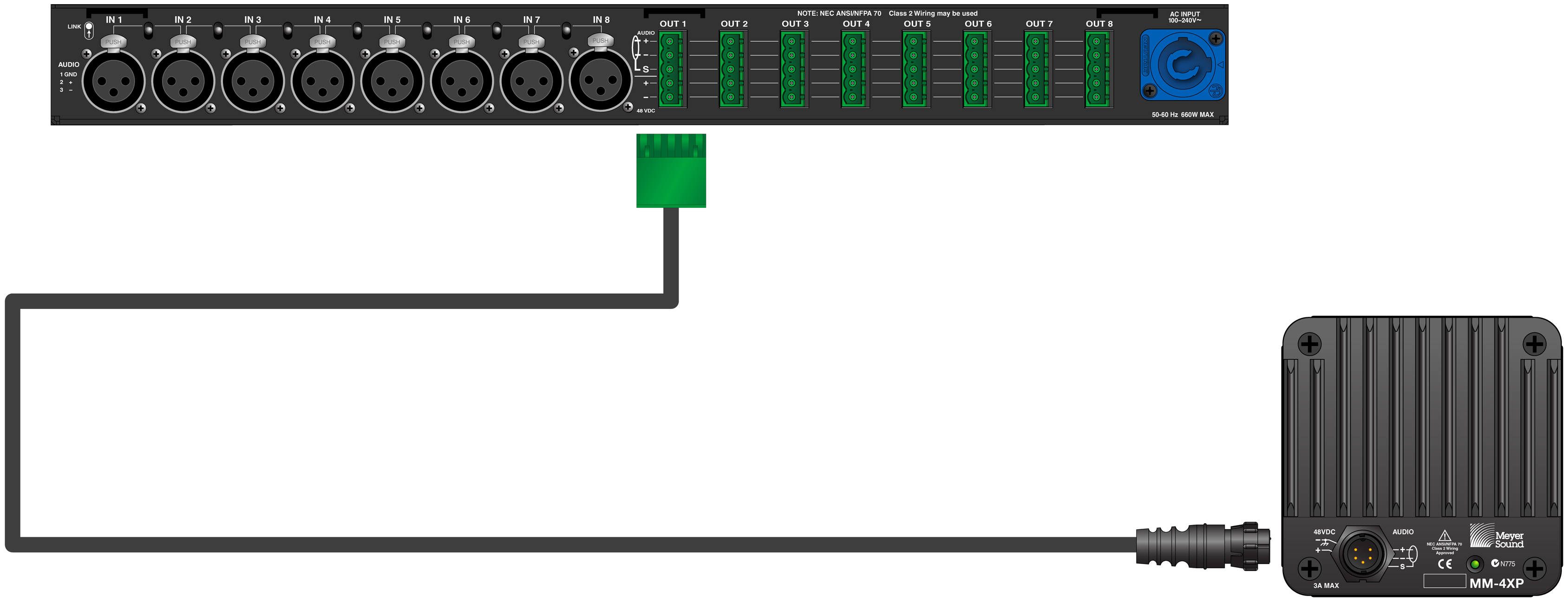
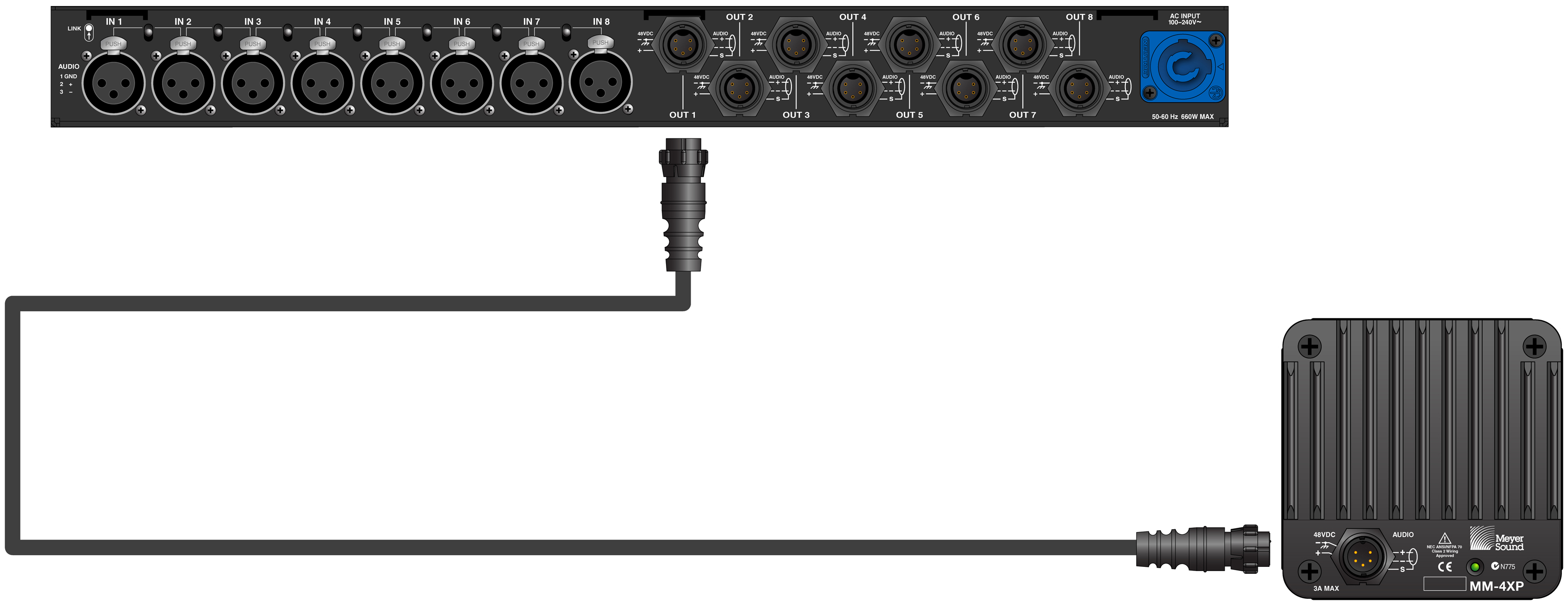
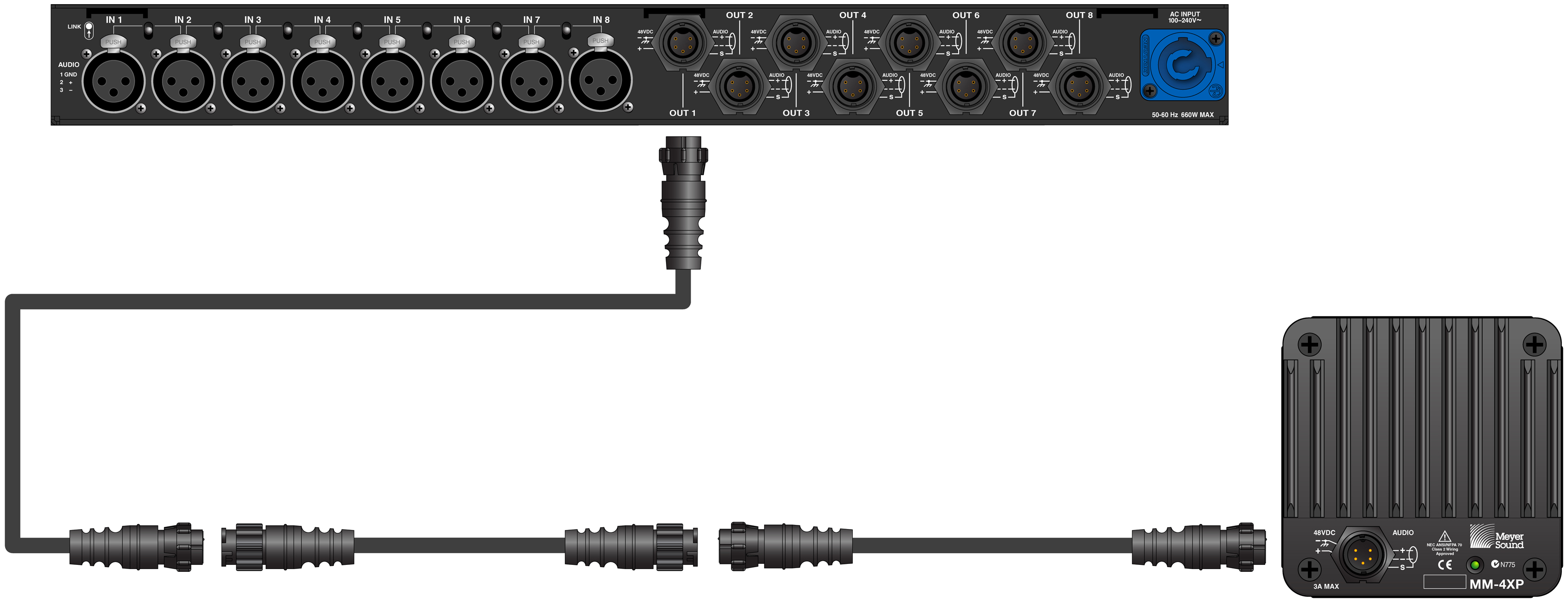
Connect the MM-4XP loudspeakers to the MPS channel outputs. Use a composite cable (such as Belden 1502) wired for both DC power and balanced audio and outfitted with the appropriate connector:
For an MPS-488HPP or MPS-482HP power supply, use an EN3 5-pin female to Phoenix 5-pin female cable.
For an MPS-488HPE power supply, use an EN3 5-pin female to EN3 5-pin male cable.
To join two cables, one with an EN3 5-pin male cable mount connector to one with an EN3 5-pin female cable mount connector, use an EN3 5-pin female-to-male cable coupler (PN 28.163.033.01).
Caution
Make sure the MM-4XP loudspeaker cables are wired correctly. For details on assembling loudspeaker cables, see Assembling Loudspeaker Cables.
Power on the MPS power supply and monitor the LEDs on the front panel to verify connections (for more information, see Voltage and Load Current LEDs.
Check the MM-4XP LEDs on the rear panel and verify they are green (ready to reproduce audio).
Enable output from the audio sources (from the mixer or processor) connected to the MPS power supply.
Mounting the MM-4XP
Important Safety Considerations
When installing Meyer Sound loudspeakers and subwoofers, the following precautions should always be observed:
All Meyer Sound products must be used in accordance with local, state, federal, and industry regulations. It is the owner’s and user’s responsibility to evaluate the reliability of any mounting and rigging method for their application. Mounting and rigging should only be carried out by experienced professionals.
Use mounting and rigging hardware that has been rated to meet or exceed the weight being hung.
Make sure to attach mounting hardware to the building's structural components (studs or joists), and not just to the wall surface. Verify that the building's structure and the anchors used for the installation will safely support the total weight of the mounted loudspeakers.
Use mounting hardware appropriate for the surface where the loudspeaker will be installed.
Make sure bolts and eyebolts are tightened securely. Meyer Sound recommends using Loctite® on eyebolt threads and safety cables.
Inspect mounting and rigging hardware regularly. Immediately replace any worn or damaged components.
Mounting the MM-4XP with the MUB-MM4XP U-bracket
With the MUB-MM-4XP U-bracket, you can mount the MM-4XP on almost any flat surface at adjustable angles.
Mount the MUB-MM-4XP U-bracket to the mounting surface using screws in the two holes in the back of the U-bracket. Use fastening hardware appropriate for the mounting surface.
Insert the MM-4XP into the U-bracket, seating its sides against the bracket’s attached neoprene strips. Align the loudspeaker’s screw inserts near the top of the U-bracket’s slots to allow for maximum tilting.
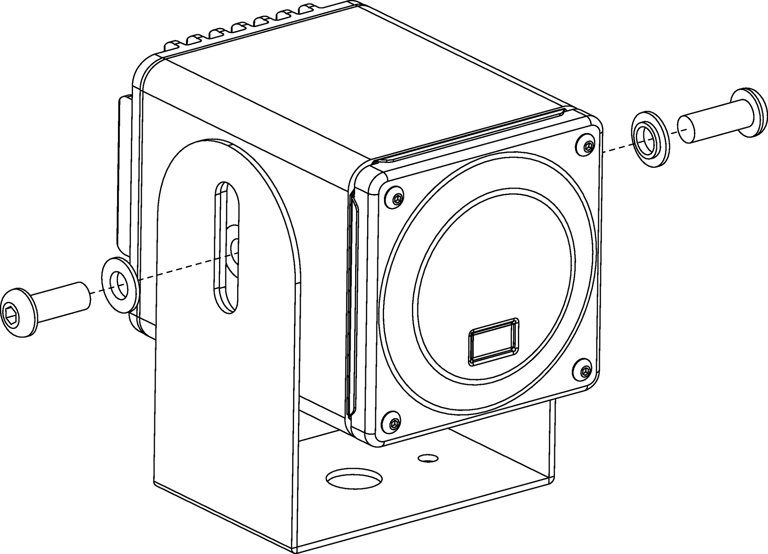
Secure the loudspeaker to the U-bracket using the two 3/8-inch-16 screws and two shoulder washers included with the MUB-MM-4XP. Place the shoulder washers between the screws and the outside of the U-bracket, with the shoulder oriented toward the loudspeaker. Do not yet tighten the U-bracket screws.

Caution
Make sure to use the shoulder washers. They insulate the MM-4XP from the U-bracket and mounting surface, eliminating grounding and differential problems.
Adjust the angle of the loudspeaker as desired.
Tighten the U-bracket screws to secure the MM-4XP.
System Design and Integration Tools
MAPP System Design Tool
The MAPP System Design Tool is a powerful, cross-platform application for accurately predicting the coverage pattern, frequency response, phase response, impulse response, and SPL capability of individual or arrayed Meyer Sound loudspeakers.

MAPP System Design Tool
Whether planning for fixed installations or for tours with multiple venues, use MAPP to accurately predict the appropriate loudspeaker deployment for each job, complete with coverage data, system delay and equalization settings, rigging information, and detailed design illustrations. MAPP’s accurate, high-resolution predictions ensure that systems will perform as intended, thereby eliminating unexpected coverage problems and minimizing onsite adjustments.
The key to the accuracy of MAPP’s predictions is MeyerSound’s exhaustive database of loudspeaker measurements. Performance predictions for each loudspeaker are based on 3-dimensional, 65,000+ 1/48th-octave-band measurements taken in the MeyerSound anechoic chamber. The extraordinary consistency between Meyer Sound loudspeakers guarantees that predictions from MAPP will closely match their actual performance.
MAPP software allows for configuration of MeyerSound loudspeaker systems and definition of the environment in which they operate, including air temperature, pressure, humidity, and the location of prediction surfaces. Importing both CAD (.DXF) and Sketchup (.SKP) files containing detailed venue information to act as an anchor model to the prediction surfaces and a visual aid to facilitate prediction data interpretation is also possible.
Tip
See meyersound.com for support and more information about MAPP.
MAPP Capabilities
With MAPP, you can:
Simulate different loudspeaker configurations to refine system designs and determine the best coverage for intended audience areas
Model loudspeaker interactions to locate constructive and destructive interferences so that loudspeakers can be re-aimed and repositioned as necessary
Place microphones anywhere in the Model View space and predict loudspeaker frequency response, phase response, and sound pressure levels at each microphone position
Determine delay settings for fill loudspeakers using the Inverse Fast Fourier Transform and phase response feature
Preview the results of signal processing to determine optimum settings for the best system response
Automatically calculate load information for arrays to determine necessary minimum rigging capacity, front-to-back weight distribution, and center of gravity location
Generate and export system images and system PDF reports for client presentations
Synchronize GALAXY processor output channel settings in real-time with virtual or real GALAXY units, allowing in-the-field changes to be predicted during system alignments
Galileo GALAXY Network Platform
The Galileo GALAXY Network Platform is a sophisticated loudspeaker management tool for controlling all MeyerSound speaker types. The GALAXY loudspeaker processor extends a high level of audio control in driving and aligning loudspeaker systems with multiple zones. It provides a powerful tool set for corrective equalization (EQ) and creative fine-tuning for a full range of applications from touring to cinema.
Users can readily program the GALAXY processor using Compass software running on a host computer or via the Compass Go application for the iPad. Connecting MAPP to the GALAXY processor will also allow the user to push output channel settings created in MAPP as a starting point. Compass Control Software includes custom-designed settings for each family of speakers, as well as to integrate families together. For example, the Product Integration feature matches the phase characteristics between Meyer speaker families to ensure the most coherent summation.
Processing tools for inputs and outputs include delay, parametric EQ and U-Shaping EQ. Output processing also includes polarity reversal, Low-Mid Beam Control (LMBC), atmospheric correction, and All Pass filters.
The built-in summing and delay matrices allow a user to easily assign gain and delay values, respectively, at each cross point. This capability greatly facilitates using one loudspeaker to satisfy multiple purposes.
Front panel controls let a user intuitively and quickly operate a GALAXY processor without a computer during live use.
The GALAXY 408, GALAXY 816 and GALAXY 816-AES3 processor versions have the same audio processing capability with different I/O. See www.meyersound.com to locate their datasheets for more information.
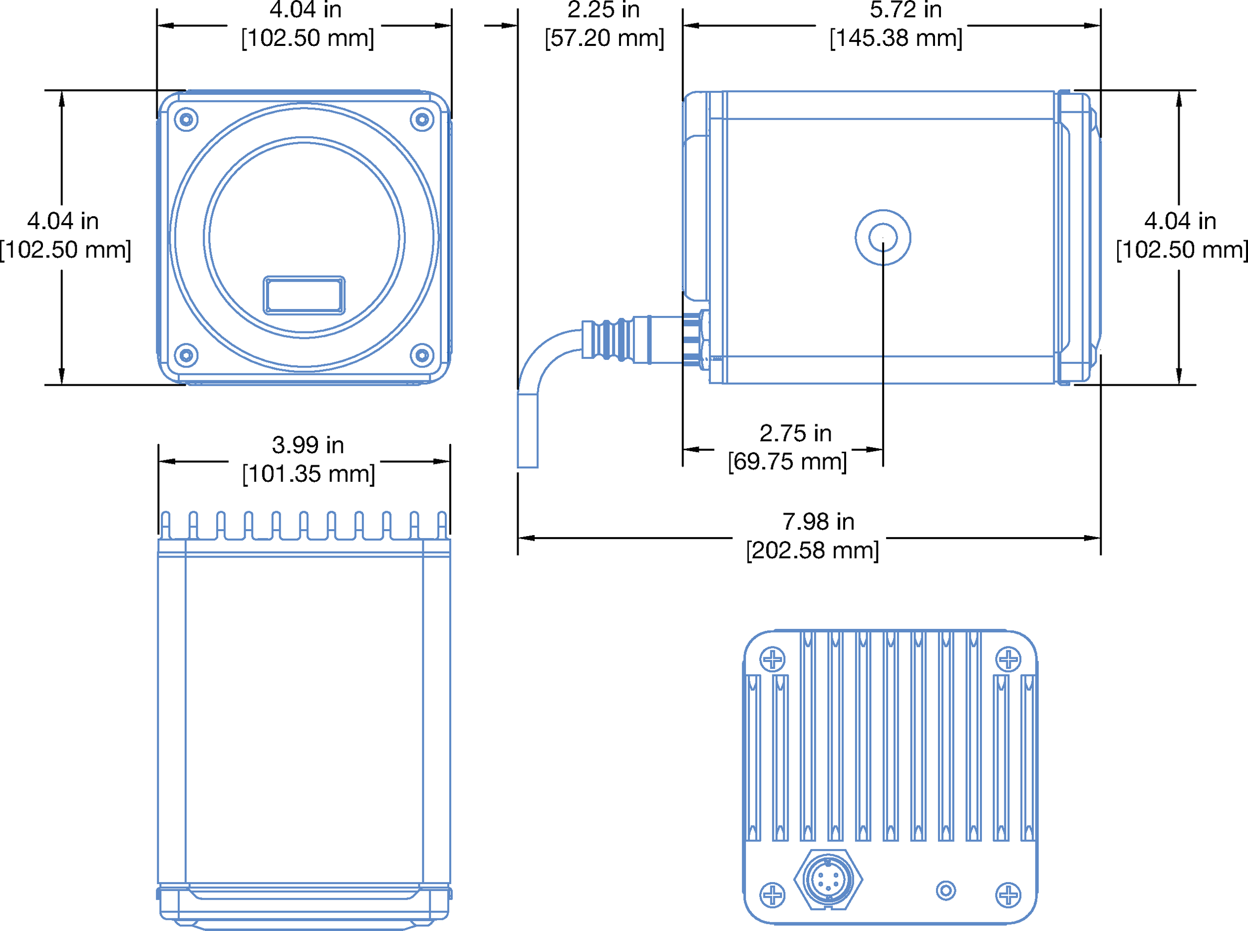
MM-4XP Loudspeaker Dimensions
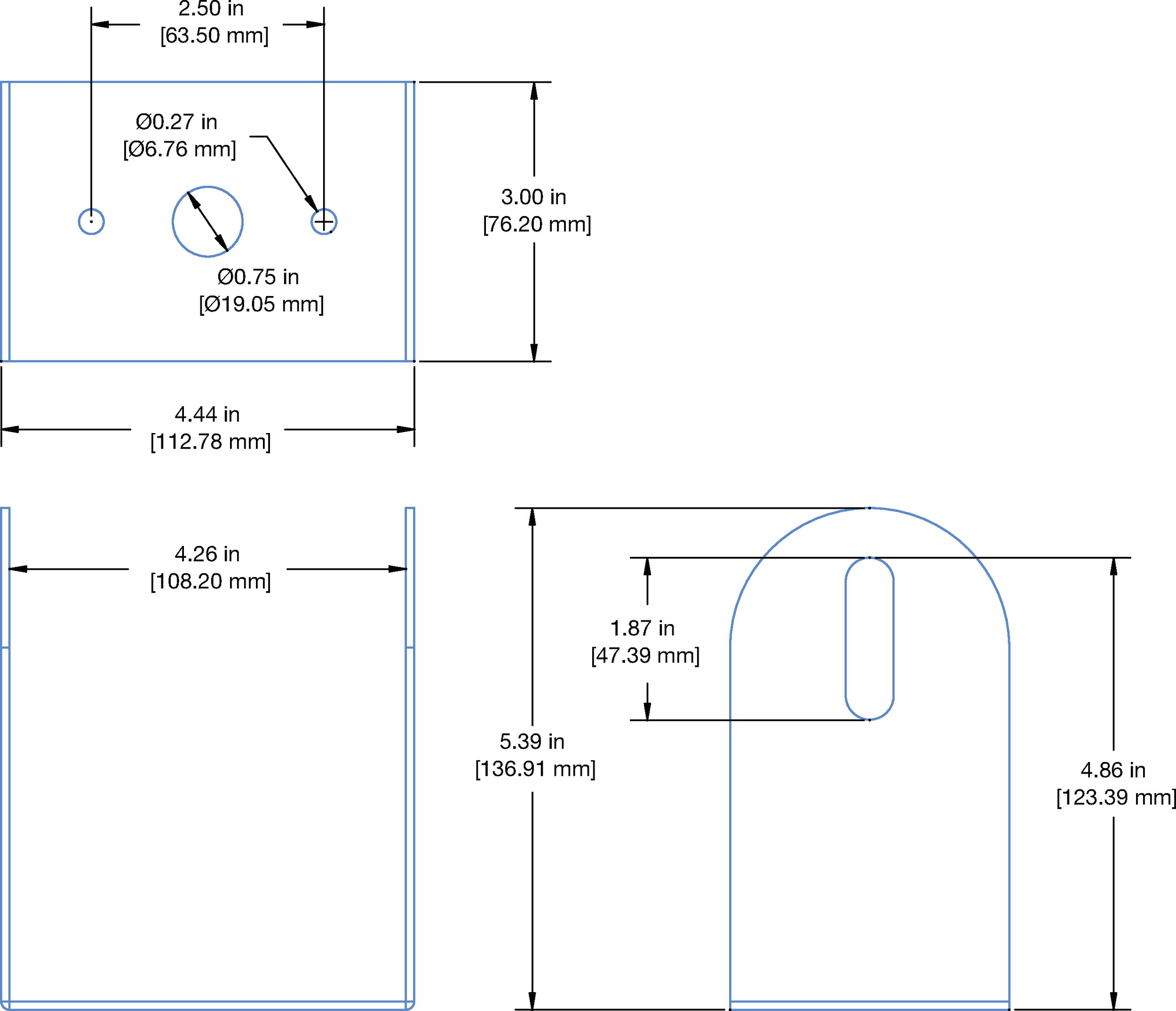
MUB-MM-4XP Dimensions
MM-4XP Accessories
Note
For information about the Meyer Sound Power Supply options, see meyersound.com/product/mps.
The following MM-4XP accessories are available from Meyer Sound.
Part Number | Accessory | Notes |
|---|---|---|
40.163.003.02 | MUB-MM-4XP Mounting Bracket (black) | Includes black mounting hardware |
40.163.003.04 | MUB-MM-4XP Mounting Bracket (white) | Includes clear mounting hardware |
MM-4XP Cable Connectors and Adapters
The following MM-4XP cable connectors and adapters are available from Meyer Sound.
Part Number | Connector/Adapter | Use |
|---|---|---|
484.053 | Phoenix 5-pin female cable mount connector | Connects to the MPS-488P channel output connector (a Phoenix 5-pin male connector). |
468.069 | EN3 5-pin female cable mount connector | Connects to the MM-4XP loudspeaker connector (an EN3 5-pin male panel mount connector). |
468.071 | EN3 5-pin male cable mount connector | Connects to the MPS-488E channel output connector (an EN3 5-pin female panel mount connector). |
468.072 | EN3 5-pin female inline cable adapter | Connects to an EN3 5-pin male cable mount connector. |
468.073 | EN3 5-pin male inline cable adapter | Connects to an EN3 5-pin female cable mount connector. |
28.163.033.01 | Cable coupler EN3 5-pin female-to-male | Joins two cables: one with an EN3 5-pin male cable mount connector to one with an EN3 5-pin female cable mount connector. |
MM-4XP cables
The following MM-4XP cables are available from Meyer Sound.
Note
All MM-4XP loudspeaker cables and bulk cable use Belden 1502R cable. Belden 1502 is a composite cable comprised of two 18 AWG wires for DC power, two 22 AWG wires for balanced audio, and one 24 AWG wire for audio shield.
Part Number | Cable | Color | Coating | Length |
|---|---|---|---|---|
524.014 | Bulk (no connectors) | Black | Regular | 500 ft spool |
524.015 | Bulk (no connectors) | White | Plenum | 500 ft spool |
28.163.009.01 | EN3 5-pin female to pigtail | Black | Regular | 10 ft |
28.163.009.11 | EN3 5-pin female to pigtail | White | Plenum | 10 ft |
28.163.009.21 | EN3 5-pin female to EN3 5-pin male | Black | Regular | 10 ft |
28.163.009.22 | 20 ft | |||
28.163.009.23 | 30 ft | |||
28.163.009.24 | 50 ft | |||
28.163.009.25 | 100 ft | |||
28.163.009.26 | 150 ft | |||
28.163.009.31 | EN3 5-pin female to EN3 5-pin male | White | Plenum | 10 ft |
28.163.009.32 | 20 ft | |||
28.163.009.33 | 30 ft | |||
28.163.009.34 | 50 ft | |||
28.163.009.35 | 100 ft | |||
28.163.009.36 | 150 ft | |||
28.163.033.01 | Cable coupler EN3 5-pin female-to-male (joins two cables: one with an EN3 5-pin male cable mount connector to one with an EN3 5-pin female cable mount connector) | |||
28.163.009.41 | EN3 5-pin female to Phoenix 5-pin female | Black | Regular | 10 ft |
28.163.009.42 | 20 ft | |||
28.163.009.43 | 30 ft | |||
28.163.009.44 | 50 ft | |||
28.163.009.45 | 100 ft | |||
28.163.009.46 | 150 ft | |||
28.163.009.51 | EN3 5-pin female to Phoenix 5-pin female | White | Plenum | 10 ft |
28.163.009.52 | 20 ft | |||
28.163.009.53 | 30 ft | |||
28.163.009.54 | 50 ft | |||
28.163.009.55 | 100 ft | |||
28.163.033.01 | 150 ft | |||
Assemble IntelligentDC loudspeaker cables
When wiring IntelligentDC loudspeaker cables, each pin in the cable must align correctly with the corresponding pin in the MPS channel output connector (see Channel Outputs). Ensure the 48 V DC from the MPS power supply connects directly (and only) to the 48 V DC pins on the loudspeaker connector, and that the polarity aligns (negative to negative, positive to positive) to prevent damage to the loudspeaker. In addition, verify the audio pin polarity, as reversals in audio signals can affect system performance.
Wire | Gauge | Signal |
|---|---|---|
Red | 18 AWG | DC power, positive (+) |
Black | 18 AWG | DC power, negative (–) |
White | 22 AWG | balanced audio, positive (+) |
Blue | 22 AWG | balanced audio, negative (–) |
Shield | 24 AWG | balanced audio, shield |
Assemble Phoenix-to-EN3 cables
When connecting loudspeakers equipped with EN3 connectors to power supplies equipped with Phoenix connectors, you'll need a Phoenix 5-pin female-to-EN3 5-pin female cable like the one shown below. The following procedure describes how to assemble this cable. If starting with an EN3-to-pigtail cable, skip steps 4–7 in this procedure.

Strip the cable jacket one (1) inch and then strip the black, red, blue, and white wires by 0.275 inch.

Warning
Do not tighten screws while the connector rests in a mating plug. Doing so will damage the contacts. During assembly, only hold the Phoenix connector externally in place.
With the connector oriented as shown below (lug screws up), insert the five exposed conductors into the five cable holes of a Phoenix 5-pin female cable mount connector. Use the following wiring scheme.

Secure the conductors by tightening the five screws in the Phoenix cable mount connector torqued to 0.5–0.6Nm (4.4–5.3In-Lbs).

On the other end of the cable, strip the outer cable jacket one (1) inch and then strip the black, red, blue, and white wires 0.275 inch.
Disassemble the EN3 5-pin female connector and feed the stripped cable through the boot, cable clamp housing, and coupling ring.

Solder the five exposed conductors to the five pins on the EN3 cord connector using the following wiring scheme.
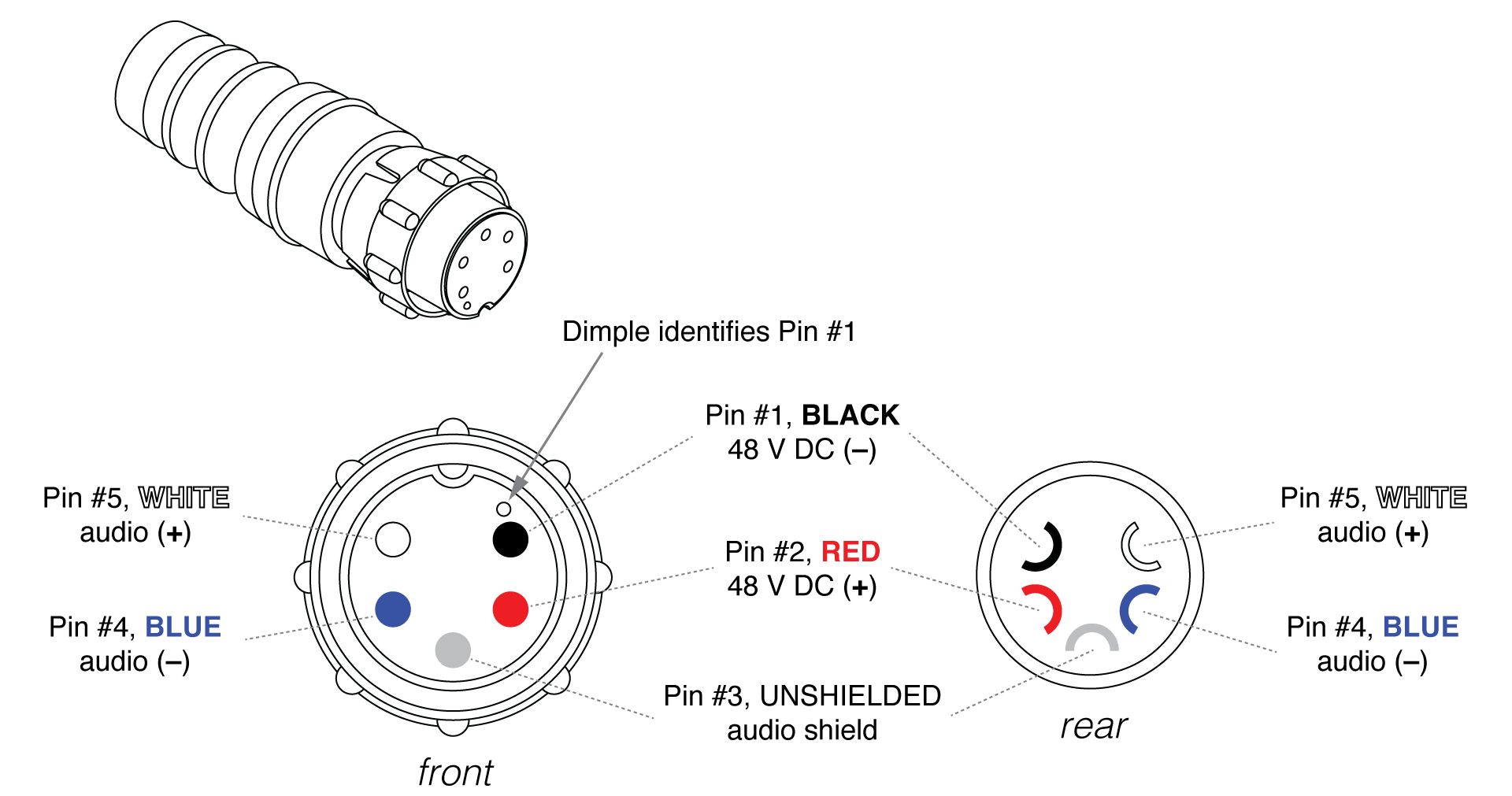
Reassemble the EN3 5-pin female connector:
Align the coupling ring’s side notches with the cord connector’s side notches and slide the coupling ring onto the cord connector.
Carefully insert the end of the cable clamp housing into the cord connector until it locks into place. Snap the cable clamps into their compartments in the cable clamp housing.
Slide the boot forward until it completely covers the cable clamp housing.
Using a continuity or impedance meter, verify that each pin on one connector connects to the corresponding pin on the other connector.
Assemble EN3-to-EN3 cables for legacy MPS power supplies
To connect an IntelligentDC loudspeaker to a legacy MPS power supply, you may need an EN3 5-pin female to EN3 5-pin male cable like the one shown below. The following procedure describes how to assemble this cable. If you start with an EN3-to-pigtail cable, you can disregard step 5 in the procedure.

Note
Cable mount connectors cannot connect to other cable mount connectors. Cable mount connectors can only connect to panel mount connectors (like those on the loudspeaker and legacy MPS power supplies) or inline connectors. To extend cables with EN3 connectors on both ends you can use an EN3 5-pin female-to-male cable coupler (PN 28.163.033.01).
Strip one end of the cable's outer shielding by one (1) inch and then strip the black, red, blue, and white wires by 0.275 inch.

Disassemble the EN3 5-pin male connector and feed the stripped cable through the boot, cable clamp housing, and coupling ring.
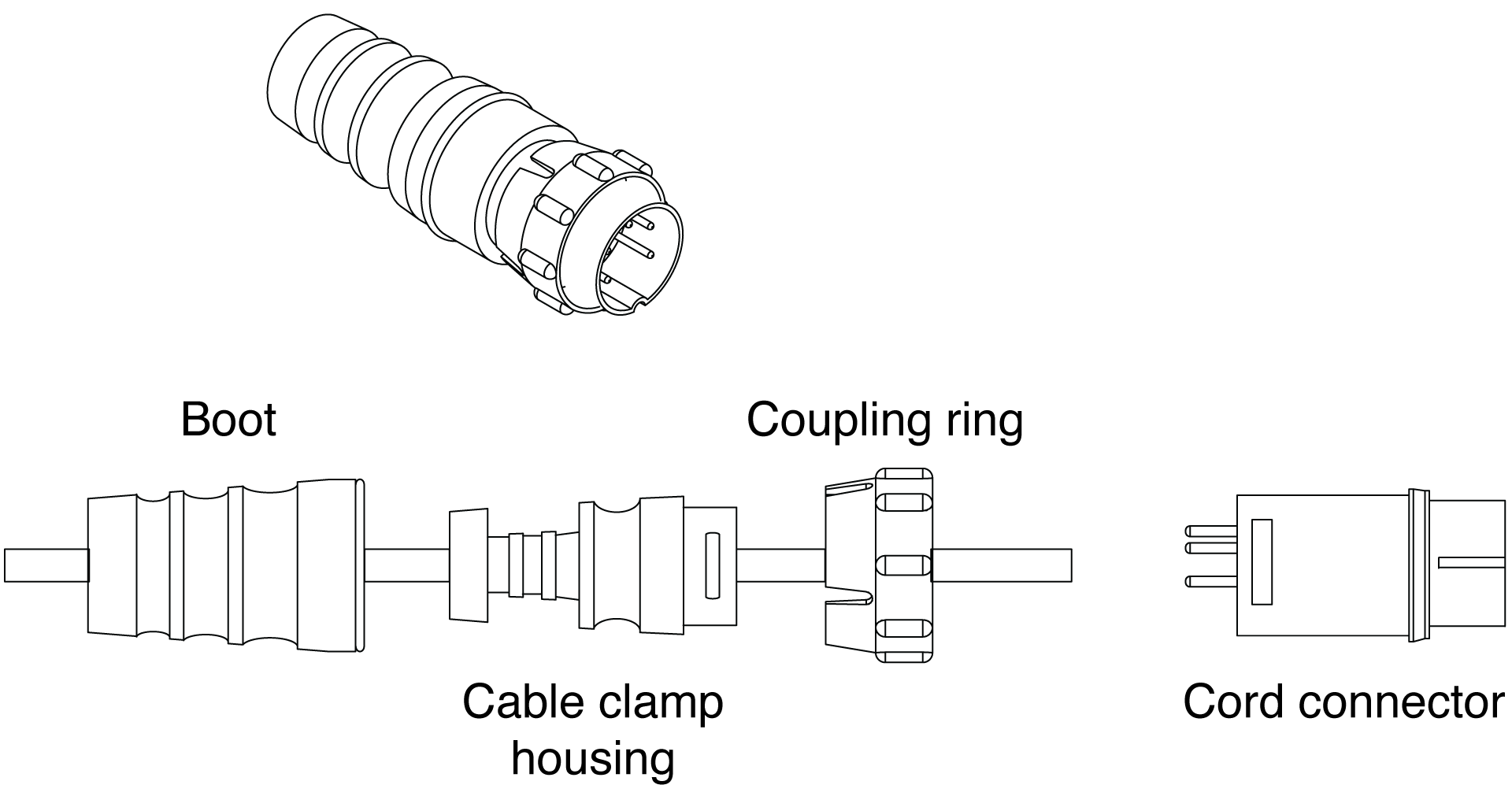
Solder the five exposed conductors to the five pins on the EN3 cord connector using the following wiring scheme.

Reassemble the EN3 5-pin male connector:
Align the coupling ring’s side notches with the cord connector’s side notches and slide the couple ring onto the cord connector.
Carefully insert the end of the cable clamp housing into the cord connector until it locks into place. Snap the cable clamps in the cable clamp housing into their compartments.
Slide the boot forward so it covers the cable clamp housing completely.
Repeat steps 1-4 to attach the EN3 5-pin female connector to the other end of the cable.

Pin Destinations for EN3 5-Pin Female Cable Mount Connector
Verify correct wiring polarity for both cable ends.

