Operating Instructions — Acheron 80 | 100 | LF
Screen Channel Loudspeakers
The Acheron Screen Channel Loudspeaker is available in two full-range models: the Acheron 100, with a 100-degree horizontal by 50-degree vertical horn, which is ideal for wide theatres; and the Acheron 80, with an 80-degree horizontal by 50-degree vertical horn, which is suitable for narrow theatres and re-recording, production, and post-production facilities.
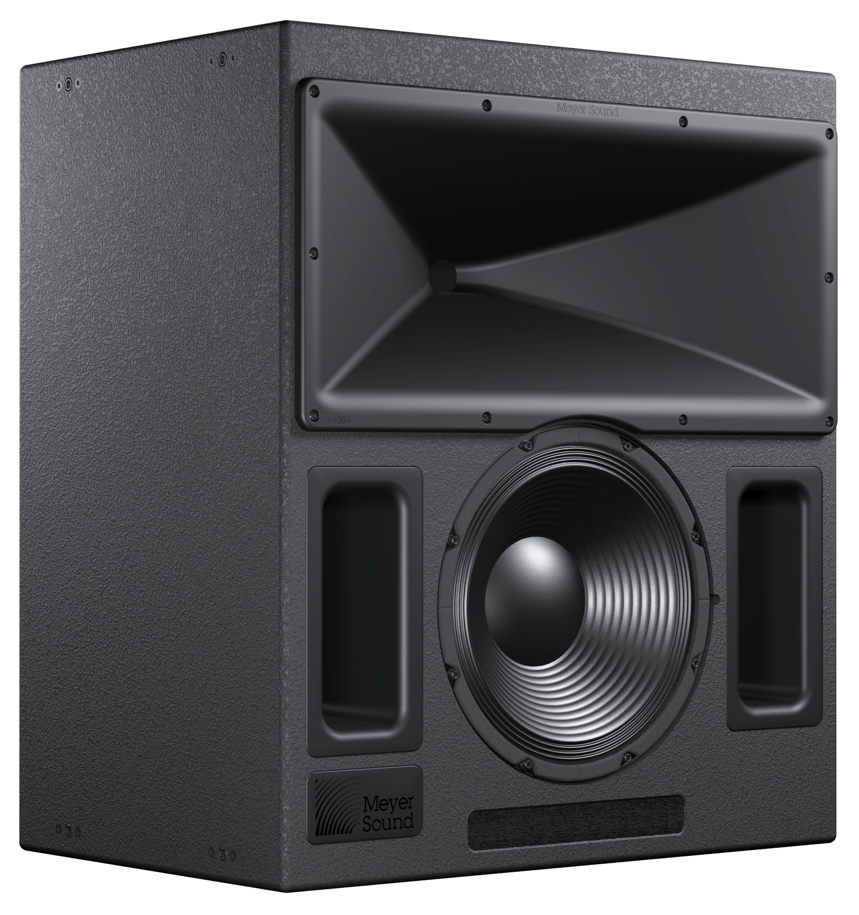 |
Acheron 100 Screen Channel Loudspeaker
The patented Acheron horn was specifically designed for cinema use and features a very soft roll-off outside the extremely well-behaved coverage angle. The horn is fixed within the enclosure to ensure an accurate acoustic crossover, phase response, and an incredibly consistent vertical pattern between the low and high frequencies. The Acheron’s 580 Hz crossover point places most of the dialog in the horn, which is ideal for cinema applications.
Boasting a frequency response of 38 Hz to 17 kHz at ±4 dB, as well as a generous peak output of 139 dB at 1 meter with very low distortion, the Acheron stands up to the most demanding of digital soundtracks, maintaining a wide dynamic range and full fidelity. Designed and manufactured at Meyer Sound's headquarters in Berkeley, California, the Acheron's drivers include one 15-inch low-frequency neodymium magnet cone driver and one high-frequency 4-inch diaphragm compression driver. The drivers yield uncompromising quality and full bandwidth, making the Acheron suitable for small and medium theatres, re-recording stages, and production and post-production facilities. When pairing an Acheron with an Acheron LF, the system offers enough headroom for large theatres.
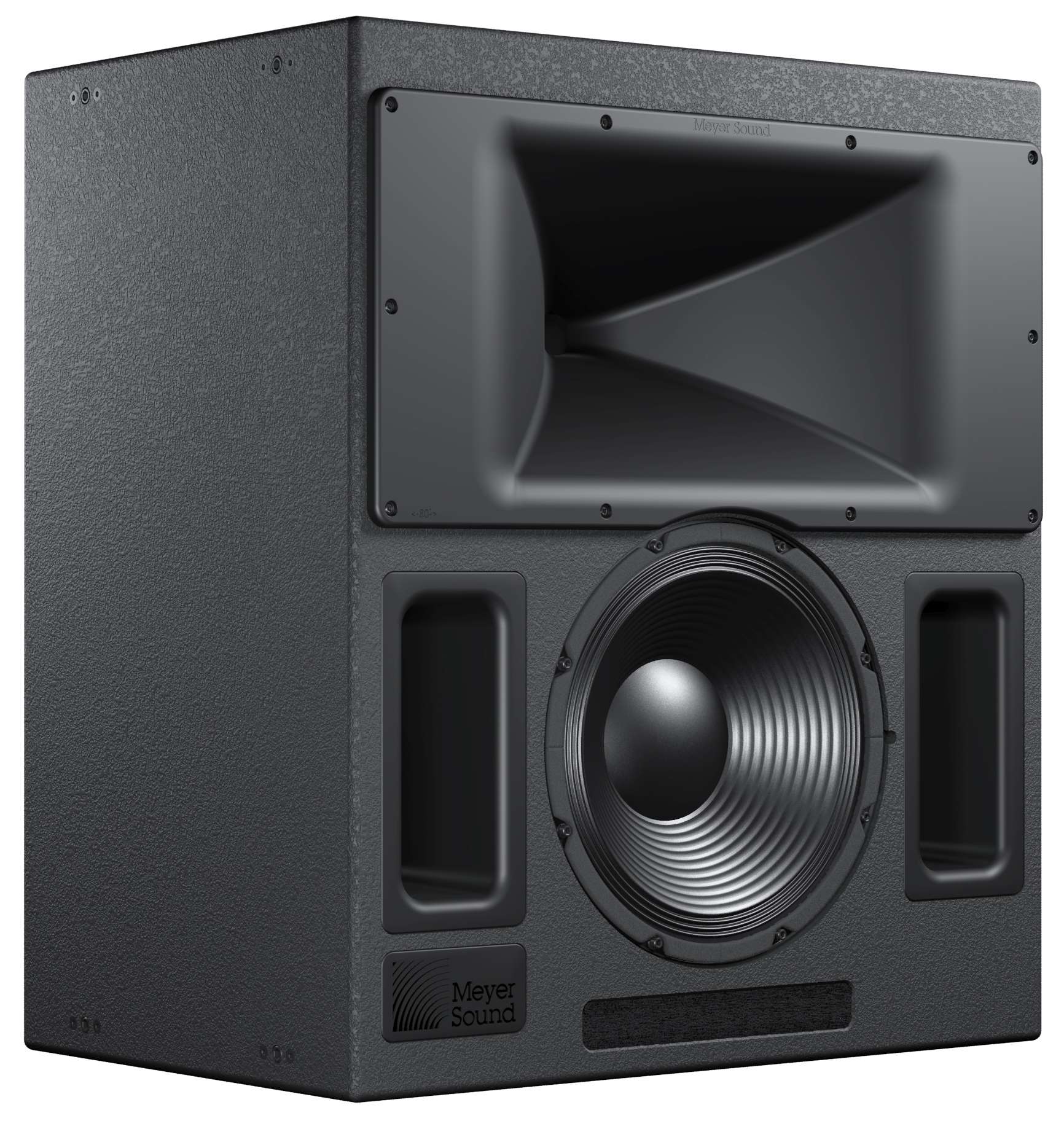 |
Acheron 80 Screen Channel Loudspeaker
The Acheron's sophisticated onboard amplification produces consistent and predictable results in any system design. The proprietary Meyer Sound power amplifier is a two-channel, class AB/H amplifier with complementary MOSFET output stages that yields a total output of 1685 W (3370 W peak). Built-in signal processing includes an electronic crossover and correction filters — to achieve a flat phase and frequency response — along with driver protection circuitry. The self-powered design not only ensures consistent results but also simplifies installation in both new and existing rooms.
The optional RMS™ remote monitoring system allows comprehensive monitoring of system parameters on a Windows®- based computer.
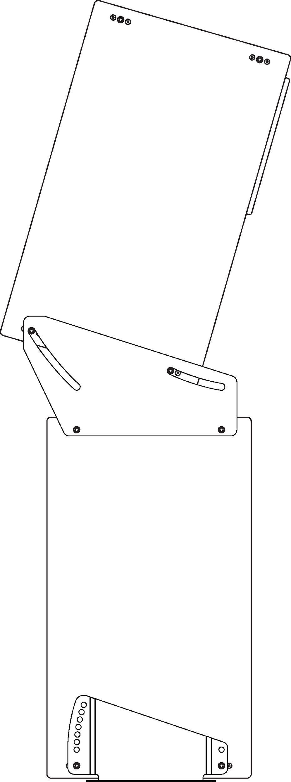
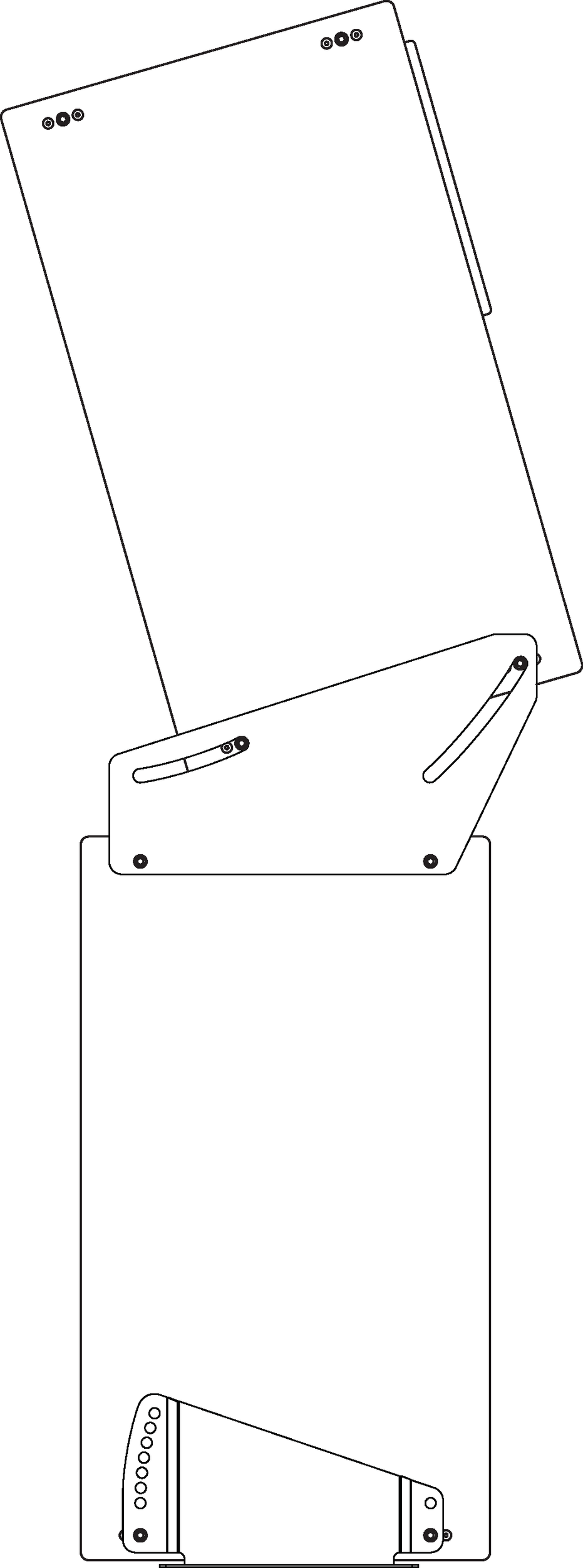
Strategically placed 3/8-inch threaded points on the side corners of the Acheron cabinet allow the unit to be secured to floors with uptilt or downtilt using the optional mounting brackets. The Acheron can also be mounted on top of the Acheron LF loudspeaker, with uptilt or downtilt, using the optional stacking brackets. Both brackets are available for purchase from Meyer Sound.
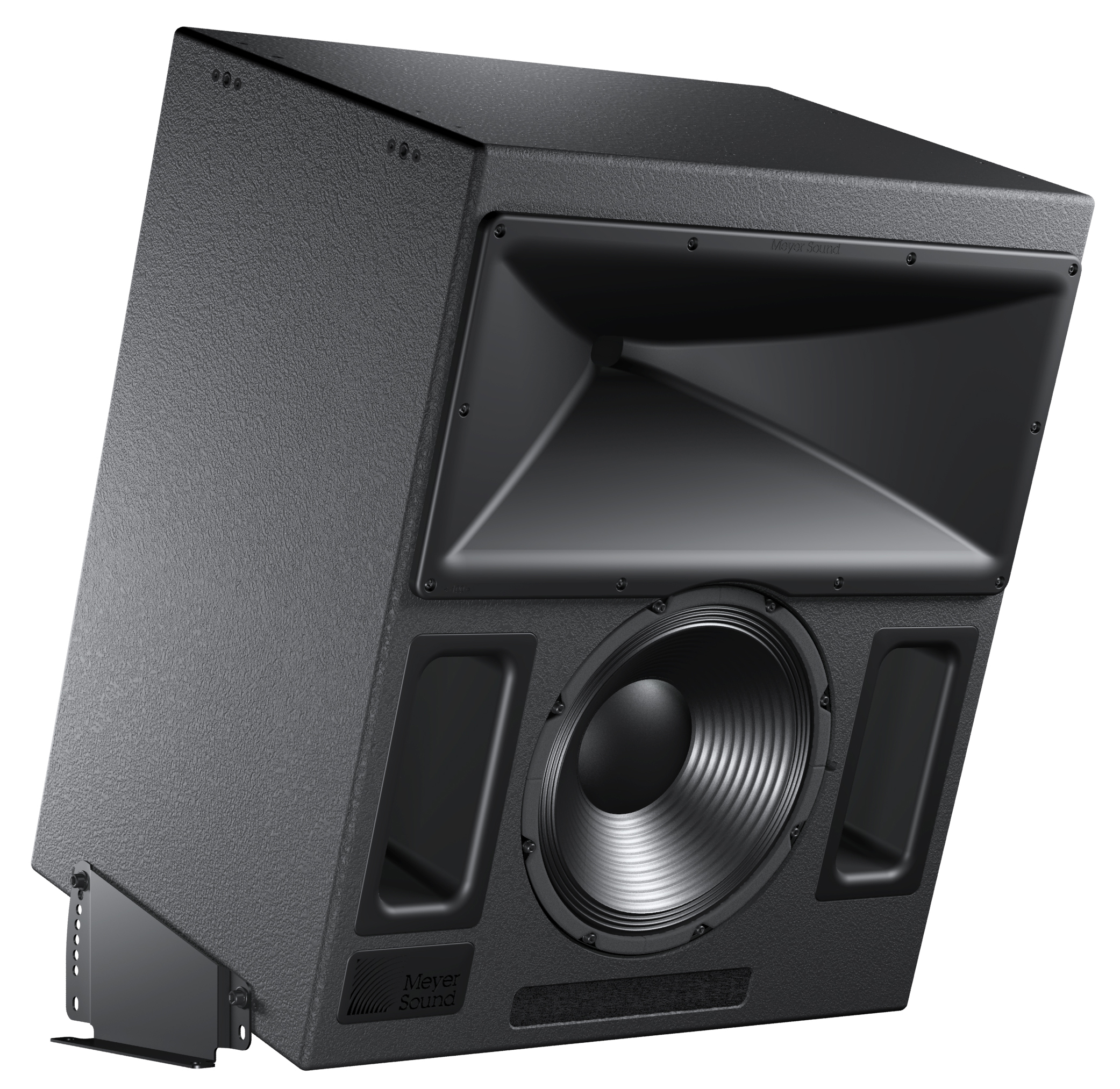 |
Acheron 100 with Optional Floor Mount Brackets, Front View
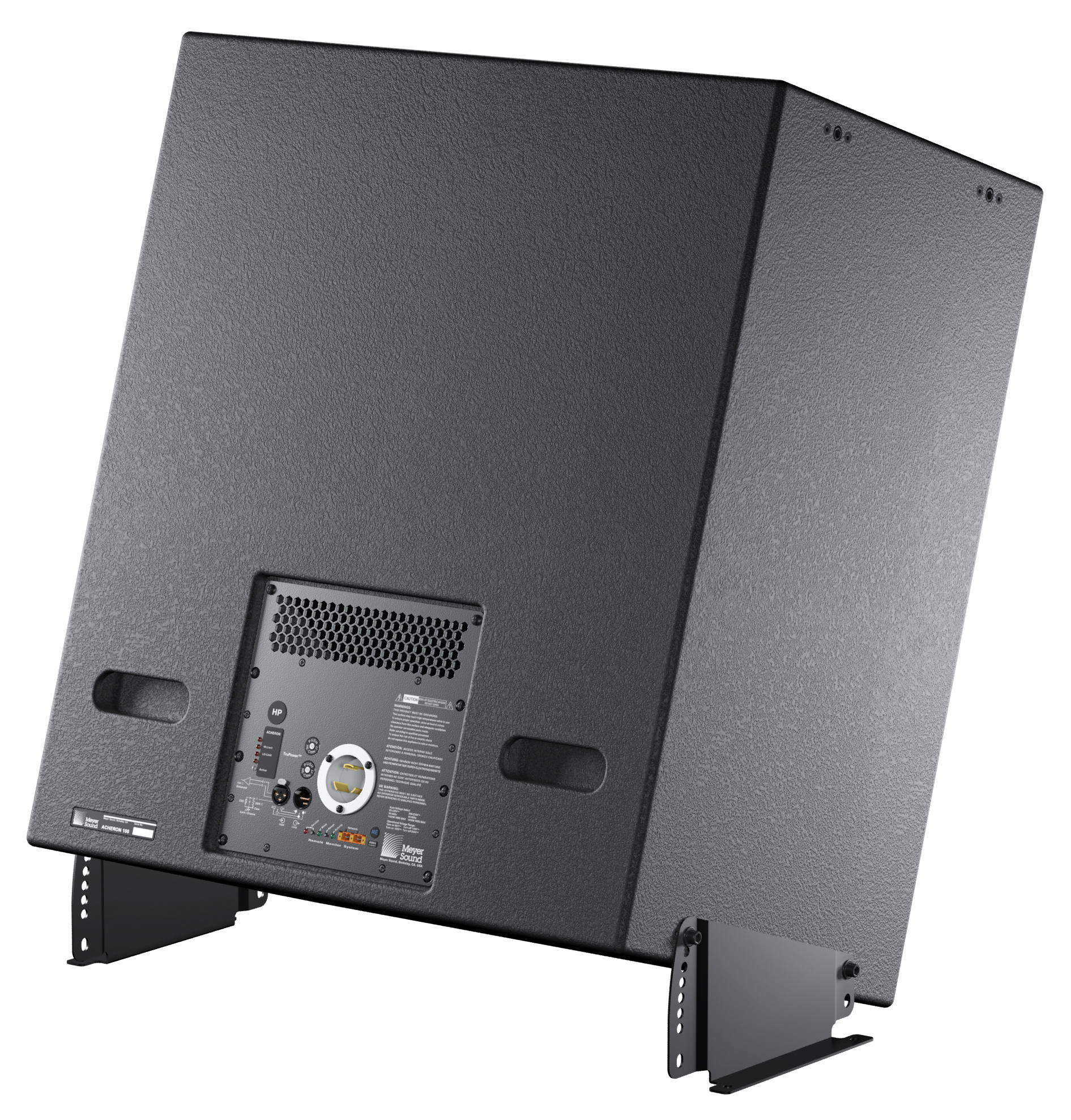 |
Acheron100 with Optional Floor Mount Brackets, Rear View
Acheron LF Loudspeaker
The AcheronLF loudspeaker can be paired with the Acheron80 or Acheron100 screen channel loudspeaker to deliver the low-frequency headroom required by larger theatres. The self-powered AcheronLF with dual 15-inch drivers boosts the headroom on the LCR channels by converting each Acheron loudspeaker to a system with three low-frequency drivers in an aligned column.
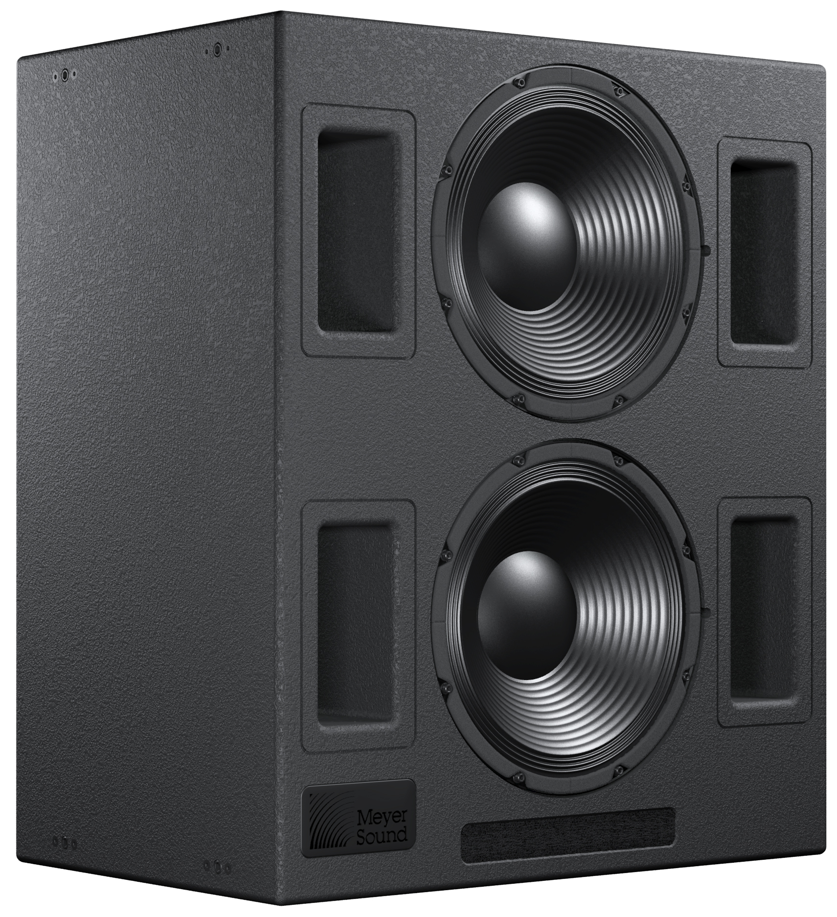 |
Acheron LF Screen Channel Loudspeaker
The unique multi-way, gradated design of the Acheron LF Screen Channel Loudspeaker offers smooth coverage and maximum low-frequency impact with all drivers active at the lowest frequencies and each rolling off, one at a time, via the integral active crossover. This technique eliminates interference between drivers that would otherwise occur at shorter wavelengths, enabling the system to maintain ideal polar, phase, and frequency responses throughout the low and low-mid operating ranges. As a result, the system can deliver the necessary power to fill a large theatre with rich, clean sound, thereby ensuring that the full intensity and nuance so carefully crafted into today’s movie soundtracks reach every listener without compromise.
The Acheron LF was designed exclusively for use with Acheron loudspeakers. The Acheron LF's 37 Hz to 370 Hz operating frequency range and 136 dB maximum peak SPL (at 1 meter) were carefully chosen to complement the Acheron. The Acheron LF also features the same high-power 15-inch cone driver used in the low-frequency section of the Acheron. Engineered to deliver optimum performance, the high-excursion, back-vented drivers include 4-inch voice coils and are housed in a tuned, vented enclosure that shares the same rectangular footprint as the Acheron.
The Acheron LF is powered by an onboard two-channel class AB/H amplifier with complementary MOSFET output stages. Total output power is 2250 W (4500 W peak) and provides the system with enough headroom to easily accommodate the extreme demands of digital soundtracks.
The optional RMS remote monitoring system allows comprehensive monitoring of system parameters on a Windows-based computer.
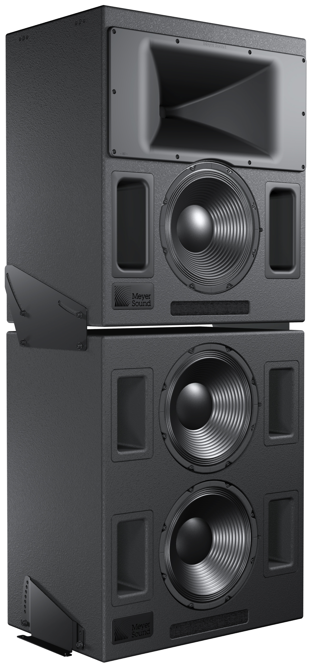 |
Acheron LF with Acheron 80
Strategically placed 3/8-inch threaded points on the side corners of the Acheron LF cabinet allow the unit to be secured to floors with the optional mounting brackets. An Acheron can be mounted on top of the Acheron LF with uptilt or downtilt using the optional stacking brackets.
Power Requirements
The Acheron loudspeaker combines advanced loudspeaker technology with equally advanced power capabilities. Understanding power distribution, voltage and current requirements, and electrical safety guidelines is critical to the safe operation of the Acheron.
AC Connector
The Acheron AC connector supplies AC power to the unit and is located on its rear user panel. The Acheron can be equipped with one of the following AC connectors:
IEC 309 male inlet connector

NEMA L6-20 (twistlock) male inlet

The Acheron requires a grounded outlet. To operate safely and effectively, it is extremely important that the entire system be properly grounded.
If you replace the included AC power cable, make sure to use a cable that is wired correctly and equipped with the appropriate power plug (on the other end) for the area in which you will operate the unit.
AC Power Cable with Edison Adapter
The Acheron can be powered from a standard three-prong Edison outlet with an L6-20 to Edison adapter (available for purchase from Meyer Sound; PN 27.033.024.03).
 |
L6-20 to Edison AC Power Cable Adapter
AC Connector Wiring
When wiring international or special-purpose AC power cables and connectors, use the following wiring scheme:
 |
AC Cable Wiring Scheme
Connect the blue wire to the black terminal, or the terminal marked with an N.
Connect the brown wire to the red terminal, or the terminal marked with an L.
Connect the yellow and green wire to the green (or green and yellow) terminal, or the terminal marked with an E.
Caution
When creating AC power cables and distribution systems, it is important to preserve AC line polarity and connect the earth ground on both ends of the cable. The Acheron requires a grounded connection. Always use a grounded outlet and plug. It is extremely important that the system be properly grounded to operate safely and properly. Do not ground-lift the AC cable.
AC Power Distribution
All components in an audio system (self-powered loudspeakers, processors, etc.) must be properly connected to an AC power distribution system, to ensure that AC line polarity is preserved and that all grounding points are connected to a single node or common point using the same cable gauge as the neutral and line cables.
Note
Improper grounding of connections between loudspeakers and the rest of the audio system may produce noise or hum, or cause serious damage to the input and output stages of the system’s electronic components.
Caution
Before applying AC power to any Meyer Sound self-powered loudspeaker, make sure that the voltage potential difference between the neutral and earth-ground lines is less than 5 V AC.
The figure below illustrates a basic three-phase AC distribution system with the loudspeaker load distributed across the three phases. All loudspeakers are connected to common neutral and earth-ground lines.
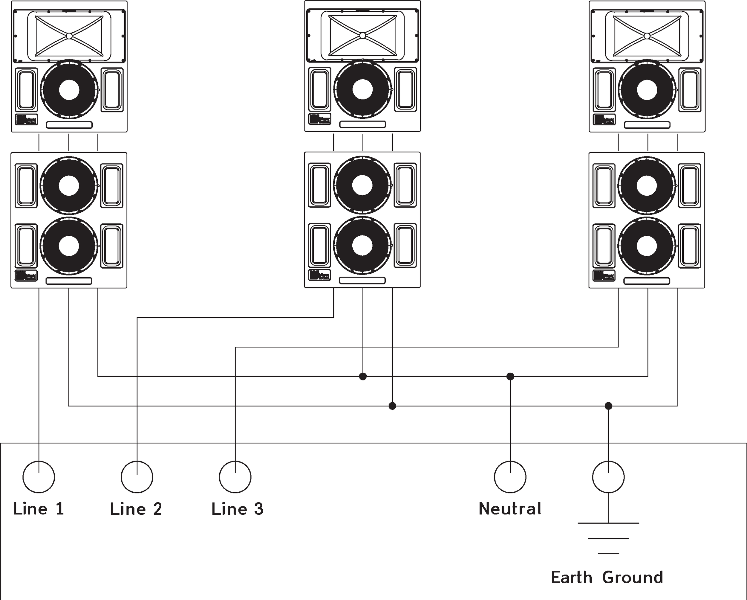
AC Power Distribution System
Acheron voltage requirements
The Acheron operates safely and continuously when the AC voltage stays within 85–134 V AC and 165–264 V AC at 50 or 60 Hz. The loudspeaker allows any combination of voltage to GND (neutral-line-ground or line-line-ground).
If the voltage drops below 85 V (brownout), the Acheron uses stored power to continue operating temporarily; the loudspeaker will shut down if the voltage does not rise above the low boundary before the stored power is used.
If the voltage rises above 275 V, the power supply could become damaged.
Caution
The power source for the Acheron should always operate within the required voltage range, at least a few volts from the upper and lower ranges. This ensures that AC voltage variations from the service entry—or peak voltage drops due to cable runs—will not cause the loudspeaker’s amplifier to cycle on and off or cause damage to the power supply.
Tip
Since the Acheron does not require a dedicated neutral line, and it can tolerate elevated voltages from the ground line, it can be connected to line-line terminals in 120 V, 3-phase Wye systems. This results in 208 V AC between lines (nominal) and therefore draws less current than when using 120 V AC (line-neutral). Make sure that the voltage remains within the Acheron’s recommended operating windows (85–134 V AC and 165–264 V AC). The ground line must always be used for safety reasons and the line-to-ground voltage should never exceed 250 V AC (typically 120 V AC from line-to-ground).
Acheron Current Requirements
The current draw for the Acheron is dynamic and fluctuates as operating levels change. Since different cables and circuit breakers heat up at varying rates, it is important to understand the following types of current ratings and how they affect circuit breaker and cable specifications.
Idle Current — The maximum rms current during idle periods.
Maximum Long-Term Continuous Current — The maximum rms current during a period of at least 10 seconds. The Maximum Long-Term Continuous Current is used to calculate temperature increases for cables, to ensure that cable sizes and gauges conform to electrical code standards. The current rating is also used as a rating for slow-reacting thermal breakers.
Burst Current — The maximum rms current during a period of around one second. The Burst Current is used as a rating for magnetic breakers. It is also used for calculating the peak voltage drop in long AC cable runs according to the following formula:
V pk (drop) = I pk x R (cable total)
Maximum Instantaneous Peak Current — A rating for magnetic breakers.
Inrush Current — The spike of initial current encountered when powering on.
You can use the following tables as guidelines for selecting cable gauge and circuit breaker ratings for the system’s operating voltage.
Current Draw | 115 V AC | 230 V AC | 100 V AC |
|---|---|---|---|
Idle Current | 0.71 A rms | 0.38 A rms | 0.79 A rms |
Maximum Long-Term Continuous Current | 5.8 A rms | 2.8 A rms | 6.3 A rms |
Burst Current | 6.4 A rms | 3.2 A rms | 7.2 A rms |
Maximum Instantaneous Peak Current | 26 A peak | 14 A peak | 28 A peak |
Inrush Current | 7 A peak | 7 A peak | 10 A peak |
Current Draw | 115 V AC | 230 V AC | 100 V AC |
|---|---|---|---|
Idle Current | 0.64 A rms | 0.32 A rms | 0.85 A rms |
Maximum Long-Term Continuous Current | 8.8 A rms | 4.4 A rms | 10.0 A rms |
Burst Current | 19 A rms | 9.5 A rms | 22 A rms |
Maximum Instantaneous Peak Current | The USW-112P compact narrow subwoofer provides big bass sound for very tight spaces. Its compact rectangular enclosure and slanted connector panel enable flushmounting of the cabinet against wall surfaces, reducing required installation depth to 12 inches, including connectors. | 20 A peak | 45 A peak |
Inrush Current | 7 A peak | 7 A peak | 10 A peak |
The minimum electrical service amperage required by an Acheron loudspeaker system is the sum of the Maximum Long-Term Continuous Current for each loudspeaker. An additional 30 percent above the minimum amperage is recommended to prevent peak voltage drops at the service entry.
Note
For best performance, the AC cable voltage drop should not exceed 10 V, or 10 percent at 115 V and 5 percent at 230 V. Make sure that even with AC voltage drops that the AC voltage always remains within the operating windows.
Powering Up the Acheron
When AC power is applied to the Acheron its Intelligent AC™ power supply automatically selects the correct operating voltage, allowing it to be used internationally without manually setting voltage switches. In addition, Intelligent AC suppresses high-voltage transients up to several kilovolts, filters common mode and differential mode radio frequencies (EMI), and sustains operation temporarily during low-voltage periods.
When powering up the Acheron, the following startup events take place over several seconds.
Audio output is muted.
Voltage is detected and the power supply mode is automatically adjusted as necessary.
The primary ultra-low-noise fan turns on.
The power supply ramps up.
The green Active LED on the user panel lights up, indicating the loudspeaker is ready to output audio.
Caution
If the Active LED does not light up, or the Acheron does not output audio after ten seconds, remove AC power immediately and verify that the voltage is within the required range. If the problem persists, contact Meyer Sound Technical Support.
If either of the loudspeaker’s circuit breakers trip (the white center buttons disengage), do NOT reset and reapply power. Disconnect the AC power and contact Meyer Sound Service Department for instructions on how to proceed.
Electrical safety guidelines
Pay close attention to these important electrical and safety guidelines.
The Acheron requires a grounded outlet. Always use a grounded outlet and plug.
 |
Make sure the AC power cable for the loudspeaker has the appropriate power plug (on the other end) for the area in which you will operate the loudspeaker.
Do not operate the unit if the power cable is frayed or broken.
Keep all liquids away from the Acheron to avoid hazards from electrical shock.
Amplification and Audio
The Acheron drivers are powered by a two-channel proprietary Meyer Sound amplifier with MOSFET output stages. The audio signal is processed with an electronic crossover, correction filters for phase and frequency response, and driver protection circuitry. Each channel has peak and rms limiters that prevent driver over-excursion and regulate the temperature of the voice coil.
The Acheron rear panel has an audio Input and Loop output connector, Limit LEDs, and an optional RMS module for connecting to the RMS remote monitoring system (see The RMS Remote Monitoring System).
Audio Connectors
The Acheron and Acheron LF include female XLR Input and male XLR Loop output connectors.
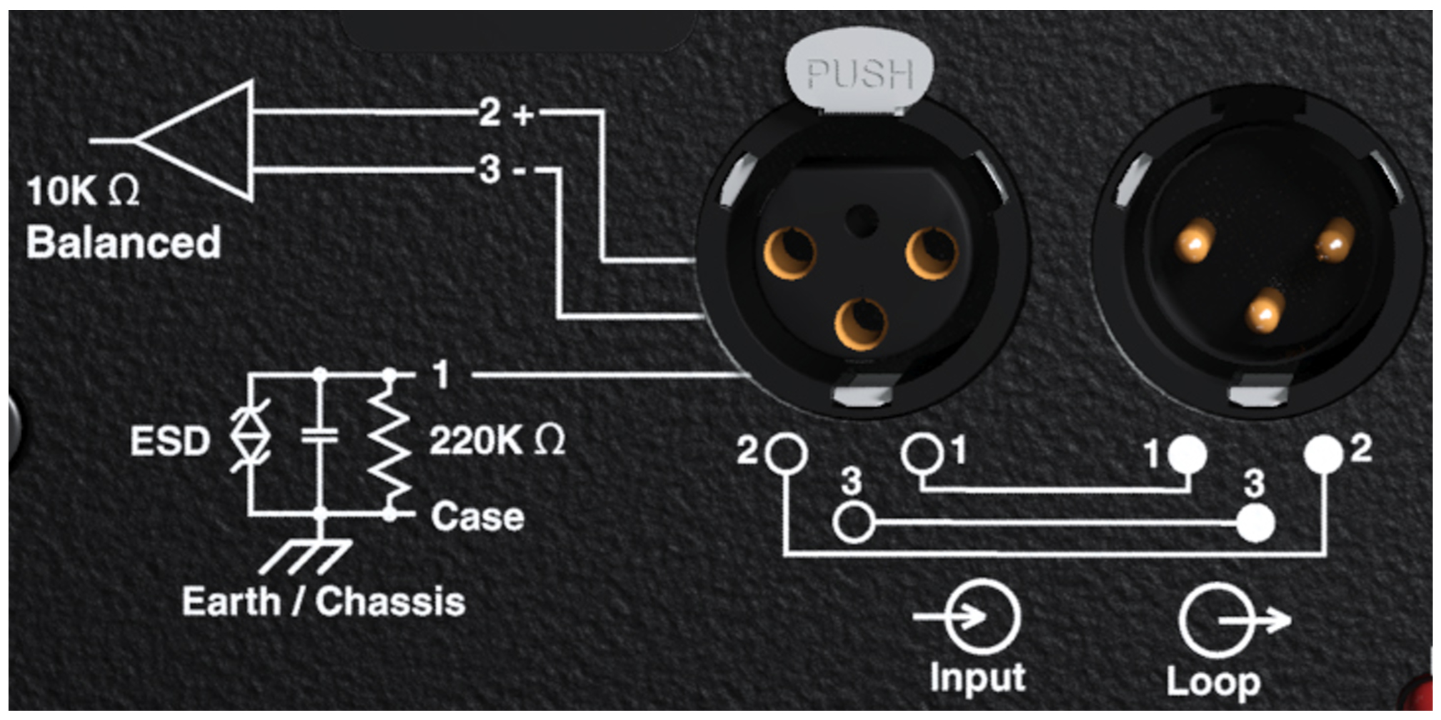 |
Acheron Audio Connectors, Input and Loop Output
Input Connector
The female XLR Input connector accepts a balanced audio signal with an input impedance of 10 kOhm. The connector uses the following wiring:
Pin 1 — 220 kOhm to chassis and earth ground (ESD clamped)
Pin 2 — Signal (+)
Pin 3 — Signal (–)
Case — Earth (AC) ground and chassis
Pins 2 and 3 carry the input as a differential signal. Pin 1 is connected to earth through a 220 kOhm, 1000 pF, 15 V clamped network. This circuitry provides virtual ground lift for audio frequencies while allowing unwanted signals to bleed to ground. Make sure to use standard, balanced XLR audio cables with all three pins connected on both ends.
Telescopic grounding is not recommended, and shorting an input connector pin to the case may cause a ground loop, resulting in hum.
Tip
If unwanted noise or hiss is produced by the loudspeaker, disconnect its input cable. If the noise stops, there is most likely nothing wrong with the loudspeaker. To locate the source of the noise, check the audio cable, source audio, and AC power.
Loop output connector
The male XLR Loop output connector allows Acheron and Acheron LF loudspeakers to be looped from a single audio source. For applications that require multiple Acherons and Acheron LFs, connect the Loop output of the first unit to the Input of the second, and so forth.
Note
The order in which loudspeakers are connected when looping audio signals is unimportant. The Loop connector is wired in parallel to the Input connector and transmits the unbuffered source signal even when the Acheron is powered off.
To avoid distortion when looping multiple Acherons, make sure the source device can drive the total load impedance of the looped loudspeakers. In addition, the source device must be capable of delivering approximately 20 dBV (10 V rms into 600 ohms) to yield the maximum peak SPL over the entire operating bandwidth of the loudspeakers. Most professional audio equipment can transmit these source levels.
To calculate the load impedance for the looped loudspeakers, divide 10 kOhms (the input impedance for a single Acheron) by the number of looped loudspeakers. For example, the load impedance for 10 Acheron loudspeakers is 1000 ohms (10 kOhms / 10). To drive this number of looped loudspeakers, the source device should have an output impedance of 100 ohms or less. This same rule applies when looping Acheron loudspeakers with other self-powered Meyer Sound loudspeakers and subwoofers.
Note
Most source devices are capable of driving loads no smaller than 10 times their output impedance.
Caution
Make sure that all cabling for looped loudspeakers is wired correctly (Pin 1 to Pin 1, Pin 2 to Pin 2, and so forth) to prevent the polarity from being reversed. If one or more loudspeakers in a system have reversed polarity, frequency response and coverage will be significantly degraded.
Limiting
Acheron loudspeakers employ Meyer Sound’s advanced TruPower® limiting. Conventional limiters assume a constant loudspeaker impedance and set the limiting threshold by measuring voltage alone. This method is inaccurate because loudspeaker impedances change as frequency content in the source material changes, and as thermal values for the loudspeaker’s voice coil and magnet vary. Consequently, conventional limiters often begin limiting prematurely, which reduces system headroom and dynamic range.
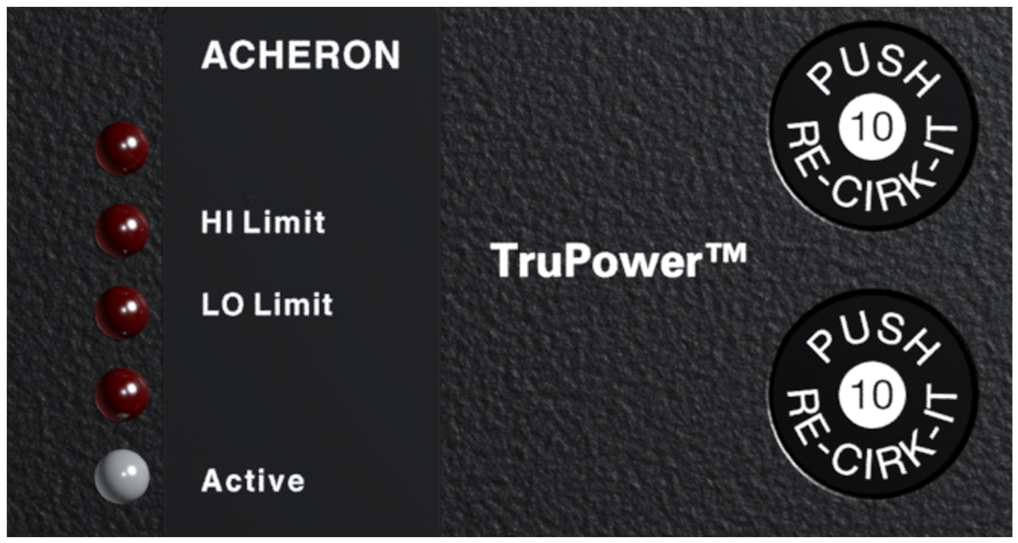 |
Acheron Limit LEDs
In contrast, TruPower limiting anticipates varying loud- speaker impedances by measuring both current and voltage to compute the actual power dissipation in the voice coil.
This improves performance, both before and during limiting, by allowing the driver to produce the maximum SPL across its entire frequency range. TruPower limiting also eliminates power compression at high levels over lengthy periods, which helps regulate voice coil temperatures, thereby extending the life of the driver.
Note
Since TruPower limiting only reduces signal levels to keep voice coil temperatures under a safe margin, signal peaks remain unaffected.
Limiting LEDs
Behavior for the Acheron Limit LEDs is described below:
The low- and high-frequency drivers for the Acheron 80 and Acheron 100 are powered by separate amplifier channels, each with their own limiter. Limiting activity is indicated with a High Limit LED for the high-frequency channel, and a Low Limit LED for the low-frequency channel.
The two low-frequency drivers for the Acheron LF are powered by separate amplifier channels that are routed to a single limiter. When a safe power level is exceeded in either channel, limiting is engaged for both channels and the Low Limit LED lights.
When engaged, the limiters not only protect the drivers but also prevent signal peaks from causing excessive distortion in the amplifier channels, thereby preserving headroom and maintaining smooth frequency responses at high levels.
When levels return to normal, below the limiter thresholds, limiting ceases.
The Acheron performs within its acoustical specifications at normal temperatures when the Limit LEDs are unlit, or if the LEDs are lit for two seconds or less and then turn off for at least one second. If the LEDs remain lit for longer than three seconds, the loudspeaker enters hard limiting where:
Increases to the input level have no effect.
Distortion increases due to clipping and nonlinear driver operation.
The drivers are subjected to excessive heat and excursion, which will compromise their life span and may eventually lead to damage over time.
Caution
The Limit LEDs indicate when a safe, optimum level is exceeded. If the Acheron 80s or Acheron 100s in a system begin to limit before reaching the required SPL, consider adding Acheron LFs to the system. For more information, see Integrating Acheron LF Loudspeakers
Note
Acheron loudspeakers use optical limiters that add no noise and have no effect on the signal when the limiters are not engaged and the Limit LEDs are not lit.
Amplifier Cooling System
The Acheron uses a forced-air cooling system with two fans (one variable-speed, ultra-low-noise primary fan and one reserve fan) to prevent the amplifier module from overheating. The fans draw air in through ducts on the front of the cabinet, over the heat sink, and out the rear of the cabinet. Because dust does not accumulate in the amplifier circuitry, its life span is increased significantly.
 |
Airflow for the Acheron
When the Acheron heat sink temperature is below 42° C, the variable-speed primary fan runs continuously at its slowest speed with an inaudible operating noise. The primary fan increases speed when the heat sink temperature reaches 42° C; the primary reaches full speed at 62° C and is barely audible near the cabinet, even without an audio signal. If the heat sink temperature reaches 74° C, the reserve fan turns on. The reserve fan turns on if:
The primary fan has failed (check status immediately)
High source levels are encountered for extended periods
Dust has accumulated along the cooling path
The reserve fan turns off when the heat sink temperature lowers to 68° C.
Note
In the unlikely event that the reserve fan does not keep the Acheron heat sink temperature below 85° C, the unit automatically shuts down until AC power is removed and reapplied. If the Acheron shuts down again after cooling and re- applying AC power, contact Meyer Sound for repair information.
Dust and the Amplifier Module
Operating the Acheron in dusty environments, or for prolonged, intensive periods, may cause dust to accumulate along its airflow path, thereby preventing normal cooling. Under these circumstances, it may be necessary to periodically remove the air intake foam and use compressed to air to clear the dust from the foam and air ducts.
In addition, if the amplifier gets unusually hot, you should remove the amplifier module and use compressed air to clear any dust from its heat sink.
Caution
Make sure to unplug the AC power from the Acheron before cleaning its amplifier.
To keep the Acheron from getting too hot, allow for proper ventilation, 3–4 inches, behind the loudspeaker.
Integrating Acheron LF Loudspeakers
To meet the SPL and low-frequency headroom requirements of large rooms, the Acheron 100 or Acheron 80 can be daisy-chained with the Acheron LF loudspeaker, creating a system with three low-frequency drivers and one high-frequency driver. Adding an Acheron LF yields approximately a 10 dB boost in the low-frequency range, depending on loading conditions and room acoustics.
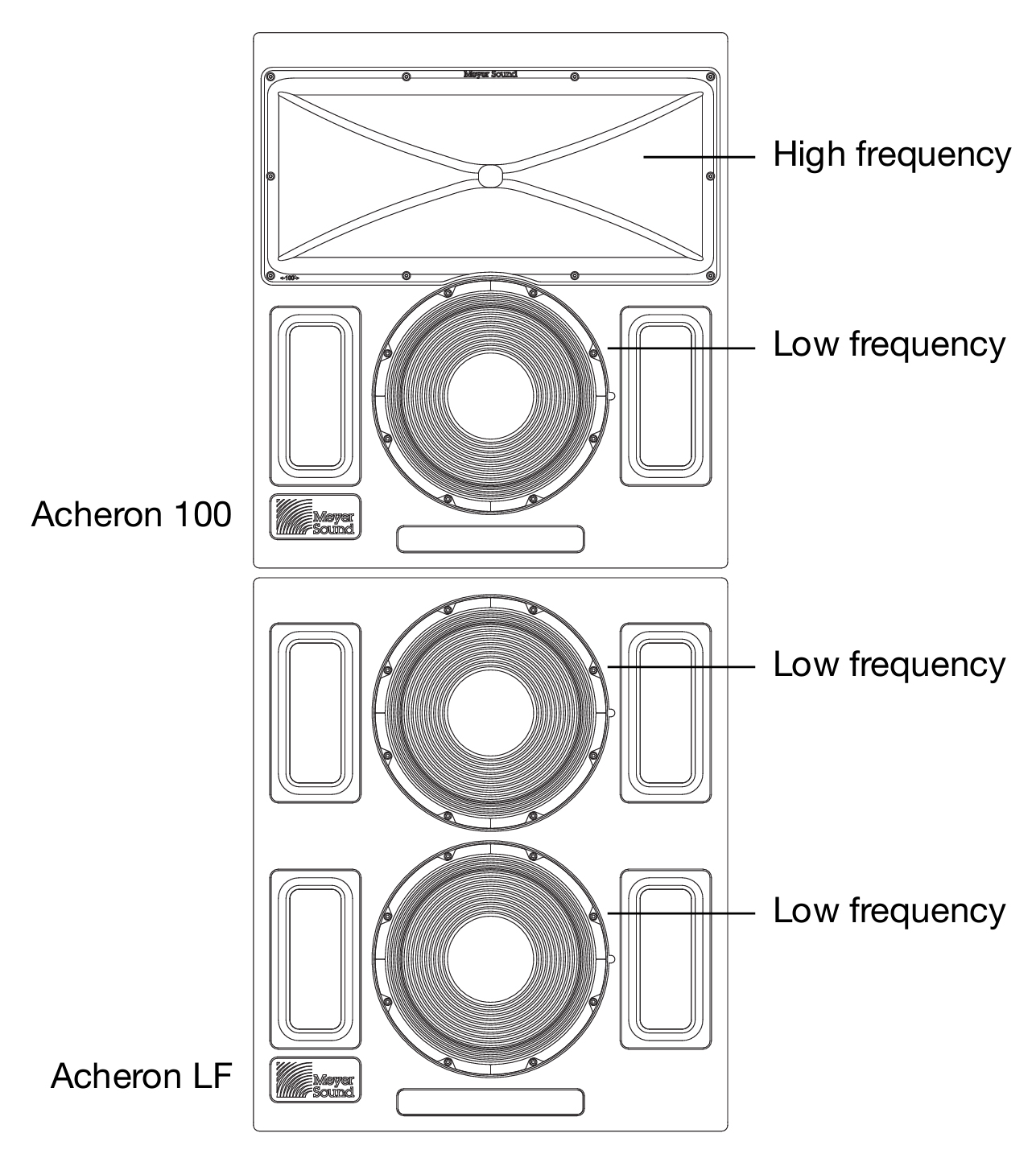 |
Acheron 100 with Acheron LF
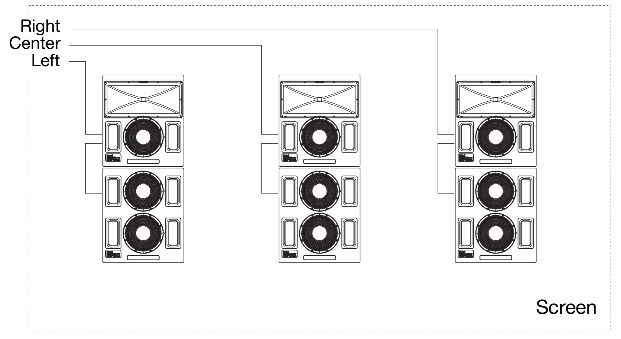 |
Acheron LCR System with Acheron LFs
The Acheron LF has been carefully designed so that its frequency and phase responses complement the Acheron. The Acheron LF has the same low-end frequency response as the Acheron (38 Hz) and rolls off at 320 Hz to avoid any interference in the crossover region of the Acheron.
At 38 Hz to 150 Hz, the low-frequency driver in the Acheron 80 or Acheron 100 and the two low-frequency drivers in the Acheron LF are all active. At 150 Hz, the bottom Acheron LF low-frequency driver rolls off.
At 150 Hz to 300 Hz, two low-frequency drivers are active: one in the Acheron 80 or Acheron 100 and the top Acheron LF driver. At 300 Hz, the top Acheron LF low-frequency driver rolls off.
At 300 Hz to 580 Hz, only the Acheron 80 or Acheron 100 low-frequency driver is active, which enables a smooth crossover to the high-frequency driver.
This unique multi-way, gradated design offers smooth coverage and maximum low-frequency impact with all drivers active at the lowest frequencies and each rolling off, one at a time, via the internal active crossover. This technique eliminates interference between drivers that would otherwise occur at shorter wavelengths, enabling the system to maintain ideal polar, phase, and frequency responses throughout the low and low-mid operating ranges. As a result, the system can deliver the necessary power to completely fill a large theatre.
Achieving a Flat Frequency Response with an Acheron / Acheron LF Stack
When the Acheron and Acheron LF are daisy-chained (using the Loop output connector on the user panel) an approximate boost of 10 dB at 110 Hz results, depending on the loading conditions and room acoustics. To achieve a flat frequency response in this configuration, a single parametric filter with the following characteristics can be applied to the signal:
Filter type | Parametric |
Frequency | 110 Hz |
Bandwidth | 2 (Q = 0.6667) |
Dimensions | –10 dB |
The Acheron LF has been carefully designed so that its frequency and phase responses complement the Acheron. The Acheron LF has the same low-end frequency response
Caution
When daisy-chaining Acherons and Acheron LFs, make sure the audio cables are wired correctly to avoid polarity reversals.
Using Digital Signal Processors and Crossovers with Acheron Systems
ACOUSTICAL
If a digital signal processor is used to drive an Acheron LCR system, the Acherons and Acheron LFs should be driven from the same processor to keep their delay times the same. Otherwise, a phase shift between the loudspeakers may be encountered. In addition, you should verify the delay time between channels: some digital signal processors may incur channel-to-channel delays when the processor is near maximum throughput, which becomes more likely as the number of filters in use by the processor increases.
In no case should a filter higher than the 2nd order be used on source signals. The additional phase shift introduced by these filters deteriorates the impulse response, and the higher roll-off does not improve crossover interaction.
If loudspeakers will be driven directly from a digital signal processor, make sure the signal is sufficient to drive the total load impedance of the connected loudspeakers. For more information, see Loop output connector.
Strategically placed 3/8-inch threaded points on the side corners of the Acheron cabinet allow the unit to be secured to floors with uptilt or downtilt using the optional mounting brackets. The Acheron can also be mounted on top of the Acheron LF loudspeaker, also with uptilt or downtilt, using the optional stacking brackets. Both brackets are available for purchase from Meyer Sound.
Mounting
Strategically placed 3/8-inch threaded points on the side corners of the Acheron cabinet allow the unit to be secured to floors with uptilt or downtilt using the optional mounting brackets. The Acheron can also be mounted on top of the AcheronLF loudspeaker, also with uptilt or downtilt, using the optional stacking brackets. Both brackets are available for purchase from Meyer Sound.
Important Safety Considerations
When installing Meyer Sound loudspeakers and subwoofers, the following precautions should always be observed:
All Meyer Sound products must be used in accordance with local, state, federal, and industry regulations. It is the owner’s and user’s responsibility to evaluate the reliability of any mounting and rigging method for their application. Mounting and rigging should only be carried out by experienced professionals.
Use mounting and rigging hardware that has been rated to meet or exceed the weight being hung.
Make sure to attach mounting hardware to the building's structural components (studs or joists), and not just to the wall surface. Verify that the building's structure and the anchors used for the installation will safely support the total weight of the mounted loudspeakers.
Use mounting hardware appropriate for the surface where the loudspeaker will be installed.
Make sure bolts and eyebolts are tightened securely. Meyer Sound recommends using Loctite® on eyebolt threads and safety cables.
Inspect mounting and rigging hardware regularly. Immediately replace any worn or damaged components.
Acheron and Acheron LF side screws
The Acheron and Acheron LF ship with four 3/8-16 x 1.5- inch screws installed on each loudspeaker side (eight total). These screws and threaded points are used to secure the floor mount and stacking brackets to the loudspeakers.
Caution
If the Acheron side screws are removed to install the brackets, make sure to always reinstall the screws, and tighten them securely. If the side screws are not present when using the loudspeakers, air leakage will result, which will adversely affect frequency response.
Acheron Floor Mount Brackets
The Acheron floor mount brackets secure Acheron loudspeakers to floors with downtilt and uptilt angles of 0–18 degrees (in 3-degree increments). The floor mount
brackets should also be used with Acheron LF loudspeakers when stacking an Acheron on top of the Acheron LF.
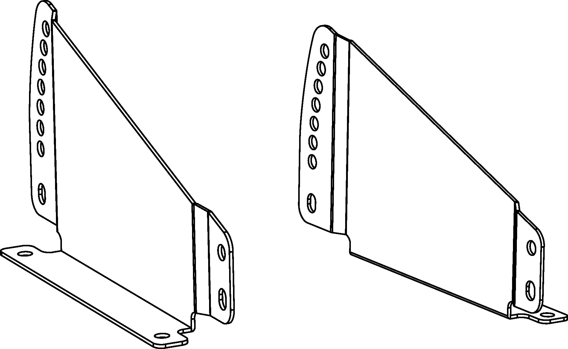 |
Acheron Floor Mount Brackets
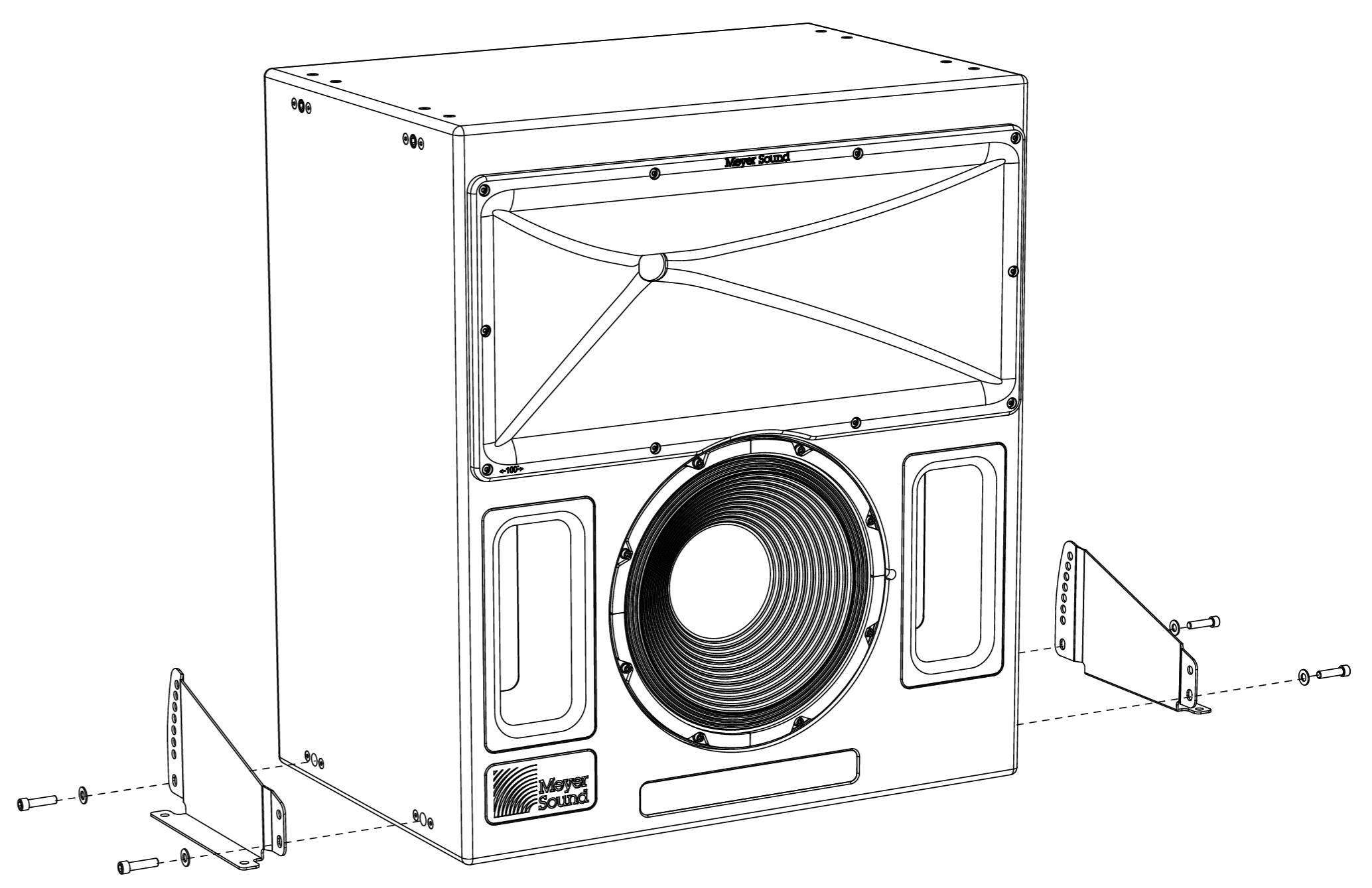 |
Acheron with Floor Mount Brackets
Acheron Floor Mount Bracket Kit Contents
The Acheron floor mount kit (PN 40.188.026.01) includes the following parts.
Part | Part number | Quantity |
|---|---|---|
Acheron floor mount bracket (left) | 64.188.042.01 | 1 |
Acheron floor mount bracket (right) | 64.188.043.01 | 1 |
Flat washers | 113.509 | 4 |
Note
The 3/8-16 x 1.5-inch screws required for securing the floor mount brackets to the Acheron are shipped with the loudspeaker installed in the two bottom screw holes on each side (four total).
Floor Mounting Acherons and Acheron LFs
Remove the two 3/8-16 x 1.5-inch screws at the bottom of each loudspeaker side (four total).
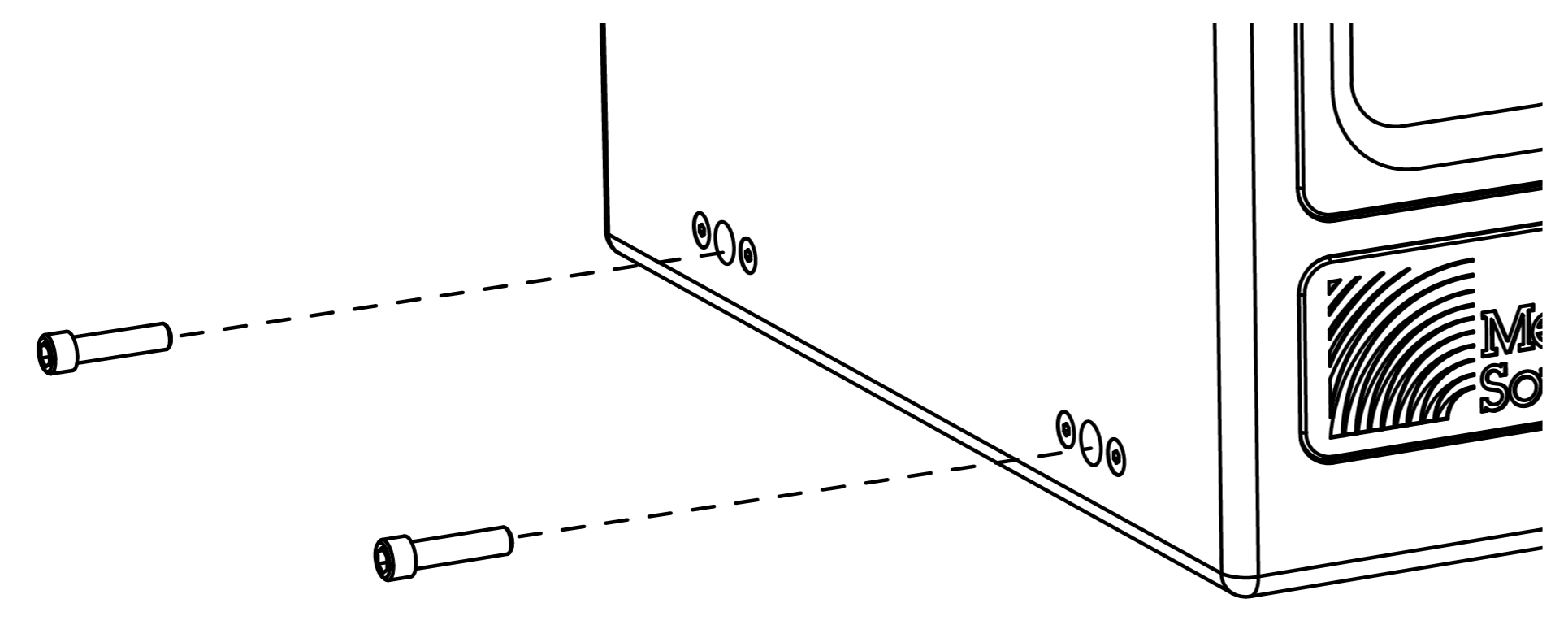
Secure the left bracket to the left side of the loudspeaker with two of the removed screws and two of the included flat washers.
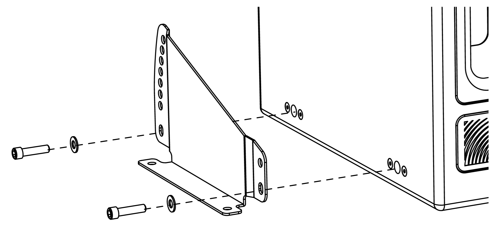
To mount the loudspeaker at 0 degrees with no downtilt or uptilt, use the bottom bracket holes.
To mount the loudspeaker with a downtilt, orient the bracket with the large end toward the rear of the loudspeaker. For available downtilt angles, see Floor Mount Downtilt Angles.
To mount the loudspeaker with uptilt, orient the bracket with the large end toward the front of the loudspeaker. For available uptilt angles, see Floor Mount Uptilt Angles.
Repeat the previous step with the right bracket and the remaining two screws and washers.
Secure the brackets to the floor with fasteners (not included) appropriate for the floor surface.
Floor Mounting Acherons with Downtilt and Uptilt
The Acheron floor mount brackets can mount loudspeakers with a downtilt or uptilt. Available angles are 3-18 degrees in 3-degree increments. The direction in which the brackets are oriented determines whether the loudspeaker can be mounted with downtilt or uptilt.
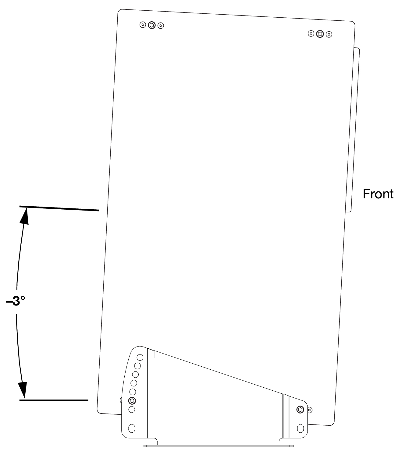 |
Acheron Floor Mounted with 3-Degree Downtilt
Caution
When using the floor mount brackets with an AcheronLF that will also have an Acheron stacked on top of it, mount the AcheronLF at 0 degrees using the bottom bracket holes.
Floor Mount Downtilt Angles
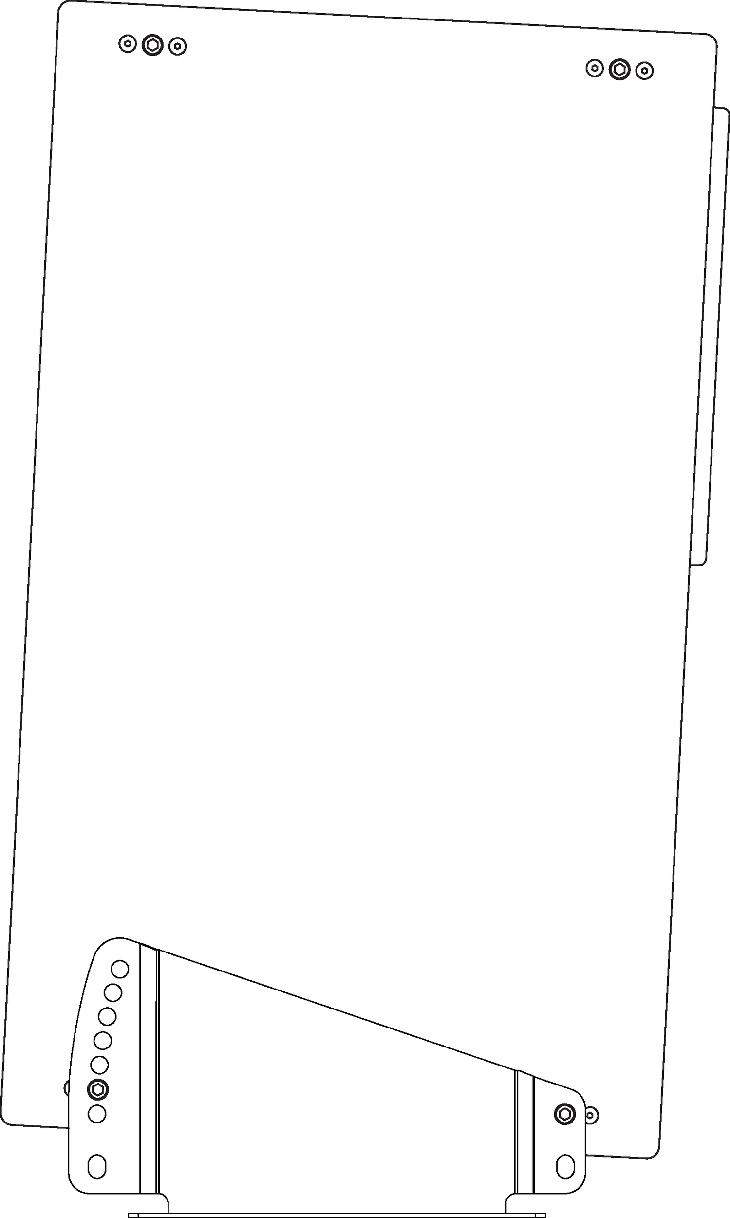
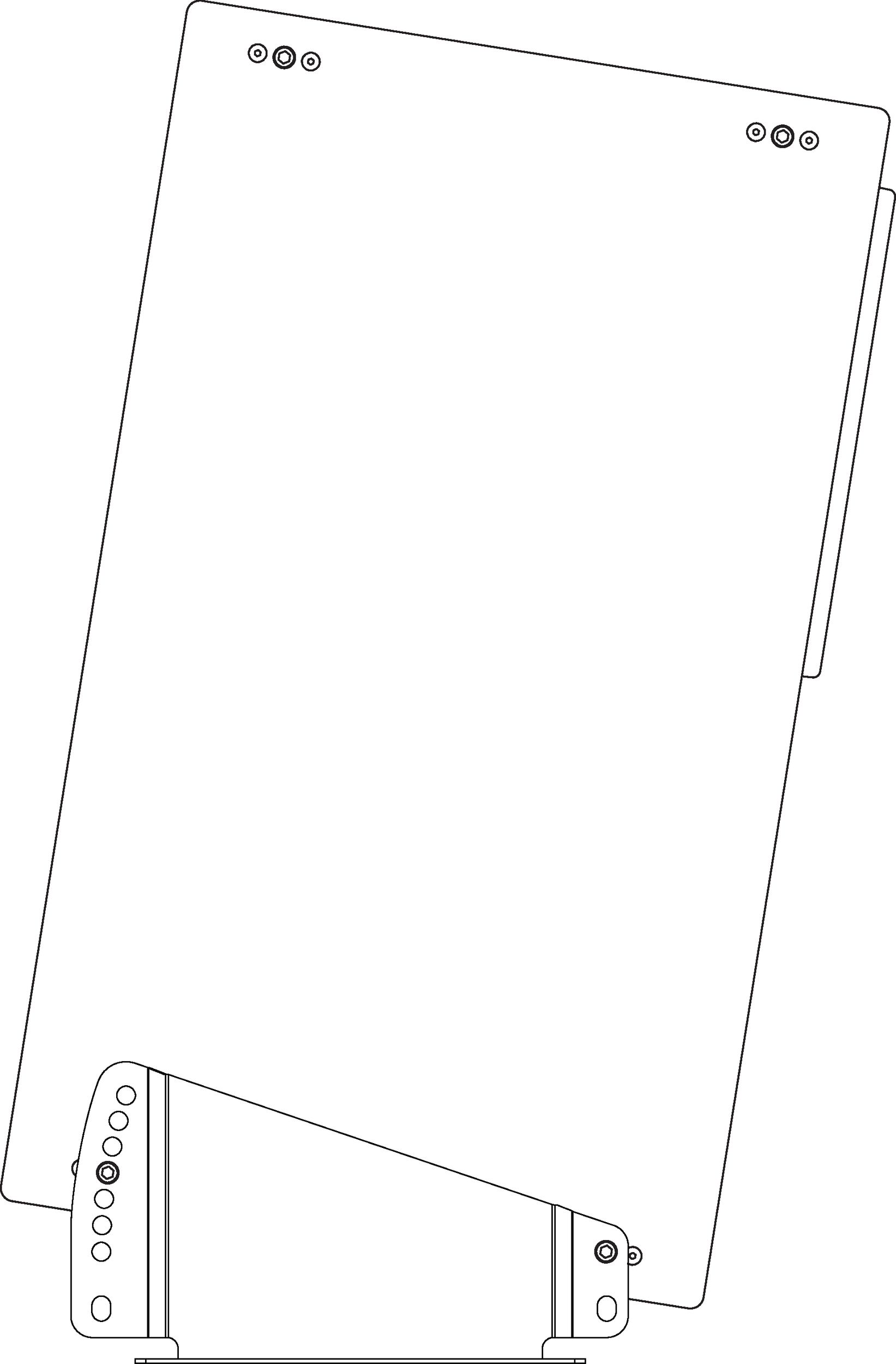
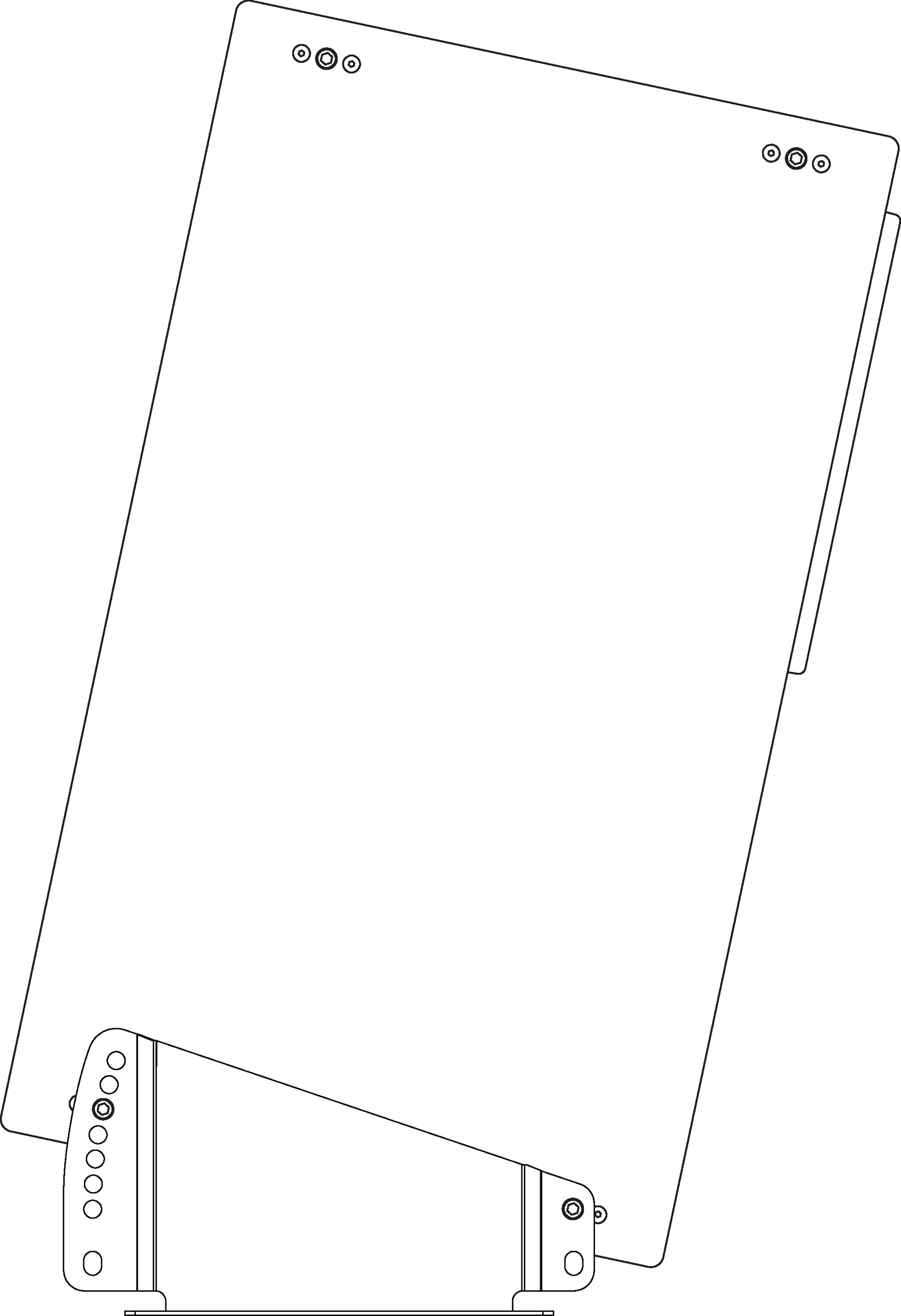
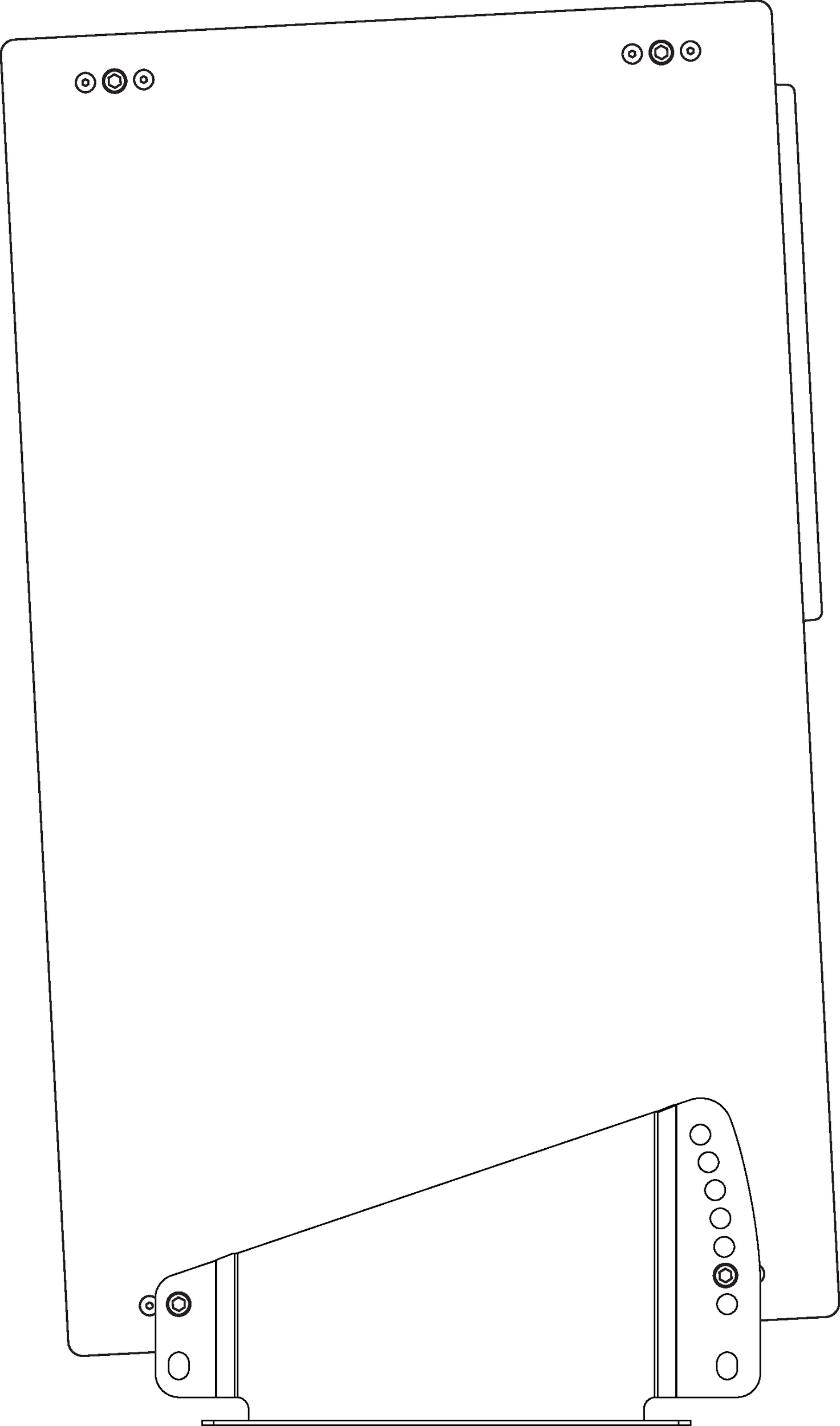
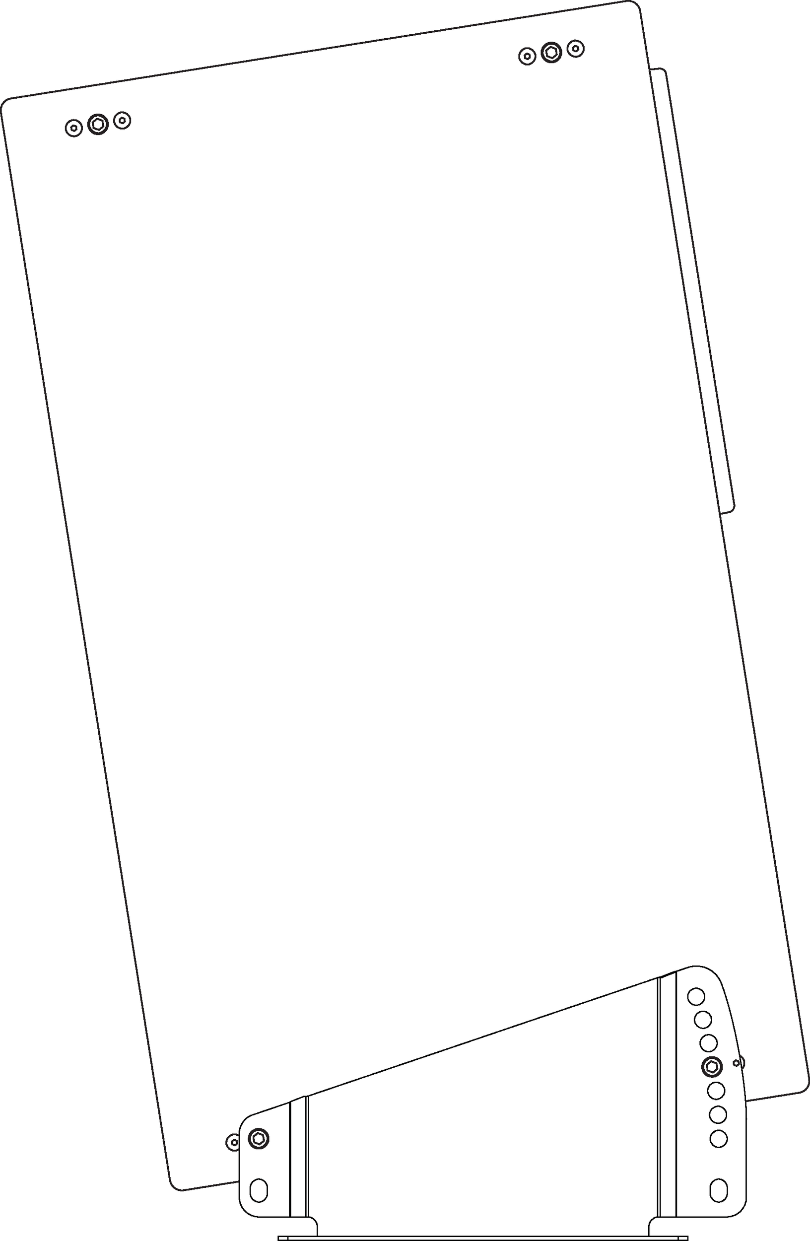
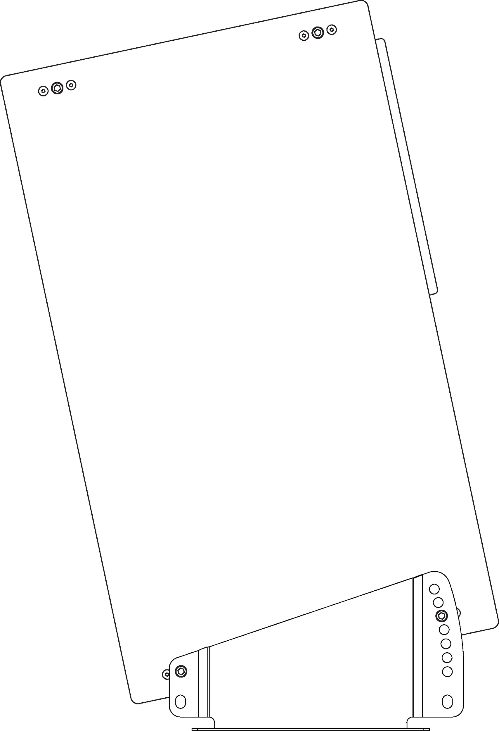
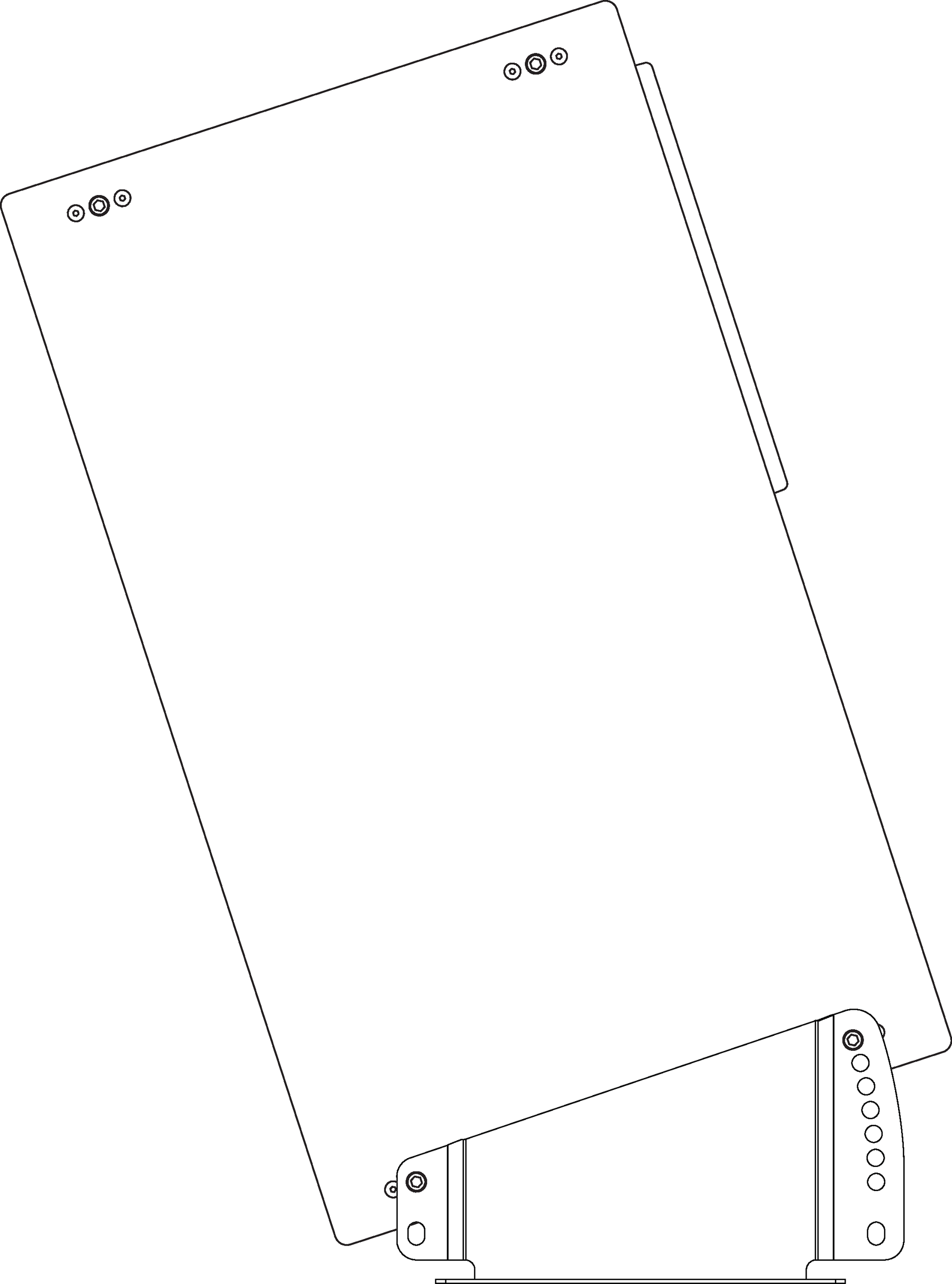
When the floor mount brackets are oriented with the bracket’s large end toward the rear of the loudspeaker, the Acheron can be mounted with downtilt angles of 3-18 degrees in 3-degree increments.
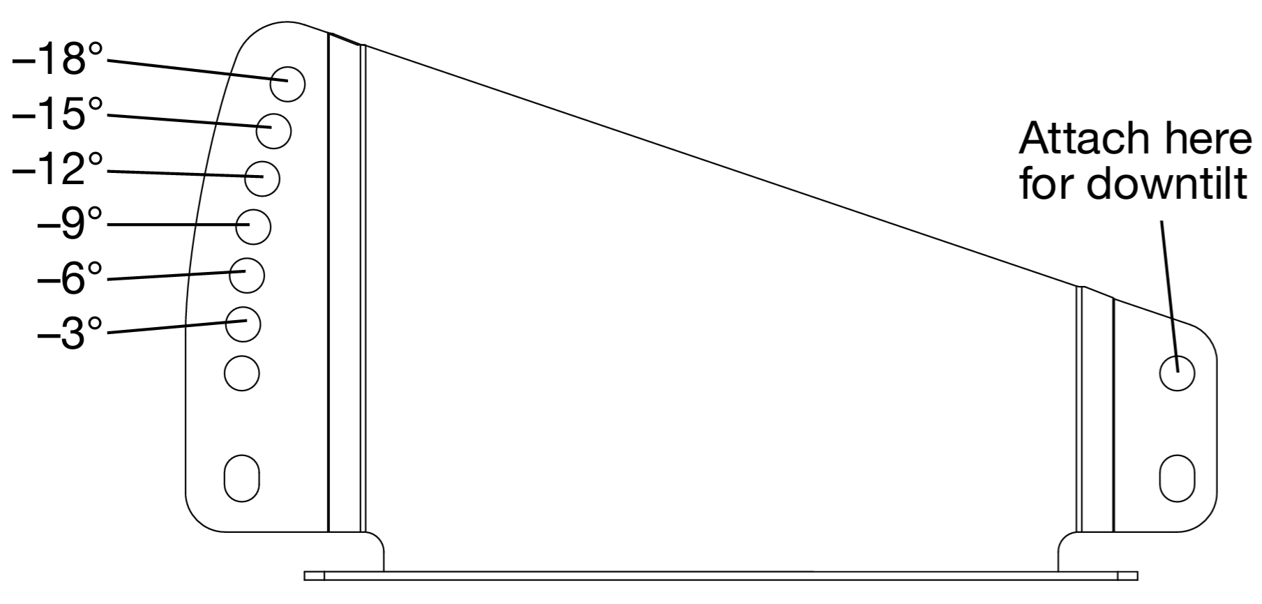 |
Acheron Floor Mount Bracket Oriented for Downtilt
The small end of the bracket attaches to the loudspeaker using the top hole. The large end of the bracket attaches to the loudspeaker with one of the angled holes.
Figure 1. –3°
| Figure 2. –6°
| ||
Figure 3. –12°
| Figure 4. –18°
|
Floor Mount Uptilt Angles
When the floor mount brackets are oriented with the bracket’s large end toward the front of the loudspeaker, the Acheron can be mounted with uptilt angles of 3-18 degrees in 3-degree increments.
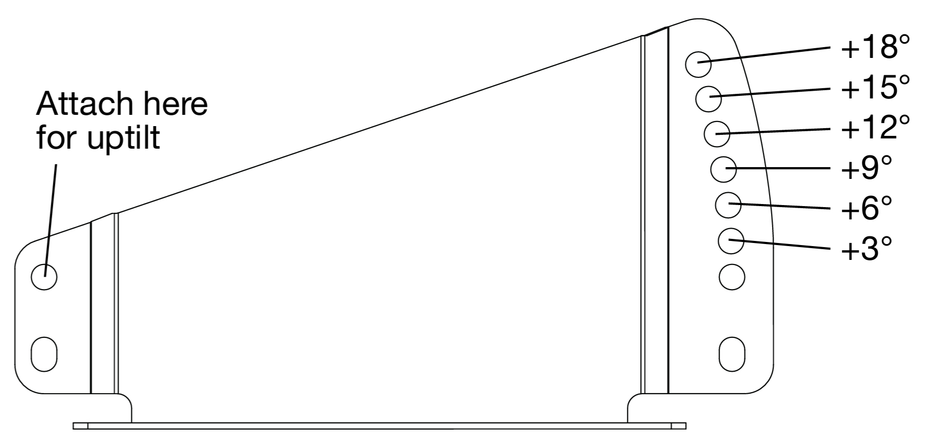 |
Acheron Floor Mount Bracket Oriented for Uptilt
The small end of the bracket attaches to the loudspeaker using the top hole. The large end of the bracket attaches to the loudspeaker with one of the angled holes.
Figure 5. +3°
| Figure 6. +6°
| ||
Figure 7. +9°
| Figure 8. +12°
|
Acheron Stacking Bracket
One Acheron can be stacked on top of the Acheron LF and secured with the Acheron stacking brackets. The stacked Acheron can be mounted with downtilt and uptilt angles of 0–16 degrees.
Note
The orientation of the Acheron to the Acheron LF with the stacking bracket was carefully optimized to minimize any acoustical artifacts between the loudspeakers, as well as between the loudspeakers and baffle walls.
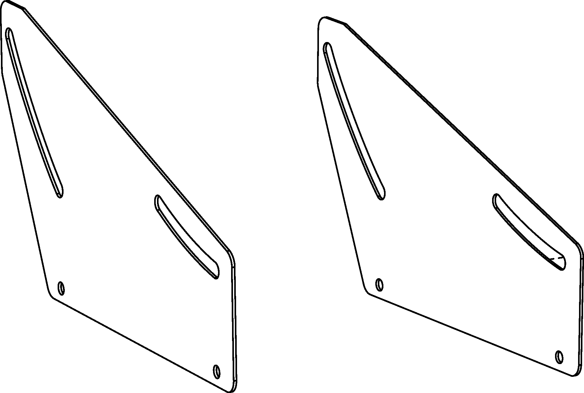 |
Acheron Stacking Brackets
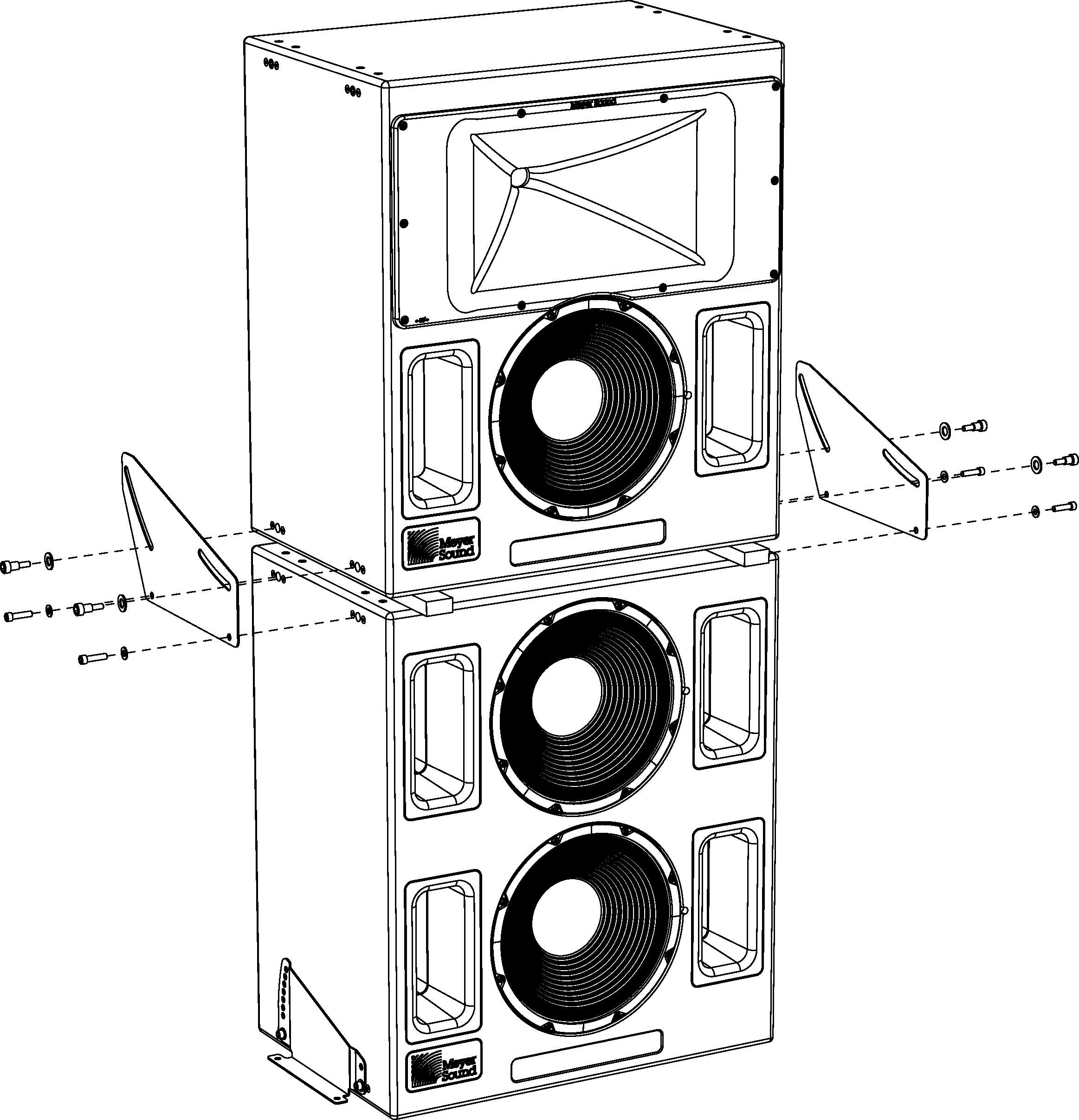 |
Acheron and Acheron LF with Stacking Brackets
Caution
When stacking an Acheron on top of an Acheron LF, the Acheron LF must be secured to the floor with the floor mount brackets. Floor-mount the Acheron LF at 0 degrees using the bottom bracket holes.
Acheron Stacking Bracket Kit Contents
The Acheron stacking bracket kit (PN 40.188.025.01) includes the following parts.
Part | Part number | Quantity |
|---|---|---|
Acheron stacking bracket (left) | 45.188.043.01 | 1 |
Acheron stacking bracket (right) | 45.188.044.01 | 1 |
3/8-16 x 1.5” shoulder screws | 101.507 | 4 |
Large 1/2” flat washers | 113.531 | 4 |
Small Flat washers | 113.509 | 4 |
Note
The 3/8-16 x 1.5-inch screws required for securing the stacking bracket to the Acheron LF are shipped with the Acheron LF installed in the top two screw holes on each side of the unit (four total).
Stacking Acherons on Acheron LFs
Secure the Acheron LF to the floor with the floor mount brackets at 0 degrees using the bottom bracket holes. For more information, see Floor Mounting Acherons and Acheron LFs
Stack the Acheron on top of the Acheron LF.
Tip
Optionally place two 1 x 2-inch wood pieces (not included) across the top of the Acheron LF, between it and the Acheron. The resulting extra space between the loudspeakers will make it easier to align the Acheron screw holes with the brackets.
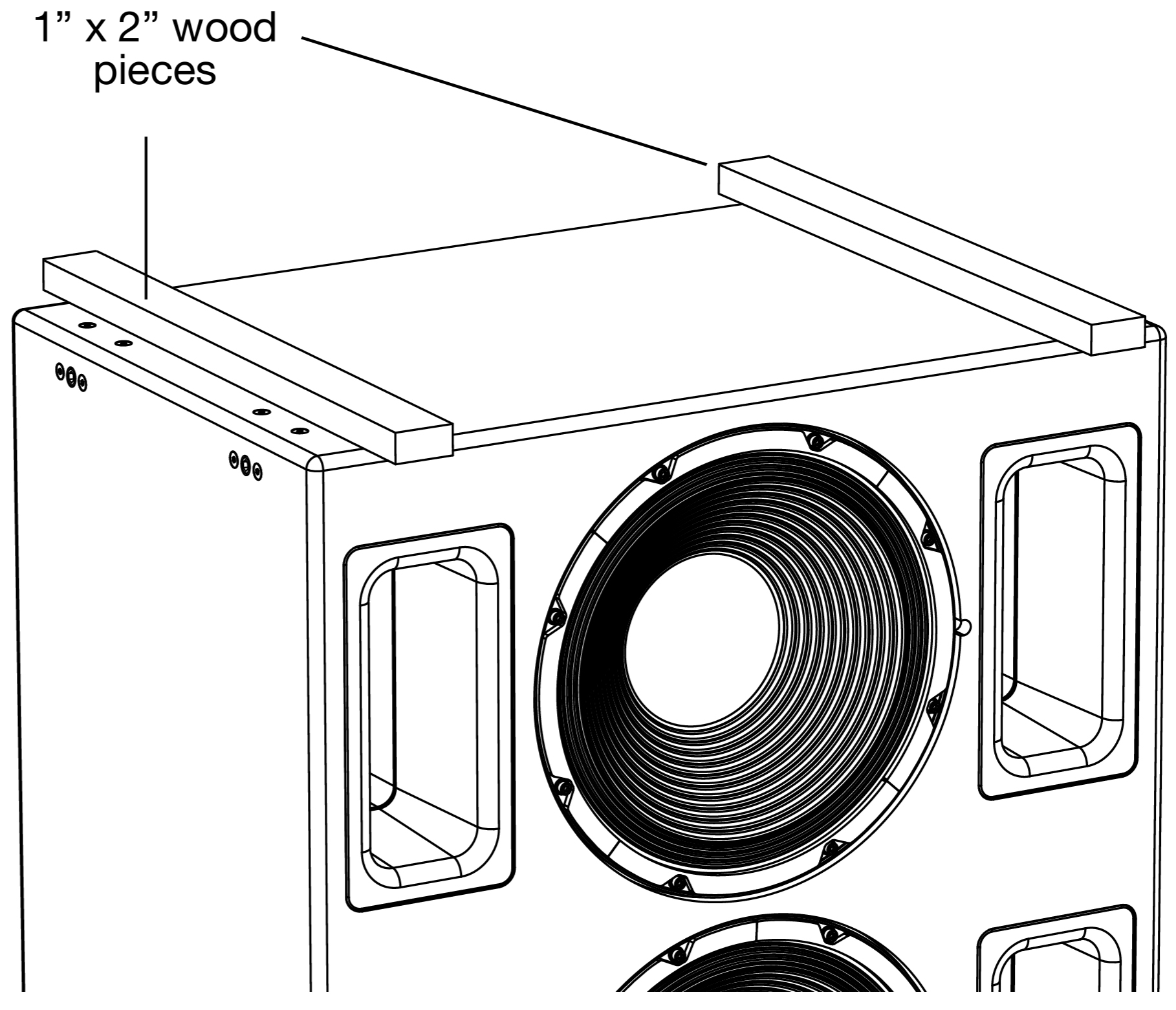
Remove the two 3/8-16 x 1.5-inch screws at the top of each side of the Acheron LF (four total). These screws will be used to secure the stacking bracket to the Acheron LF.
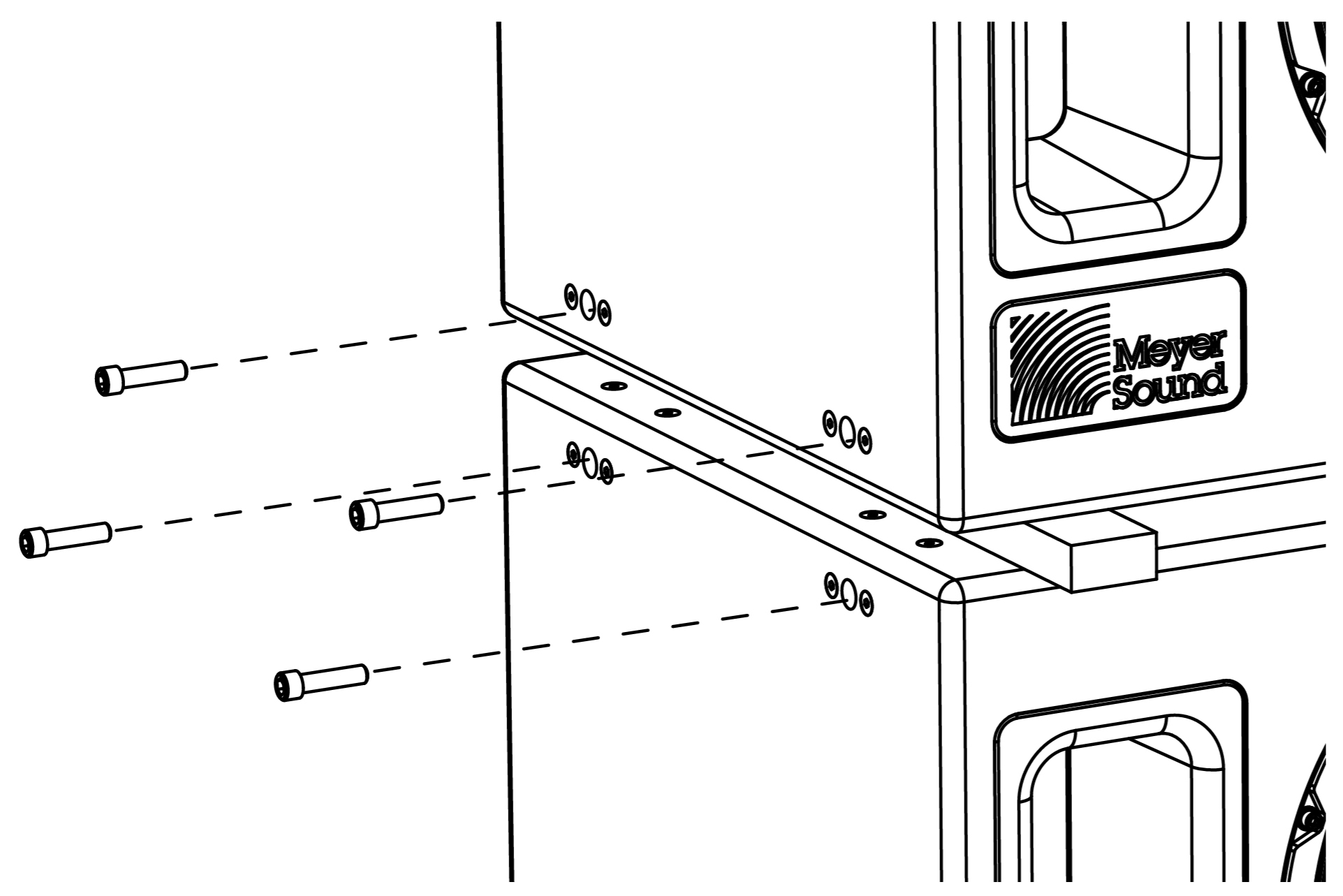
Remove the two 3/8-16 x 1.5-inch screws at the bottom of each side of the Acheron (four total). These screws will not be needed for installing the stacking bracket.
Secure the left bracket to the left side of the Acheron LF with two of the removed screws and two of the small flat washers (included in the Acheron stacking bracket kit). Use the bracket’s bottom screw holes and install the bracket so its rubber gasket faces the loudspeaker.
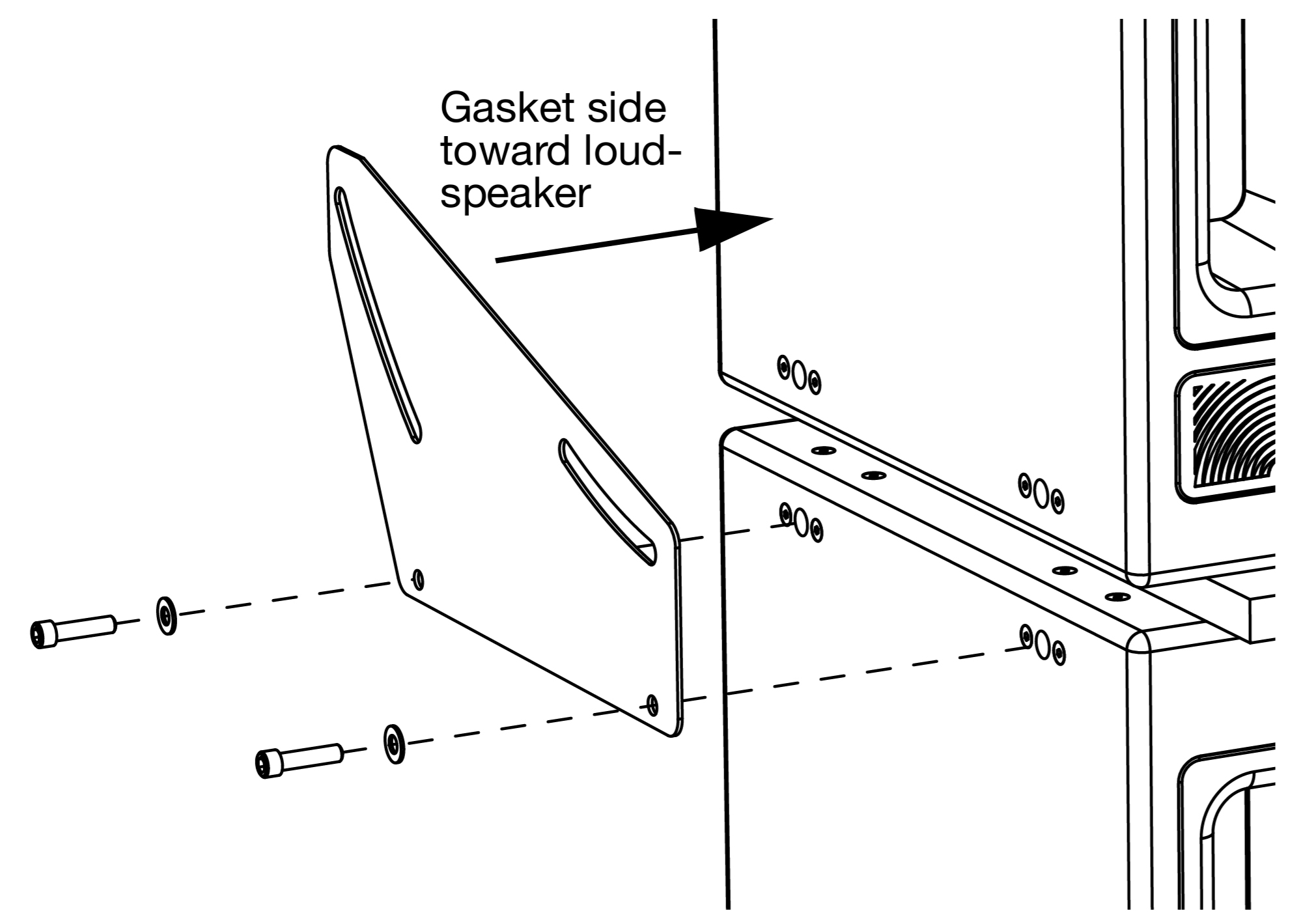
To mount the Acheron with downtilt, orient the bracket with the large end toward the rear of the loudspeakers. For available downtilt angles, see Stack Mount Downtilt Angles
To mount the Acheron with uptilt, orient the bracket with the large end toward the front of the loudspeakers. For available uptilt angles, see Stack Mount Uptilt Angles
Secure the right bracket to the right side of the AcheronLF with the remaining two screws (previously removed) and the remaining two small flat washers. Install the bracket so its rubber gasket faces the loudspeaker.
Secure the stacking brackets to the Acheron with the four 3/8-16 x 1.5-inch shoulder screws and four large 1/2-inch washers (both included with the Acheron stacking bracket kit). Insert the shoulder screws in the bracket’s top slots but don’t yet tighten them completely.
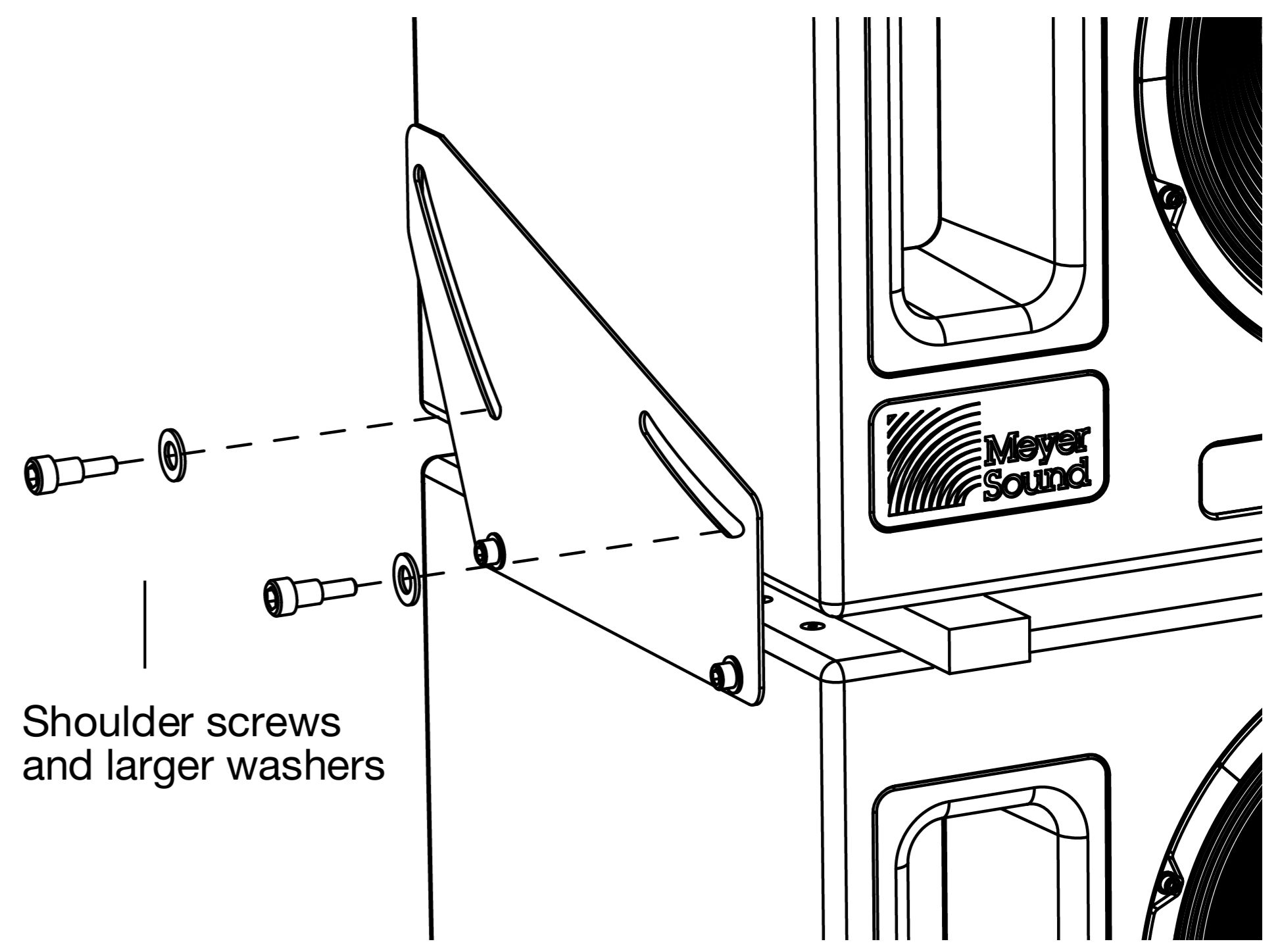
Tip
If necessary, tip the Acheron slightly to align its screw holes with the bracket holes.
Adjust the angle of the stacked Acheron — anywhere between 0 and 16 degrees — by tilting the unit up or down so the screws slide through bracket slots.
Tighten all four shoulder screws to secure the stacking bracket to the Acheron.
Stacking Acherons with Downtilt and Uptilt
The Acheron stacking brackets can mount Acherons with either downtilt or uptilt. Available angles are anywhere from 0–16 degrees. The direction in which the brackets are oriented determines whether the loudspeaker can be mounted with downtilt or uptilt.
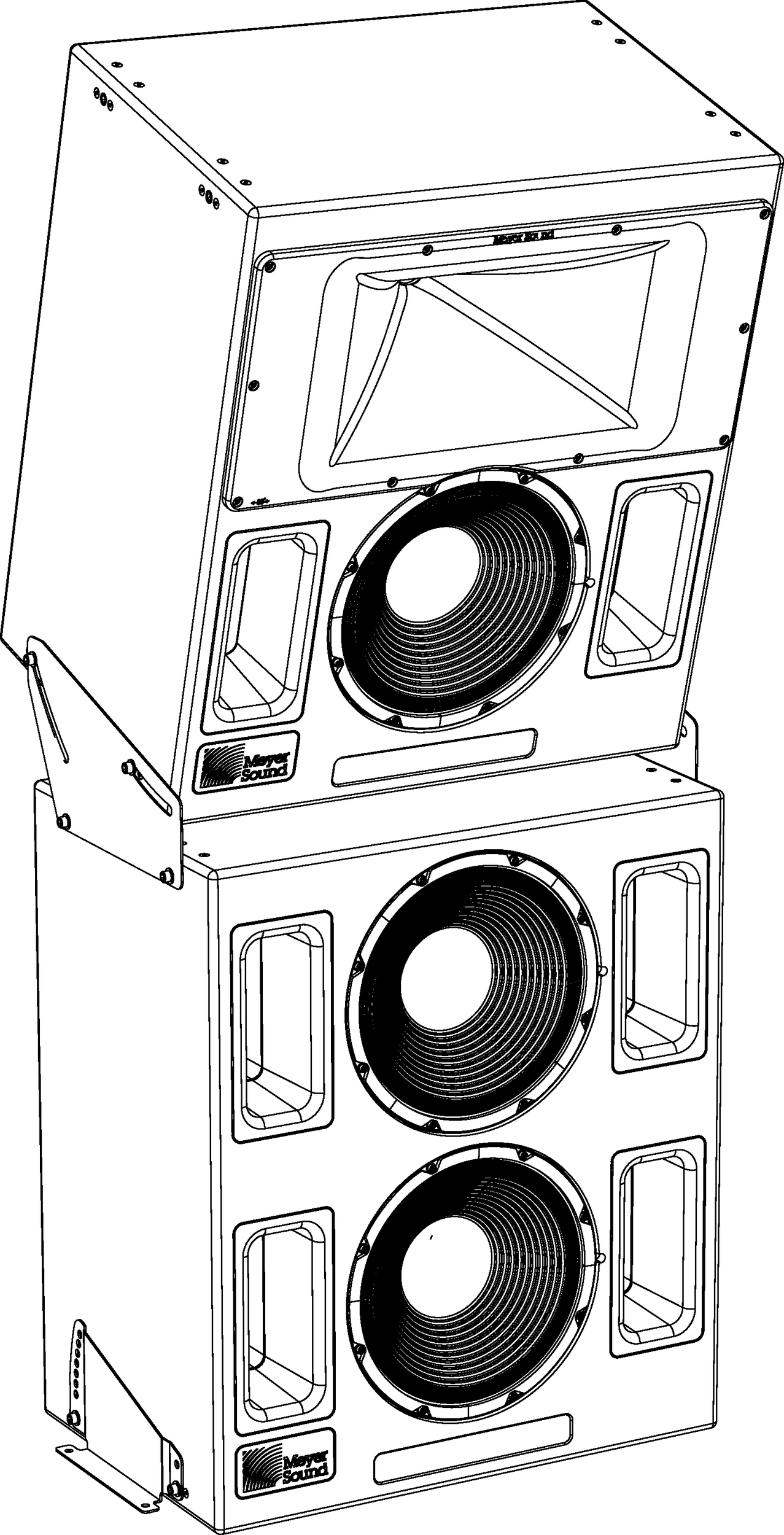 |
AcheronLF and Stacked Acheron with 16-Degree Downtilt
Caution
When stacking an Acheron on top of an Acheron LF, the Acheron LF must be secured to the floor with the floor mount brackets. In addition, the Acheron LF should not be mounted with downtilt or uptilt.
Stack Mount Downtilt Angles
When the stacking brackets are oriented with the bracket’s large end toward the rear of the loudspeakers, the Acheron can be mounted with downtilt angles of up to 16 degrees.
Make sure to install the brackets so the rubber gasket faces the loudspeaker. This ensures that the loudspeaker will not get scratched when adjusting the downtilt angle.
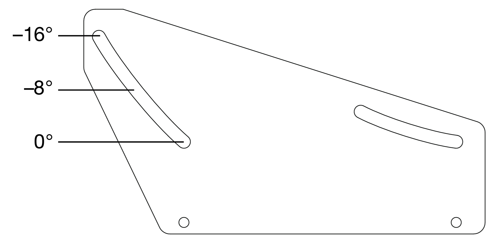 |
Acheron Floor Mount Bracket Oriented for Downtilt
Make sure to install the brackets so the rubber gasket faces the loudspeaker. This ensures that the loudspeaker will not get scratched when adjusting the downtilt angle.
Figure 9. +8°
| Figure 10. +16°
|
Acheron Floor Mount Downtilt Angles
Stack Mount Uptilt Angles
When the stacking brackets are oriented with the bracket’s large end toward the front of the loudspeakers, the Acheron can be mounted with uptilt angles of up to 16 degrees.
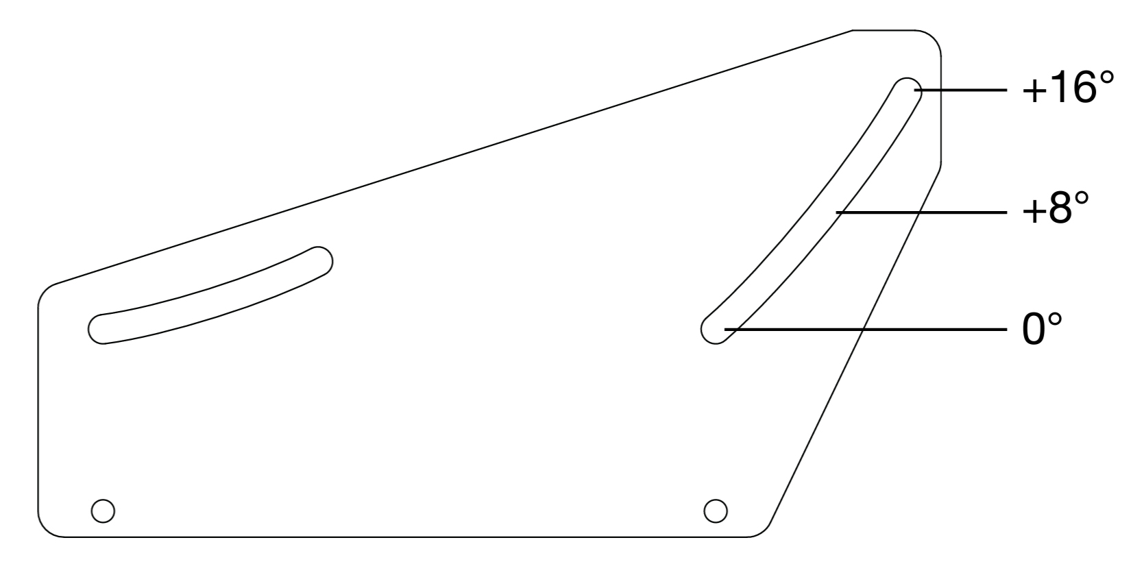 |
Acheron Floor Mount Bracket Oriented for Uptilt
Make sure to install the brackets so the rubber gasket faces the loudspeaker. This ensures that the loudspeaker will not get scratched when adjusting the uptilt angle.
Figure 11. +8°
| Figure 12. +16°
|
Acheron RMS Remote Monitoring System
The Acheron loudspeaker optionally includes an RMS remote monitoring system module, allowing it to be connected to an RMS network. RMS reports, in real time, the status and power usage of multiple Meyer Sound loudspeakers from a Mac® or Windows®-based computer. The RMServer™ communicates with Meyer Sound loudspeakers equipped with RMS modules. RMServer is a compact, Ethernet-based hardware unit with two FT-10 RMS data ports. RMServer stores system configurations internally, eliminating most manual data entry. Systems can be monitored from a computer at front-of-house or backstage, or from a laptop anywhere within the venue over WiFi.
Note
RMS does not control AC power.
RMS-equipped loudspeakers include a Mute Jumper to enable the loudspeaker’s mute and solo capability. Meyer Sound currently ships RMS-equipped loudspeakers with the Mute Jumper installed. These mute-enabled loudspeakers can be identified by the blue “ME” sticker on the face of the RMS module. Older RMS-equipped loudspeakers can easily be mute-enabled by installing the Mute Jumper. For more information, refer to the RMServer Hardware Guide (PN05.222.024.01).
The RMS software allows disabling of the Mute and Solo functions to eliminate any possibility of accidentally muting loudspeakers. Mute and solo capability can also be disabled by removing the Mute Jumper from RMS modules. For more information, refer to the RMServer Quick Start Guide (PN 05.222.005.01).
Compass RMS Software
Compass RMS™ software provides extensive system status and performance data for each loudspeaker, including amplifier voltage, limiting activity, power output, heat sink temperature, fan and driver status, as well as mute and solo capability. Loudspeakers are added to the RMS network and assigned a node name during a one-time discovery procedure. Once loudspeakers are identified on the RMS network, they appear in Compass RMS as icons that can be customized, as shown in the figure below.

Compass RMS Window
Individual loudspeakers can be physically identified with the Wink option in RMS, which lights the Wink LED on the RMS module of that particular loudspeaker. Loudspeaker icons can be arranged in Compass RMS and saved as pages to represent how the loudspeakers have been deployed in the system. Multiple pages can be saved and recalled for specific performances and venues.
RMS Module
The RMS user panel includes three LEDs, two buttons, and two Network connectors.
 |
RMS Module
Note
The LEDs and buttons on the RMS user panel are used exclusively by RMS and have no effect on the acoustical or electrical activity of the loudspeaker.
Service LED (Red)
The red Service LED provides the following feedback:
When unlit, the loudspeaker is successfully connected to the network and commissioned.
When blinking once every two seconds, the loudspeaker is connected to the network but not yet commissioned in the RMS software.
When lit continuously, the loudspeaker’s RMS hardware has failed and may indicate that the module has been damaged (contact Meyer Sound Technical Support).
Service Button
Pressing the Service button identifies the loudspeaker on the RMS network and notifies the RMS software that the loudspeaker is connected. Simultaneously press the Reset and Service buttons to reset the RMS module and decommission the loudspeaker from the network (see Resetting the RMS Module).
Wink LED (Green)
The green Wink LED lights when a signal is sent from the RMS software by clicking the Wink button on the loudspeaker’s icon or on its Text view. This feature is useful for identifying the physical loudspeaker corresponding to a loudspeaker icon in the RMS software.
Reset Button
Pressing the Reset button causes the RMS module’s firmware to reboot; this action will not affect whether the loudspeaker is commissioned (which is stored in flash memory). Simultaneously press the Reset and Service buttons to reset the RMS module and decommission the loudspeaker from the network (see Resetting the RMS Module ).
Activity LED (Green)
The green Activity LED flashes continuously when the loudspeaker has been successfully commissioned.
Network Connectors
The two Weidmuller connectors transfer data to and from the RMS network. Two connectors are provided to allow for easy connection of multiple (daisy-chained) loudspeakers on the network. Included with each RMS-equipped loudspeaker are RMS cable connectors and mounting blocks for constructing RMS cables. The RMS blocks allow the cables to be securely attached to the RMS module with screws.
Resetting the RMS Module
Use the Reset and Service buttons to reset the RMS module, which will cause the module to be decommissioned from the network.
Press and hold the Service button for 10 seconds.
While continuing to hold down the Service button, press and hold the Reset button for 5 seconds.
After releasing the Reset button, continue holding down the Service button for 5 seconds. The RMS module is reset and the loudspeaker is decommissioned. The RMS module’s red Service LED blinks.
System Design and Integration Tools
MAPP System Design Tool
The MAPP System Design Tool is a powerful, cross-platform application for accurately predicting the coverage pattern, frequency response, phase response, impulse response, and SPL capability of individual or arrayed Meyer Sound loudspeakers.

MAPP System Design Tool
Whether planning for fixed installations or for tours with multiple venues, use MAPP to accurately predict the appropriate loudspeaker deployment for each job, complete with coverage data, system delay and equalization settings, rigging information, and detailed design illustrations. MAPP’s accurate, high-resolution predictions ensure that systems will perform as intended, thereby eliminating unexpected coverage problems and minimizing onsite adjustments.
The key to the accuracy of MAPP’s predictions is MeyerSound’s exhaustive database of loudspeaker measurements. Performance predictions for each loudspeaker are based on 3-dimensional, 65,000+ 1/48th-octave-band measurements taken in the MeyerSound anechoic chamber. The extraordinary consistency between Meyer Sound loudspeakers guarantees that predictions from MAPP will closely match their actual performance.
MAPP software allows for configuration of MeyerSound loudspeaker systems and definition of the environment in which they operate, including air temperature, pressure, humidity, and the location of prediction surfaces. Importing both CAD (.DXF) and Sketchup (.SKP) files containing detailed venue information to act as an anchor model to the prediction surfaces and a visual aid to facilitate prediction data interpretation is also possible.
Tip
See meyersound.com for support and more information about MAPP.
MAPP Capabilities
With MAPP, you can:
Simulate different loudspeaker configurations to refine system designs and determine the best coverage for intended audience areas
Model loudspeaker interactions to locate constructive and destructive interferences so that loudspeakers can be re-aimed and repositioned as necessary
Place microphones anywhere in the Model View space and predict loudspeaker frequency response, phase response, and sound pressure levels at each microphone position
Determine delay settings for fill loudspeakers using the Inverse Fast Fourier Transform and phase response feature
Preview the results of signal processing to determine optimum settings for the best system response
Automatically calculate load information for arrays to determine necessary minimum rigging capacity, front-to-back weight distribution, and center of gravity location
Generate and export system images and system PDF reports for client presentations
Synchronize GALAXY processor output channel settings in real-time with virtual or real GALAXY units, allowing in-the-field changes to be predicted during system alignments
Galileo GALAXY Network Platform
The Galileo GALAXY Network Platform is a sophisticated loudspeaker management tool for controlling all MeyerSound speaker types. The GALAXY loudspeaker processor extends a high level of audio control in driving and aligning loudspeaker systems with multiple zones. It provides a powerful tool set for corrective equalization (EQ) and creative fine-tuning for a full range of applications from touring to cinema.
Users can readily program the GALAXY processor using Compass software running on a host computer or via the Compass Go application for the iPad. Connecting MAPP to the GALAXY processor will also allow the user to push output channel settings created in MAPP as a starting point. Compass Control Software includes custom-designed settings for each family of speakers, as well as to integrate families together. For example, the Product Integration feature matches the phase characteristics between Meyer speaker families to ensure the most coherent summation.
Processing tools for inputs and outputs include delay, parametric EQ and U-Shaping EQ. Output processing also includes polarity reversal, Low-Mid Beam Control (LMBC), atmospheric correction, and All Pass filters.
The built-in summing and delay matrices allow a user to easily assign gain and delay values, respectively, at each cross point. This capability greatly facilitates using one loudspeaker to satisfy multiple purposes.
Front panel controls let a user intuitively and quickly operate a GALAXY processor without a computer during live use.
The GALAXY 408, GALAXY 816 and GALAXY 816-AES3 processor versions have the same audio processing capability with different I/O. See www.meyersound.com to locate their datasheets for more information.
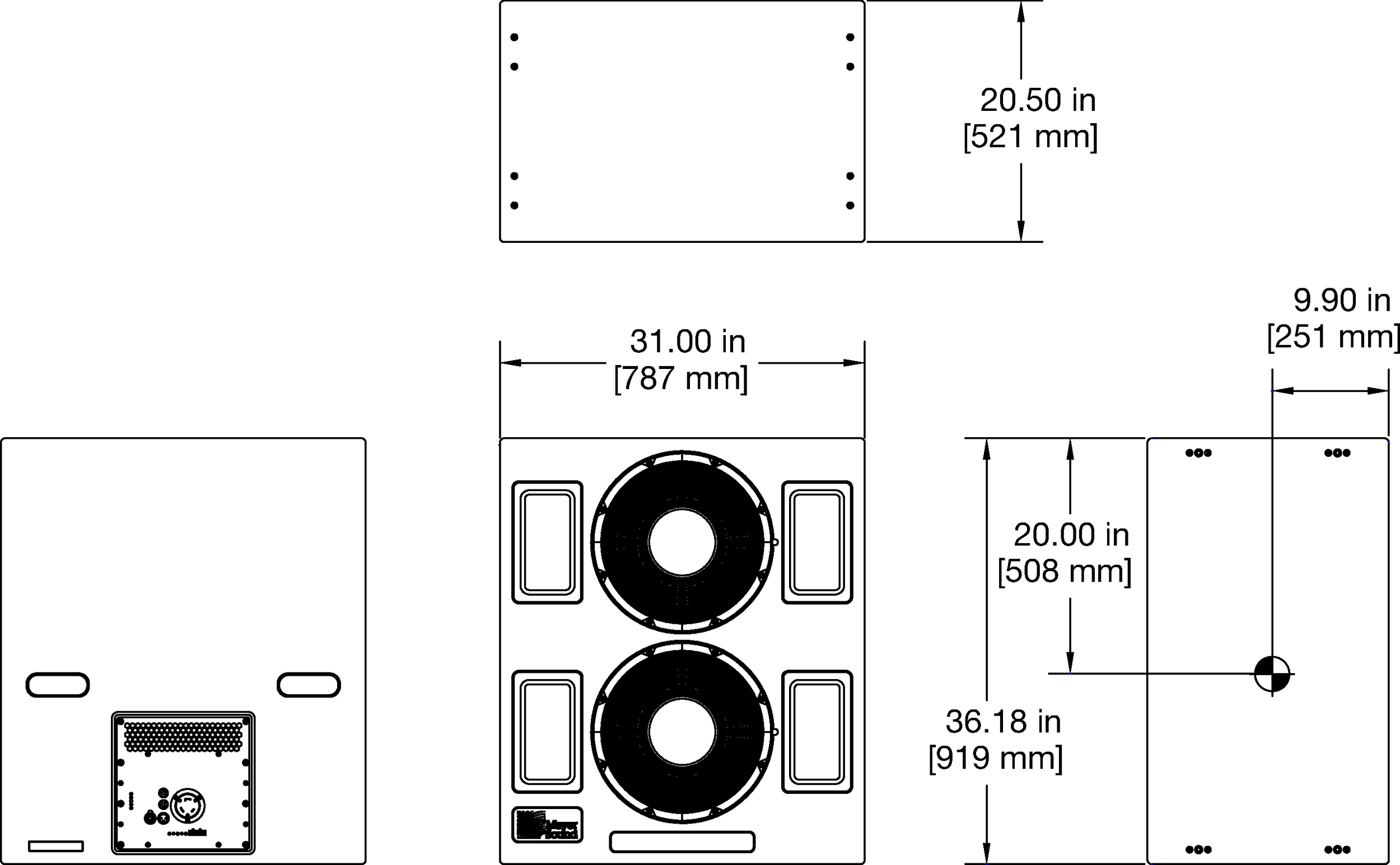
Acheron 80 Dimensions
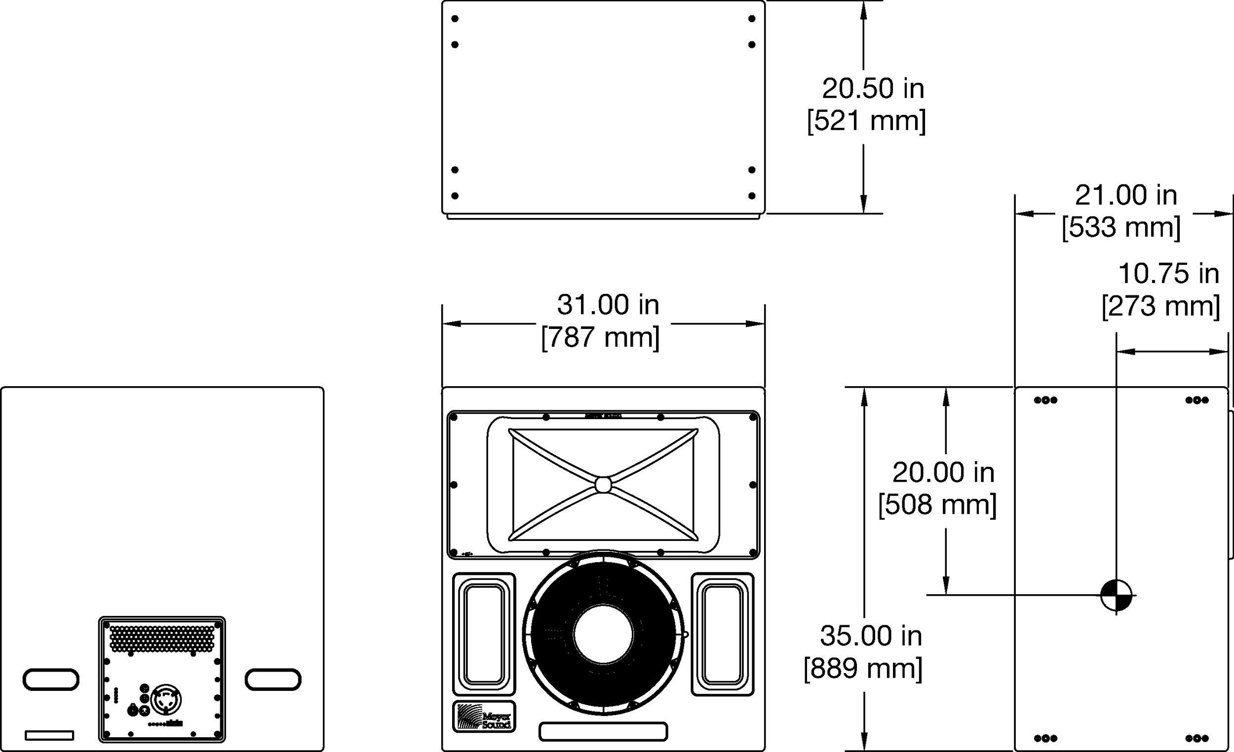
Acheron 100 Dimensions
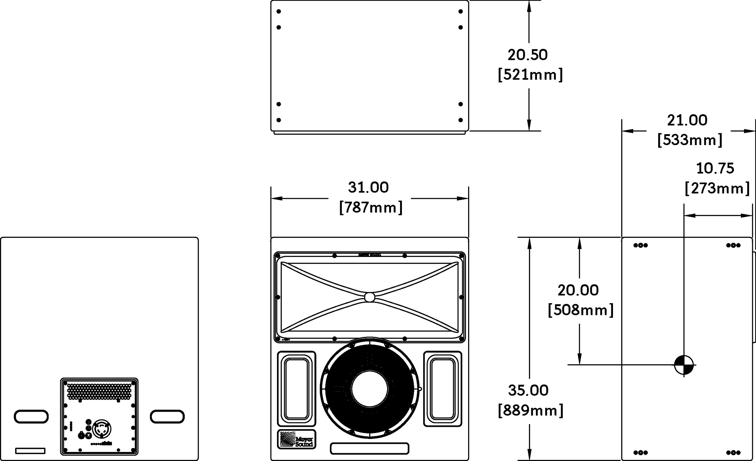
Acheron LF Dimensions
