User Guide — Galileo GALAXY
Network platform
The Galileo GALAXY Network Platforms contain audio processors that are sophisticated loudspeaker management tools offering comprehensive control of Meyer Sound loudspeaker systems. They provide powerful tool sets for corrective equalization and creative fine-tuning in fully networkable devices.
Note
For expediency in the following documentation, the Galileo GALAXY Network Platform is referred to as the “GALAXY processor” or, where appropriate, by specific models such as “GALAXY 408 processor,” “GALAXY 816 processor,” and “GALAXY 816-AES3 processor.” Similarly, Compass Control Software is simply called “Compass” or “Compass Go.”
Powerful audio processing
GALAXY processors feature a 96 kHz audio processing sample rate and use 24-bit/96 kHz A/D and D/A converters. Input processing tools include gain, delay, 5-band parametric EQ, and 5-band U-Shaping EQ. Output processing tools include gain, delay, polarity reversal, 10-band parametric EQ, 5-band U-Shaping EQ, Low-Mid Beam Control (LMBC, see Low-Mid Beam Control (LMBC)), atmospheric correction (see Atmospheric correction), high- and low-pass filters, and all-pass filters. Built-in summing and delay matrices allow users to easily assign gain and delay values at each routing cross-point, enabling any single loudspeaker to serve as an output for multiple, independently processed input signals. The Product Integration feature combines the Delay Integration setting and Starting Points (saved channel settings) capability into a single dialog. This feature facilitates the optimization of systems to achieve the best possible performance.
The GALAXY 408 processor, the GALAXY 816 processor, and the GALAXY 816-AES3 processor have the same audio processing capability with different physical inputs and outputs. The GALAXY 816-AES3 processor also includes a BNC connection for external word clock input.
Extensive user control
Users can control any of the GALAXY processors using Compass Control Software (hosted on a Mac or PC) or via the Compass Go application for the iPad. Compass provides a complete toolkit for audio routing, system optimization, processing, and monitoring.
For units equipped with this component, the rear panel includes SIM 3 bus port(s) (one on the GALAXY 408 processor and two on both the GALAXY 816 processor and the GALAXY 816-AES3 processor) for direct connection to Meyer Sound’s SIM audio analyzer, allowing GALAXY processors to function as line switchers for the analyzer. With this capability, users can take measurements from any selection of GALAXY processor inputs and outputs without patching beyond a single connection to SIM.
Milan-certified network platform
Galileo GALAXY Network Platforms are Milan-certified, providing plug-and-play network interoperability with other Milan-certified devices via AVTP Audio Format (AAF) and Clock Reference Format (CRF) AVB streams. Milan is the application layer built onto the AVB network protocol that adds a framework of interoperability for professional AV devices. Milan certification denotes true network redundancy for AVB and control signals, as well as guaranteed on-time arrival and bandwidth reservations for AVB signals. For more information about networking the GALAXY processors, see User Guide — Managing AVB Networks.
Galileo GALAXY Network Platform features overview
GALAXY processors include the following features:
Complete system control, optimization, and monitoring with Compass Control Software for Mac and Windows-based computers
Mobile system control, optimization, and monitoring with the Compass Go application for iPad
5-band U-shaping on inputs and outputs
5-band parametric EQ on inputs and 10-band parametric EQ on outputs
High/low pass filters with slopes up to 48 dB per octave
All pass filters to change the phase relationship between various frequencies, while not altering the gain at any frequency
Product Integration [combines Delay Integration setting and Starting Points (saved channel settings) capability]
Fixed low latency system
Optional asynchronous sample rate converters for AES3 inputs
Cross-point delay and summing matrix
Atmospheric correction filters
Interoperability with other Milan-certified third-party hardware, which includes features such as:
Support for redundant AVB networks, allowing for fail-over without audio interruption
Communication of AVB timing data and audio signals via AAF packets (AVTP Audio Format)
Communication of AVB clock signals via CRF packets (Clock Reference Format)
Ability to synchronize multiple AVB signals across multiple GALAXY processors
Selectable input and output voltage scaling that make it compatible with most consoles
Integrable with the SIM Audio Analyzer System.
User-selectable AVB output points for routing measurement signals to other calibration tools
Access protection policies to enable restriction of the GALAXY processor settings accessible to each operator
Easy integration with third-party controllers, such as AMX and Crestron
GALAXY 408 processor input/output summary
The GALAXY 408 processor is a 1RU, 19-inch rack-mountable device with the following inputs/outputs:
4 processed inputs that can receive analog, AES3, or AVB signals
4 processed inputs that can receive only AVB signals
24 AVB unprocessed matrix inputs
8 outputs that can provide processed analog signals
16 outputs that can provide processed AVB signals via XLR connectors
6 output sources, each capable of sourcing an 8-channel AVB stream via RJ-45 connectors
 |
Galileo GALAXY 408 Processor Front and Rear Panels
GALAXY 816 processor input/output summary
The GALAXY 816 processor is a 2RU, 19-inch rack-mountable device with the following inputs/outputs:
8 inputs that can receive analog, AES3, or AVB signals
24 AVB unprocessed matrix inputs
16 outputs that can deliver processed analog and/or AVB signals via XLR connectors
6 output sources, each capable of sourcing an 8-channel AVB stream via RJ-45 connectors
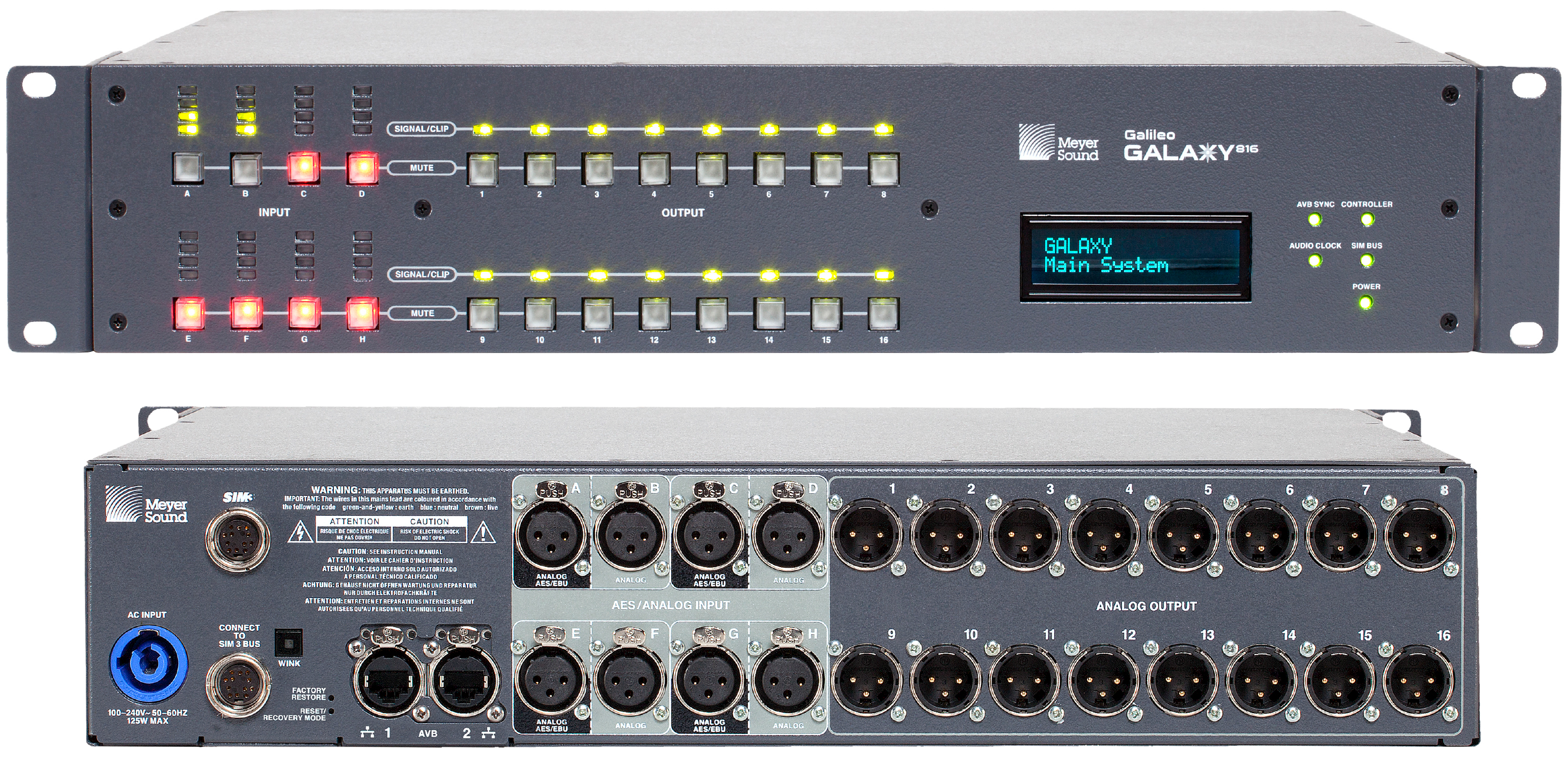 |
Galileo GALAXY 816 Processor Front and Rear Panels
GALAXY 816-AES3 processor input/output summary
The GALAXY 816-AES3 processor is a 2RU, 19-inch rack-mountable device with the following inputs/outputs:
8 inputs that can receive analog, AES3, or AVB signals
24 AVB unprocessed matrix inputs
16 outputs that can deliver processed AES3 or AVB signals via XLR connectors
8 outputs (9-16) that can deliver analog signals via XLR connectors
6 output sources, each capable of sourcing an 8-channel AVB stream via RJ-45 connectors
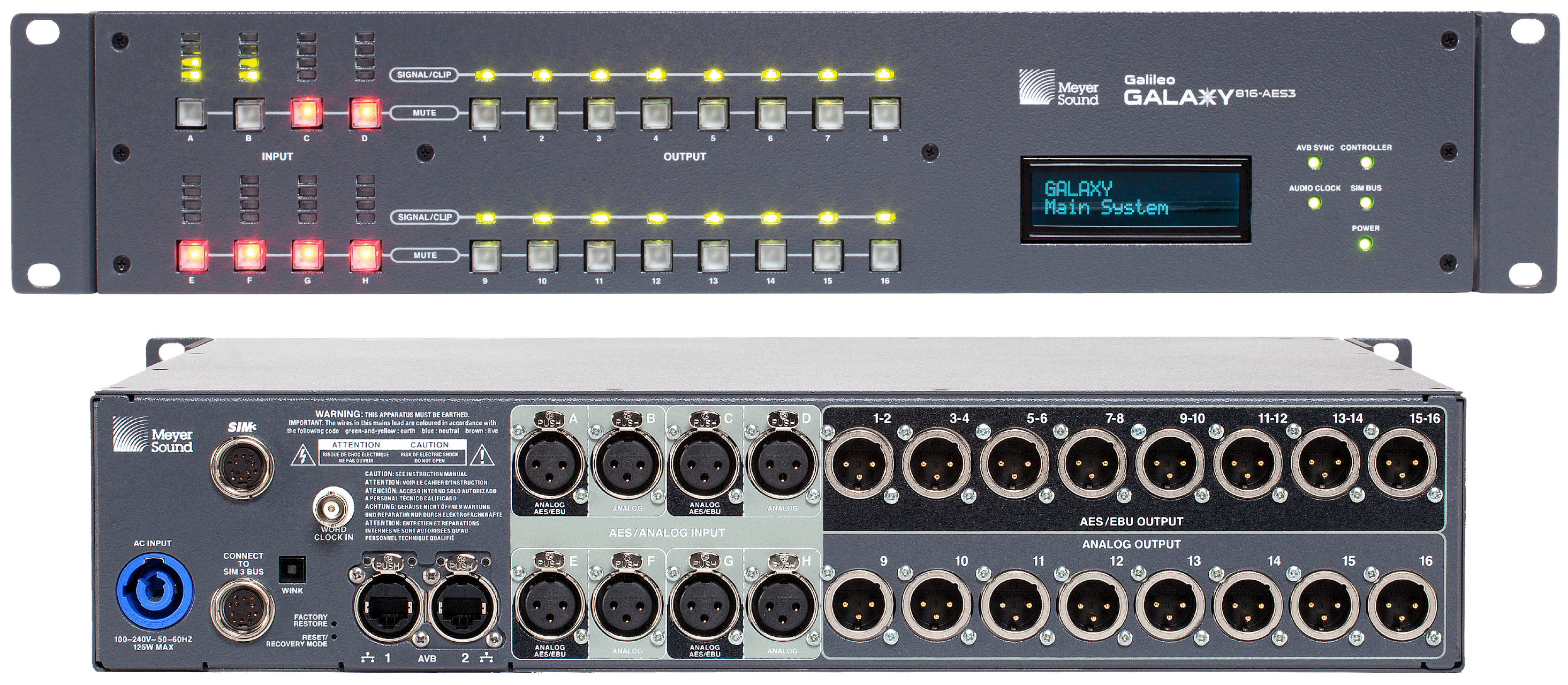
GALAXY 816-AES Processor Front and Rear Panels
GALAXY enclosures and I/O
All three GALAXY processors offer the same processing on inputs and outputs but differ in their size and physical connections. The GALAXY 816-AES3 processor also includes a BNC connector for external word clock input.
GALAXY processor enclosures
The three GALAXY processors are designed to be mounted in 19-inch wide racks. The GALAXY 408 processor is 1RU in height, and the GALAXY 816 processor and the GALAXY-816-AES processor are 2RU in height. The enclosures are made from steel with a slightly textured graphite gray finish.
GALAXY processor front panels
The GALAXY 816/816-AES and GALAXY 408 processor front panels, shown in the figure below, provide basic information and mute control of the loudspeaker management system.
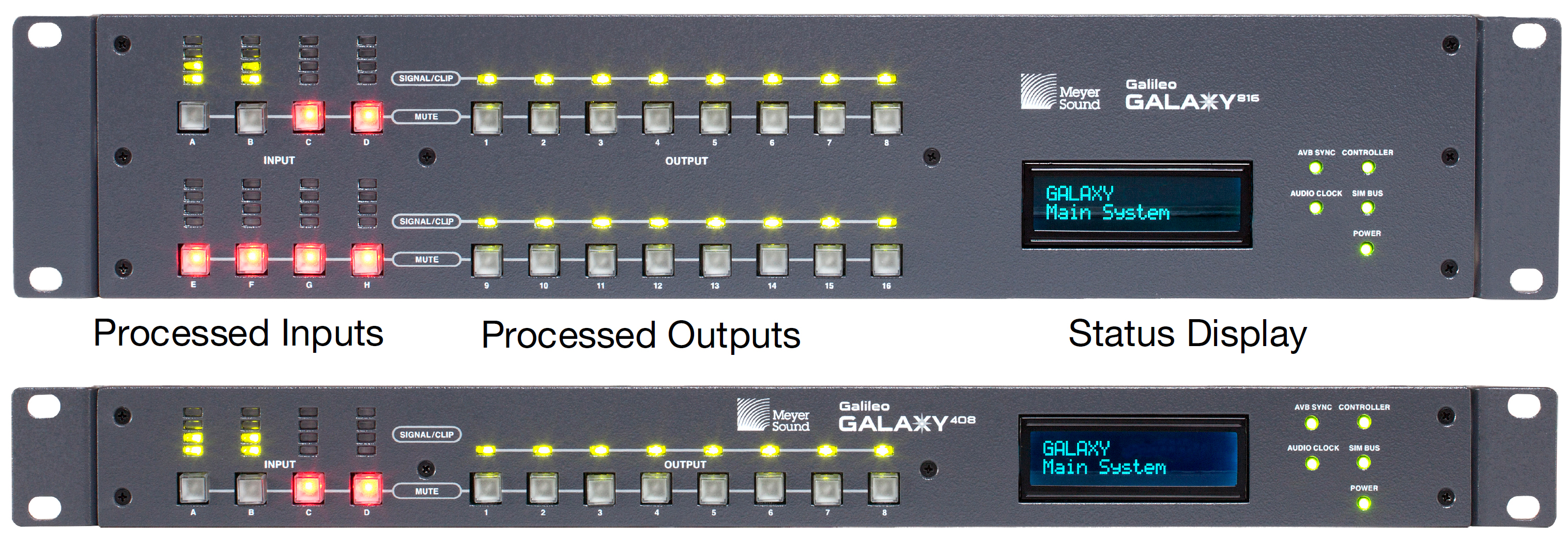
GALAXY front panels (816 and 816-AES are identical in the front, except for the name label)
The GALAXY front panel is divided into three sections:
Processed inputs
Processed outputs
Status display
Front panel processed inputs section
The GALAXY processor front panel processed inputs section is on the left side, as shown in the figure below, and consists of input level meters and input mute buttons.
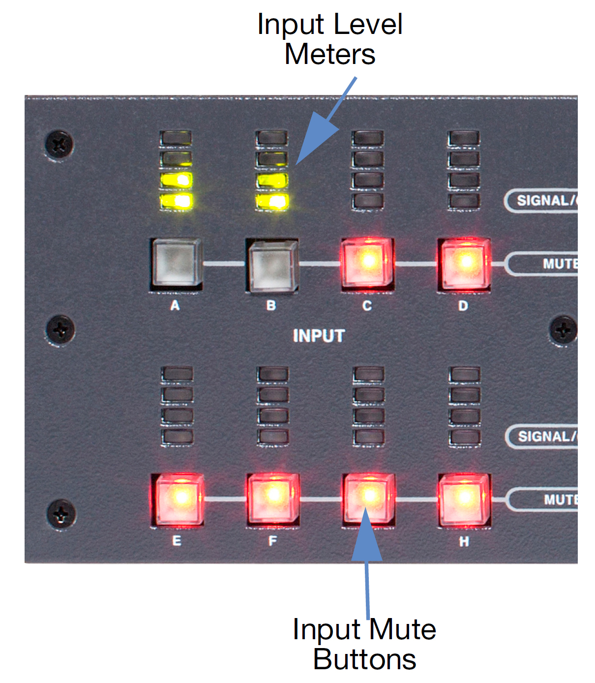
GALAXY processor front panel processed inputs section
Input level meters: Four-segment LED ladders represent the level for each input channel. The green LED range begins at approximately -80 dB below clipping. The yellow LED range lights a few dB below clipping. The top LED turns red as the input signal level reaches full-scale digital (0 dBFS). In Compass (Settings > Input and Output), the Voltage Range may be set for all input and output channels to either +16 dBu (4.89 V rms) or +26 dBu (15.5 V rms); this selection determines the clipping levels.
Note
The default input voltage range is +26 dBu.
Input mute buttons: Each input channel has a mute button. Toggling an input mute button in Compass also toggles this mute button.
Front panel processed outputs section
The GALAXY processor front panel processed outputs section is in the middle, as shown in the figure below, and consists of output signal/clip LEDs and output mute buttons.

GALAXY processor front panel processed outputs section
Signal / clip LEDs: Output level is indicated by one multi-color LED for each output channel. The LED turns green to indicate output levels from -85 dB to -5 dB below clipping. The LED glows brighter as the signal level increases. The LED turns amber to indicate levels from -5 dB to just below the clipping level. The LED turns red as the output signal level reaches full-scale digital (0 dBFS). In Compass (Settings > Input and Output), the Voltage Range for all input and output channels can be set to either +16 dBu (4.89 V rms) or +26 dBu (15.5 V rms); this setting determines the clipping levels.
Note
The default output voltage range is +26 dBu.
Output mute buttons: Each output channel has a mute button. Toggling an output mute button in Compass also toggles this mute button.
Front panel status display section
The GALAXY processor front panel status display is on the right side, as shown in the figure below, of the enclosure and includes the front panel display as well as informational LEDs.
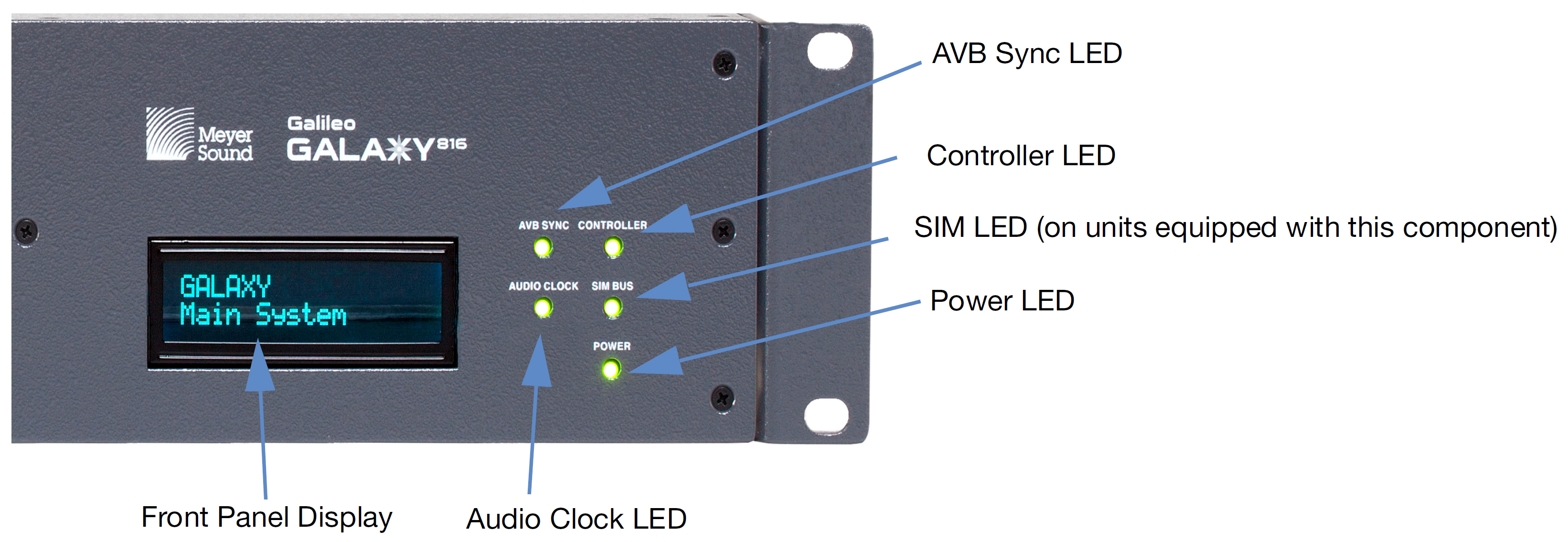
GALAXY processor front panel display
Front panel display: The front panel display provides the device name, current snapshot, device identity indicator, and other critical device notifications available on the GALAXY. Use the Front Panel Display Control in Compass to adjust the brightness and color.
Controller LED: Indicates activity when the GALAXY is connected to a client computer running the Compass control software.
SIM LED (on units equipped with this component): Indicates if the GALAXY is connected to a SIM audio analyzer.
Note
The GALAXY SIM Address must be set to a number in the range 0–14 (default is 10) in the SIM tab in Compass. It will then be available in the Switcher section of SIM under tabs 0–14, and can be configured to perform audio measurements.
Power LED: When lit, this LED indicates the GALAXY DC power supply is operating properly.
AVB sync LED: When lit, the LED indicates the GALAXY AVB media clock is locked.
Audio clock LED: When lit, the LED indicates the selected system clock (AVB, AES, or Internal) is locked.
GALAXY processor rear panels
The GALAXY 816 processor, the GALAXY 408 processor, and the GALAXY 816-AES3 processor have different rear panel connectors.
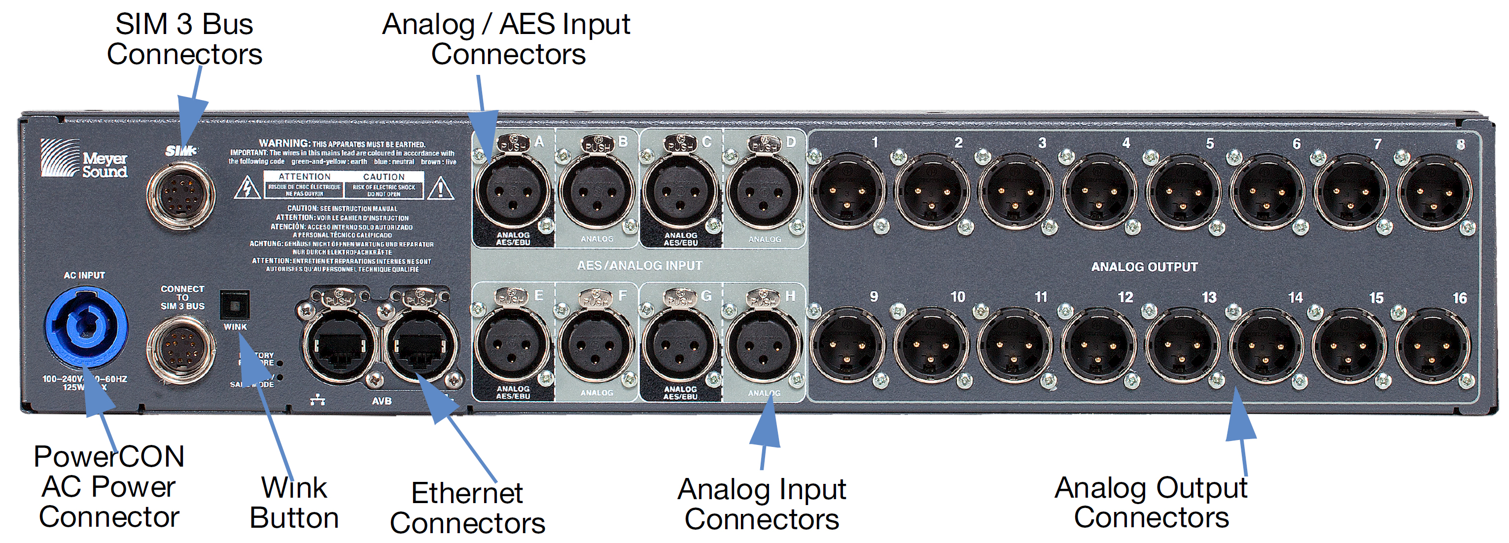
GALAXY 816 processor rear panel connectors
GALAXY 816 processor rear panel
The GALAXY 816 processor rear panel provides the following connectors:
PowerCON AC power connector: This locking connector mates with the provided AC power cable.
Caution
Make sure the AC power cable has the appropriate power plug on the other end for the area in which you will operate the GALAXY processor.
Note
The GALAXY processor incorporates Meyer Sound’s Intelligent AC power supply, which automatically adjusts to any line voltage worldwide, and provides soft turn-on and transient protection.
Ethernet connector: The two RJ-45 connectors can be used to attach the GALAXY processor to an AVB network to send audio signals through time-sensitive networks, and allow it to be controlled by Compass and/or Compass Go. Use a Gigabit Ethernet network cable (CAT5e or better). All primary network connections should be made to AVB port 1 on GALAXY processors. All secondary connections should be made to AVB port 2.
Analog / AES3 input connectors (A, C, E, G): Four XLR-3F input connectors accept either a standard line-level analog signal or an AES two-channel digital signal. In Compass (Settings > Input and Output), these inputs can be set to Analog, AES3 Left, or AES3 Right. Input Connectors B, D, F, and H can only be used as analog inputs. The GALAXY processor supports standard AES3 digital audio signals at discrete sample rates in the range of 20–216 kHz (see Input sample rates ).
Analog input connectors (B, D, F, H): Four XLR-3F input connectors accept standard line-level audio only. These inputs are typically paired with their corresponding input pairs (A, C, E, G) to receive two-channel audio signals. The analog-only inputs are disabled when their input pair is set to AES mode (i.e., when input A is set to AES mode, input B is disabled).
Analog output connectors (1–16): Sixteen XLR-3M connectors route audio to Meyer Sound self-powered loudspeakers or to amplifier channels driving passive systems.
SIM 3 Bus Connectors (for units equipped with these components): Connects to the SIM audio analyzer so the GALAXY’s inputs and outputs can be used as measurement points. A second SIM 3 bus port is provided to loop to additional GALAXY processors or to a SIM-3088 Line Switcher.
Wink Button: Pressing the Wink button on the rear of a GALAXY processor will cause the device to enter the Identify Mode, a bidirectional processor identification feature that helps users locate processors in multi-processor configurations. The front panel will flash, and Compass will show an indication on both the GALAXY processor’s Inventory tab and the Settings > Network tab of each processor (Settings tab). To exit Identify Mode, push the Wink button on the processor again or click on the Identify button on the Network tab in Compass.
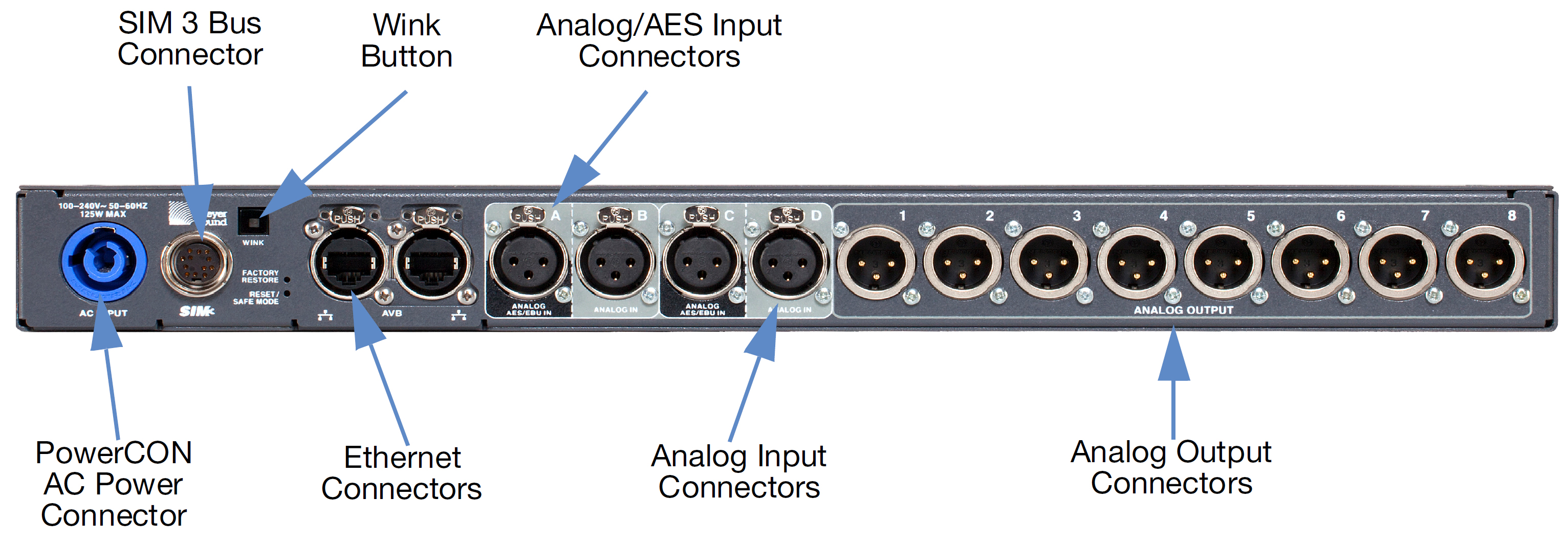
GALAXY 408 processor rear panel connectors
GALAXY 408 Processor Rear Panel
The GALAXY 408 processor rear panel provides the following connectors:
PowerCON AC power connector: This locking connector mates with the provided AC power cable.
Caution
Make sure the AC power cable has the appropriate power plug on the other end for the area in which you will operate the GALAXY.
Note
The GALAXY processor incorporates Meyer Sound’s Intelligent AC power supply, which automatically adjusts to any line voltage worldwide, and provides soft turn-on and transient protection.
Ethernet connector: The two RJ-45 connectors can be used to attach the GALAXY processor to an AVB network to send audio signals through time-sensitive networks, and allow it to be controlled by Compass and/or Compass Go. Use a Gigabit Ethernet network cable (CAT5e or better).
Analog /AES input connectors (A, C): Two XLR-3F input connectors accept either a standard line-level analog signal or an AES two-channel digital signal. In Compass (Settings > Input and Output), these inputs can be set to Analog, AES3 Left or AES3 Right. Input connectors B and D can only be used as analog inputs. The GALAXY processor supports standard AES3 digital audio signals at discrete sample rates in the range of 20–216 kHz (Input sample rates).
Analog input connectors (B, D): Two XLR-3F input connectors accept standard line-level audio only. These inputs are typically paired with their corresponding input pairs (A, C) to receive two-channel audio signals. The analog-only inputs are disabled when their input pair is set to AES mode (i.e., when input A is set to AES mode, input B is disabled).
Analog output connectors (1–8): Eight XLR-3M connectors route audio to Meyer Sound self-powered loudspeakers, or to amplifier channels driving passive systems.
SIM 3 bus connectors (for units equipped with these components): Connects to the SIM audio analyzer so the GALAXY’s inputs and outputs can be used as measurement points.
Wink button: Pressing the Wink button on the rear of a GALAXY processor will cause the device to enter the Identify Mode, a bidirectional processor identification feature that helps users locate processors in multi-processor configurations. The front panel will flash, and Compass will show an indication on both the GALAXY processor’s Inventory tab and the Settings>Network tab of each processor (Settings tab). To exit Identify Mode, push the Wink button on the processor again or click on the Identify button on the Network tab in Compass.
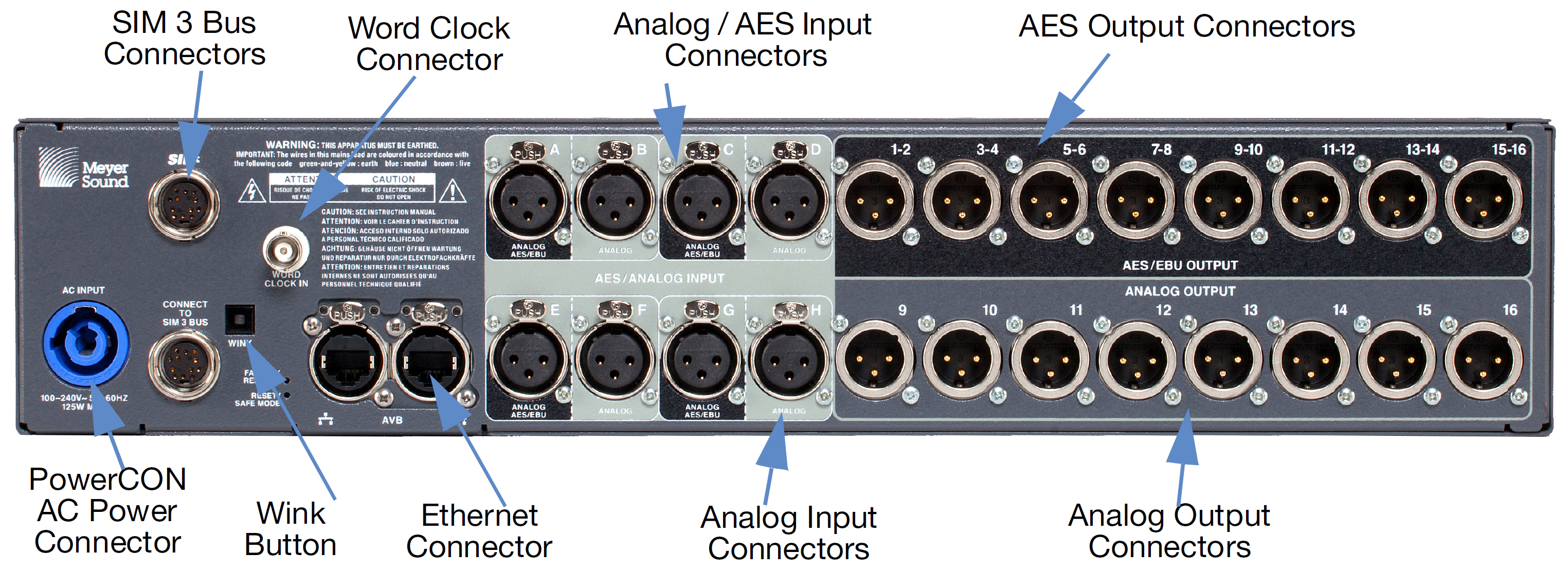
GALAXY 816-AES processor rear panel connectors
GALAXY 816-AES processor rear panel
The GALAXY 816-AES processor rear panel provides the following connectors:
PowerCON AC power connector: This locking connector mates with the provided AC power cable.
Caution
Make sure the AC power cable has the appropriate power plug on the other end for the area in which you will operate the GALAXY.
Note
The GALAXY incorporates Meyer Sound’s Intelligent AC power supply, which automatically adjusts to any line voltage worldwide, and provides soft turn-on and transient protection.
Ethernet connector: The two RJ-45 connectors can be used to attach the GALAXY processor to an AVB network to send audio signals through time-sensitive networks, and allow it to be controlled by Compass and/or Compass Go. Use a Giga-bit Ethernet network cable (CAT5e or better).
Analog / AES3 input connectors (A, C, E, G): Four XLR-3F input connectors accept either a standard line-level analog signal or an AES two-channel digital signal. In Compass (Settings > Input and Output), these inputs can be set to Analog or AES3 Left or AES3 Right. The GALAXY processor supports standard AES3 digital audio signals at discrete sample rates in the range of 20–216 kHz (see Input sample rates). Input connectors B, D, F, H can only be used as analog inputs.
Analog input connectors (B, D, F, H): Four XLR-3F input connectors accept standard line-level audio only. These inputs are typically paired with their corresponding input pairs (A, C, E, G) to receive two-channel audio signals. The analog-only inputs are disabled when their input pair is set to AES mode (i.e., when input A is set to AES mode, input B is disabled).
AES output connectors (1–16): The top row of eight XLR audio outputs for the GALAXY 816-AES3 provides 16 channels of AES3 digital outputs (two channels per output: 1–2, 3–4, etc.). Use only cables rated for AES signals to connect these outputs to the inputs of AES3 devices.
Analog output connectors (9–16): The bottom row has eight XLR-3M connectors to route audio to Meyer Sound self-powered loudspeakers or to amplifier channels driving passive systems. Any output processing applied to outputs 9–16 is mirrored in digital format on the appropriate AES3 output and on the corresponding analog output.
SIM 3 bus connectors (for units equipped with these components): Connects to the SIM audio analyzer so the GALAXY’s inputs and outputs can be used as measurement points. A second SIM 3 bus port is provided to loop an additional GALAXY or to a SIM-3088 line-level switcher.
Wink button: Pressing the Wink button on the rear of a GALAXY processor will cause the device to enter the Identify Mode, a bidirectional processor identification feature that helps users locate processors in multi-processor configurations. The front panel will flash, and Compass will show an indication on both the GALAXY processor’s Inventory tab and the Settings > Network tab of each processor (see Settings tab). To exit Identify Mode, push the Wink button on the processor again or click on the Identify button on the Network tab in Compass.
Power connector
The GALAXY uses a locking PowerCON® connector, as shown in the figure below, to provide AC voltage to the unit. Its internal switching power supply has a safety-agency-rated operating range of 100–264 V AC, 50/60 Hz.
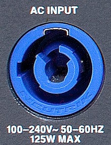
Locking PowerCON connector for AC power
Electrical safety issues!
Pay close attention to these important electrical and safety issues:
Caution
The PowerCON 20 connector should not be engaged or disengaged when under load or live. Disconnect the mains plug before disconnecting the power cord from the device.
GALAXY requires a grounded outlet. Always use a grounded outlet and plug.

SIM 3 connectors (for units equipped with these components)
The GALAXY rear panel includes a bus port for direct connection to the SIM audio analyzer. The GALAXY can then act as a line switcher for the analyzer and measure across any selection of inputs and outputs without additional patching.

GALAXY processor SIM 3 connectors: Connection to SIM and/or looping to other GALAXY processors (second looping connector not available on the GALAXY 408 processor)
The default bus address for the GALAXY processor is 10 and the available range is 0–14. The bus address is changed in Compass, (Settings > SIM). The GALAXY processor to SIM connection is auto-detected. The connection is indicated in SIM, in Compass, and with the SIM Bus LED on the GALAXY processor front panel.
A second SIM Bus connector is included on the GALAXY 816 processor and the GALAXY 816-AES processor rear panels. It can be used to connect to additional GALAXY processors or SIM-3088 Line Switchers.
Note
The GALAXY 408 processor does not have a looping SIM bus connector.
Client computer connection
The GALAXY’s RJ-45 port connects to a standard computer Ethernet port with Gigabit-capable (CAT5e or better) network cables. A Mac or Windows-based computer running Compass Control Software uses an Ethernet connection to control the unit remotely. Bi-directional communication between the GALAXY processor and Compass allows the user to change settings on either device and stay in sync.
To establish a connection between a single GALAXY processor and a computer, do the following:
Download the latest version of Compass Control software from the Meyer Sound website: meyersound.com/product/compass/#software
There is a registration procedure for first-time website users.
Install the Compass Control Software on a Mac or Windows-based computer.
Connect both the GALAXY processor and the Computer with Compass Control Software installed to the network switch.
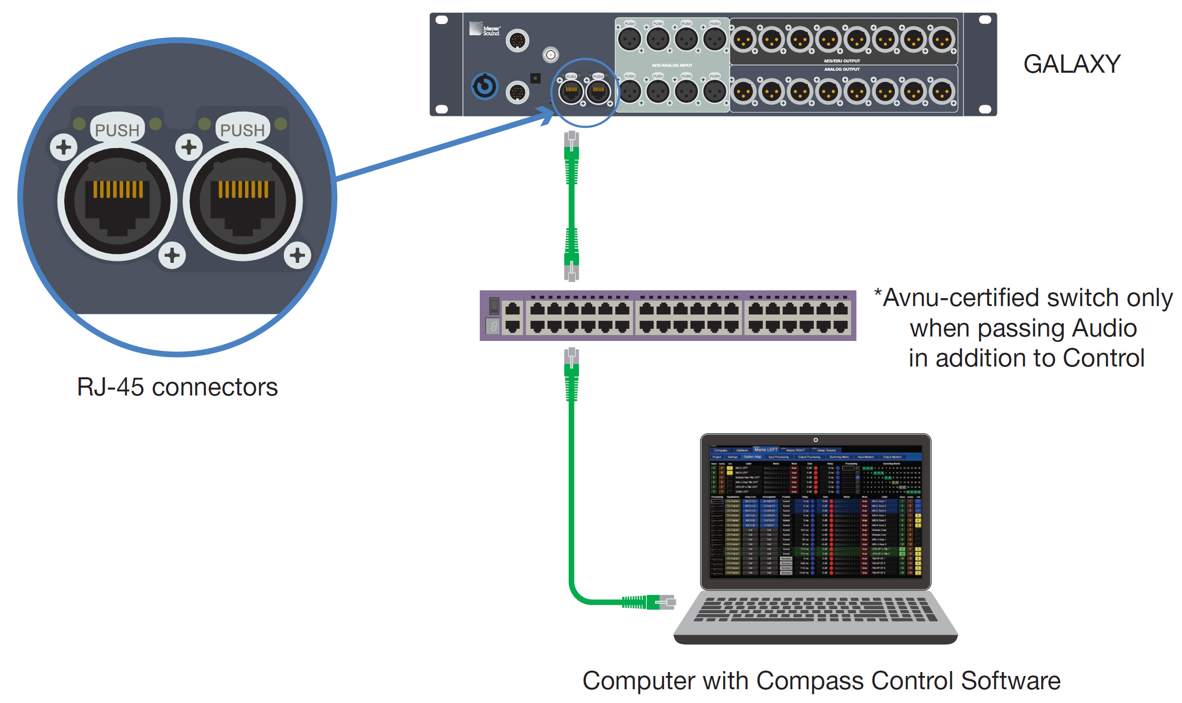
GALAXY processor and computer connected to a network switch
Apply power to the GALAXY processor by connecting the powerCON first, then the other end of the electrical cable.
Start the Compass application on the computer. The default user interface for Compass is shown below.
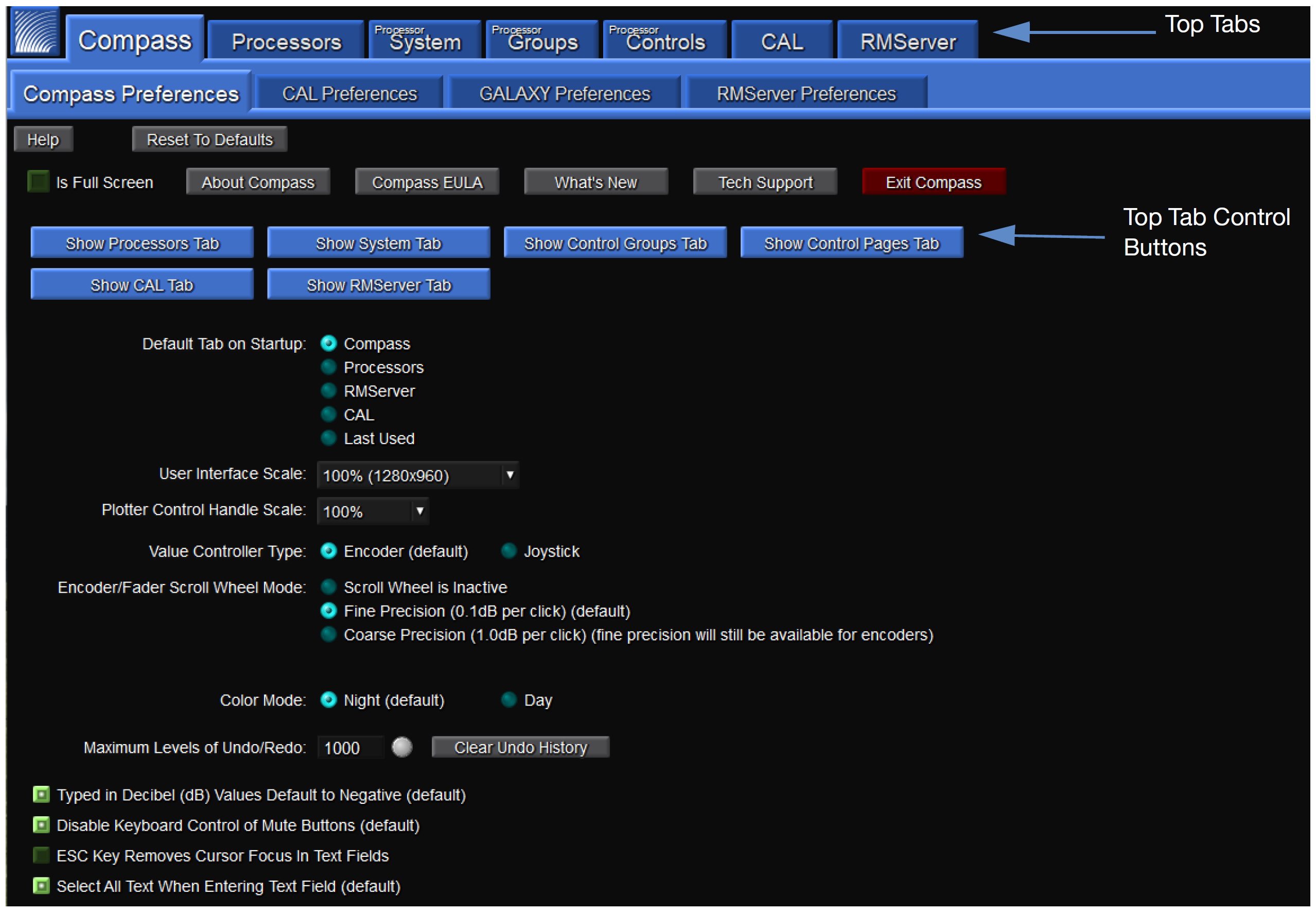
Compass default landing GUI
At this tab interface, the user can set a wide variety of preferences, including which tabs to show along the top of the Compass interface. Preferences for GALAXY processor may also be set at this level (see Setting preferences).
Make sure the Show Processors tab is selected. It will be blue when selected, and gray when deselected.
Click Processors, which then displays the Inventory tab. Click Find Devices to list the available GALAXY processors if they have not already been auto-discovered. The GALAXY processor connected in step 2 should automatically be listed. If it is not listed, verify that the switch is properly configured and all cabling is correct.
Click Connect for each of the processors to establish the client/server connection.
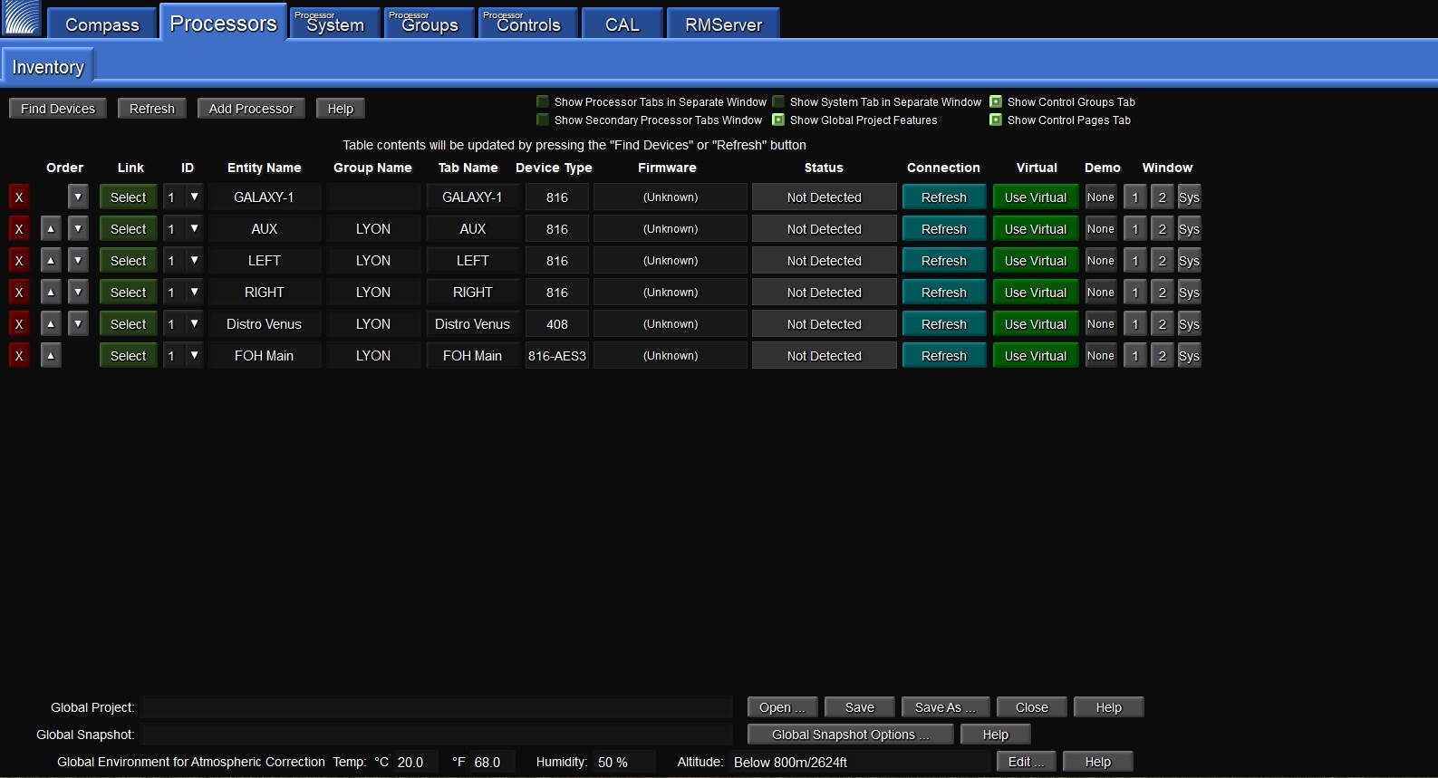
Processor tab landing window
Note
The client/server connection between GALAXY processors does not require setting IP Addresses. Compass uses IPv6 to connect to the processors. If the switches are properly configured and the cabling is correctly routed, Compass will automatically connect to the GALAXY processors.
If IPv6 addressing is unavailable, the GALAXY processors will default to IPv4 addresses as an alternate configuration method. If using a third-party controller that requires IPv4, GALAXY processors can be assigned IPv4 addresses. If assigning IPv4 addresses to a GALAXY processor, the Port 1 address and the Port 2 address cannot be the same.
GALAXY processors in a network configuration
The GALAXY processor includes two network ports for both AVB and control connections. Either port can be used to make single connections to a network. These ports take advantage of multiple industry-standard networking protocols enabling automatic fail-over. For more information about how to make AVB connections between devices, see the User Guide — Managing AVB Networks.
Controlling GALAXY processors with compass
Compass Control Software provides comprehensive control of GALAXY processors using an intuitive graphical user interface on a Mac® or Windows®-based computer. Compass provides control of all features on multiple units simultaneously. This chapter is a brief introduction to controlling the GALAXY processor via Compass and highlights some key GALAXY processor features.
Tip
Compass Go is an iPad application, a light version of the Compass Control software. It provides all the key functionalities of Compass with maximum mobility.
Note
Meyer Sound has developed videos to provide an overview of Compass Control Software; please visit meyersound.com/videos/#support
Meyer Sound Compass 4.3.6, Compass Go AM824, and their included GALAXY processor firmware are the last versions that support AM824 audio format. Compass 4.6 and above support AAF audio streams and CRF clock streams. GALAXY processors with different firmware will NOT be compatible with each other.
For most applications, Meyer Sound recommends upgrading GALAXY processors to the latest firmware, available for download at: meyersound.com/product/compass/
Setting preferences
Compass Control software allows users to set a wide variety of preferences, effectively customizing the interface to suit the needs of a particular application. If none of the Show Tab Controls, shown in the figure below, are selected, the Compass control window will only show the Preference setting tabs.
Each of these Preference tabs has a help button in the upper left corner that provides more detail about the various selectable options. There is also a button to Reset to Defaults if desired.
The GALAXY Preferences tab, shown in the figure below, has five sub tabs: Controls; Startup, Shutdown and Confirmation; Snapshot Recall; Select, Isolate and Linking; and Global Linking. The Controls tab has a drop-down menu to select delay units; all other preference options are indicated with square green buttons (on/off selections) and round blue buttons (either/or selections).
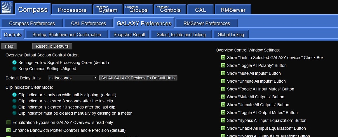
GALAXY Preferences tab
GALAXY processor user interface
To enter the GALAXY processor control area of Compass, select the Processors tab. The processors that have been automatically discovered will be listed here. If one or more processors are not listed, click the Find Devices button (upper-left). If the listed processors have a Status other than Available, click the Refresh button. Refresh only applies to devices already in the list after selecting Find Devices. When a processor is listed in the Inventory, the available GALAXY processor control tabs will appear next to the Inventory tab. The Refresh button next to Find Devices only applies to devices already in the list after selecting Find Devices.
Note
Find Devices uses mDNS protocol to discover devices. If “Find Devices” does not return any items, check to ensure mDNS is enabled.
Tip
Compass has context help available within the program. Look for a gray button labeled Help, or on the denser screens, a gray button with a small ? on it.
Meyer Sound has developed system example videos for the GALAXY processor that provide a good introductory overview. Visit: meyersound.com/videos/#support.
Inventory tab
Users can add, connect, and configure GALAXY processors within the Inventory tab. Select Show Global Project Features button at the top, which displays the options to save Global Projects, create Global Snapshots, and change the Global Environment settings. This tab provides the ability to:
Remove processors
Reorder the processors in the window
Link multiple processors together
See the detected version of GALAXY processor firmware
Connect/disconnect/refresh individual devices
Launch “Virtual” mode to work on a project without being connected to a real GALAXY processor (this feature also supports a demo mode with simulated meter values that sweep up and down)
Select whether a GALAXY processor is displayed in the main Compass window or a secondary window
Select whether or not the Systems tab will display a device’s settings.
If any of the processors are running firmware that is incompatible with the version of Compass, the firmware version will be displayed with an amber background rather than blue. The Galaxy firmware must be the version that corresponds with the Compass application being used. Either update the GALAXY processor firmware or use the version of Compass that corresponds to the GALAXY processor’s firmware.
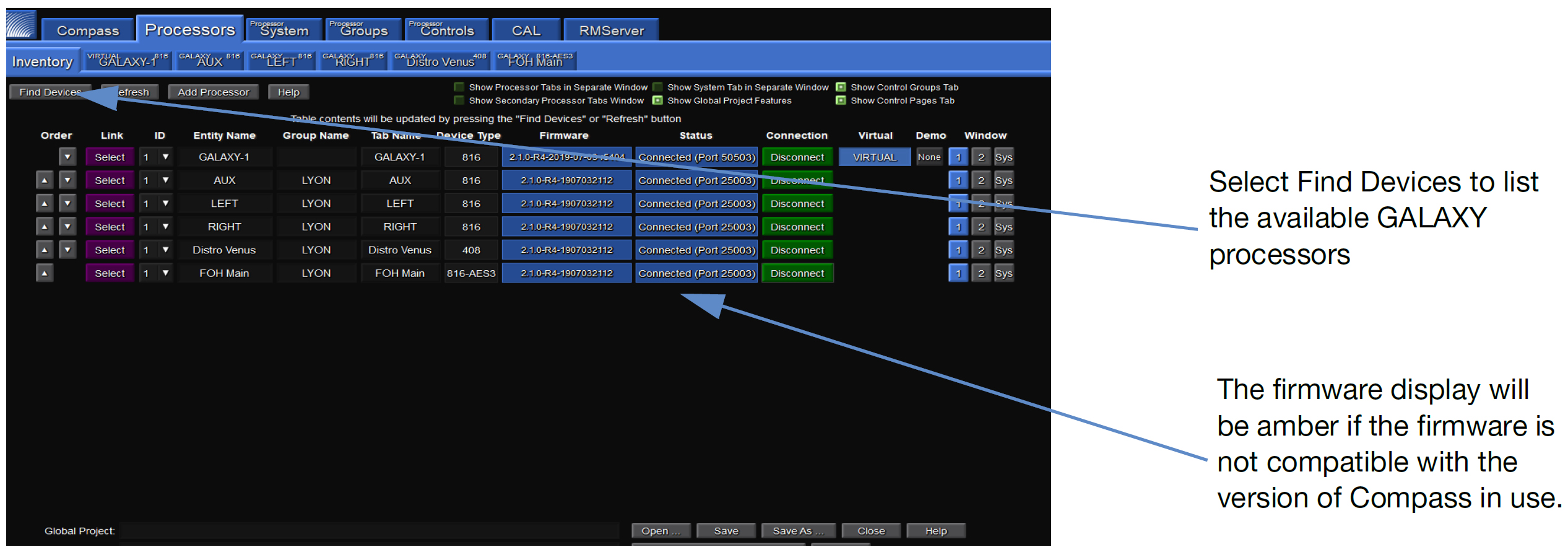
Inventory tab
Upgrading firmware
If firmware updating is required, see Network tab, or meyersound.com/videos/#support for a how-to video.
Individual processor control tab
Select the tab of a connected GALAXY processor at the top of the screen. The Overview tab will be displayed. Each processor tab has nine sub-tabs that provide controls to adjust the processor functions:
Project
Settings
Overview
Input Processing
Output Processing
Summing Matrix
Delay Matrix
Input Masters
Output Masters
A status bar is at the bottom of each GALAXY processor tab that includes:
Clock Status — Current clock status is displayed as locked or unlocked.
Project and Snapshot Controls — Current project and snapshot (see Projects tab) are displayed. The user can also save a project, update or create snapshots, and monitor whether or not a boot snapshot is enabled.
Channels Control — Three-row Channels bar allows a user to Select (link channels), Isolate (temporarily isolate a channel from other channels to which it is linked), and Link Groups (enable selection of multiple channels by selecting one) for all input and output channels.
Server Connection Status — Two small indicators in the bottom right will flash every couple of seconds when the server (processor) is properly connected. These lights signify that upload (ping) and download (pong) data transfers are happening.
Overview tab
The Overview tab is shown in the figure below. It provides a high-level view of GALAXY processor settings. The basic input and output settings can be modified by clicking, entering new values, or click-dragging controls. Many of the graphic elements are shortcuts to other tabs or open dialogs:
Input Processing
Summing Matrix
Output Processing
Product Integration Dialog
Atmospheric Correction Dialog
The dialog to adjust Product Integration settings can be accessed by clicking on the Product Integration indicator for each output. See Product Integration.
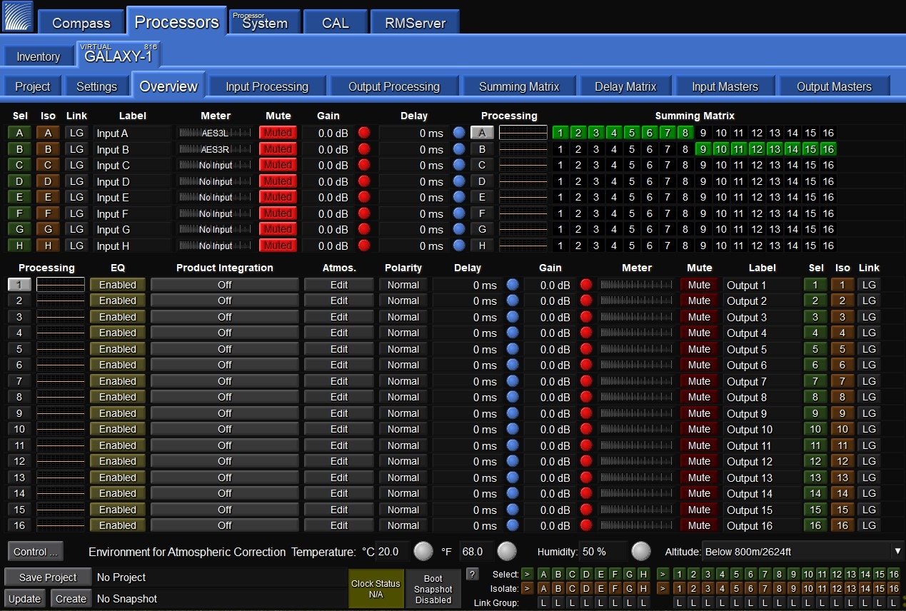
GALAXY Processor User Interface in Compass Control Software
Projects tab
GALAXY processor project files can be saved by the Compass Control software to the client computer. Project files contain all of the Snapshots stored in the processor and all of the current control point values.
A Snapshot contains all of the control point values of a processor when a Snapshot is created. The GALAXY processor can store up to 255 Snapshots in the Snapshot Library.
The relationship between the GALAXY processor and Compass is server/client: the GALAXY processor is the server, Compass the client. When a computer is connected to a GALAXY processor, the Compass Control Software reads and displays the current state of all control points and the list of Snapshots stored in the GALAXY processor. However, opening another GALAXY Project file (stored on the computer) will overwrite the Snapshot Library and, if selected, the current device settings.
Compass also has a Virtual mode that is selectable from the Inventory tab. This mode allows a user to work on a project file without being connected to real GALAXY processor hardware. In effect, Compass is connecting to a virtual GALAXY server.
Caution
Opening a project file in the Compass Control Software when the computer is connected to a GALAXY processor overwrites all stored Snapshots and the current device settings of the GALAXY processor if Load Device Settings is selected when the GALAXY Project is opened. To merge snapshots from another Project file into the current Snapshot library in a GALAXY processor, use the Merge Project option from the Project tab (click the More>> button for this option to appear).
Tip
Use Compass Control software to store GALAXY processor control point values as a Snapshot in the GALAXY processor. The Snapshot Library is stored as a Project on the client computer and can later be reloaded into the GALAXY processor.
Note
Firmware updates do not affect Snapshots or control point values. To restore factory defaults, see Network tab.
Settings tab
The Settings tab has eight sub-tabs: Network, Input and Output, SIM, Environment, Access, Low-Mid Beam Control, Link Groups, and Log.
Input and output
Under the Settings tab, the user can configure input channel types, AVB Control Mode, Channel Selection, System Clock, AES Output Clock (AES Version Only, see Clocking), and input/output voltage ranges.
Input Channel Types are configured individually to either Analog, AES3, or AVB. For the GALAXY 816 processor and the GALAXY 816-AES processor, AES connections are made to ports A, C, E, G; the companion ports B, D, F, and H must be left unconnected. For the GALAXY 408 processor, AES connections are made to connectors A and C; the companion ports B and D must be left unconnected. Compass indicates which XLR connectors are utilized based on the input channel’s analog or AES3 status.
AVB Control Mode: network digital source signals may be connected to the AVB/Network port connectors (labeled 1 and 2) on the GALAXY processor rear panel. These connectors allow for the usage of Milan-compliant AAF streams for Audio (see the AVB Networking Guide, available at https://meyersound.com/documents).
Milan-compliant AAF and CRF streams are supported for Clocking. There are two modes: Internal and External. Internal Mode allows the GALAXY Internal AVB connection manager to control all AVB Input Streams. External Mode disables the GALAXY Internal AVB connection manager and allows an external Milan controller to connect the AVB streams.
Only one signal type can be selected for each input. Outputs from available GALAXY processors will populate the AVB browser when that device is selected from the available Devices list. The Group can be selected from the Group selection menu. Connections can be established and disconnected.
AVB Stream Info: to access the AVB Stream Info, press the “Info” button on the Input and Output tab GUI, opening a secondary window. The left side lists data about the Primary input source and the right side lists data about the Secondary input source.
Channel Selection: “selected” channels are linked. Changes made to one selected channel will be made to all other selected channels of the same type (input or output) in a device. Depending on the Global Link Preferences, channels on other devices may be affected as well. Use Link Groups (Link Groups) to quickly select or deselect multiple channels. Selected channels have a green background.
AVB Output Settings: the Default Presentation Time can be set for each GALAXY processor on the Network from 0.250–2 ms; the default value is 2 ms. Reducing the value of the Presentation Time will lower the latency of the AVB stream output from a talker to a listener. The MSRP Accumulated Latency will display the worst case time through the network, and can be used as a reference of how low the Default Presentation Time can be set. In some cases, it is desirable to use a lower latency, which can be accomplished by reducing the Default Presentation Time. The Default Presentation Time should never be set lower than the MSRP Accumulated Latency.
For more information about network configurations and a discussion about Presentation Time, see the AVB Network Guide (PN 05.010.541.01) available at meyersound.com/documents
System Clock: the GALAXY System Clock can be configured to either the Internal Clock, an AVB Clock CRF, an AES input, or an AVB AAF Input. For the GALAXY 816-AES processor, the Word Clock (BNC connector) can also be configured as the GALAXY processor media clock. This option allows the GALAXY 816-AES3 processor to be synchronized to an external source for both the system clock and AES output clock, at 48 or 96 kHz. AES allows discrete values in the range from 20–216 kHz (see Input sample rates).
Note
“Media clock” is the common terminology used in the Milan specification. Within the GALAXY processor Settings: Input and Output tab, the media clock choice is selected under the “System Clock: Clock Mode” pull-down menu.
When an incoming 96 kHz AES signal is selected as a clock source under the system clock pull-down tab, disable the Asynchronous AES sample rate converters to reduce latency through the system. These ASRC converters are only available on the AES inputs and only required when the incoming AES signal does not match the 96 kHz internal clock frequency to within +/- 100 ppm.
Caution
When AES ASRC is enabled on an input, the clocking data associated with that input is removed by the GALAXY processor, and that input may not be used as a valid System Clock.
All AVB inputs must be synchronized to a common media clock, and the clock must originate from one of the incoming AVB sources and cannot be daisy-chained (see Common media clock for multiple interconnected GALAXY processors Common media clock for multiple interconnected GALAXY processors).
Input/Output Voltage Range: allows the user to set analog channels to either +16 dBu or +26 dBu. These settings only apply to analog channels.
Network tab
The Network tab lists the following GALAXY processor options:
Device Type
Device Name (editable)
Entity Name
Group Name (editable)
Serial Number
IPv6 Address
IPv4 Address (editable)
MAC Address
Front Panel LCD Display options (editable)
Color and Brightness
Date and Time (editable)
Operating Mode Indicator
Soft Reboot Options
Upload Firmware options
Edit Network Settings options
Firmware may be uploaded from this page by following these steps:
Reboot the GALAXY processor into Recovery Mode, enabling the Upload Firmware, and Upload Firmware to all GALAXY devices.
Firmware can be uploaded to one or all connected processors by clicking Upload Firmware or Upload Firmware to all GALAXY devices.
Select either the
.bluehornFirmwareor.galaxyFirmwarefile that matches the GALAXY processor type from the Compass Application folder.The firmware will begin uploading when OPEN is clicked. The progress is indicated in a pop-up window, which can be closed while the upload continues. While the firmware upload is in progress, the GALAXY processor will not pass audio and the tab color will change to amber.
The time of the GALAXY processor may be set to a specific time or to the connected computer’s time using the Set Device Time button. In this dialogue, there is an option to set just one, or all connected GALAXY processors to the new time.
The GALAXY front panel LCD color can be adjusted for brightness and color. The available options are Green, Blue, Cyan, Yellow and Magenta. The Front panel display can be set to Normal, Dim, and Bright.
There is also an option to reboot to the factory defaults by selecting the Reboot with Factory Defaults button on this page.
Identify button
Pressing the Wink button on the rear of a GALAXY processor will cause the device to enter the Identify Mode, a bidirectional identification feature. The front panel will flash, and Compass will show an indication on both the GALAXY processor’s Inventory tab and the Settings > Network tab (Identify button will flash) of each processor. To exit Identify Mode, push the Wink button on the processor again, or click on the Identify button on the Network tab in Compass.
Tip
Identifying a GALAXY processor and then naming that processor helps make identification easier.
SIM tab
Under the SIM tab, the user may configure settings related to the SIM Audio Analyzer. There are two probe points (SIM Console and SIM Processor) that can each be set to any of the five possible probe selections: Input Post Source Select, Input Post Processing, Output Post Matrix, Output Post EQ, and Output Post Processing.
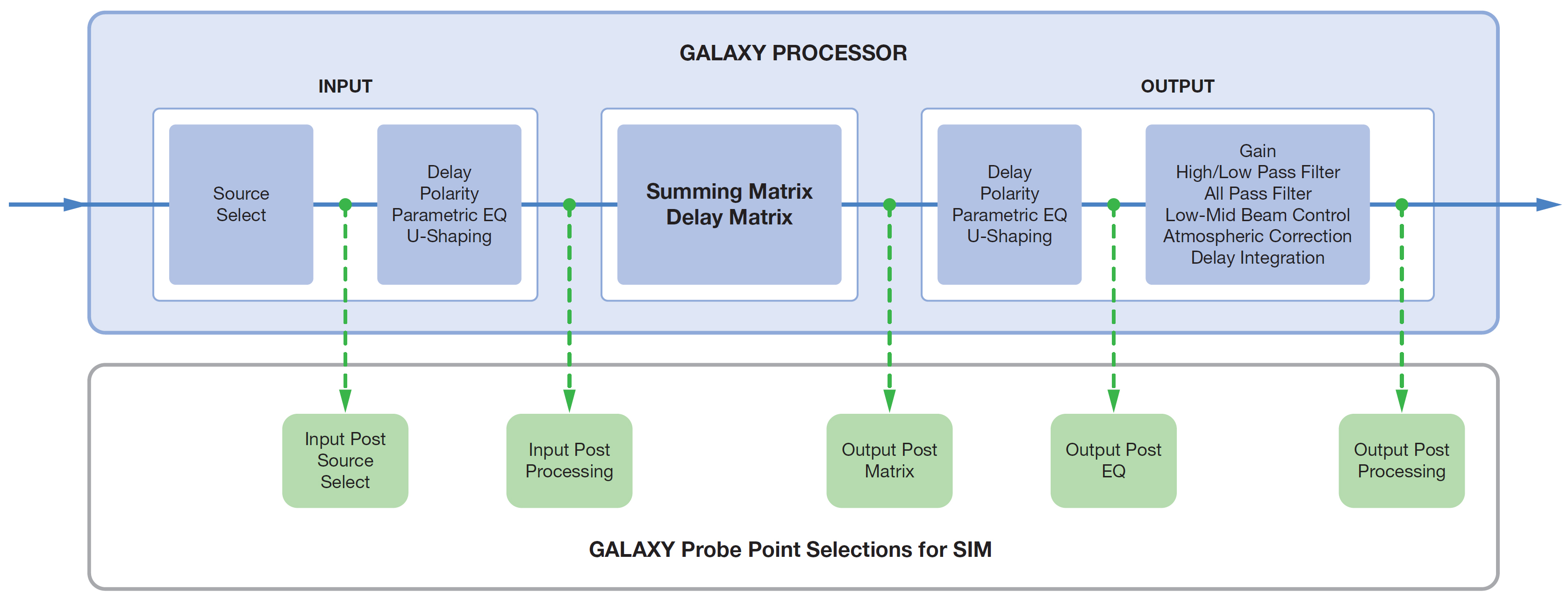
Possible GALAXY processor SIM probe point selections
Environment
The Environment tab is one place to adjust the global values for temperature, humidity, and altitude. These settings, in conjunction with the parameters of each output channel (Atmospheric Gain and Distance), recall filter settings to compensate for high-frequency attenuation due to propagation loss through air. There is also a square on/off toggle button to select whether or not to link Correction Distance and Atmospheric Gain Factor settings across all output channels.
Access
The Access tab allows a user to control access to various GALAXY processor settings, confining access to particular controls for different users based on their role settings. These settings apply to situations such as permanent installations where multiple users have access, or situations where various parts of show design are divided amongst several people.
Low-Mid Beam Control
Link Groups
Link Groups allows for the editing of multiple channels simultaneously. The Link Group index buttons are blue when enabled, yellow when bypassed, and gray when not in use.
Log
The Log tab displays a date and time-stamped running record of a GALAXY processor’s operation. This display is a subset of all log data (includes client level messages). For a more detailed log history (that might help Meyer Sound Tech Support, for example, in a debug situation), use the Save System Logs button under the Settings tab. Clicking this button will save more information, including kernel logs and operating system details.
Input Processing tab
The display under the Input Processing tab, shown in the figure below, is divided into two sections. The upper part provides a Plotter display, where a user can visualize input channel equalization. The plotter plots gain (left vertical axis) and phase (right vertical axis) against frequency (x-axis). If gain and phase happen to align, that situation is purely coincidental. Two select buttons on the top control whether the display is dual (two channels simultaneously) and whether or not to show the settings control mini tabs. When selected, three mini tabs will appear to the right of the display: Plotter, Handles, and Response:
The Plotter mini tab provides some axis control. It also allows control of the number and arrangement of plotters, and what to display or hide. More than one EQ plot may be shown at a time by selecting “Multiple” under the Plotter mini tab.
The Handles mini tab controls the display or removal of EQ handles in the plotter.
The Response mini tab controls whether to display or hide specific response curves in the plotter.
All of these mini tabs can be hidden from view by using the right/left blue arrows on the bottom right of the mini tab.
The bottom part of the tab displays the input processing control. This part of the display may be minimized by clicking the up/down arrow under the Plotter display. Within the control area under the Input Processing tab, a user may select the processing desired for each input. Possible processing includes Gain, Delay, 5-band Parametric EQ, and 5-band U-Shaping EQ.
This window has three tabs near the bottom left of the screen to control the processing parameters: Channel Settings, Parametric, and U-Shaping.
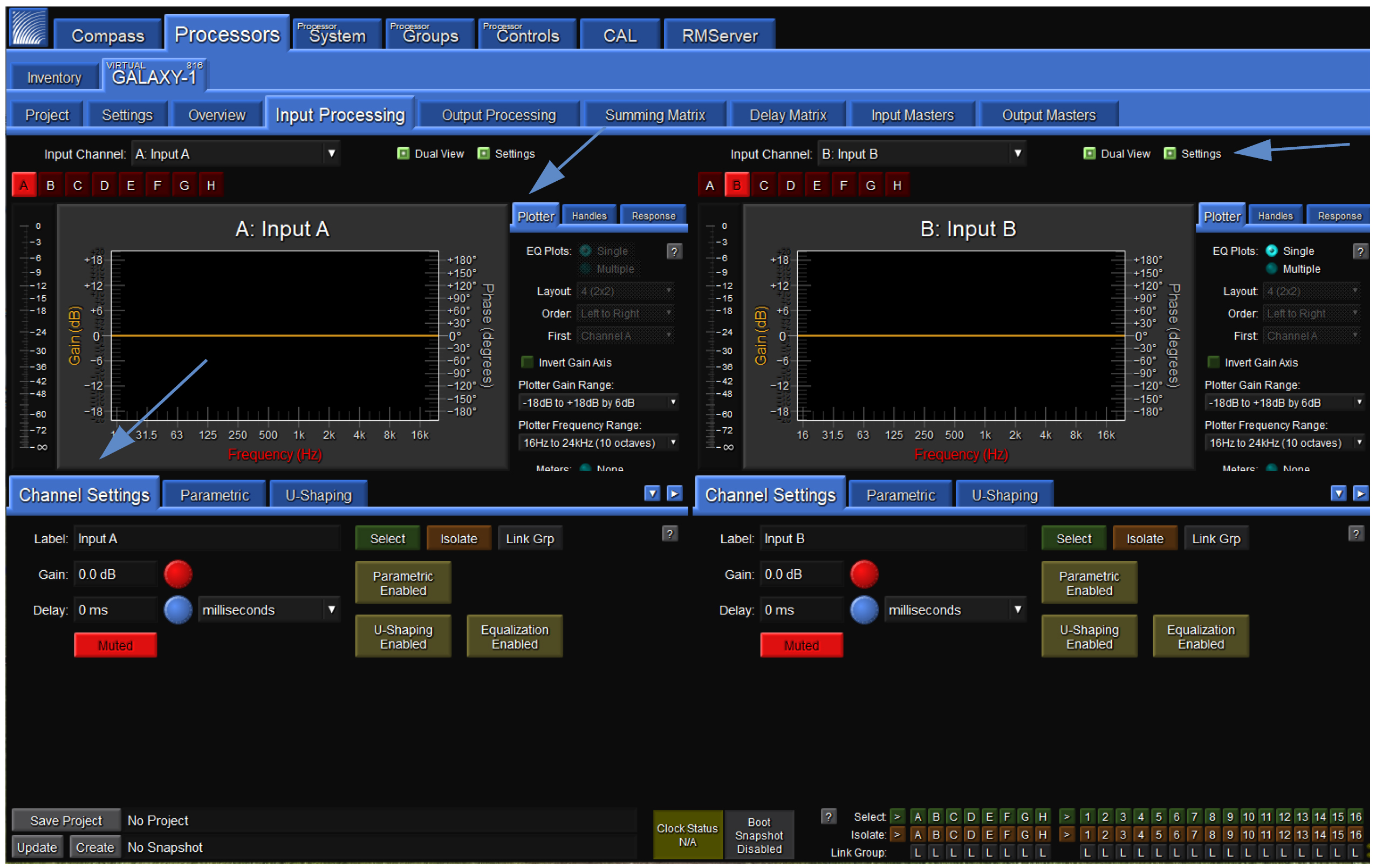
Processor > Input Processing tab
Channel Settings tab (Input Processing tab)
Under the Channel Settings tab in Input Processing, the user can set a Label, Gain value, Delay Value, Mute the Channel, and enable or bypass Parametric, U-Shaping, and/or all EQ for a particular input channel. Select the Input Channel to control via the drop-down menu or individual alphabetic channel buttons (e.g., A-H for a GALAXY 816 processor) above the plotter display.
The Label widget allows a user to enter a short text description of a Channel, Array Group, or Link Group. It is for informational purposes only.
The Gain widget lets the user increase or decrease the signal level by decibels (dB). The default assumes negative gain values. Entering any integer will result in the gain being set to the negative of that integer (e.g., “3” becomes -3 dB gain). (The default may be changed to positive gain values in the Compass Preferences tab.)
The Delay widget allows the user to add a delay in various units to an input channel or matrix input signal. The range is 0–500 ms.
Clicking the input channel Mute button prevents any signal from being sent to the matrix.
Clicking the Select button causes this channel to be linked to other input channels that are also selected. Changes made to one selected channel will be made to all other selected channels of the same type (input or output) of a device. Depending on the Global Linking Preferences, channels on other devices may be affected as well. Use Link Groups to quickly select or deselect multiple channels. Selected channels have a green background.
Use the Isolate button to temporarily isolate a channel from other channels to which it is linked. Isolating a channel will change its background color to amber.
Use the Link Groups button to edit multiple channels simultaneously. The Link Groups tab is also accessible from this pop-up menu. The link group to which a channel belongs is indicated by the number next to LG. Link group index buttons are blue when enabled, yellow when bypassed, and gray when not in use. Channels in active link groups may have a blue background, depending on the Link Groups and Selects mode.
The Parametric EQ Bypass button allows the user to bypass Parametric EQ for an input channel without affecting the individual Parametric Band Bypass settings.
The U-Shaping Bypass button allows the user to bypass the U-Shaping EQ filter on a GALAXY processor input channel.
The EQ Bypass button allows the user to bypass all input equalization filters while leaving filter-specific EQ bypass settings alone.
Parametric (Input Processing tab)
Parametric controls may be set via a tab in the lower half of the Input Processing tab shown in the figure below. Input Parametric EQ has 5 bands. Each band has four settings:
Bypass — Allows the user to bypass an individual parametric EQ band for that channel.
Frequency — Allows the user to adjust the central frequency of a parametric EQ band. The Frequency range is 10 Hz – 20 kHz. When entering a value, the Hz suffix is optional. A value can be entered in a number of ways. For example, 1500 Hz may be entered as 1.5 k, 1k5, and 1500.
Bandwidth — Sets the range of frequencies that are affected by band gain changes. The Bandwidth range is 0.1–2.0. When the Bandwidth is “1,” the handles span one octave. Setting it to “2” means the handles span two octaves.
Gain — Allows the user to adjust the gain of a parametric EQ band. The Gain range is -18 dB to +18 dB.

Processor > Input Processing > Parametric and U-Shaping tabs
U-shaping (Input Processing tab)
Controls for U-shaping are located within a tab also in the lower half of the Input Processing tab. The U-Shaping filter has five gain bands and four frequency breakpoints.
Each gain band may be individually set within the U-Shaping tab. The default assumes negative gain values (e.g., entering a “3” into the number box will result in a gain of -3 dB). This default setting may be changed to positive gain values via the Compass Preferences tab (Setting preferences).
Each of the four frequency breakpoints may also be set within the U-Shaping tab. The numerical input accepts a variety of format options. For example, 1500 Hz may be entered as 1.5 k, 1k5, and 1500. Entering “Hz” is optional.
The Slope settings are controlled via a pull-down menu. The two slopes on the left offer 6, 12, 18, 24, 30, 36, or 48 dB/octave. The two on the right do not have the 48 dB option.
The Bypass button allows U-shaping to be bypassed without affecting the settings.
Output Processing tab
Similar to the Input Processing tab, the Output Processing tab, shown in the figure below, allows a user to visualize and edit output channel equalization and settings. The upper part of the display is the plotter, the lower part the control. The plotter plots gain (left vertical axis) and phase (right vertical axis) against frequency (x-axis). If gain and phase happen to align, that situation is purely coincidental. Two select buttons on the top control whether the display is dual (two channels simultaneously) and whether or not to show the settings control mini tabs. When selected, three mini tabs will appear to the right of the display: Plotter, Handles, and Response:
The Plotter mini tab allows control of the number and arrangement of plotters, what to display or hide, and provides some axis control.
The Handles mini tab controls the display or removal of EQ handles in the plotter.
The Response mini tab controls whether to display or hide specific response curves in the plotter.
The mini tabs can be hidden from view by using the right/left blue arrows on the bottom right of the mini tab.
The bottom part of the display enables output processing control. This part of the display may be minimized by clicking on the up/down arrow under the Plotter display. Within the control area under the Output Processing tab, a user may select the processing desired for each input. Possible processing includes Gain, Delay, Polarity reversal, 10-band Parametric EQ,
5-band U-Shaping EQ, Low-Mid Beam Control, atmospheric correction, simultaneous high- and low-pass filtering and All Pass filtering.
This window has four tabs near the bottom left of the screen to control the processing parameters: Channel Settings, Parametric, U-Shaping, and All Pass.
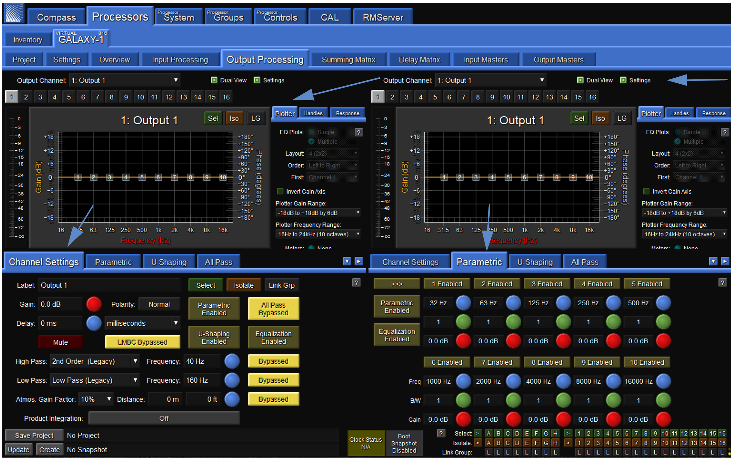
Processor > Output Processing > Channel Settings and Parametric tabs
Channel Settings tab (Output Processing tab)
Under the Channel Settingstab in Output Processing the user can set a Label, Gain value, Delay Value, Mute the Channel, and enable or bypass Parametric, U-Shaping, All Pass Filtering, and/or all EQ for a particular output channel. Select the Output Channel to control via the drop-down menu or individual alphabetic channel buttons above the plotter display.
The Label widget allows a user to enter a short text description of a Channel, Array Group, or Link Group. It is for informational purposes only.
The Gain widget lets the user increase or decrease the signal level by decibels (dB). The default assumes negative gain values. Entering any integer will result in the gain being set to the negative of that integer (e.g., “3” becomes -3 dB gain). (Default may be changed to positive gain values on the Compass Preferences tab.)
The Delay widget allows the user to add a delay (0–2000 ms) in various units to an output channel signal.
The Polarity button allows the user to change the polarity of each output channel from Normal (Pin 2 positive relative to Pin 3) to Reversed Polarity (Pin 3 positive relative to Pin 2).
Clicking the Mute button prevents any signal from being sent to the output of the channel.
Clicking the Select button causes this channel to be linked to other output channels that are also selected. Changes made to one selected channel will be made to all other selected channels of the same type (input or output) in a processor. These changes are relative by default. If channel 1 delay is 0 ms and channel 2 delay is 10 ms, when they are linked and channel 1 delay is changed to 5 ms, channel 2 delay will be 15 ms. Hold ALT while pressing ENTER for absolute values. To change default preference, change settings on this tab: Compass > GALAXY Preferences > Select, Isolate and Linking. Depending on the Global Linking Preferences, channels on other devices may be affected as well. Use Link Groups to quickly select or deselect multiple channels. Selected channels have a green background.
Use the Isolate button to temporarily isolate a channel from other channels to which it is linked. Isolating a channel will change its background color to amber.
Use the Link Groups button to edit multiple channels simultaneously. The Link Groups tab is also accessible from this pull-down menu. The Link Group to which a channel belongs is indicated by the number next to LG. Link Group index buttons are blue when enabled, yellow when bypassed, and gray when not in use. Channels in active link groups may have a blue background, depending on the Link Groups and Selects mode.
The LMBC Bypass button is a shortcut to the Low-Mid Beam Control tab (see Low-Mid Beam Control (LMBC)).
The Parametric EQ Bypass button allows the user to bypass Parametric EQ for an output channel without affecting the individual Parametric Band Bypass settings.
The U-Shaping Bypass button allows the user to bypass the U-Shaping EQ filter on a GALAXY processor output channel.
The EQ Bypass button allows the user to bypass all output Equalization filters while leaving filter-specific EQ bypass settings alone. Product Integration and Atmospheric Correction settings are not bypassed with this control.
The High Pass Filter widget allows the user to select a high-pass filter for the output channels from nine different options.
The Low Pass Filter widget allows the user to select a low-pass filter for the output channels from eight different options.
The Atmospheric Correction widget allows the user to apply equalization to the higher frequencies of a signal that might be affected by the natural environment. There are also widgets to enter the distance between the loudspeakers and the listening area. The attenuation of higher frequencies in the air varies with temperature, humidity, and altitude. There are Global Environment settings that allow a user to adjust for a particular natural environment (see Environment and Atmospheric correction).
The Product Integration button allows a user to turn on product integration for a particular channel (see ???).
Parametric (Output Processing tab)
Parametric controls may be set via a tab in the lower half of the Output Processing tab. Output Parametric EQ has 10 bands. Each band has four settings:
Bypass — Allows the user to bypass an individual parametric EQ band for that channel.
Frequency — Allows the user to adjust the central frequency of a parametric EQ band. The Frequency range is 10 Hz – 20 kHz. When entering a value, the Hz suffix is optional. A value can be entered in a number of ways. For example, 1500 Hz may be entered as 1.5 k, 1k5, and 1500.
Bandwidth — Sets the range of frequencies that are affected by band gain changes. The Bandwidth range is 0.1–2.0. When the Bandwidth is “1,” the handles span one octave. Setting it to “2” means the handles span two octaves.
Gain — Allows the user to adjust the gain of a parametric EQ band. The gain range is -18 dB to +18 dB.
U-shaping (Output Processing tab)
Controls for U-shaping are located within a tab also in the lower half of the Output Processing tab. The U-Shaping filter has five gain bands and four frequency breakpoints.
Each gain band may be individually set within the U-Shaping tab. The default assumes negative gain values (e.g., entering a “3” into the number box will result in a gain of -3 dB). This default setting may be changed to positive gain values via the Compass Preferences tab (Setting preferences).
Each of the four frequency breakpoints may also be set within the U-Shaping tab. The numerical input accepts a variety of format options. For example, 1500 Hz may be entered as 1.5 k, 1k5, and 1500. Entering “Hz” is optional.
The Slope settings are controlled via a pull-down menu. The two slopes on the left offer 6, 12, 18, 24, 30, 36, or 48 dB/octave. The two on the right do not have the 48 dB option.
The Bypass button allows the U-shaping to be bypassed without affecting the settings.
All Pass Filters tab (Output Processing tab)
The All Pass Filter tab, shown in the figure below, allows the user to engage up to three second-order all-pass filters, changing the phase relationship between various frequencies, while not altering the gain at any frequency. Adding all-pass filters is different than adding pure delay. While delay introduces the same amount of delay to all frequencies, all-pass filters introduce different amounts of delay at different frequencies. These filters are described by the frequency at which the phase shift is 180°.
Within this tab, the user may set the center frequency of the all-pass filter (frequency at which the phase shift crosses 180°) and the bandwidth Q of the filter. The lower the Q, the greater the bandwidth.
All Pass filters will alter the native phase response of the loudspeaker. This alteration may degrade performance and should only be used by experienced operators.
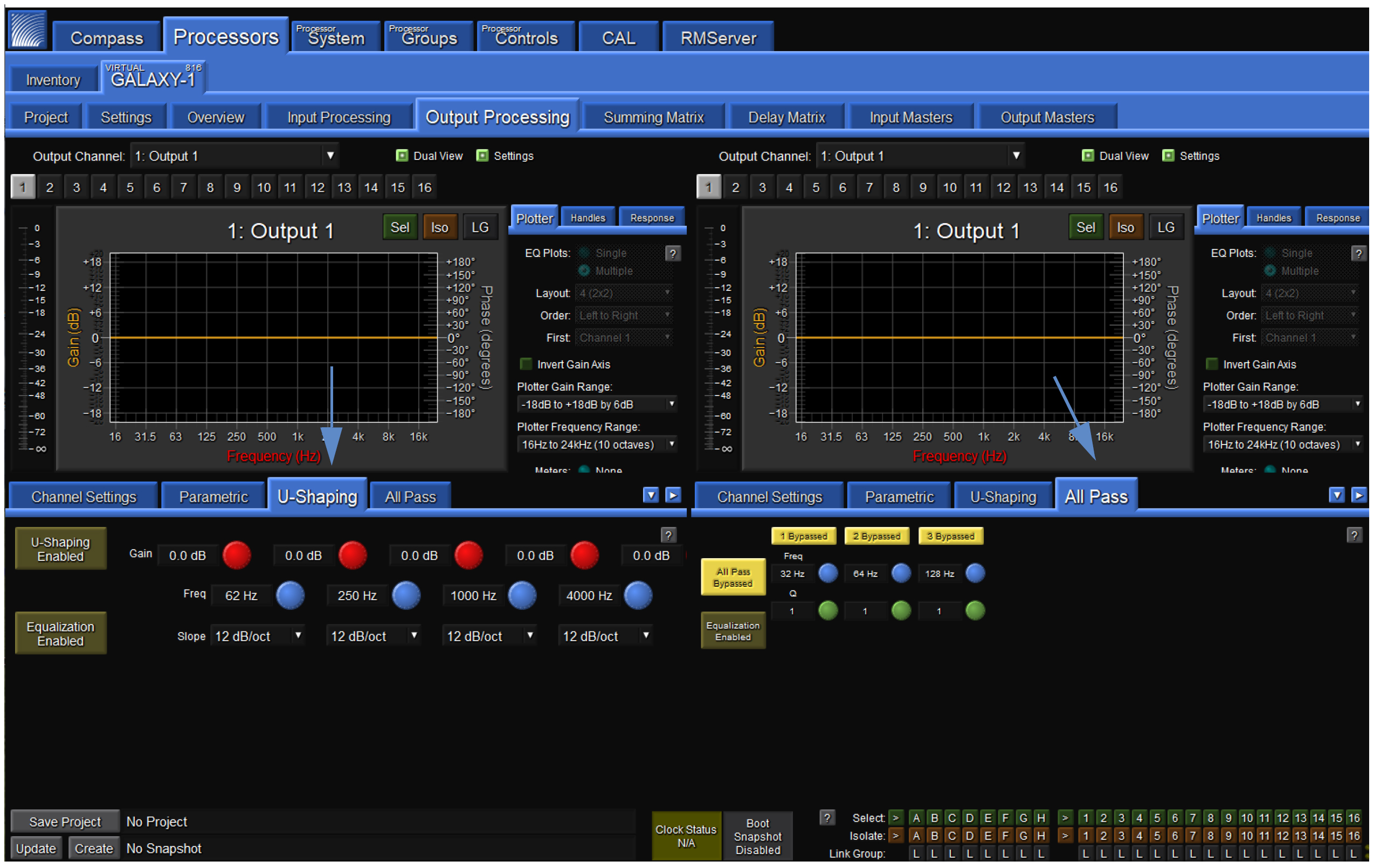
Processor > Output Processing > U-Shaping and All Pass tabs
Summing Matrix tab
The Summing Matrix, shown in the figure below, allows the user to route inputs to outputs within the processor. A maximum of 232 out of 512 connections between input channels and output channels (cross-points) can be made in the Summing Matrix tab. Each input channel can be level adjusted independently to individual output channels.
The Show Matrix Rows drop-down selects which inputs are displayed for routing. Inputs are the eight channels of processed inputs. Matrix In 9-16, 17-24, and 25-32 are only used for unprocessed AVB inputs.
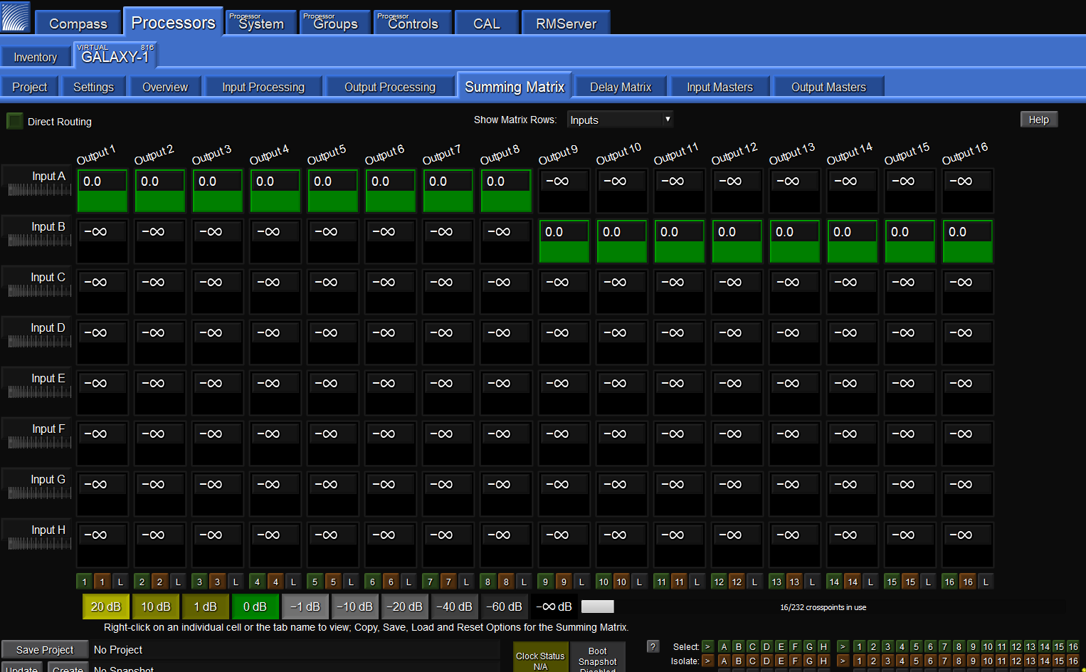
Processor > Summing Matrix tab
Matrix modes: Summing or Direct Routing
The Summing Matrix has two modes: Summing or Direct Routing. The mode is controllable via a select button at the top left of the Summing Matrix display window.
Summing is the default setting that allows the user to route multiple inputs to single or multiple outputs. When the Direct Routing button is selected, only one of the input channels may be assigned to one output.
Summing matrix operation
In both modes, the gain value for any matrix cross-point can be adjusted. The gain range is -90 dB to +20 dB, where -90 dB equals -infinity dB.
To select which group of 8 inputs to view at any one time, use the Show Matrix Rows drop-down menu above the matrix display in the middle of the screen.
The lower right-hand corner has a display indicating the number of cross-points in use. Of the 512 possible cross-points, 232 can be set simultaneously.
Color coding
Negative gain values scale from light gray to dark gray. Positive gain values scale from dark olive to light olive. There is a color legend below the matrix.
Delay Matrix tab
Delay times may be assigned to each matrix cross-point in the Delay Matrix tab shown in the figure below. Any delay values implemented here are independent of delay times included in the input or output processing blocks.
Each input channel can be assigned a time value independently to individual output channels.
To select which group of 8 inputs to view at any one time, use the Show Matrix Rows drop-down menu above the matrix display in the middle of the screen.
Delay can be bypassed by pressing the small button labeled “B” next to the delay time for each cross-point. Numeric delay values can be input for any matrix cross-point between 0–2000 ms.
The units for all channels may be set at the bottom right corner of this window.
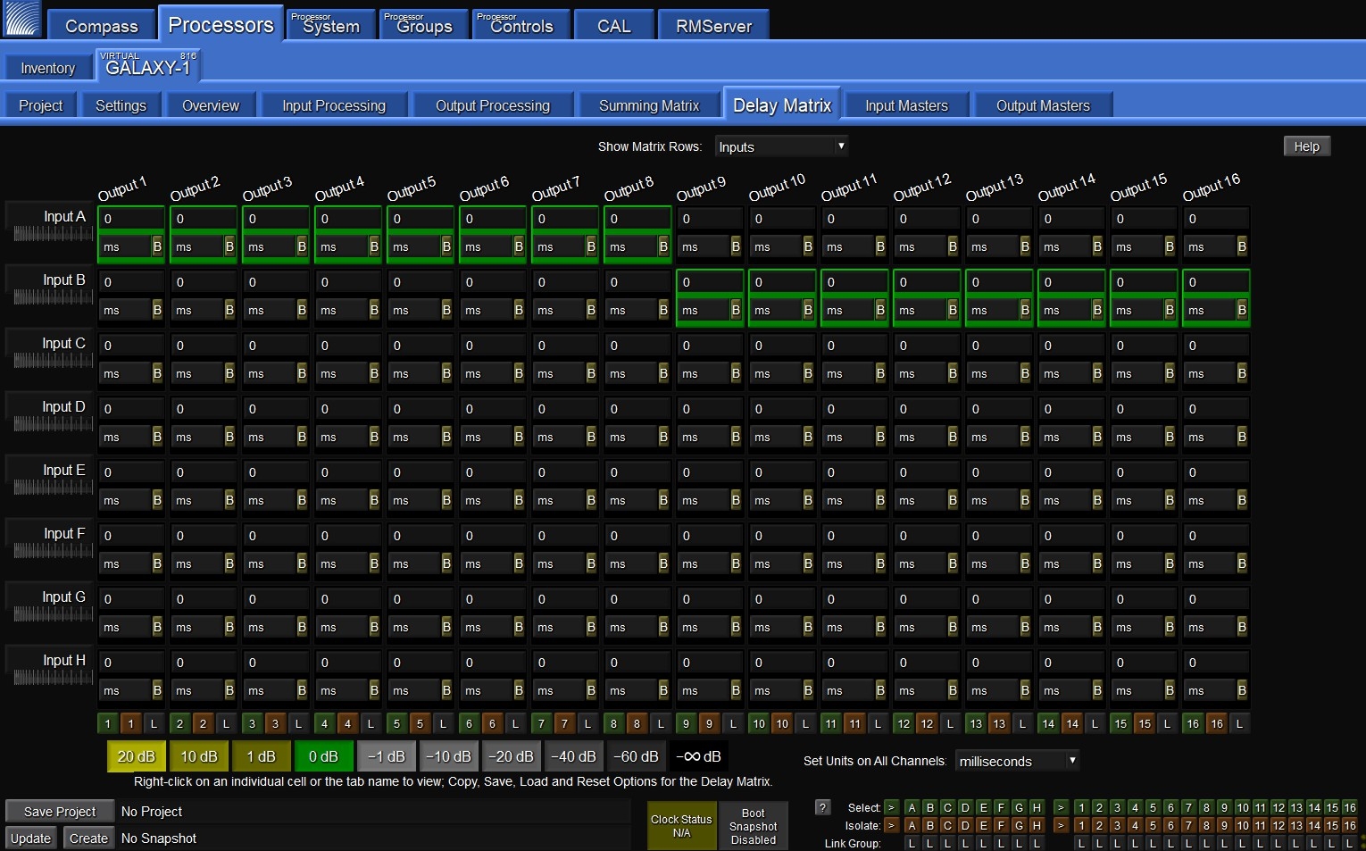
Processor > Delay Matrix tab
Input Masters tab
The Input Masters tab, shown in the figure below, provides fader controls to adjust the signal levels of the Inputs by decibels (dB).
Clicking above or below the handle results in single dB increments or decrements; clicking on a dB value to the right of the control will cause the gain to jump to that value.
There are also buttons to link channels of the same type by “Selecting” them, temporarily isolate a channel from other channels to which it is linked, or link groups to select multiple channels simultaneously.
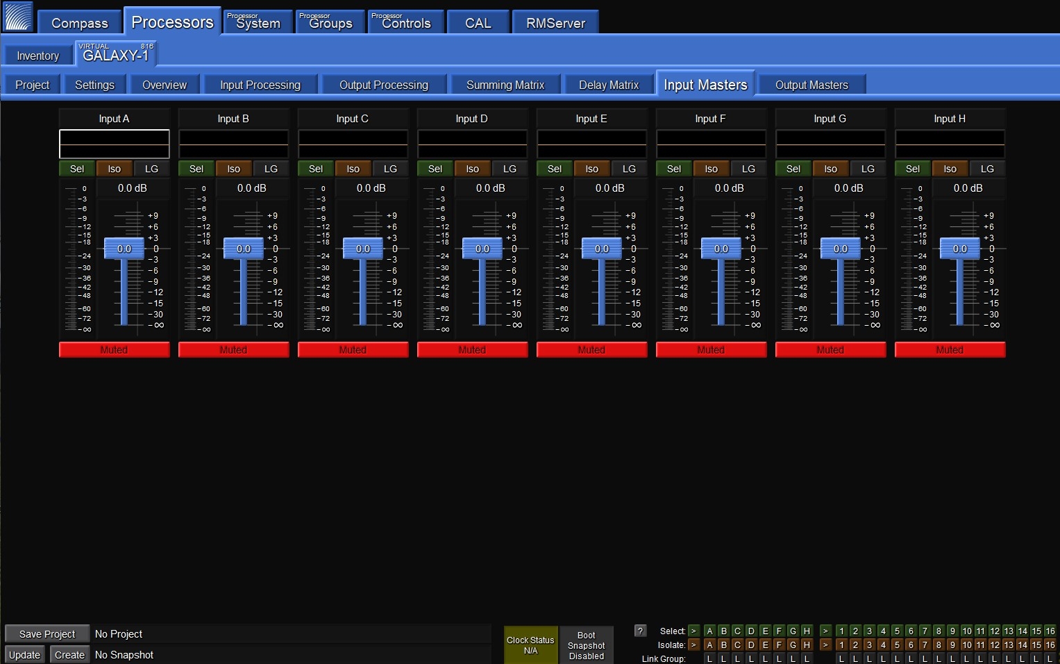
Processor > Input Masters tab
Output Masters tab
The Output Masters tab, shown in the figure below, provides fader controls for adjusting the signal levels of the Outputs by decibels (dB).
Clicking above or below the handle results in single dB increments or decrements; clicking on a dB value to the right of the control will cause the gain to jump to that value.
There are also buttons to link channels of the same type by “Selecting” them, temporarily isolate a channel from other channels to which it is linked, or link groups to select multiple channels simultaneously.
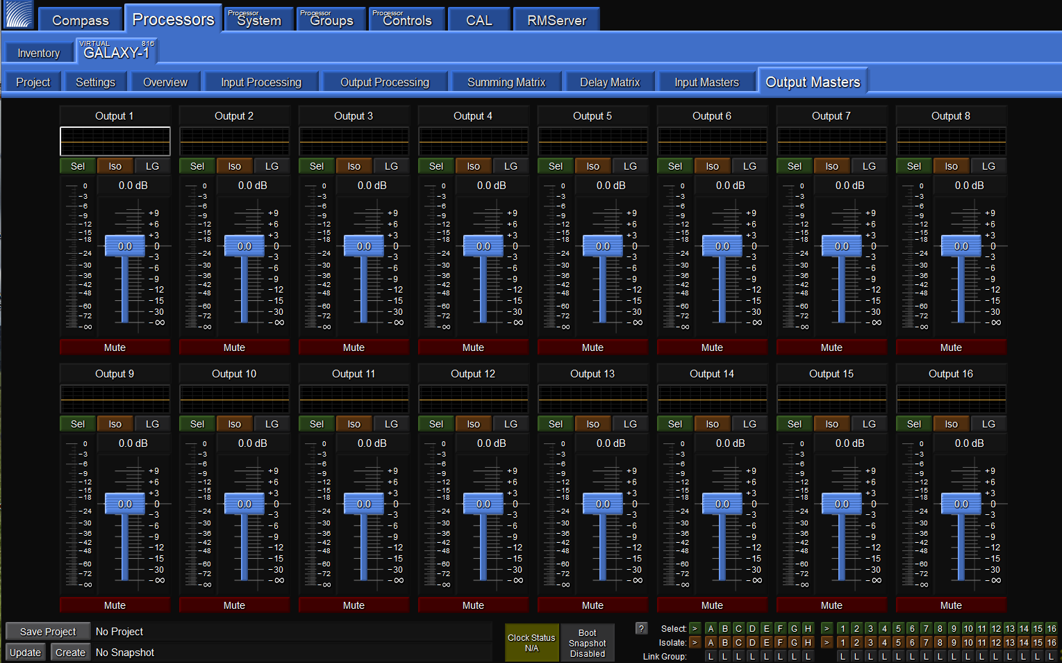
Processor > Output Masters tab
System tab
The System tab allows a user to view settings for multiple GALAXY processors simultaneously in one window. It is
read-only. Under the Inventory tab, select the processors to display by clicking on the small buttons to the far right of each device row, shown in the figure below. If blue, the settings for this device will display in the Processor System tab. If gray, they will be excluded. To enable viewing the same processor in two Compass application windows click the number 2 in the Window column, then click Show Secondary Processor Tabs Window.
Within the System tab display, there are controls for moving the displays to customize the view and pan/zoom capability.
Note
Any customized view created is not saved with the Compass Project.
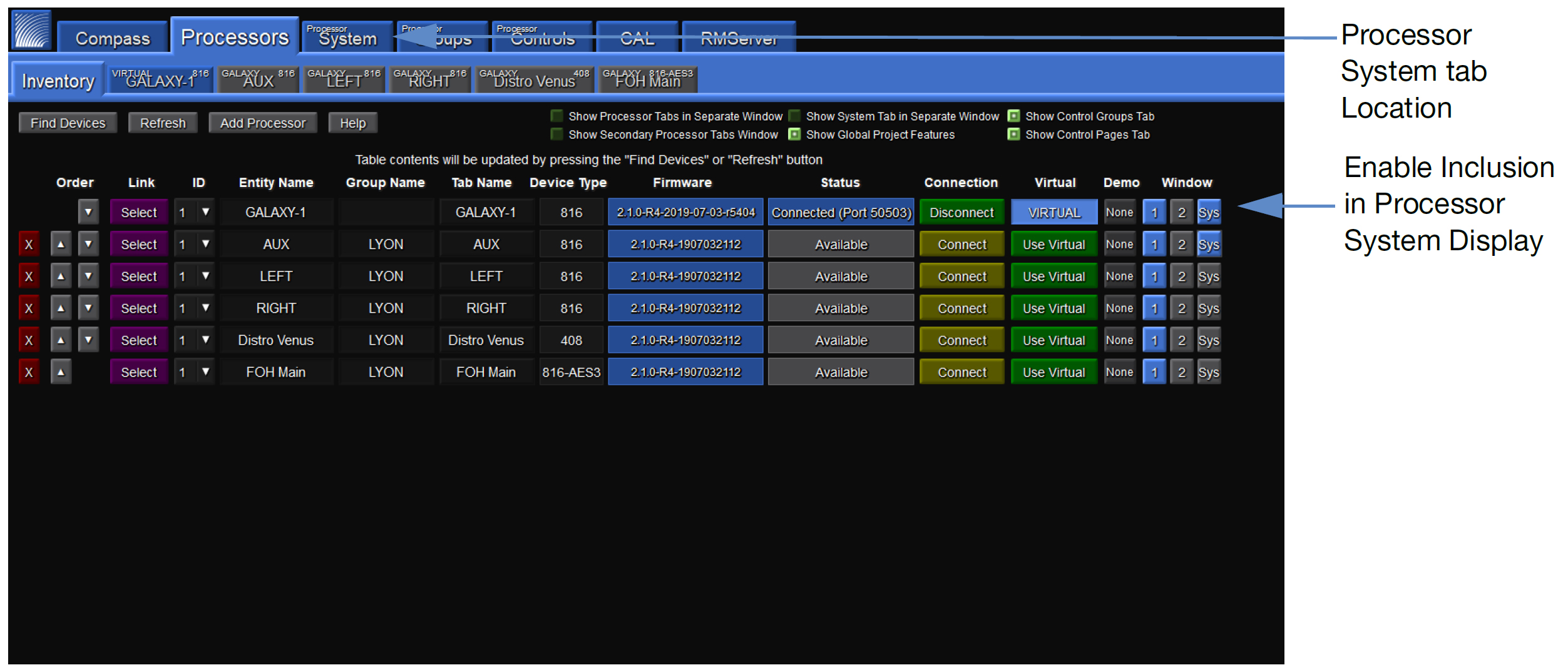
Enabling System View
Processor Groups tab
Users may choose individual channels from across multiple GALAXY devices to be a Group in the Processor Groups tab. Each Group will have a separate sub tab and as many groups as are desired may be made. Individual Groups or collections of multiple Groups can be saved and reloaded. The Group function allows users to gang inputs or outputs together from a single or multiple GALAXY processor(s) in a way that makes sense for a particular application. These Groups may then be controlled via the Processor Controls tab.
Processor Controls tab
Controls are added and assigned to Groups, moved and resized, and adjusted in the Processor Control tab. There are three modes: Layout, Configure, and Operate, which are selected in the upper-right corner. Choose Layout to add controls, gain, mute, etc., move and resize. Choose Configure to make Group selections for each Control. In Operate mode, the Control makes relative changes to all of the inputs or outputs assigned to the Group to which the Control is assigned. Controls that may be added are Delay, Gain, Mute, EQ Bypass, EQ Plot, Meter, and U-Shaping Gain. There is also an option to include a background image.
Audio signal flow
All GALAXY processors offer the same processing for audio signals. However, the inputs and outputs are different, so the signal flow is also slightly different. This section provides signal flow diagrams for all three processors and a few more details about terminology.
Common terminology
For clarity, a few definitions are repeated in the table below. The GALAXY processors can serve as both AVB listeners (receive networked audio data streams) and AVB talkers (generate networked audio data streams).
Name | Description |
|---|---|
Listener | A device that is capable of receiving one or several streams. |
Sink | A virtual input connector that can receive and unpack one stream. |
Source | A virtual output connector that can generate and transmit one stream. |
Talker | A device that is capable of transmitting one or several streams. |
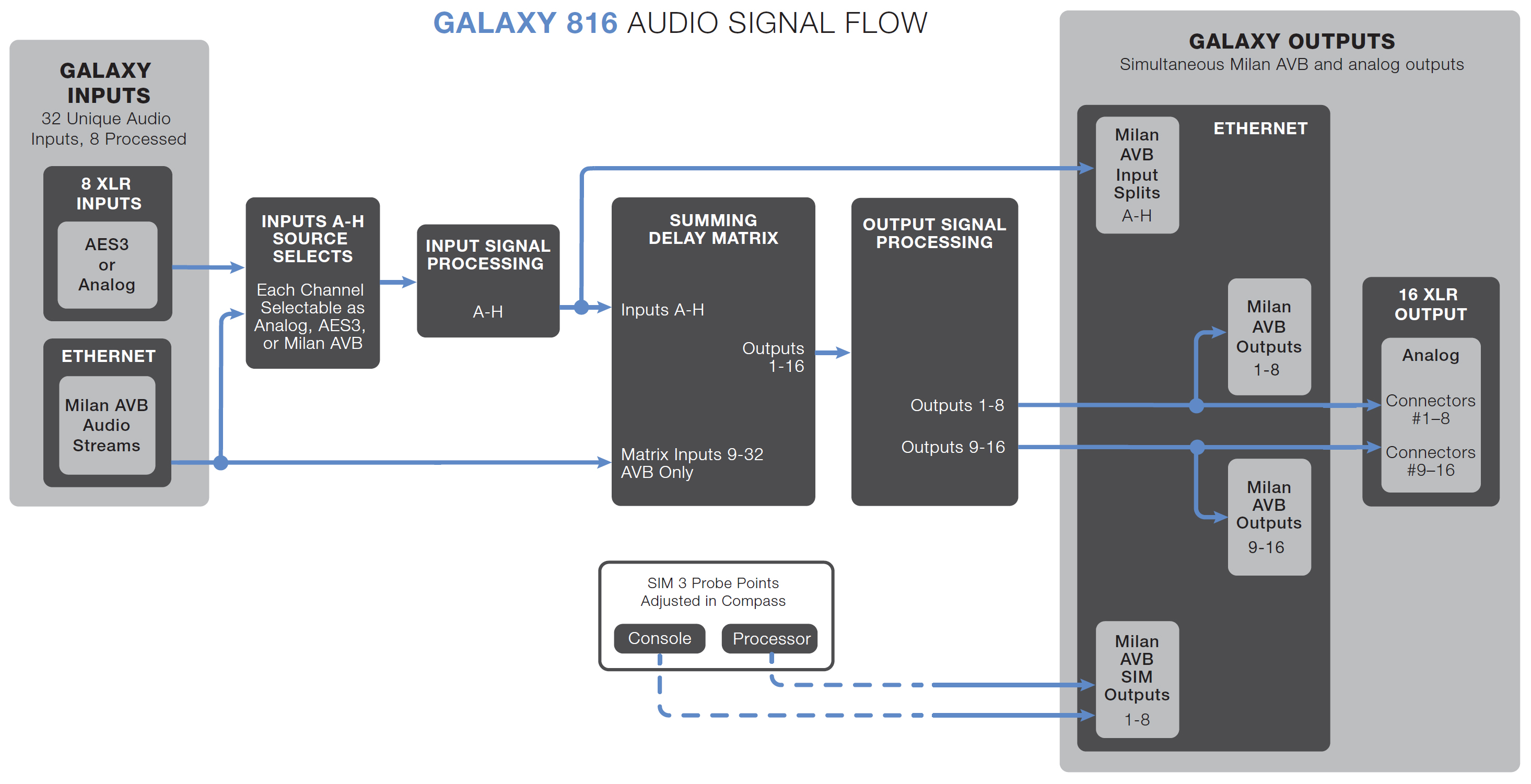
Through the Ethernet ports, GALAXY processors can function as listeners capable of accepting up to 8 streams of AAF/AVB audio input. Each stream can contain up to eight channels. An additional stream serves a GALAXY processor clock sink. The table below provides stream-to-channel translation.
Listeners (stream inputs) | Channels |
|---|---|
Stream input 0–7 | GALAXY processor up to 8 inputs as assigned |
Stream input 8 | GALAXY processor clock sink 1 |
The GALAXY processors can also function as talkers through the Ethernet port. GALAXY processors are capable of generating 6 output streams with varying output types further described in the table below. An additional stream serves as a GALAXY processor clock source
Talkers (stream outputs) | Channels |
|---|---|
Stream output 0 | GALAXY processor outputs 1–8 (96 kHz) |
Stream output 1 | GALAXY processor outputs 9–16 (96 kHz) |
Stream output 2 | GALAXY processor SIM outputs |
Stream output 3 | GALAXY processor Inputs A–H split (post input processing) |
Stream output 4 | GALAXY processor outputs 1–8 (48 kHz) |
Stream output 5 | GALAXY processor outputs 9–16 (48 kHz) |
Stream output 6 | GALAXY processor clock source 1 |
GALAXY 816 processor audio signal flow
The figure below illustrates the audio signal flow for a GALAXY 816 processor. For details about clocking, see Clocking.
Audio signal flow for the GALAXY 408 processor
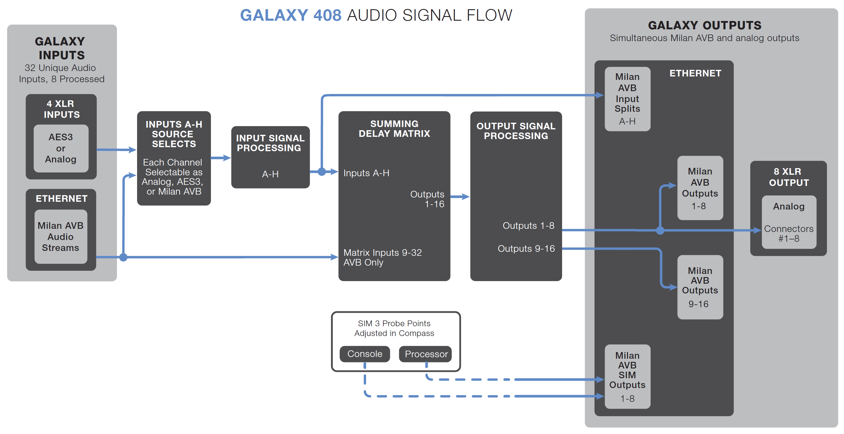
GALAXY 408 processor audio signal flow
The figure below illustrates the audio signal flow for a GALAXY 408 processor. For details about clocking, see Clocking.
Audio signal flow for the GALAXY 408 processor
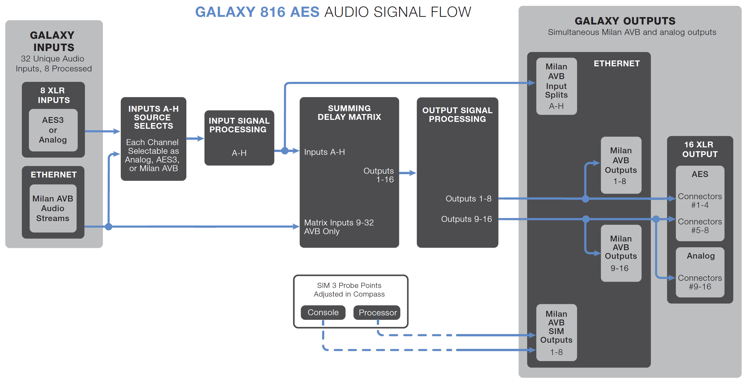
GALAXY 816-AES processor audio signal flow
The figure below illustrates the audio signal flow for a GALAXY 816-AES processor. For details about clocking, see Clocking.
Audio signal flow for the GALAXY 816-AES processor
Clocking
Media clock for a single GALAXY processor
Note
Media clock is the common terminology used in the Milan specification. Within the GALAXY processor settings: Input and Output tab, the media clock choice is selected under the System Clock: Clock Mode pull-down menu.
The GALAXY 816 processor and the GALAXY 408 processor offer four clock options for the media clock: GALAXY internal clock, CRF clock stream, AAF audio stream clock, and AES3 clock (the first four choices shown in the figure below, GALAXY System Clock Selection box).
The GALAXY 816-AES3 processor offers the same four plus a Word Clock of 48 or 96 kHz via an additional BNC connector.The GALAXY 816-AES3 processor can be synchronized to an external source depending on the digital input selection: AES3 offers discrete values in the range from 20–216 kHz (see Input sample rates).
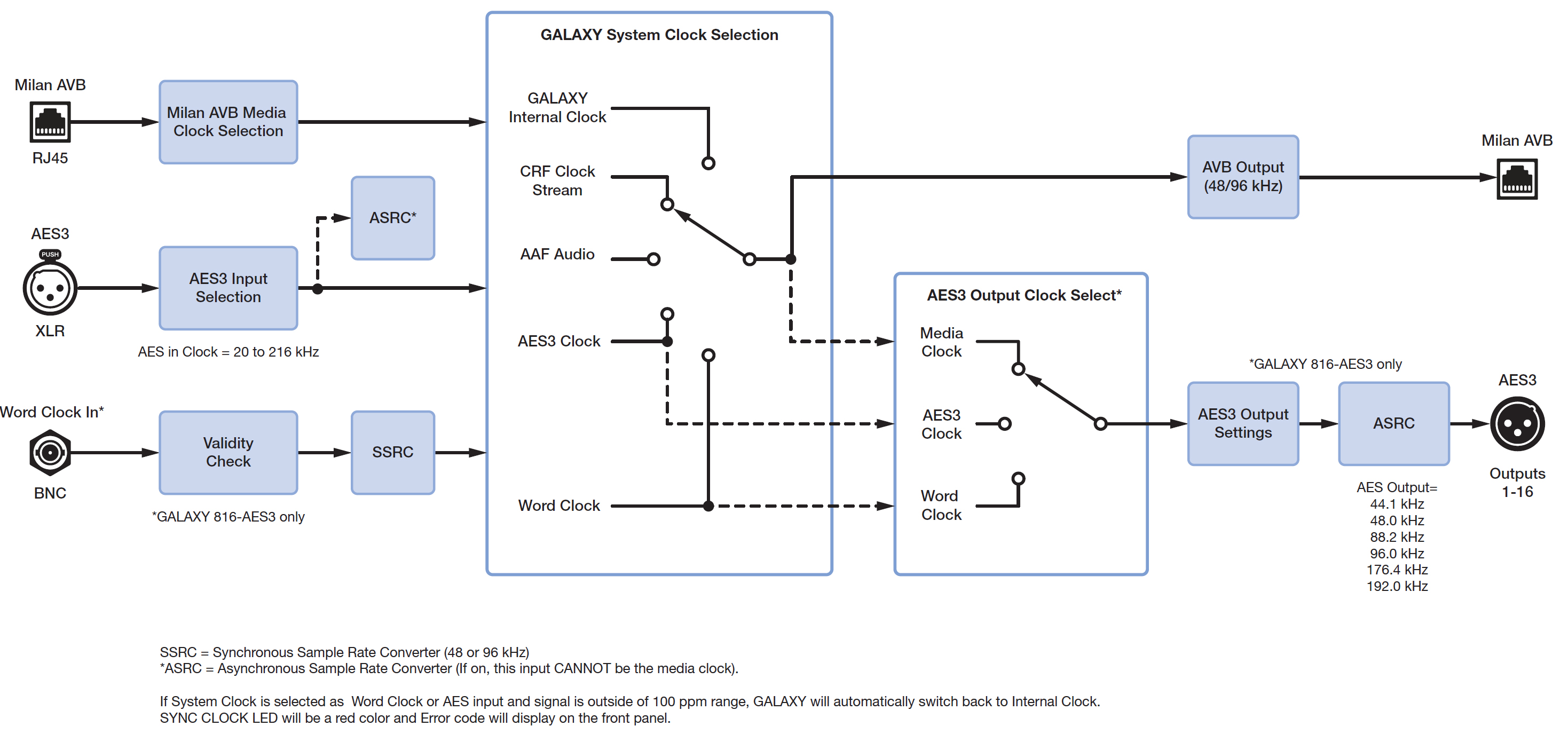
GALAXY processor clocking scheme
Note
For an AES3 input to be selectable in the System Clock, Clock Mode drop-down, it must be synchronous to the GALAXY internal clock (48 kHz or 96 kHz ±100 ppm). Synchronous means the external source and the GALAXY processor have a common clock (to within ±100 ppm). A common clock with the sender of data is necessary for any device to accurately interpret the binary data it receives. If the device clocks are asynchronous—any of the allowable AES input clock rates NOT equal to 48 kHz or 96 kHz, and thus not common with the GALAXY internal clock—they cannot be used as a system clock. Furthermore, any audio input associated with this asynchronous clock must pass through the Asynchronous Sample Rate Converter (ASRC) to make that input data synchronous, or accurately aligned to the GALAXY processor's internal processing clock.
Common media clock for multiple interconnected GALAXY processors
When connecting multiple GALAXY processors, one common media clock must be used. Clocks should never be daisy-chained. Even small timing differences can cause audible audio degradation. The three figures below illustrate common multiple GALAXY processor clocking configurations for networked GALAXY processors. They do not cover all possible clocking schemes.
For more information about networking schemes in general, see the AVB Networking Guide.
The first figure below illustrates an example where an analog or asynchronous AES3 input must be sent through several GALAXY processors. While an audio signal may be daisy-chained from one GALAXY processor to the next, it is worth repeating that the clock must never be daisy-chained. In the case illustrated in the first figure below, GALAXY 1 receives an analog or asynchronous AES3 input, and its system clock should be set to Internal to use the device clock. For an AES3 Asynchronous signal, the asynchronous AES3 Sample Rate Converters (ASRC) must be enabled for that input.
Subsequent processors (in this case GALAXY processors 2, 3, 4 and 5) must receive their system clock from the same source (GALAXY 1), which can be accomplished by using the CRF clock (Clock Reference Format packets) from GALAXY 1.
Note
An AAF clock may also be sent from GALAXY 1 as a media clock, but the CRF clock is preferable as it is more bandwidth efficient.
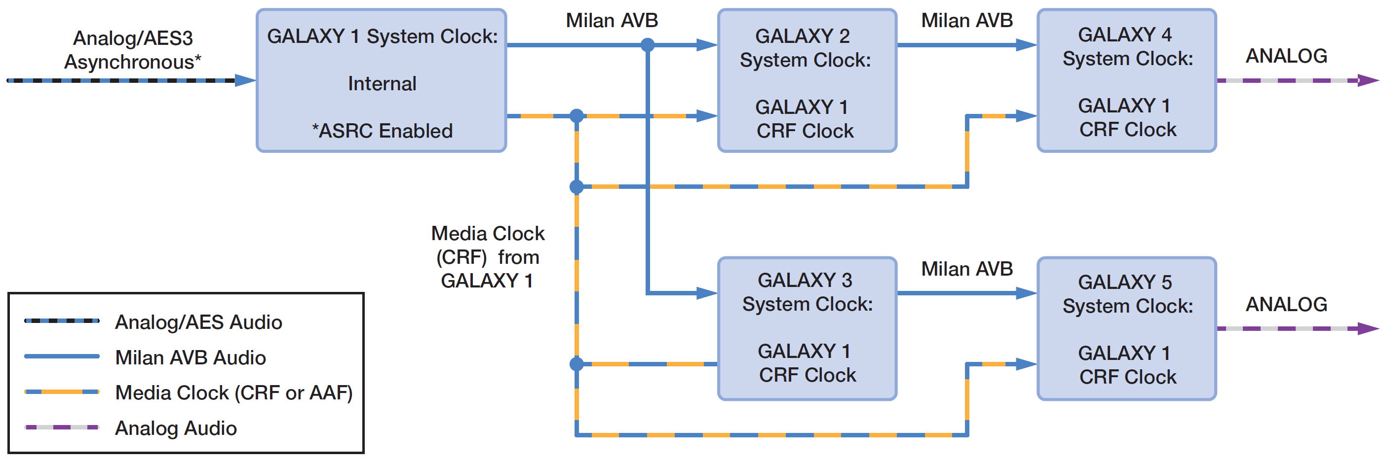
Clocking scheme for multiple GALAXY processors — analog or AES3 asynchronous inputs
The figure below illustrates an example where an AES3 signal aligned to a word clock must be sent through several GALAXY processors. Again, the clock cannot be daisy-chained along with the audio signal. In this case, if GALAXY A (which must be a GALAXY 816-AES3 processor) receives an AES3 input synchronized at its source to a word clock, its system clock should be set to the word clock received from the same source via the BNC connector. In this case, the AES ASRC must be disabled.
Subsequent processors (GALAXY processors B, C, D and E, which can be any GALAXY processor model) must receive their system clock from the same source (GALAXY A). Use the CRF clock (Clock Reference Format packets) from GALAXY A as the system clock mode selection. The AES ASRC for succeeding GALAXY processors (B, C, D, and E) must also be disabled.
Note
An AAF clock may also be sent from GALAXY A as a media clock, but the CRF clock is preferable as it is more bandwidth efficient.
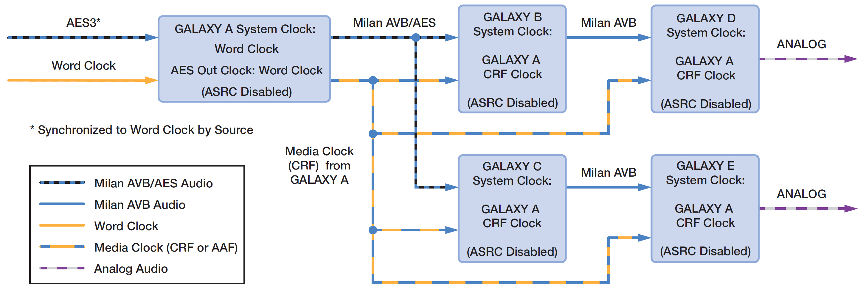
Clocking scheme for multiple GALAXY processors—AES3 input with word clock
The figure below illustrates an example where an AVB signal coming into the first GALAXY processor must be sent through several GALAXY processors. Again, the clock cannot be daisy-chained along with the audio signal. In this case, the source of the AVB signal must also provide the media clock, because GALAXY 1 would add latency, as it is essentially daisy-chained itself from the input source. In this case, all GALAXY processors (1–5) can receive the same media clock by dedicating 1 of the available 32 AVB channels to act as a system clock. Select the system clock mode to be any of the AAF audio streams.

Clocking scheme for multiple GALAXY processors—AVB input source
Digital latency
GALAXY processors feature fixed latency across all output channels, regardless of the processing applied. The analog latency for GALAXY processors (AD/DA) is fixed at 0.5968 milliseconds. GALAXY processor AES3 inputs have sample rate converters that support a range of sample rates. Changing the sample rate can increase the latency to approximately four times this value, depending on the sample rate selected.
Note
While each GALAXY processor has fixed latency, overall system latency from a local GALAXY processor’s (talker) physical analog outputs and any remote GALAXY processors’ (listeners) physical analog outputs can vary. To ensure proper alignment, measure the delay between the local GALAXY processor’s physical analog outputs to any remote GALAXY processor(s) physical analog outputs using an accurate audio analyzer (such as Meyer Sound’s SIM System).
Input sample rates
With the ASRC enabled, the GALAXY processor can accept a range of sample rates for AES inputs, as shown in the table below. To use AVB inputs, a common clock must be selected.
Table 4: Accepted Input sample rates and bit depth based on format
Format | Input sample rates accepted (kHz) | Bit depth |
|---|---|---|
AES3 | 20 – 216 | up to 24 bit |
AVB | 48 or 96 | 24 bits in 32 bit integer |
AES3 output sample rates
If an AES3 or word clock input is selected as the AES output clock source (GALAXY 816-AES3 processor only), then the following sample rates may be used:
44.1 kHz
48.0 kHz
88.2 kHz
96.0 kHz
176.4 kHz
192.0 kHz
Product integration
Product integration combines both delay integration and starting point settings in a single dialog. Using product integration is the first step to complete when optimizing a system. It is not recommended for use when a system has previously been optimized, as some or all of the output processing filters and settings may be over-written.
By selecting the loudspeaker model in the pop-up window, the Delay and Starting Point drop-down menus are populated with the available options.
A video describing product integration in more detail is available at meyersound.com/videos/#support
Delay integration
Delay integration aligns the phase responses of different loudspeaker model families to match predefined target curves.
After selecting the product this setting will apply to, choose the desired target phase curve frequency: 55-70, 100, or 125 (Hz). Different products will have different phase curve options available, though PC125 will be available for every product. Choose the lowest target phase curve that is available for all loudspeaker types in a system.
Some subwoofer delay integration settings also implement filters that change the frequency response of the product. This is necessary to achieve the appropriate phase response to be compatible with the phase curve family.
Starting points
There are two kinds of starting points:
Filter presets for line array models
Delay and polarity settings for the rear-facing element(s) of gradient subwoofer arrays
Line array models
When certain line array products are chosen, the user can select a starting point from the drop-down menu. These presets use U-Shaping filters that adjust the frequency response to a usable result. For most products, the response will be close to equal magnitude (flat) for arrays that are 6-8 elements.
Some line array products have presets that are based on the total splay angle between four elements, shown as Wide, Medium, or Narrow. Choose the setting that best matches the splay angles between the elements this output channel will be driving.
For example, if an output will be driving four elements of a LYON-M array where there is 3° of splay between every element, the total splay between four elements is 9°, and the “Medium” preset would be most appropriate.
Some line array products have a single preset that can be used as a starting point in any configuration. If a line array product does not have a starting point preset available, it is designed to be used in native mode and does not require a preset.
Subwoofers
Starting point settings for some subwoofers provide a choice to select a front or rear-facing subwoofer. These settings are designed for subwoofers being used in gradient configurations that produce cardioid coverage patterns. Selecting a front facing starting point will not implement any processing for most models. Selecting a rear-facing starting point will invert the polarity and implement appropriate delay to synchronize the output of the rear-facing element with the output behind the array of the front-facing elements. This delay is applicable to subwoofers that are physically reversed in an array or ground stack.
Product integration by loudspeaker
To implement Product Integration:
Select the Overview tab.
Click the Product Integration button for any output to open the dialog.
Select the loudspeaker model connected to the output from the Product drop-down menu.
Select the lowest DI standard that is common to all models used in the system.
Select the starting point processing to use for this output. The available target phase curve selections are:
pc55-70
pc100
pc125
Systems comprising multiple loudspeaker types with different native phase responses can result in undesired summation or cancellation in the low-mid frequencies. As Meyer Sound improves the native phase response of its loudspeakers, the product integration feature quickly matches the phase responses of mixed loudspeaker models used in a given system.
Product integration is available on every GALAXY processor output.
The native phase curves exhibited by Meyer Sound products can be differentiated by the lowest frequency at which each product deviates by 180 degrees of relative phase. Product integration uses the concept of phase curve families shared by different products: For example, LYON (see the figure below, red line) and LEOPARD loudspeakers both have a low-mid phase response of 180 degrees at 55 Hz (pc55-70); LEO-M (see the figure below, blue line) and UPQ loudspeaker both have a low-mid phase response of 180 degrees at 100 Hz (pc100).

LYON (red) and LEO-M (blue) phase response plots
Product integration example
Product Integration is especially appropriate when applied to loudspeakers that are not in the same native phase curve family. For example, to accomplish product integration for LEOPARD with UPQ-1P:
Enable product integration on both the LEOPARD and UPQ-1P outputs.
Select pc100 for both outputs.
Use pure delay to time align the two loudspeakers at a coverage location where they are equal in level.
Select the Overview tab to verify all loudspeaker system outputs are set to the same phase curve value.
Technical notes
For best results, apply the lowest common phase curve value to different loudspeaker models. For example on the UltraSeries models, pc100 is the lowest common value.
Although the M Series phase response is 180 degrees at 350 Hz, it can be improved by using pc125 when used in close proximity to other Meyer Sound loudspeakers.
When Product Integration is applied to subwoofer outputs, the phase slope is optimized to align with the mid-high loudspeakers using the same phase curve setting.
The changes in phase response caused by product integration are not displayed in Compass, but they can be modeled in MAPP or measured using the transfer function in SIM.
If a delay integration standard is selected that natively exhibits the same phase curve frequency, the output processing will not be altered. For example: LEO-M is natively pc100. If product integration is enabled for LEO-M and set to pc100, no measurable change occurs.
Low-Mid Beam Control (LMBC)
Low-Mid Beam Control (LMBC) is a tool that utilizes signal processing to help line arrays achieve more consistent frequency response over their vertical coverage. LMBC allows the low-mid frequency coverage of an array to be shaped (increase the vertical width) or steered (modify the direction) so that it more closely matches the array's high-frequency coverage.
Based on user-entered parameters, LMBC generates specific, unique All Pass filters for elements in a line array. These All Pass filters adjust the relative timing of low-mid frequencies compared to high frequencies, essentially allowing low-mid frequencies to be modified without affecting the coverage of high frequencies that are controlled by the horn. The result is more consistent coverage across the entire operating range of the array.
For an in-depth explanation of the theory behind LMBC, see the video on the Meyer Sound website: meyersound.com/videos/#support
LMBC should always be modeled in MAPP so that performance can be evaluated before it is implemented. To use LMBC, under the Processors tab:
Select the GALAXY processor that is controlling the line array to be modified.
Select the Settings > Low-Mid Beam Control tab, shown in the figure below.
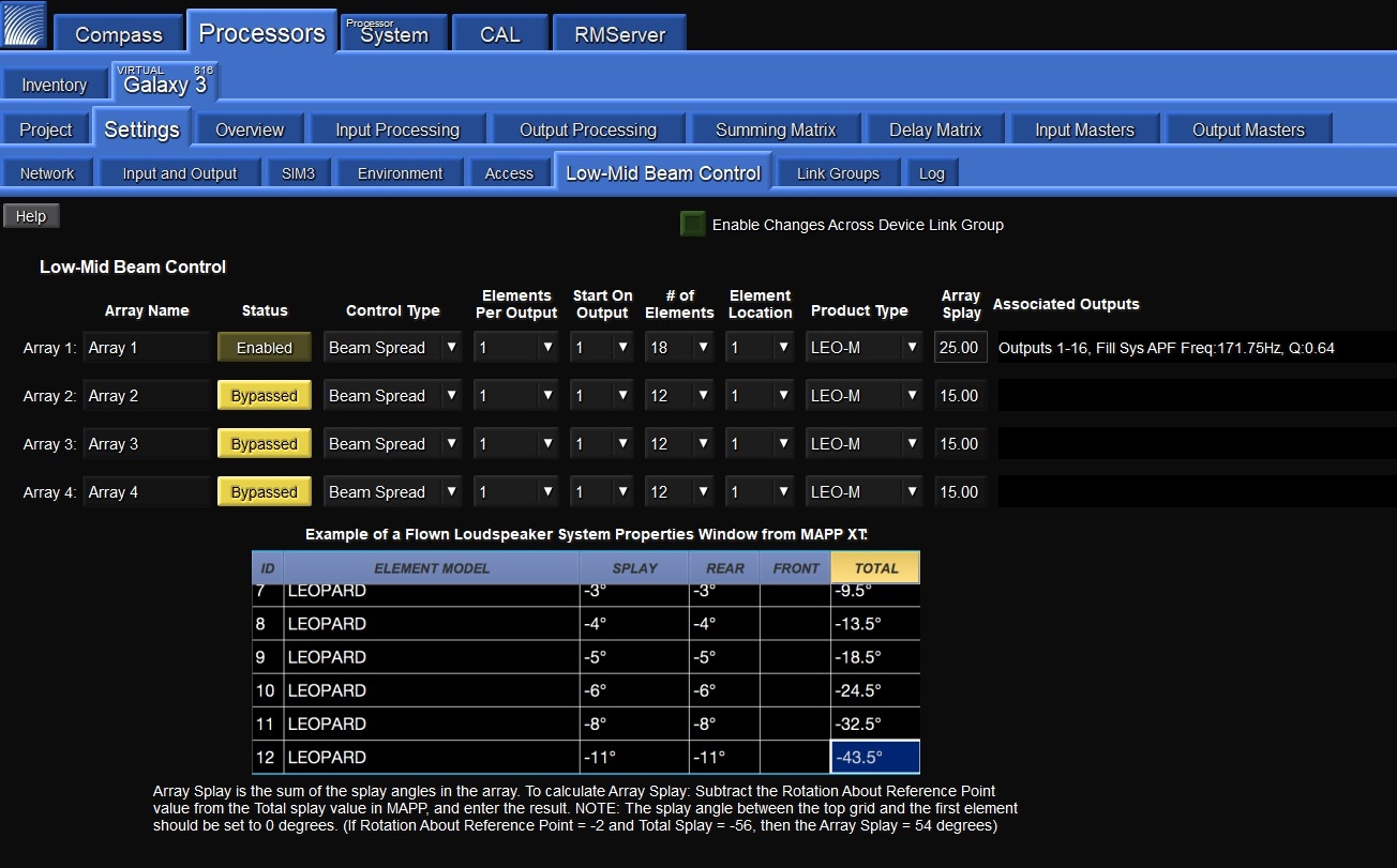
Low-Mid Beam Control tab
Under the Low-Mid Beam Control tab, there are a number of settings the user can control:
Low-Mid Beam Control
Low-Mid Beam Control is a tool for GALAXY processor users to modify the natural vertical coverage of the low to mid frequencies of a Meyer Sound line array (up to 32 elements) to more closely match the high-frequency coverage (see Low-Mid Beam Control (LMBC)).
Array Name widget
Each line array being driven by this processor can be named for quick identification by clicking in the Array Name widget and entering the appropriate text.
Status button
The Status button enables or bypasses LMBC processing for all affected channels.
Control Type
Under Control Type, the user can select one of two coverage patterns: Beam Spread, or Steer Up. Beam Spread will widen the low-mid frequency coverage. Steer Up will steer low-mid frequency upward. The appropriate Control Type should be determined in MAPP prediction software.
Elements Per Output
The Elements Per Output control lets the user select whether a single processor output will drive one or two line array elements. Use one element per output for best performance.
Start On Output
Start On Output specifies which output channel will be used as the first output channel of LMBC. Element number one (1) always starts at the top of the array.
Number of Elements widget
The Number of Elements widget defines the number of elements within the array.
Element Location widget
The Element Location widget determines the element's relative position in the array. Use of this tool is necessary when LMBC processing is spread across multiple processors. For example, consider a 24-element array where each element receives a discrete LMBC filter. Two GALAXY processors are required (GALAXY A and GALAXY B). If elements 1-16 are driven by output channels 1-16 on GALAXY A, the element location for GALAXY B would be 17. Both processors 'start on output' value would be set to output 1.
Product Type widget
The Product Type widget specifies the line array product.
Array Splay widget
The Array Splay widget allows the user to enter the summed total of the splay angles within the array. To calculate array splay using the MAPP System Design Tool:
Determine the correct value from MAPP’s Array Splay located in the Loudspeaker System Properties dialog box.
Enter the result from the Compass or Compass Go Array Splay column.
Note
The splay angle between the top grid and the first element should be set to 0 degrees.
Associated Outputs
Associated Outputs display the processor outputs associated with an array’s LMBC processing. It also provides All Pass filter parameters (center frequency and Q) that can be applied to fill loudspeakers connected to other processor outputs to optimize alignment with the line array system using LMBC. In the example figure below, LMBC has been enabled for an array of LEO-M loudspeakers (Array 1).

LMBC enabled for beam spread of a LEO-M line array
Once LMBC has been enabled, the All Pass filters can be seen on each Output Processing Channel, and via the (output) Processing thumbnails on the left side of the Overview tab.
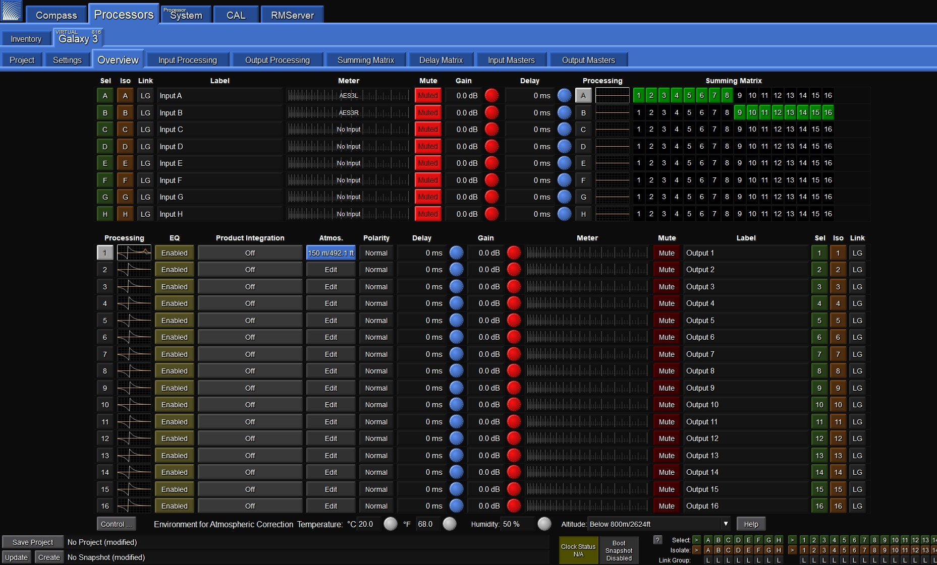
The Processing column on the Overview tab Indicates the LMBC All Pass filters
Tips for using LMBC
Signal drive lines must have correct polarity.
Apply LMBC before any other EQ is applied.
Gain tapering can make LMBC ineffective.
Do not treat array zones with different processing/gain below 1000 Hz. (e.g., correct for low-mid buildup with the same filters on the entire array, correct for HF distance only above 1 k on individual zones).
Spread is not optimal above 95° total array splay.
Steer up is not optimal above 45° total array splay.
One array element per output is optimal.
Two array elements per output is maximum and can only be used with arrays of twelve elements or more. Grating lobes will occur using this setting.
Compass control software disallows invalid or non-optimal configurations.
LMBC is not designed for mixed product types in one array.
All speakers within a system should be set to the same delay integration phase curve (PC) setting.
Atmospheric correction
Atmospheric correction overview
The GALAXY processor’s atmospheric correction uses atmospheric loss equations and pre-calculated values to maintain system response as temperature and humidity vary. The correction coefficients are determined by user-entered parameters: the environmental conditions, and unique to each output, atmospheric gain factor and distance.
Air absorption of sound is a complex, non-intuitive function, of which temperature, humidity, and distance have the most effect, changing how well higher frequency sounds propagate through air. The graphs in the figure below indicate a multitude of attenuation scenarios for just a handful of distances.

Atmospheric attenuation of sound scenarios
The figure below provides frequency attenuation curve examples for three different temperatures with a fixed distance of 100 meters, at seven values for relative humidity. Depending on the atmospheric conditions and the distance the array is throwing, the number of possible correction combinations can be quite large, but they are achievable with the GALAXY processor.
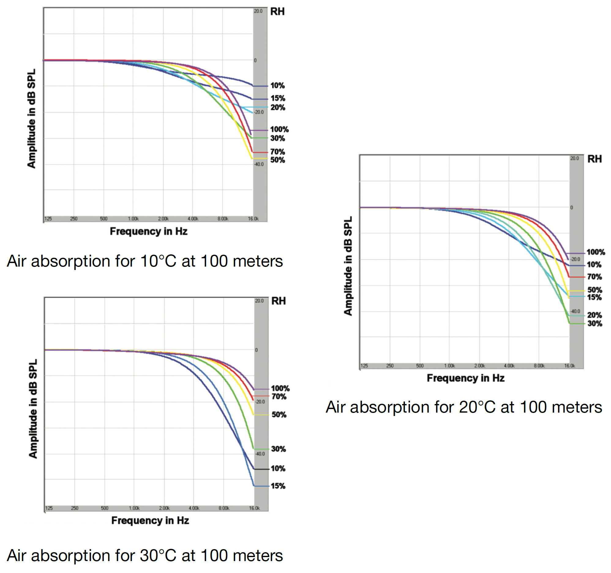
Frequency attenuation curves: 3 temperatures, all at 100 meters, and with seven relative humidity values
The GALAXY processor’s atmospheric correction filter function is limited to a maximum of 14 dB of boost when the atmospheric gain factor is set to 100%. Atmospheric correction does not try to correct to the highest frequencies. It is constrained to the range of frequencies that can be practically corrected, preserving headroom, unlike using a shelving filter.
The figure below provides frequency response curves for four different natural environments. The red curve indicates the frequency absorption due to the location’s atmospheric conditions if left uncorrected. (Note the roll-off at higher frequencies.) The green curve illustrates the frequency response of the atmospheric correction filters for that situation. The blue curve indicates the improved frequency response at higher frequencies for the resulting signal after applying atmospheric correction.
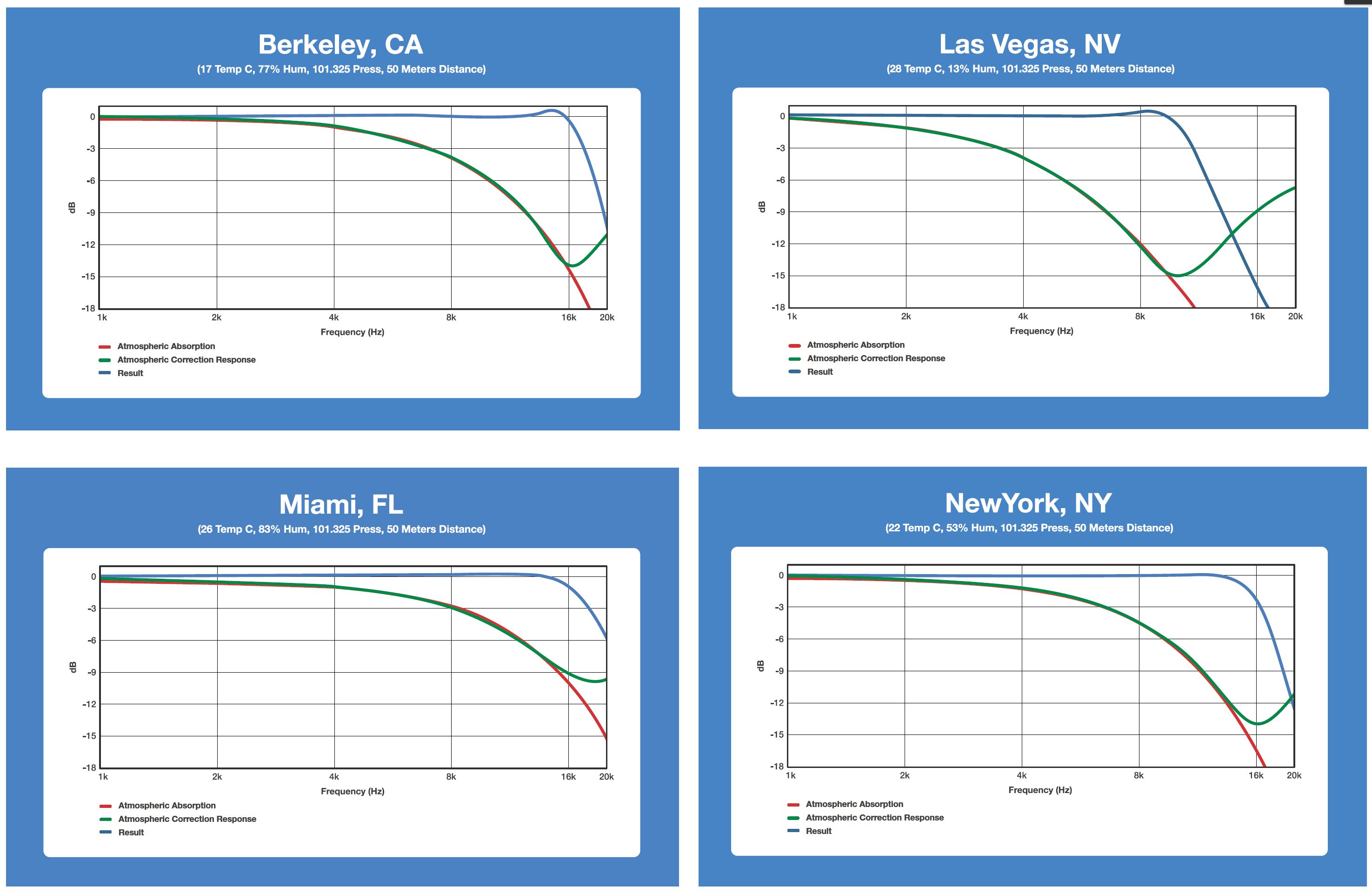
Atmospheric correction results for four different scenarios.
Using the GALAXY processor’s environmental conditions settings
To use the atmospheric correction function, the user must first set the environmental conditions. To do so:
Select a GALAXY processor in Compass.
Select the Settings > Environment tab.
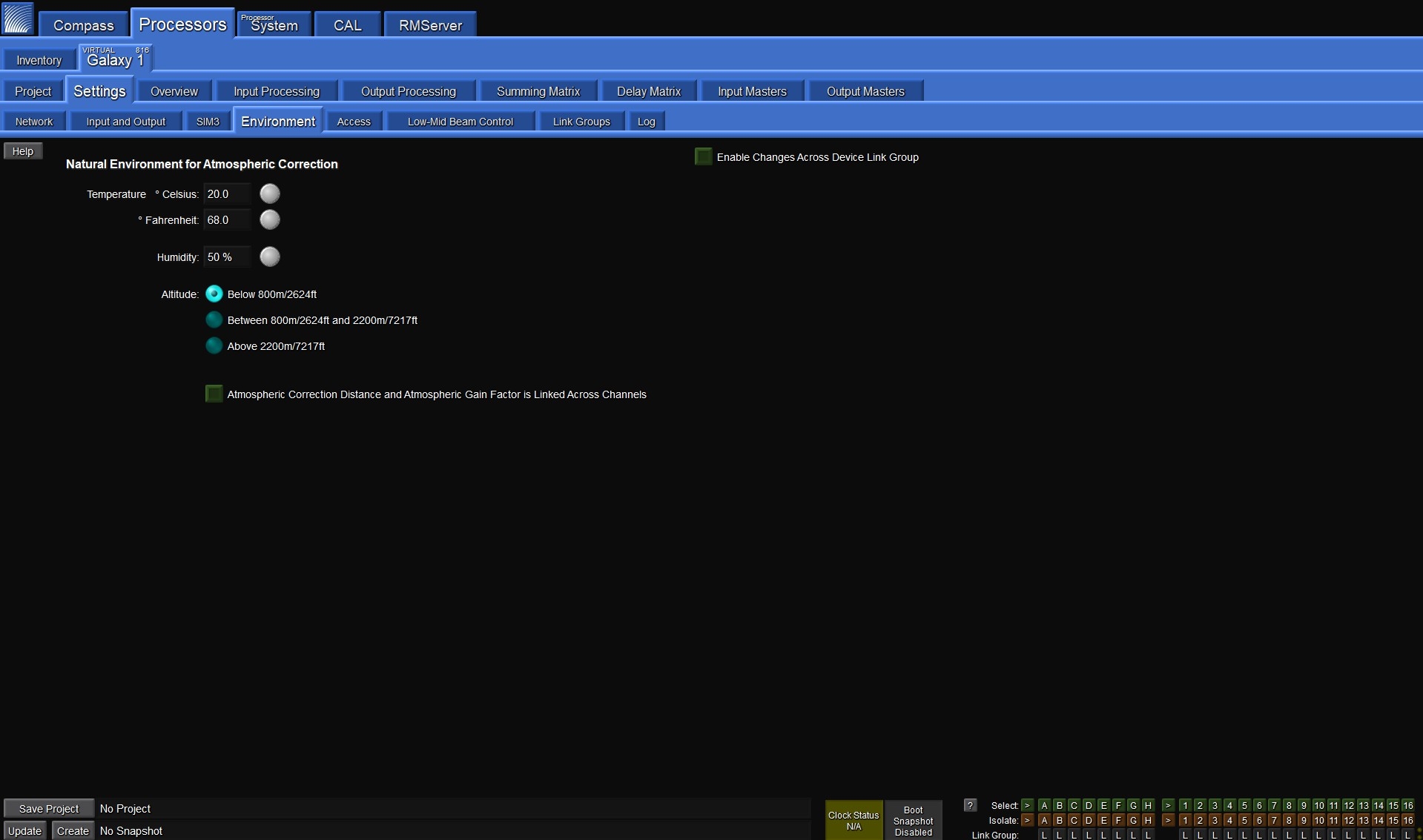
Environment Tab Settings
From this tab you can enter the current temperature and humidity, and select the appropriate altitude range. These values are used to implement the correction filters when atmospheric aorrection is enabled. All three parameters will affect the frequency, bandwidth and gain of the correction filters. These parameters should be adjusted continuously to match the current real-world conditions.
Tip
The ability to control these parameters is also possible from the bottom of the Overview tab.
For example, if a system is calibrated in the morning with atmospheric correction enabled, the environmental parameters should be updated to reflect the actual temperature and humidity throughout the day, maintaining the system response without over-correcting or unnecessarily reducing available headroom of the system.
Tip
A good rule of thumb is to update temperature or humidity settings in the processor if they differ from actual conditions by more than 5° Fahrenheit or 5% humidity.
To set atmospheric correction:
Select an output processing channel under the Output Processing tab. By default, the correction filters will not be shown in the plotter.
To make the filters visible, select the Response mini tab to the right of the plot, and check the box labeled Atmos. Corr. Response.
At the bottom of the window click once on the Bypass/Enable toggle button on the bottom right, next to the Atmos. Gain Factor and Distance settings to enable Atmospheric Correction.
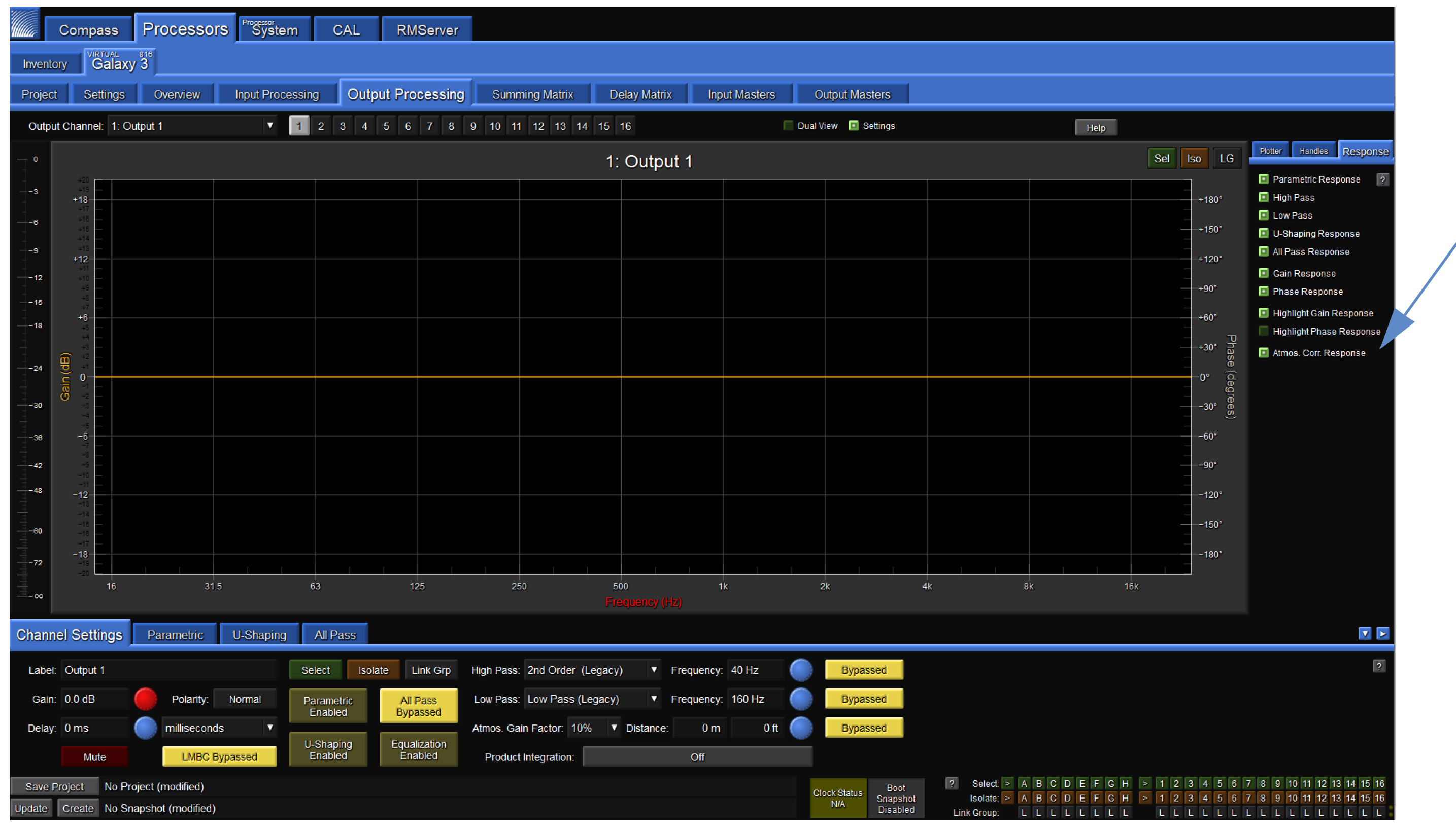
Atmospheric correction response enabled via Response mini tab within the Output Processing tab
Note
Atmospheric gain factor limits the amount of makeup gain added. When set to 100%, the filters are constrained to 14 dB of gain. When set to 50%, correction is limited to 7 dB of gain. Increasing the atmospheric gain factor will reduce headroom.
The Distance parameter should be set to the on-axis distance between the loudspeaker and the nearest listener. For example, it is common for the top element in a line array to be aimed toward listeners further away than the bottom element in the array; different values should be entered accordingly depending on what element in the array is being driven by each output channel. The maximum distance that can be entered is 150 meters (492.1 feet).
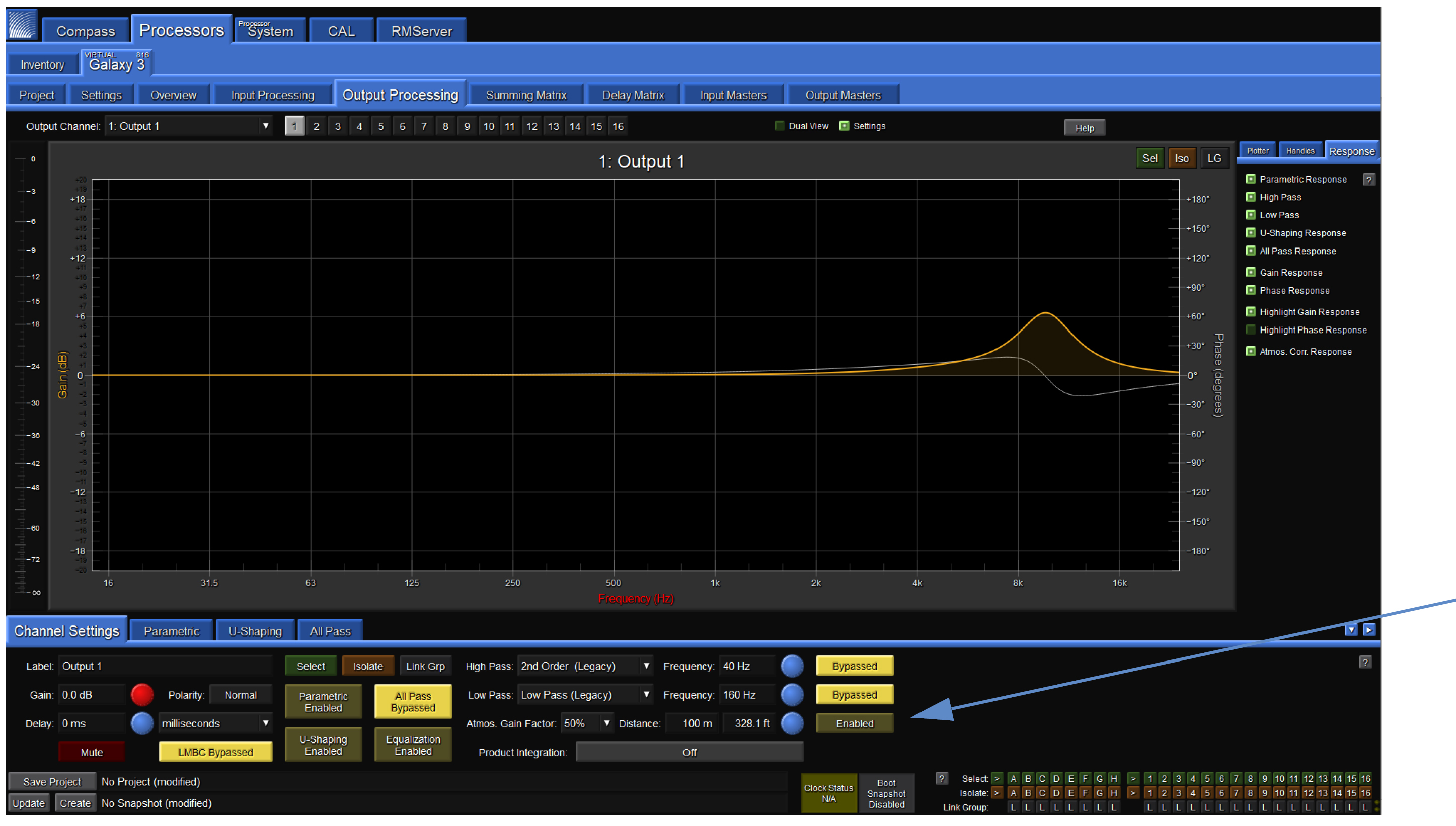
Atmospheric correction enabled and displayed
Keyboard shortcuts
Interaction with linking modes
Global and local linking preferences affect which channels are modified by keyboard shortcuts:
Global Device Select-Linking Mode—If the Global Device Select-Linking Mode is set to “All channels on the active GALAXY tab are always linked...,” then changes will also affect the same channels on any linked devices.
Gain Control Linking Mode and Delay Control Linking Mode—Gain and Delay changes across linked channels will be affected differently depending on Absolute or Relative mode (selectable in Compass: GALAXY Preferences > Isolate and Linking tab).
Mouse or typing
Press the indicated key to modify how a control is edited.
If using a mouse, press the indicated key(s) while clicking and dragging the mouse.
If using a keyboard only, press the indicated key while pressing the Enter key after a numeric value has been entered.
Isolate Current Channel
Control (Command on Mac) = Current Channel. Using this sequence isolates changes to the current channel, even if it is linked to other channels through Selects or Link Groups.
Link stereo pairs
Changes made to one channel will affect the stereo pair. Input pairs: A–B, C–D, and E–F. Output pairs: 1–2, 3–4, 5–6, etc.
Shift = Stereo Pairs. In the case of toggle buttons (Mute, Polarity, Bypass, etc.), pressing a button for one channel will set its stereo pair to an identical state.
Example 1: Channels A and B are both muted. Toggling Channel A while holding Shift will unmute both channels A and B.
Example 2: Channel A is muted and B is unmuted. Toggling Channel A while holding Shift will unmute Channel A but do nothing to Channel B.
In both cases, the result is Channels A and B are in an identical state: unmuted.
Alt-Shift = Stereo Pairs + Special Toggles. This command sequence behaves in the same way as Shift for all settings that are not controlled by toggle buttons.
In the case of toggle buttons (Mute, Polarity, Bypass, etc.), toggling a button for one channel will toggle its stereo pair as well, regardless of whether their states match up.
Example 1: Channels A and B are both muted. Toggling Channel A while holding Alt-Shift will unmute both Channels A and B.
Example 2: Channel A is muted and Channel B is unmuted. Toggling Channel A while holding Alt-Shift will unmute Channel A and will mute Channel B.
In both examples, the end result is that Channels A and B independently toggle from one state to the other.
Link all channels
Changes made to one input channel will affect all input channels; the same controls apply for output channels.
Control-Shift (Command-Shift on Mac) = All Channels. Changes made to all channels in a device.
Control-Alt-Shift (Command-Alt-Shift on Mac) = All Channels + Special Toggles. This sequence behaves in the same manner as Control-Shift for all settings that are not controlled by toggle buttons. (See similar examples in Link stereo pairs .)
Glossary
The following defines some of the terms used in the Compass Control Software GALAXY processor User Interface.
AAF | AVTP (Audio Video Transport Protocol) Audio Format |
AVB listener | A device that is capable of receiving AVB streams from an AVB talker. All available streams from all available AVB talkers that have the same group name on the network will selectable by the AVB Listener as inputs. |
AVB stream | An AVB stream functions much like an analog multi-cable. Each stream can vary in the number of channels and formats, similar to AES3 and standard analog multi-cables. The difference is that many audio streams can flow down a single Ethernet cable. Unlike traditional multi-cables, AVB streams do not stay connected when the audio devices are turned off. An AVB software controller creates and maintains these connections running on a computer attached to the network or inside one of the audio devices being controlled. An AVB controller in the audio device will maintain persistent connections and remake connections after power cycle or other interruptions, such as the unplugging of an Ethernet link. |
AVB talker | A device that is an AVB source capable of transmitting AVB streams. This device will send AVB streams to an AVB listener. When an AVB talker is on the network, it advertises its presence and the streams it is able to transmit. |
Channel | The channel name is used to identify a specific channel within an AVB stream. |
CRF | Clock Reference Format |
Cross-point | A point in the summing/delay matrix where the routing between inputs and outputs is assigned. |
Device settings | Current state of all control points (gain, EQ, delay, routing, etc.) of a GLAXY processor. |
Entity name | The entity name is used to uniquely identify an AVB entity. All entities must be unique within a group. |
Global environment | Environmental settings (temperature, humidity and altitude) for all linked devices. |
Global project | File saved to a computer that includes all of the Projects from the selected processors and the current device settings for each processor. |
Global snapshot | A snapshot, capturing all of the current device settings, which is stored in each processor, with the same name. |
Group name | Associates multiple AVB devices connected to the same network. The group name must be identical for an AVB talker (source) and AVB listener (sink) to establish AVB connections. |
Media status | Media status indicates whether the listener AVB stream is locked to the media clock rate of the AVB talker. |
MSRP | Multi-Stream Reservation Protocol |
MSRP accumulated latency | The worst case amount of time it will take a signal to pass from the AVB talker to the AVB listener. This value is calculated when the stream reservation value is propagated from the AVB talker to the AVB listener. |
Presentation time | A timestamp an AVB talker sends, set in the future with respect to the master clock time, for when the signal is to be ‘presented’ at the output of the AVB listener. This approach ensures that signals are reproduced simultaneously at different AVB listeners regardless of the varying path lengths a signal may have to traverse. |
Project | A file saved to a computer that includes all of the Snapshots stored in the GALAXY processor and the current device settings. |
Selected device | Devices that are designated to be globally linked by clicking SELECT in the Link column of the Compass > Inventory tab. The ID selection from the adjacent column allows for multiple global link groups of processors. There are three modes for global linking, selectable on the GALAXY Preferences > Global Linking tab. |
SIM | Source Independent Measurement |
Sink | An AVB listener has a least one sink, a virtual input. Each sink can receive one AVB stream. |
Snapshot | A snapshot contains all of the control point values captured, named, and stored in the GALAXY processor hardware. When snapshots are recalled, all of the control point values of GALAXY processor are overwritten with the stored values, with the possibility to exclude some parameters via the confirmation dialog. Snapshots are listed in the Snapshot Library on the Project tab and are limited to a maximum of 255. Click on the snapshot name to select, then click the desired function button on the right of library list. |
Source | An AVB talker has at least one source, a virtual output. Each source makes one AVB stream available on the network. |
Stream format | The combination of samples per frame, channels per frame, sample rate, and bit depth of a data stream, which is specified in the IEEE 1722-2016 Standard, Transport Protocol for Time-Sensitive Applications in Bridged Local Area Networks. |
Stream name | Identifies a specific AVB stream created by an AVB source. |
