Operating Instructions — MPS-482HP Power Supply
The two-channel IntelligentDC MPS-482HP Power Supply delivers 48 V DC and balanced audio to Meyer Sound IntelligentDC loudspeakers that require an external DC power supply.

MPS-482HP Power Supply Front Panel
Designed to use with any Meyer Sound loudspeaker that features IntelligentDC technology, the half-space rack-mount MPS-482HP Power Supply is particularly advantageous when creating two-channel systems with compact loudspeakers, such as the MM-4XP, MM-10XP, UP-4XP, UP-4slim, ULTRA-X20XP, and USW-112XP.
Additionally, it can power up to six Ashby-5C or four Ashby-8C ceiling loudspeakers and is also ideal for powering surrounds in immersive configurations.
Caution
Only connect to 48 V DC Meyer Sound Powered Speakers. See the labeling on the bottom of the unit for a list of compatible speakers or contact Meyer Sound.
Meyer Sound's externally powered loudspeakers include on-board amplification and signal-processing circuits that store DC power and tolerate voltage drops (up to 30 percent) to accommodating light-gauge cables and lengthy cable runs. Powering loudspeakers from an external source eliminates the need for wiring conduits while still preserving the advantages of self-powered systems.
The MPS-482HP Power Supply receives two channels of balanced audio from its two XLR 3-pin female input connectors or one 6-pin Phoenix™ male input connector and routes the audio, along with DC power, to its two Phoenix 5-pin male output connectors. Front panel user-replaceable fuses protect the MPS-482HP Power Supply’s two channel outputs from short circuits and wiring errors. The rear panel features a toggle switch that routes the signal from channel 1 to both outputs (to send the same signal to both outputs without additional cabling).
Outputs can deliver DC power to loudspeakers at cable lengths up to 150 feet or 300 feet (depending on the loudspeaker model) with just 1 dB of loss in peak SPL using 18 AWG wire. The use of composite multiconductor cables (such as Belden® 1502) allows a single cable to carry both audio and DC power from the MPS-482HP Power Supply to the loudspeakers. Longer cable lengths are possible for moderate applications that do not drive the loudspeakers to maximum output, as well as for installations with heavier gauge wires.

MPS-482HP Power Supply Rear Panel
MPS-482HP Power Supply Front and Rear Panels
MPS-482HP Power Supply Front Panel
The MPS-482HP Power Supply front panel includes a power switch and LEDs for monitoring each loudspeaker channel.

MPS-482HP Power Supply Front Panel
AC Power
The MPS-482HP Power Supply is powered on and off with the AC Power switch.
Fuse, Voltage, and Load Current LEDs (1–2)
The Fuse, Voltage and Load Current LEDs are useful for verifying if a channel fuse is open/blown, whether each channel output has voltage, and whether the connected loudspeakers are receiving DC power and audio.

MPS-482HP Power Supply Channel LEDs
Red Fuse LEDs (1-2)
A lit red LED indicates a blown or open fuse on that channel. If the Red LED is lit, power down the MPS-482HP Power Supply and check for shorts on the loudspeaker cabling before replacing the fuse.
Tip
To replace a fuse, use a screwdriver to gently turn the appropriate fuse cover (open: counterclockwise; close: clockwise).

Fuse Access
Blue Voltage LEDs (1–2)
The blue Voltage LEDs indicate whether voltage is present for the channel outputs. These LEDs should be lit when the MPS-482HP Power Supply is powered on. The MPS-482HP Power Supply’s intelligent circuit protection shields connected loudspeakers from surges and shorts. When a blue Voltage LED is unlit and its corresponding green Load Current LED is off, a surge or short has been detected for the channel. If a surge or short is encountered, or the Red LED is lit, power down the MPS-482HP Power Supply, inspect the loudspeaker cabling, and replace the fuse for that channel.
The table below lists the possible states for the Blue Voltage LEDs.
State | Cause | Recommended Action |
|---|---|---|
Unlit (all LEDs) | MPS-482HP Power Supply not powered on or is unplugged | Verify the MPS-482HP Power Supply is powered on and verify its power source. |
Unlit (single LED) | Surge or short encountered for channel | Power down the MPS-482HP Power Supply; inspect the loudspeaker cabling for the channel. |
Caution
When a blue Voltage LED is unlit, power down the MPS-482HP Power Supply,and inspect the loudspeaker cabling for that channel.
Green Load Current LEDs (1–2)
The green Load Current LEDs indicate whether loudspeakers are connected to the channel outputs and receiving power. If a green LED is not lit, check that the channel’s blue Voltage LED is lit and verify the cable connection to the loudspeaker.
The table below lists the possible states for the Load Current LEDs.
State | Cause | Recommended Action |
|---|---|---|
Unlit (all LEDs) | MPS-482HP Power Supply not powered on or no loudspeakers connected | Verify the MPS-482HP Power Supply is powered on and verify its power source; inspect the loudspeaker cabling. |
Unlit (single LED) | No loudspeaker connected | Power down the MPS-482HP Power Supply; inspect the loudspeaker cabling for the channel. |
Glows brighter (single LED) | LED glows brighter as channel’s audio signal level increases | None required. |
Caution
When a blue Voltage LED is unlit and its corresponding green Load Current LED is unlit, indicating a surge or short for the channel, power down the MPS-482HP Power Supply and inspect the loudspeaker cabling for that channel.
MPS-482HP Power Supply Rear Panel
The MPS-482HP Power Supply rear panel includes an AC input connector, two XLR inputs and one 6-pin Phoenix input for receiving two channels of source audio, a Link switch to route audio from input 1 to both outputs, and two Phoenix 5-pin outputs for delivering two channels of balanced audio along with DC power.

MPS-482HP Power Supply Rear Panel
AC Input
The MPS-482HP Power Supply has a powerCON 20 twist-lock AC input connector (line, neutral/line, earth). The connector can accept different power cable types for outlets used throughout the world. Make sure to use the correct power cable for the AC power in the area where it will operate. The MPS-482HP Power Supply operates at an AC voltage range of 100–240 V at 50–60 Hz.
Channel Inputs
The MPS-482HP Power Supply receives two channels of balanced audio via the two channel inputs. The inputs are equipped with two 3-pin XLR female connectors and a 6-pin Phoenix male connector, but only one set may be used at a time. The XLR input connector pinout is: pin 1, ground; pin 2, signal positive; pin 3, signal negative. Make sure to use standard balanced XLR cables with all three pins connected on both ends. The Phoenix input connector supports two channels with the following pinout (from left to right): pin 1, channel 1 ground; pin 2, channel 1 signal positive; pin 3, channel 1 signal negative; pin 4, channel 2 ground; pin 5, channel 2 signal positive; pin 6, channel 2 signal negative.
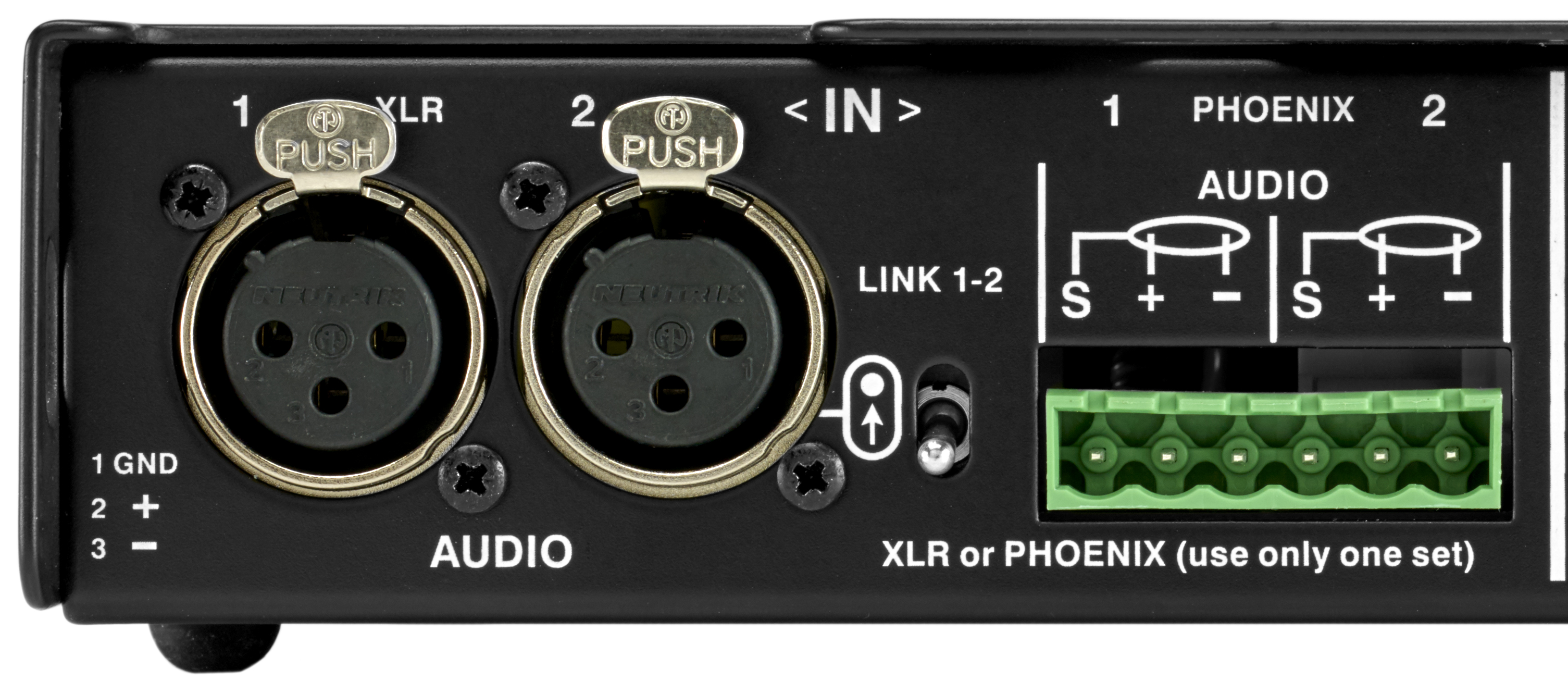
MPS-482HP Power Supply Channel Inputs
Channel inputs default to being routed to their corresponding channel outputs but channel 1 can also be routed to both outputs with the Link switch. This selection affects the input impedance (see Input Impedance for Linked Channel Inputs).
Link Switch
The Link switch determines how the two inputs are routed to the two outputs. When the Link switch is OFF (set to the down position), each input is only routed to its corresponding output (input 1 routed to output 1 and input 2 is routed to output 2).
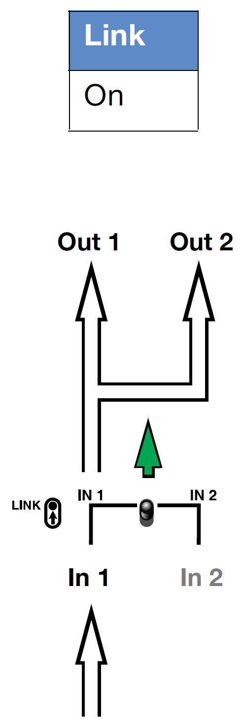
When the Link switch is ON (set to the up position), input 1 is routed to both output 1 and output 2.
Note
Input 2 is inactive when the Link switch is enabled. Connections should not be made to the inactive input.
Link Switch Routing Examples
The following examples illustrate the routing applications for the Link switch.
Routing One Input to Two Outputs
To route input 1 to both channel outputs, set Link switch to ON.
Routing Each Input to its Corresponding Output
To route each input to its corresponding channel output, set Link switch to OFF.

Input Impedance for Linked Channel Inputs
When the Link switch is enabled, channel 1 input’s unbuffered source signal is transmitted in parallel to both channel 1 and 2 outputs. This selection causes the channel input’s impedance (normally 10 kOhms for one loudspeaker) to be reduced for each linked output. For example:
one channel output, 10 kOhm input impedance
two channel outputs, 5 kOhm input impedance
Note
To avoid distortion when linking channel inputs, make sure the source device can drive the total load impedance of the linked loudspeakers. Most source devices are capable of driving loads no smaller than 10 times their output impedance. To drive two loudspeakers linked from a single channel input, the source device should have an output impedance of less than 500 ohms.
Channel Outputs
The MPS-482HP Power Supply’s two channel outputs deliver DC power (48 V DC) and balanced audio to two loudspeakers. The channel outputs are Phoenix 5-pin male connectors.
Caution
Make sure loudspeaker cables are wired correctly. For details about assembling loudspeaker cables, refer to Assembling Loudspeaker Cables.
Note
For information about cable requirements for a particular loudspeaker, refer to its operating instructions. For information about cables and cable accessories available from Meyer Sound, see MPS-482HP Power Supply Cable Accessories.
HMS-15 loudspeakers require power from both channels of the MPS-482HP Power Supply. If audio signal is present on both channels connected to an HMS-15, the signal is summed internally.
Tip
A single composite cable (such as Belden 1502 or equivalent) wired for both DC power and balanced audio can be used to connect loudspeakers to channel outputs.
MPS-482HP Power Supply Channel Outputs
The MPS-482HP Power Supply channel outputs are Phoenix 5-pin male connectors with three pins for balanced audio (positive, negative, and shield) and two pins for DC Power (positive and negative). The pins are clearly labeled on the MPS-482HP Power Supply rear panel.
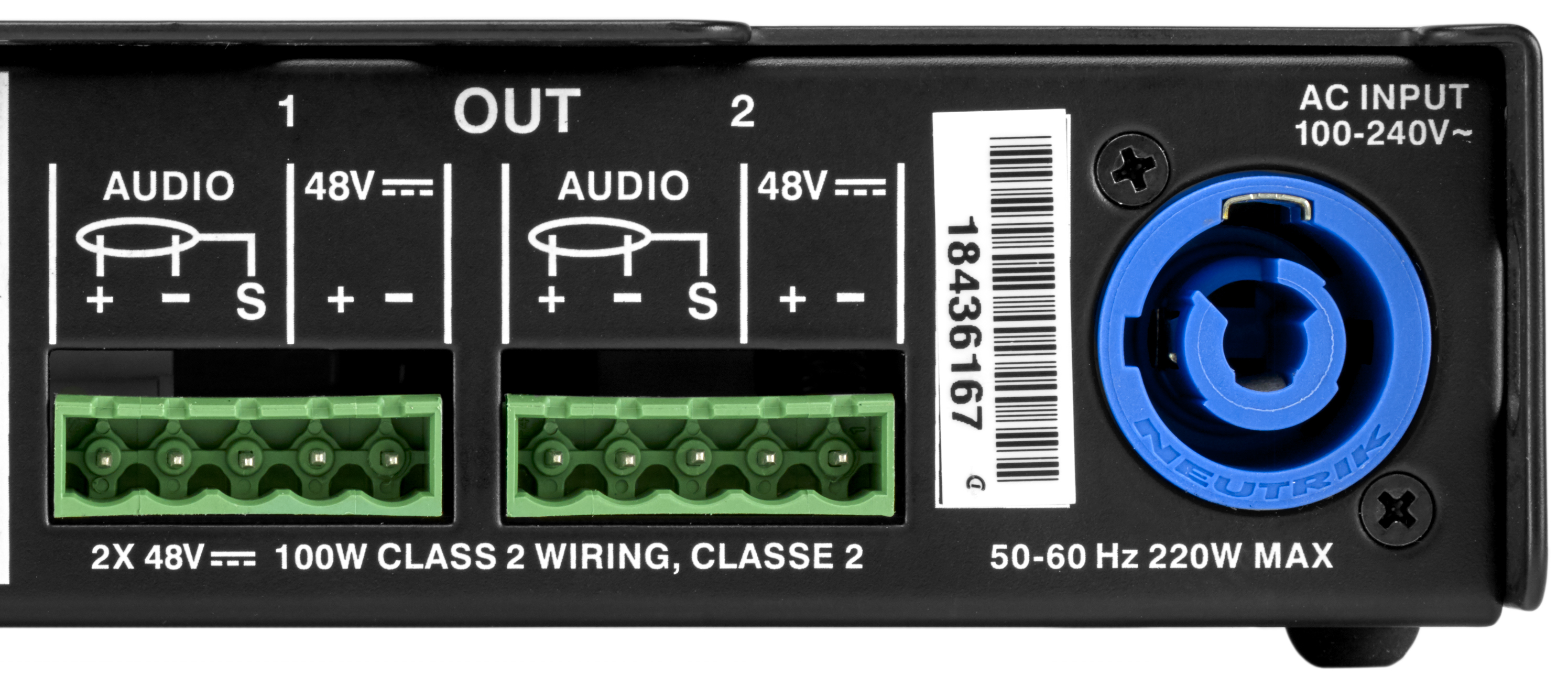
MPS-482HP Power Supply Channel Outputs
MPS-482HP Power Supply Current Draw
The current draw for the MPS-482HP Power Supply and its connected loudspeakers is dynamic and fluctuates as operating levels change. Because different cables and circuit breakers heat up at varying rates, it is important to understand the following types of current ratings and how they affect circuit breaker and cable specifications.
Idle Current: the maximum rms current during idle periods.
Maximum Long-Term Continuous Current: the maximum rms current during a period of at least 10 seconds. The maximum long-term continuous current is used to calculate temperature increases for cables to ensure that cable gauge and size conform to electrical code standards. This current rating is also used as a rating for slow-reacting thermal breakers, which are recommended for loudspeaker power distribution.
Burst Current: the maximum rms current during a period of around 1 second. The burst current is used as a rating for magnetic breakers. It is also used for calculating the peak voltage drop in long AC cable runs according to the following formula:
V pk (drop) = I pk x R (cable total)
Maximum Instantaneous Peak Current: a rating for fast-reacting magnetic breakers.
Inrush Current: the spike of initial current encountered when powering on.
The minimum electrical service amperage required by an MPS-482HP Power Supply is the sum of the maximum long-term continuous current for all loudspeakers connected to the MPS-482HP Power Supply. An additional 30 percent above the minimum amperage is recommended to prevent peak voltage drops at the service entry.
Note
For best performance, the AC cable voltage drop should not exceed 10 V, or 10 percent at 115 V and 5 percent at 230 V. Make sure that even with AC voltage drops that the AC voltage always remains within the operating window.
Electrical Safety Guidelines
Pay close attention to these important electrical and safety guidelines.
This Meyer Sound product requires a grounded outlet. Always use a grounded outlet and plug.
Do not use a ground-lifting adapter or cut the AC cable ground pin
The AC power connector must not be engaged or disengaged when under load or live.
Disconnect the mains plug before disconnecting the powerCON plug from the unit.
Keep all liquids away from the unit to avoid hazards from electrical shock.
Do not operate the unit if the power cable is frayed or broken.
Powering Loudspeakers
Note
For information about cable requirements for loudspeakers, refer to their operating instructions. For information about cables and cable accessories available from Meyer Sound, see MPS-482HP Power Supply Cable Accesories.
Caution
Make sure loudspeaker cables are wired correctly. For details about assembling loudspeaker cables, refer to Assembling Loudspeaker Cables.
Power off the MPS-482HP Power Supply.
Connect audio sources (from a mixer or processor) to the MPS-482HP Power Supply channel inputs. Use balanced XLR cables or a 3-conductor cable for balanced audio fitted into a 6-pin Phoenix connector.
Use the MPS-482HP Power Supply Link switch to route input 1 to one or both channel outputs (see Link Switch).
Connect the loudspeakers to the MPS-482HP Power Supply channel outputs. Use composite cables (such as Belden 1502 or equivalent) wired for both DC power and balanced audio and outfitted with the appropriate connectors.
When connecting loudspeakers equipped with Phoenix connectors to the MPS-482HP Power Supply, use Phoenix 5-pin female to Phoenix 5-pin female cables.
Tip
With the MPS-482HP Power Supply, using two separate cables for loudspeaker connections is also possible: a two-conductor cable for DC power and a three-conductor cable for balanced audio, both attached to a single Phoenix connector on each cable end. This approach enables use of larger gauge wires for the DC cable to achieve longer cable runs.
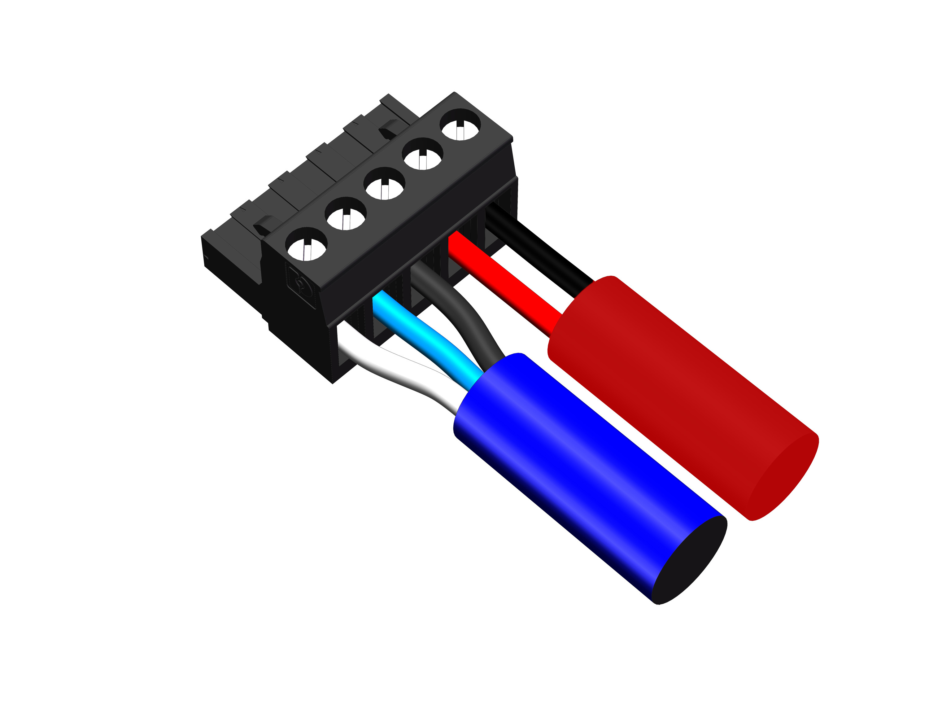
Phoenix Connector with Separate Cables
Note
HMS-15 loudspeakers require power from both channels of the MPS-482HP Power Supply. If audio signal is present on both channels connected to an HMS-15, the signal is summed internally.
When connecting loudspeakers equipped with ECO-M connectors to the MPS-482HP Power Supply, use Phoenix 5-pin female to ECO-M 7-pin female cables.
Power on the MPS-482HP Power Supply and monitor the LEDs on its front panel to verify the connections (see Fuse, Voltage, and Load Current LEDs (1–2).
Check loudspeaker LEDs to determine whether the loudspeakers are ready to reproduce audio.
Enable output from the audio source (from a mixer or processor) connected to the MPS-482HP Power Supply.
MPS-482HP Optional Power Supply Mounting Accessories
Meyer Sound offers two optional accessories to increase mounting flexibility:
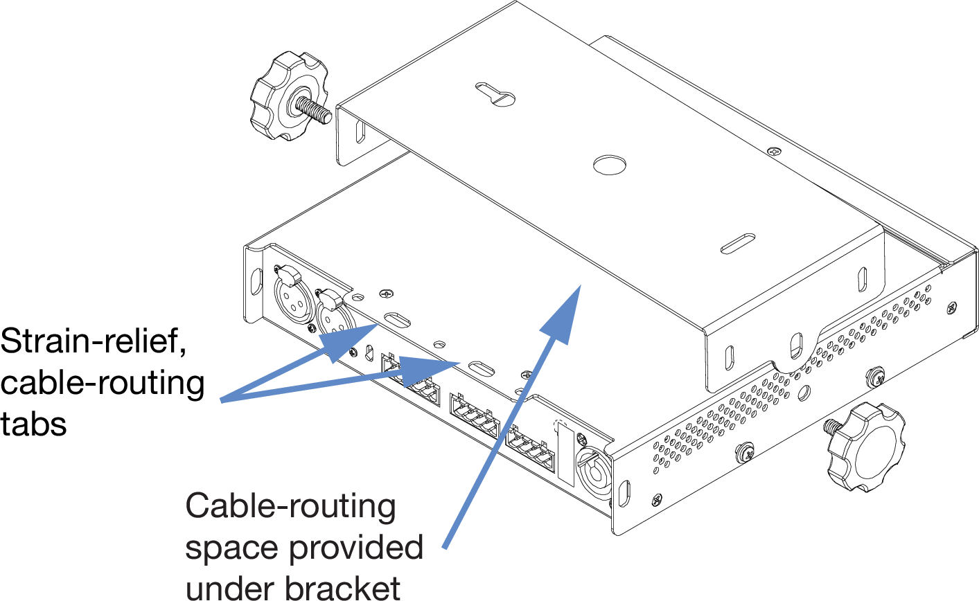
MPS-482HP Wall Bracket Kit (PN 40.285.015.01): enables mounting of one MPS-482HP Power Supply remotely on a ceiling, wall, or pole (using a third-party pole mount). Hang the power supply below the bracket, or mount the power supply on top. The bracket above power supply orientation provides space for cable routing. The enclosure design includes cable routing strain relief tabs. The bracket accommodates M6 fasteners.
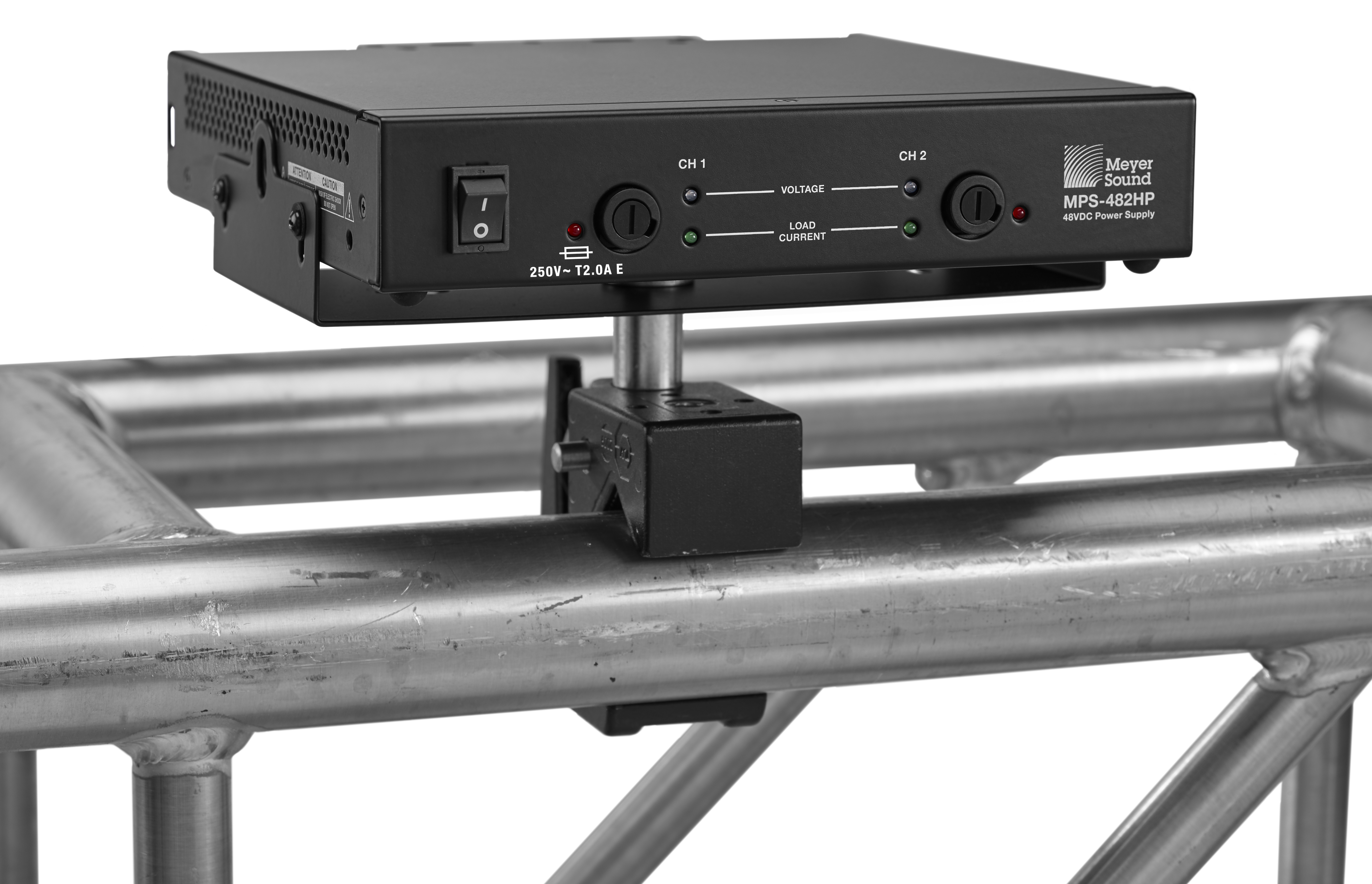
MPS-482HP Power Supply in an MPS-482HP Wall Bracket
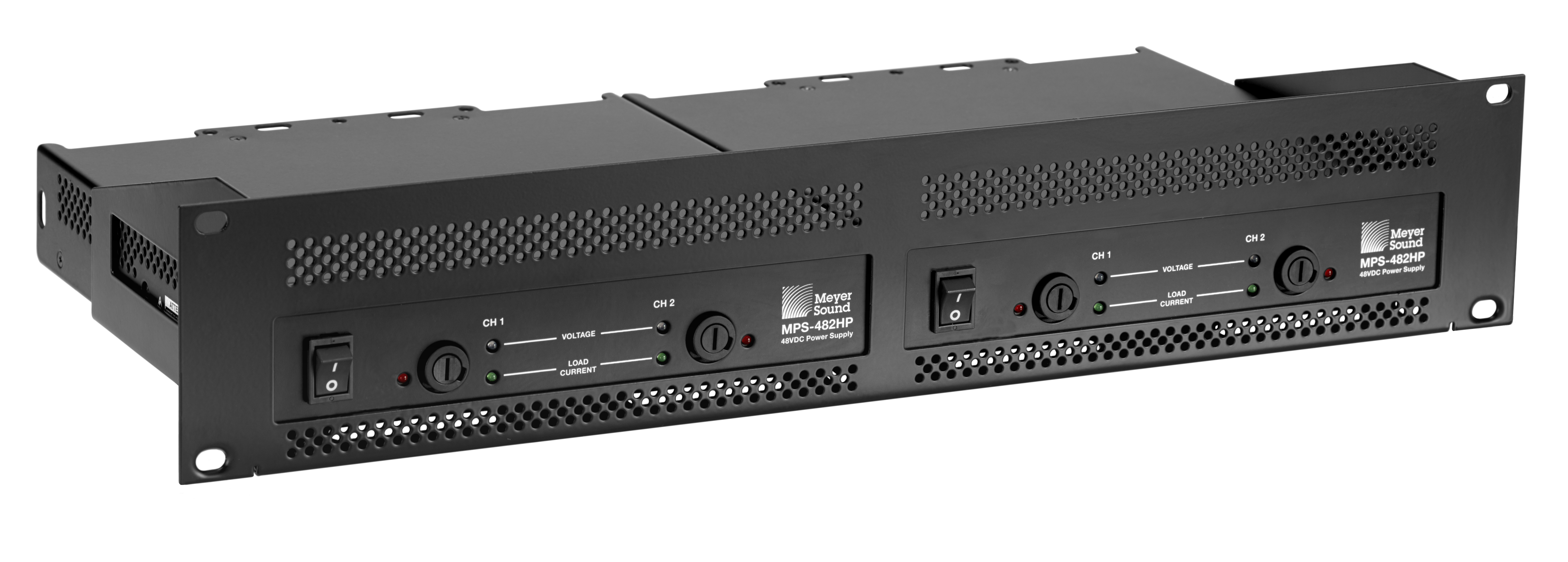
Two MPS-482HP Power Supplies in an MPS-482HP 2RU Tray
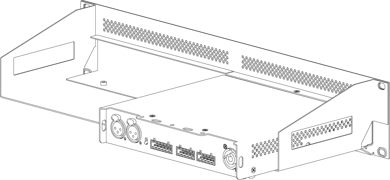
MPS-482HP 2RU Tray Kit (PN 40.285.013.01): enables mounting of one or two power supplies on a standard EIA 19-inch wide rack. The 2RU tray height facilitates cooling of the MPS-482HP Power Supply, as the area above the unit is empty. The rack mount tray comes with one face tray cover to use if one side is empty.
Rear view of MPS-482HP 2RU Tray with face cover in place on one side
MPS-482HP Power Supply Wall Bracket Cable Routing
Phoenix Loudspeaker Cables
The following Phoenix and EN3 cables are available from Meyer Sound and can be used to connect loudspeakers to an MPS-482HP Power Supply.
Note
Phoenix loudspeaker cables and bulk cable use Belden 1502R (regular) or Belden 1502P (plenum) cable. Belden 1502 is a composite cable comprising two 18 AWG wires for DC power, two 22 AWG wires for balanced audio, and one 24 AWG wire for audio shield.
Part Number | Cable | Color | Coating | Length |
|---|---|---|---|---|
524.014 | Bulk (no connectors) | Black | Regular | 500 ft (152 m) spool |
524.015 | Bulk (no connectors) | White | Plenum | 500 ft (152 m) spool |
28.163.009.41 | EN3 5-pin female to Phoenix 5-pin female | Black | Regular | 10 ft (3 m) |
28.163.009.42 | 20 ft (6.1 m) | |||
28.163.009.43 | 30 ft (9.1 m) | |||
28.163.009.44 | 50 ft (15.2 m) | |||
28.163.009.45 | 100 ft (30.5 m) | |||
28.163.009.46 | 150 ft (45.7 m) | |||
28.163.009.51 | EN3 5-pin female to Phoenix 5-pin female | White | Plenum | 10 ft (3 m) |
28.163.009.52 | 20 ft (6.1 m) | |||
28.163.009.53 | 30 ft (9.1 m) | |||
28.163.009.54 | 50 ft (15.2 m) | |||
28.163.009.55 | 100 ft (30.5 m) | |||
28.163.009.56 | 150 ft (45.7 m) | |||
28.163.009.60 | Phoenix 5-pin female to Phoenix 5-pin female | Black | Regular | 6 ft (1.8 m) |
28.163.009.61 | 10 ft (3 m) | |||
28.163.009.62 | 20 ft (6.1 m) | |||
28.163.009.63 | 30 ft (9.1 m) | |||
28.163.009.64 | 50 ft (15.2 m) | |||
28.163.009.65 | 100 ft (30.5 m) | |||
28.163.009.66 | 150 ft (45.7 m) |
Phoenix and EN3 Cable Connectors and Adapters
The following cable connectors and adapters are available from Meyer Sound.
Part Number | Connector/Adapter | Use |
|---|---|---|
484.053 | Phoenix 5-pin female cable mount connector | Connects to MPS-482HP Power Supply channel outputs and loudspeakers equipped with Phoenix connectors |
468.069 | EN3 5-pin female cable mount connector | Connects to loudspeakers equipped with EN3 connectors |
468.072 | EN3 5-pin female inline cable adapter | Connects to EN3 5-pin male cable mount connector |
468.073 | EN3 5-pin male inline cable adapter | Connects to EN3 5-pin female cable mount connectors |
468.081 | ECO-M 7-pin female cable mount connector | Connects to loudspeakers equipped with ECO-M 7-pin male panel mount connectors |
28.163.033.01 | Cable coupler EN3 5-pin female-to-male (5-inch, 0.12 m) | Joins two cables: one with an EN3 5-pin male cable mount connector to one with an EN3 5-pin female cable mount connector |
Assemble IntelligentDC loudspeaker cables
When wiring IntelligentDC loudspeaker cables, each pin in the cable must align correctly with the corresponding pin in the MPS channel output connector (see Channel Outputs). Ensure the 48 V DC from the MPS power supply connects directly (and only) to the 48 V DC pins on the loudspeaker connector, and that the polarity aligns (negative to negative, positive to positive) to prevent damage to the loudspeaker. In addition, verify the audio pin polarity, as reversals in audio signals can affect system performance.
Wire | Gauge | Signal |
|---|---|---|
Red | 18 AWG | DC power, positive (+) |
Black | 18 AWG | DC power, negative (–) |
White | 22 AWG | balanced audio, positive (+) |
Blue | 22 AWG | balanced audio, negative (–) |
Shield | 24 AWG | balanced audio, shield |
Assembling Phoenix-to-Phoenix Loudspeaker Cables
When connecting loudspeakers equipped with Phoenix connectors to the MPS-488HPp power supply, you need a Phoenix 5-pin female to Phoenix 5-pin female cable. The following procedure documents how to assemble this cable.
 |
Assembled Phoenix-to-Phoenix Cable
If the cable has not yet been stripped, strip one end of the cable. Strip the outer shielding by 1 inch and then strip the black, red, blue, and white wires by 0.275 inch.

Insert the five exposed conductors into the five cable holes in a Phoenix 5-pin female cable mount connector. Use the following wiring scheme.

Pin Destinations for Phoenix 5-Pin Female Cable Mount Connector
Secure the conductors by tightening the five screws in the Phoenix cable mount connector. Screws should be torqued to 5–6 Nm(4.4–5.3 In-Lbs).

Caution
Screws should not be inserted into the Phoenix connector while the connector rests in a mating plug. Doing so will damage the contacts. During assembly, the Phoenix connector should only be held in place externally.
Repeat the previous steps and attach the other end of the cable to another Phoenix 5-pin female cable mount connector.
Verify the wiring polarity is correct for both cable ends
Assemble Phoenix-to-EN3 cables
When connecting loudspeakers equipped with EN3 connectors to power supplies equipped with Phoenix connectors, you'll need a Phoenix 5-pin female-to-EN3 5-pin female cable like the one shown below. The following procedure describes how to assemble this cable. If starting with an EN3-to-pigtail cable, skip steps 4–7 in this procedure.

Strip the cable jacket one (1) inch and then strip the black, red, blue, and white wires by 0.275 inch.

Warning
Do not tighten screws while the connector rests in a mating plug. Doing so will damage the contacts. During assembly, only hold the Phoenix connector externally in place.
With the connector oriented as shown below (lug screws up), insert the five exposed conductors into the five cable holes of a Phoenix 5-pin female cable mount connector. Use the following wiring scheme.

Secure the conductors by tightening the five screws in the Phoenix cable mount connector torqued to 0.5–0.6Nm (4.4–5.3In-Lbs).

On the other end of the cable, strip the outer cable jacket one (1) inch and then strip the black, red, blue, and white wires 0.275 inch.
Disassemble the EN3 5-pin female connector and feed the stripped cable through the boot, cable clamp housing, and coupling ring.

Solder the five exposed conductors to the five pins on the EN3 cord connector using the following wiring scheme.
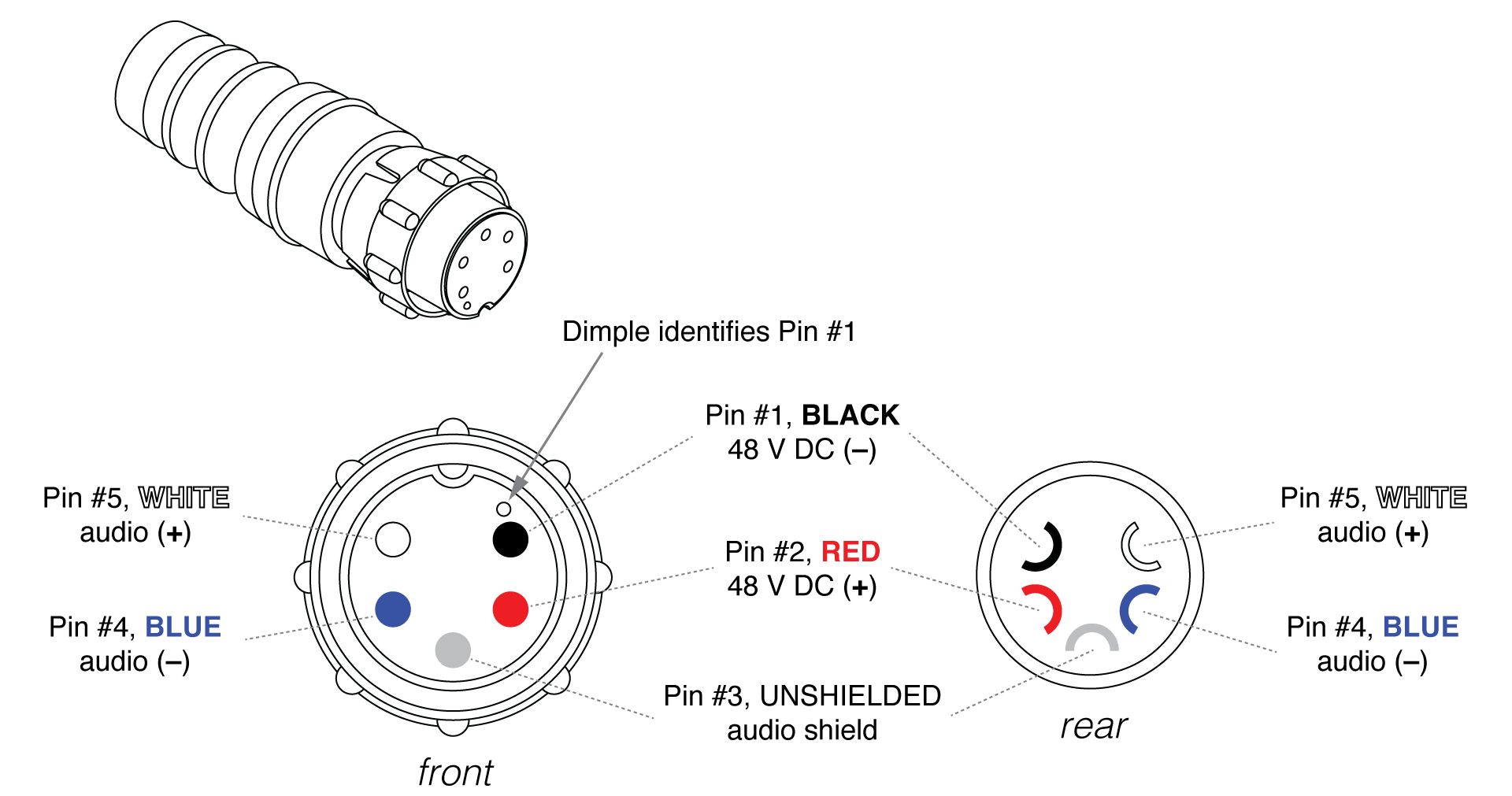
Reassemble the EN3 5-pin female connector:
Align the coupling ring’s side notches with the cord connector’s side notches and slide the coupling ring onto the cord connector.
Carefully insert the end of the cable clamp housing into the cord connector until it locks into place. Snap the cable clamps into their compartments in the cable clamp housing.
Slide the boot forward until it completely covers the cable clamp housing.
Using a continuity or impedance meter, verify that each pin on one connector connects to the corresponding pin on the other connector.
Assembling Phoenix-to-ECO-M Loudspeaker Cables
When connecting loudspeakers equipped with ECO-M connectors to the MPS-488HPp power supply, you need a Phoenix 5-pin female to ECO-M 7-pin female cable. The following procedure documents how to assemble this cable.

Assembled Phoenix-to-ECO-M Cable
If the cable has not yet been stripped, strip one end of the cable. Strip the outer shielding by 1 inch and then strip the black, red, blue, and white wires by 0.275 inch.
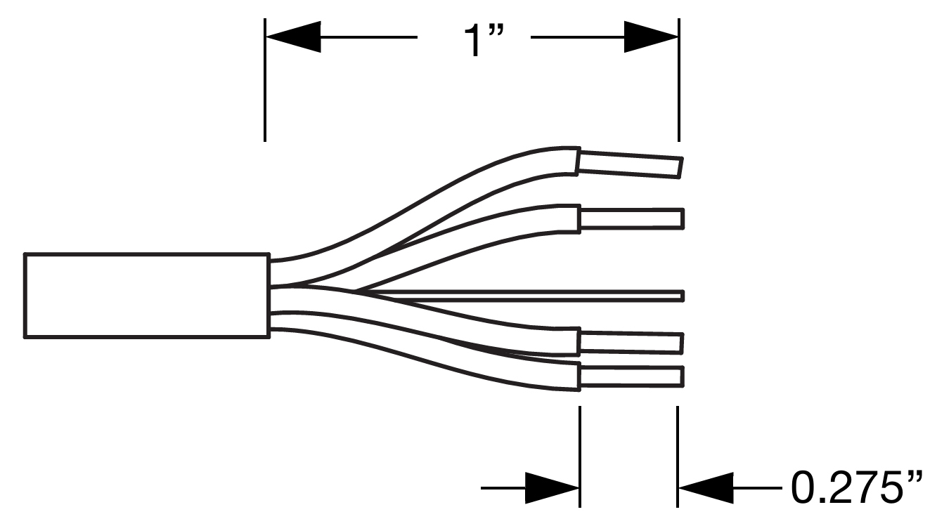
Insert the five exposed conductors into the five cable holes in a Phoenix 5-pin female cable mount connector. Use the following wiring scheme.

Pin Destinations for Phoenix 5-Pin Female Cable Mount Connector
Secure the conductors by tightening the five screws in the Phoenix cable mount connector. Screws should be torqued to 5–6 Nm(4.4–5.3 In-Lbs).
Caution
Screws should not be inserted into the Phoenix connector while the connector rests in a mating plug. Doing so will damage the contacts. During assembly, the Phoenix connector should only be held in place externally.
If the other (ECO-M) end of the cable has not been stripped, strip the outer shielding 1 inch and then strip the black, red, blue, and white wires 0.100 inch.
Disassemble the ECO-M 7-pin female connector and feed the stripped cable through the pressing screw, pinch ring, seal, angled hood, and sleeve.
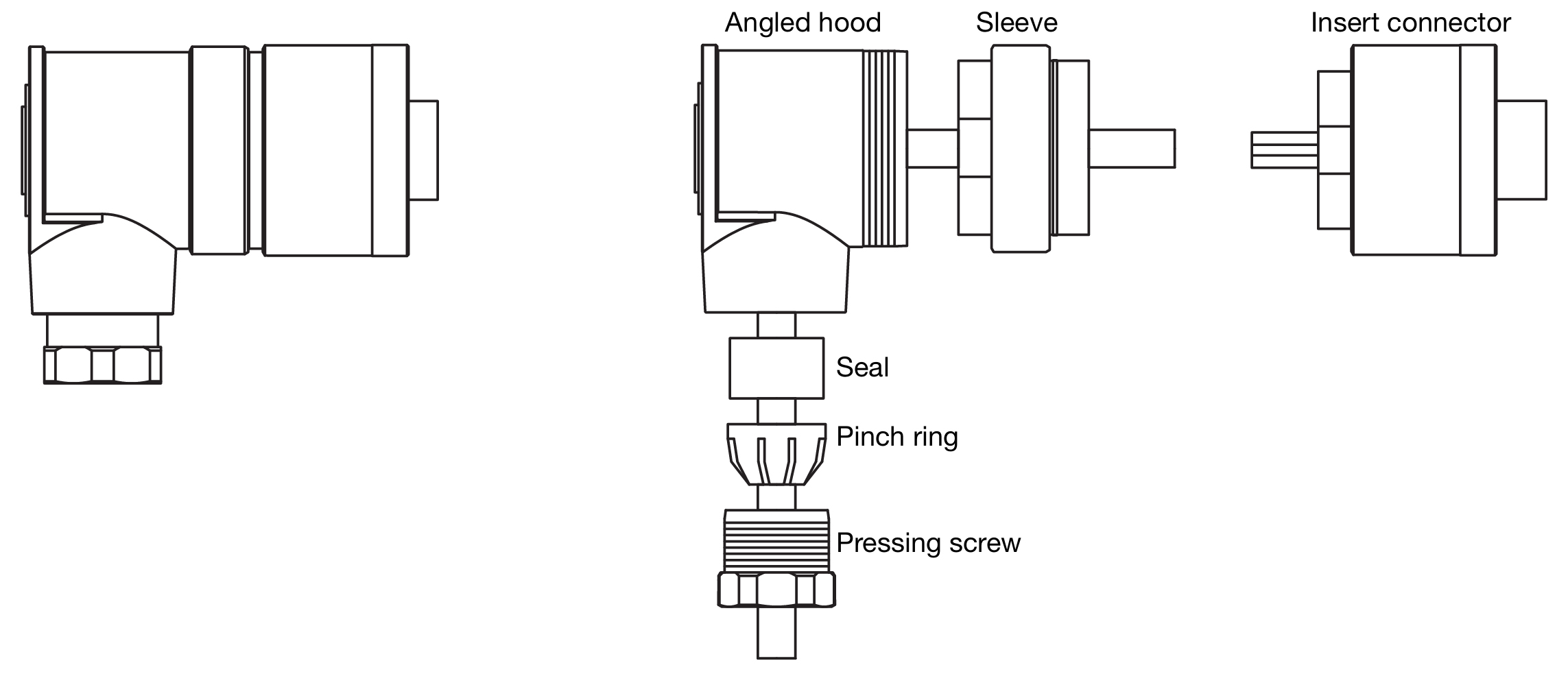
ECO-M 7-Pin Female Cable Mount Connector, Assembled (Left) and Disassembled (Right)
Fasten the five exposed conductors to the (1, 2, S, 5, and 6) pins on the ECO-M insert connector using the following wiring scheme.

Pin Destinations for ECO-M 7-Pin Female Cable Mount Connector
Reassemble the ECO-M 7-pin female connector:
Return the sleeve to the angled hood and secure it with the insert connector.
Return the seal and pinch ring to the angled hood and secure it with the pressing screw.
Verify the wiring polarity is correct for both cable ends.
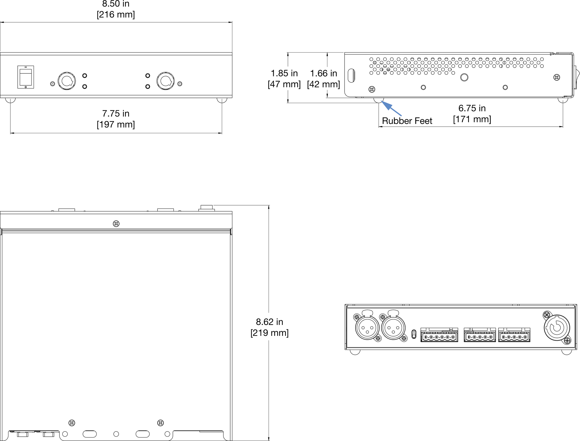
MPS-482HP Power Supply Dimensions
Federal Communications Commission (FCC) Statement
This equipment has been tested and found to comply with the limits for a Class A digital device, pursuant to part 15 of the FCC Rules. These limits are designed to provide reasonable protection against harmful interference when the equipment is operated in a commercial environment. This equipment generates, uses, and can radiate radio frequency energy and, if not installed and used in accordance with the instruction manual, may cause harmful interference to radio communications.
Operation of this equipment in a residential area is likely to cause harmful interference in which case the user will be required to correct the interference at their own expense.
This device complies with Part 15 of the FCC rules. Operation is subject to the following two conditions: (1) this device may not cause harmful interference, and (2) this device must accept any interference received, including interference that may cause undesired operation.
INDUSTRY CANADA COMPLIANCE STATEMENT
This Class A digital apparatus complies with Canadian ICES-003.
AVIS DE CONFORMITÉ À LA RÉGLEMENTATION D'INDUSTRIE CANADA
Cet appareil numérique de la classe A est conforme à la norme NMB-003 du Canada.
EN 55032 (CISPR 32) STATEMENT
Warning: This equipment is compliant with Class A of CISPR 32. In a residential environment this equipment may cause radio interference.
