Operating Instructions — ULTRA-X80
Versatile point source loudspeaker


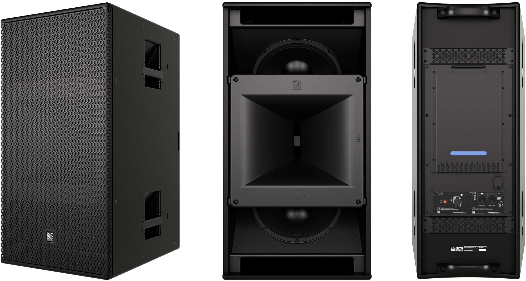
The ULTRA-X80 and ULTRA-X82 are the most capable models of the Ultra Series point source loudspeakers. These models have been designed for a variety of high-power applications. From sports arenas and stadiums to houses of worship, theaters, and live music venues, the ULTRA-X80 delivers exceptional sonic experiences for all kinds of audiences, in all kinds of venues, for all kinds of sound.
ULTRA-X80, Standard Weather Protection
Features
Constant directivity rotatable horn
Concentric driver configuration
Rigging points top and bottom for mounting and accessory attachment
Available in custom colors
Standard and Outdoor Temporary weather protection versions
The ULTRA-X80 and ULTRA-X82 have different horn dispersions, 95 x 40 degrees and 50 x 40 degrees, respectively. The horns are rotatable, allowing the cabinet to be mounted horizontally or vertically while maintaining the desired coverage.
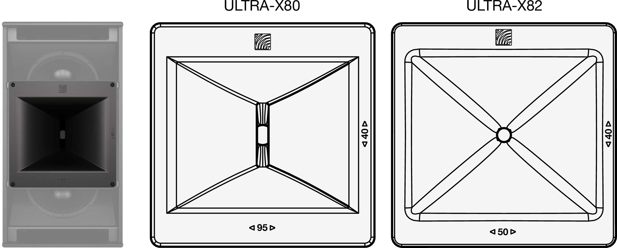
ULTRA-X80 95 x 40° and ULTRA-X82 50 x 40° Horn Dispersions
The durable trapezoidal enclosure of the ULTRA-X80 ships with a slightly textured black finish and is also available in custom colors. A powder-coated, perforated steel grille provides protection to the front of the loudspeakers. Two versions of environmental protection are available for ULTRA-X80: Standard and Outdoor Temporary. The Outdoor Temporary versions of ULTRA-X80 loudspeakers include additional treatment of the wood cabinet and the addition of stainless-steel mesh behind the grille.
The ULTRA-X80 is designed to be deployed alongside Meyer Sound LFC series products, extending the low-frequency performance (see Adding Low-Frequency Models).
Meyer Sound’s Galileo GALAXY signal processors typically provide signal processing and routing between mixing consoles or other source devices and the loudspeakers. In addition to the expected signal processing, the Galileo GALAXY 816 and 408 processors include additional filters and functions unique to Meyer Sound products.
The high-output switch-mode power supply reduces weight and is more efficient than linear power supplies. The operating voltage is 200-240 V AC, 50-60 Hz. When an appropriately sized and specified branch circuit breaker is in line, multiple ULTRA-X80 loudspeakers can be connected to one circuit (see AC Power Distribution).
Both analog and Milan AVB audio inputs are provided on the user panel (see Audio Inputs). The connectors provided are from Neutrik’s TRUE1 TOP (True Outdoor Protection) product line. An IP65 rating is achieved for the connectors only when the connected cables are also terminated with Neutrik TRUE1 TOP connectors or when the sealing caps are properly seated when not in use. Each loudspeaker ships with Neutrik TRUE1 TOP cable-mount connectors that mate with the user panel connectors (AC inlet, analog audio, and network).
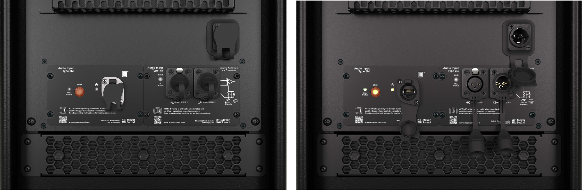
ULTRA-X80 Loudspeaker User Panel, Seated Sealing Caps (left), Open Sealing Caps (right)
Meyer Sound’s Nebra software displays the telemetry data of ULTRA-X80, which is transmitted via the network connection. Nebra includes the functionality to manage the digital connections between Milan AVB-capable source devices and Milan Endpoint-equipped loudspeakers.
High-resolution acoustic datasets for ULTRA-X80 loudspeakers are available in Meyer Sound’s MAPP 3D System Design and Prediction software.
Optional rigging accessories include both a yoke and u-bracket, enabling safe suspension of the loudspeaker. The MY-T1 Yoke and the MUB-T1 U-Bracket accessories allow for several mounting options and are available in custom colors.
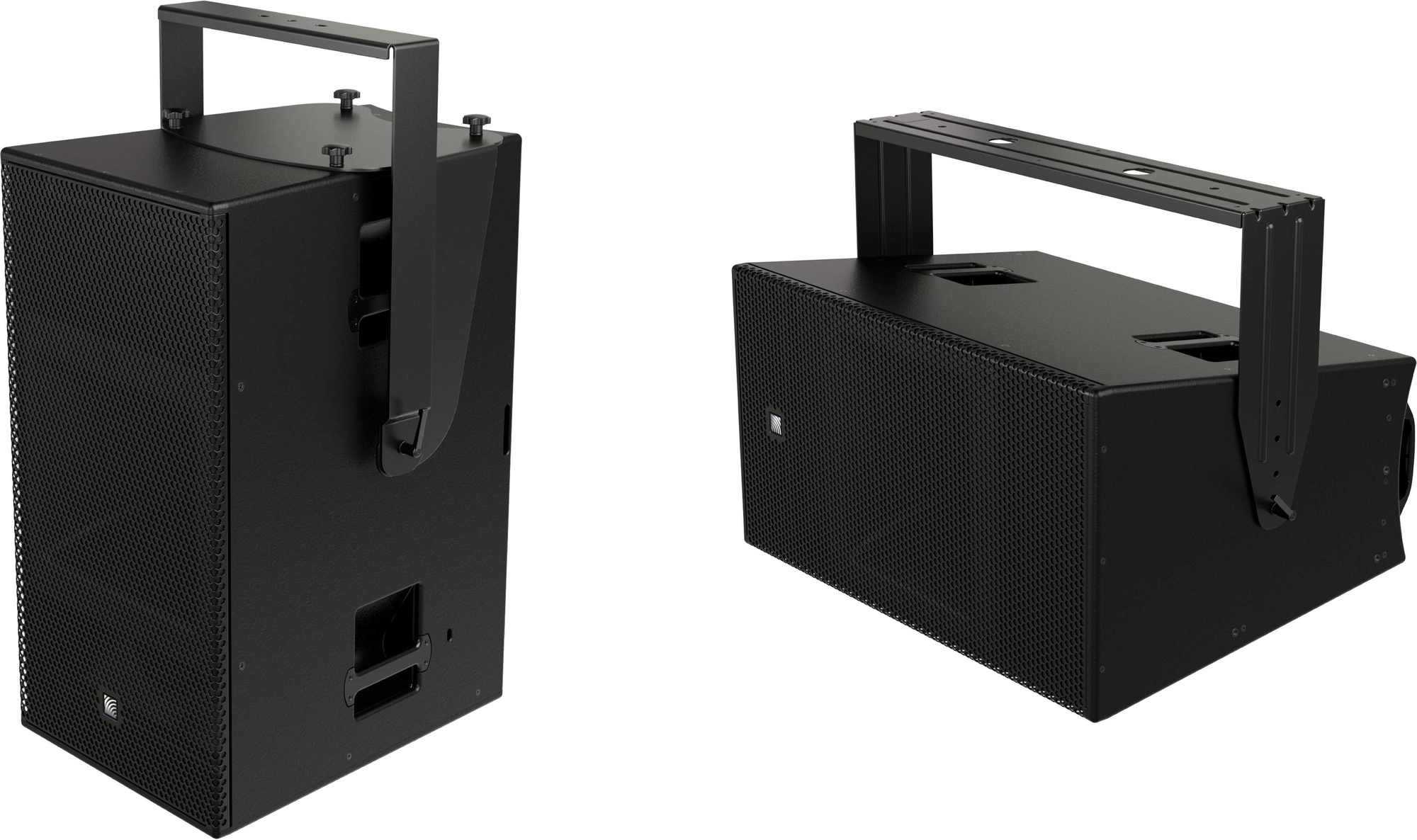
MY-T1 Yoke, and MUB-T1 U-Bracket
Power Requirements
Understanding power distribution, voltage, and current requirements, and electrical safety guidelines is critical to the safe operation of ULTRA-X80 loudspeakers.
Sufficient power must be provided for ULTRA-X80 loudspeakers to accurately reproduce the full dynamic range of the input signal, especially during periods of maximum acoustic output.
AC Power Distribution
All components in an audio system (self-powered loudspeakers, mixing consoles, and processors) must be properly connected to an AC power distribution system, ensuring that AC line polarity is preserved. All the grounding points of the audio system components must be connected to a single node or common point using the same cable gauge (or larger) as the Neutral and Line conductors.
Caution
The nominal operational AC mains voltage range is 200–240 V AC, 50-60 Hz.
For a LINE-NEUTRAL-EARTH/GROUND supply configuration, the voltage between the Line and Earth/Ground should never exceed 264 V AC, or be less than 160 V AC to prevent damage to the loudspeaker or unintended power cycling.
When using a Single-Line AC wiring (LINE - NEUTRAL - EARTH/GROUND), before applying AC power to any Meyer Sound self-powered loudspeaker, make sure the voltage potential difference between the Neutral and Earth/Ground conductors is less than 5 V AC.
The Earth/Ground conductor must always be used for safety reasons.
Improper Earth/Grounding of connections between loudspeakers and the rest of the audio system may produce noise or hum or cause serious damage to the input and output stages of the system’s electronic components.
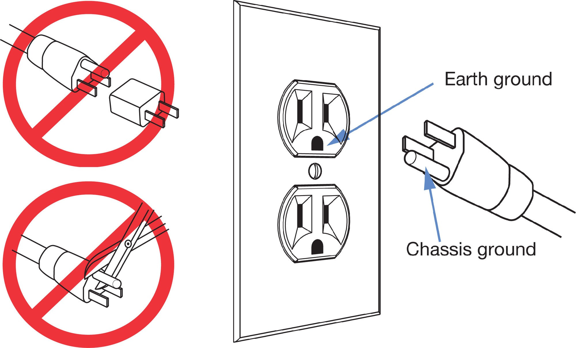
Always Ensure the Earth/Ground Conductor in Each Plug and Socket is Correctly Connected
Branch Circuits
To reduce the number of branch circuits, it is common to connect multiple ULTRA-X80 loudspeakers to one branch circuit, provided the circuit breaker is sufficiently rated. To reduce the impedance of the conductors, minimize the length of cable after the branch circuit has been “split.” Typically, a single circuit is split very near the loudspeakers using a molded split, junction box, or wye cable.
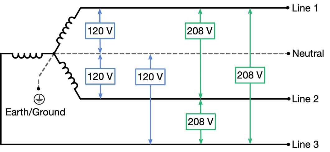
120 V AC, 3-Phase Wye System (Two Lines)
Line-Line-Earth/Ground
The figure below illustrates the secondary of a 120/208 V AC, 3-phase Wye distribution system. Each loudspeaker is connected to two Lines and Earth/Ground. This configuration is possible because ULTRA-X80 loudspeakers tolerate elevated voltages from the Earth/Ground conductor and do not require a Neutral line. This distribution system delivers 208 V AC to each loudspeaker.
Caution
Do not connect ULTRA-X80 loudspeakers to only one Line of a 120/208 V AC Wye service as the voltage delivered to the loudspeaker will be 120 V AC, below the 160 V AC minimum operating voltage.
 |
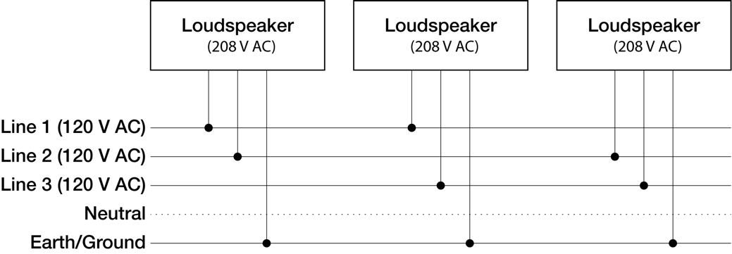
Three-Phase, 120/208 Volt AC Transformer Secondary, Wye Configuration and Loudspeaker Connections
230 V AC, 3-Phase Wye System (Single Line)
Line-Neutral-Earth/Ground
The figure below illustrates the secondary of a 230/400 V AC, 3-phase Wye distribution system. Each loudspeaker is connected to one of the Lines, the Neutral, and the Earth/Ground. This distribution system delivers 230 V AC to each loudspeaker.
Caution
For 230/400 V AC, 3-phase Wye systems, never connect two Lines to the AC inlet of an ULTRA-X80 loudspeaker. The inlet would receive 400 V AC, significantly exceeding the 264 V AC upper voltage limit and damaging the loudspeaker.
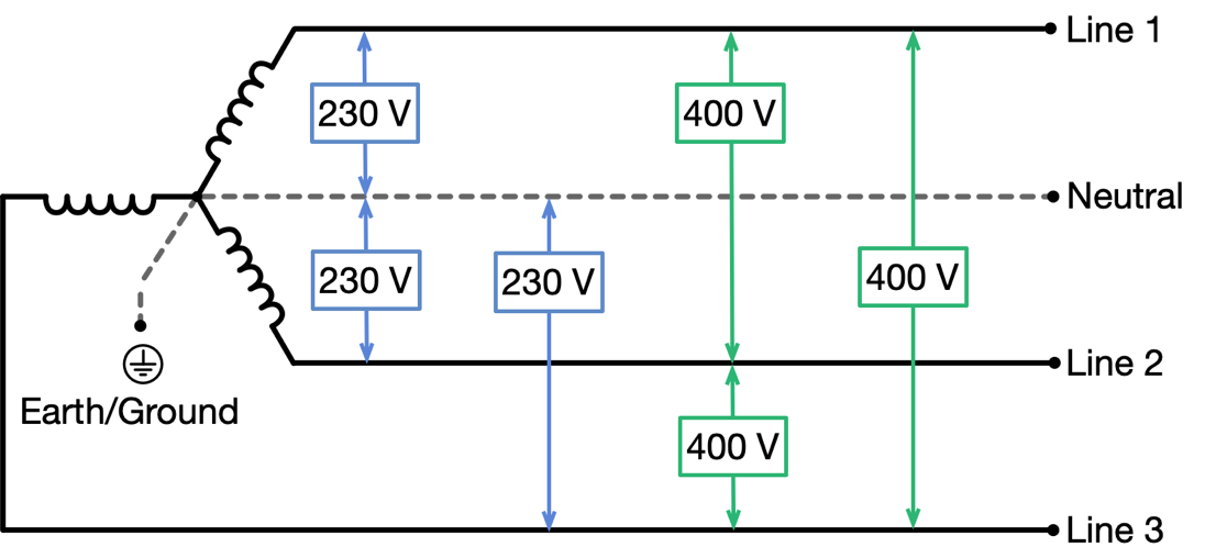
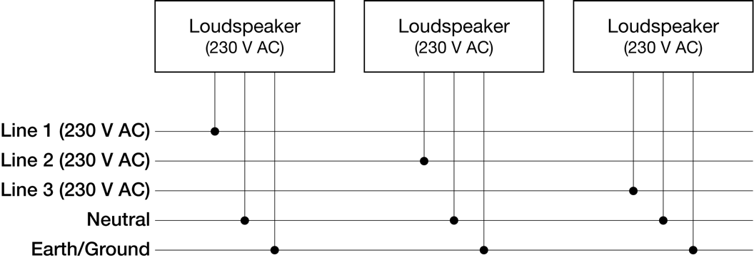
Three-Phase, 230/400 Volt AC Transformer Secondary, Wye Configuration and Loudspeaker Connections
AC Inlet
The user panel of an ULTRA-X80 loudspeaker includes an AC inlet connector, a 3-conductor Neutrik powerCON TRUE1 from the TOP (True Outdoor Protection) line. This locking connector supplies electrical power to the loudspeaker, as shown in the figure below.
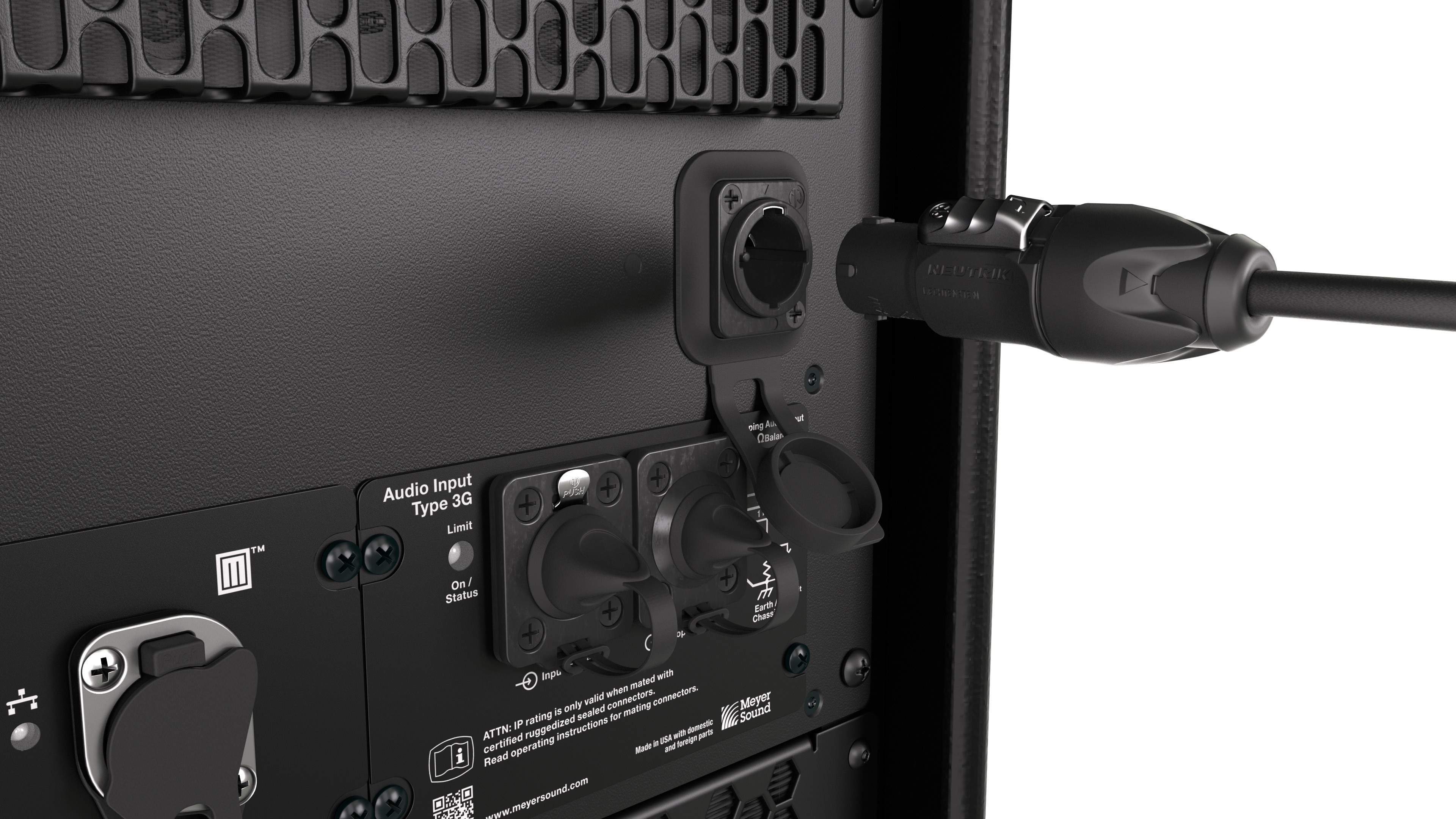
User Panel, Power Inlet, Neutrik powerCON TRUE1 TOP Connector
The powerCON TRUE1 TOP connectors are rated to be engaged/disengaged while under load or while the circuit is energized without damaging the connectors.
The inlet connector is certified for outdoor protection (IP65, UL50E) only when mated with a Neutrik powerCON TRUE1 TOP cable-mount connector or when the connector is not in use and the sealing cap is fully inserted.
Caution
Before connecting the power cable, make sure the AC inlet connector assembly is secure and has not been damaged during prior use or transportation.
Do not operate the loudspeaker if the power cable is frayed or broken.
Check the sealing cap for moisture before covering the connector. If wet, dry the cap before covering the connector to avoid introducing liquid into the connector.
Always seal the connector with the sealing cap when the connector is not in use.
Always replace sealing caps if they become damaged or are leaking.
Power Cable Assembly
A cable-mount Neutrik powerCON TRUE1 TOP connector (NAC3FX-W-TOP, female cable mount) is included with each ULTRA-X80 loudspeaker, enabling users to assemble power cables to meet their needs.
Caution
The power cable conductors must be 12 AWG (2 mm²). Use only cable with an outer jacket diameter between 1/4-in [6.4 mm] and 1/2-in [12.7 mm]. For the inlet end of the cable, use a plug type that is rated for at least 16A, 250 V AC, and is approved for use in the region where the product will be used. The size of the conductors is specified to reduce the conductor impedance, which minimizes voltage sag when the acoustic output of the loudspeaker approaches its maximum acoustic output.
The pins of the powerCON TRUE1 TOP cable mount connector are labeled as follows:
• L (Line)
• N (Neutral)
•  (Protective Earth/Ground)
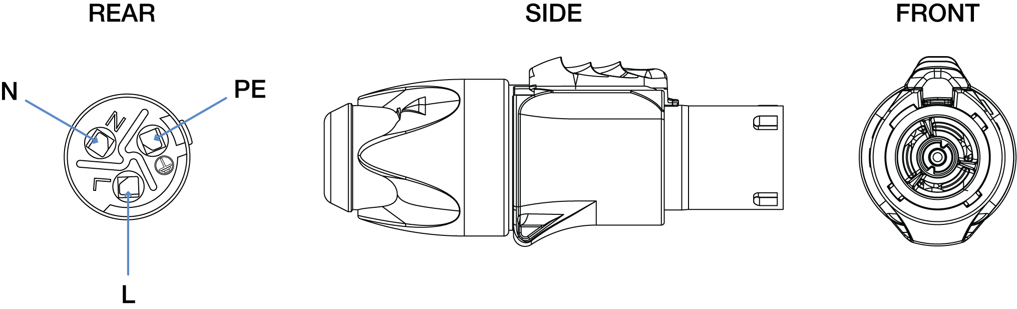
Neutrik powerCON TRUE1 TOP Cable Mount Connector
Note
Visit the Neutrik website (neutrik.com) to download the cable preparation and connector assembly instructions for the powerCON TRUE1 TOP cable-mount connector.
Caution
Careful attention should be paid when terminating these connectors to ensure the proper conductor of the cable is connected to the intended terminal. The terminal identification markings inside the connector can be difficult to identify. After terminating the cable conductors, we strongly advise using a continuity meter to verify the proper connections are made, preventing a shock hazard and/or damage to the loudspeaker.
How AC power cables are wired is determined by the type of AC power distribution system used (see AC Power Distribution)
Caution
When wiring AC power cables and distribution systems, it is important to preserve AC line polarity and connect the Earth/Ground at both ends of the cable.
Voltage Requirements
The AC mains voltage at the loudspeaker AC inlet must be within 200 V AC and 240 V AC while the loudspeaker is operating, including periods of peak acoustic output when the loudspeaker draws maximum current. Momentary voltage drops down to 160 V AC will be tolerated without powering off but may negatively impact linear performance.
Because ULTRA-X80 loudspeakers behave as a constant power load when TPL (True Power Limiting) is engaged, current increases if the voltage decreases at its AC inlet. The maximum roundtrip resistance of the power cable for a single ULTRA-X80 loudspeaker should not exceed 5 Ohms for a 230 V AC source voltage because the AC Mains voltage may fall below 160 V AC at the AC inlet when TPL is engaged or when audio burst or peak power are high.
Caution
ULTRA-X80 loudspeakers may be damaged or malfunction if the inlet voltage is greater than 264 V AC or less than 160 V AC.
Circuit Breaker Requirements
The circuit breakers used in our power distribution modules are well suited for use with ULTRA-X80 loudspeakers and other Meyer Sound products:
European, ETI model number: KZS-1M 1p+N A C16/0.03, 6kA, which includes an RCD (residual current device) with a C-type tripping time constant and 30 mA RCD.
US, Eaton model: QCR2020 - CIRCUIT BREAKER 2-Pole, 20 A, 120/240 V AC
Circuit protection devices for main and branch circuits of any power distribution system used in conjunction with ULTRA-X80 loudspeakers should use similarly specified devices to avoid nuisance tripping. Both of the recommended devices are thermal breakers with long time constants, unlike magnetic breakers with short time constants.
Circuit sizing is based on the Maximum Long-Term Power, 900 Watts. Using Ohm’s law, the amperage can be determined based on the supplied voltage, required to be between 200 to 240 V AC. The online Amperage/BTU calculator is helpful in determining the total system current draw and thermal dissipation: https://meyersound.com/amperage-btu-calculator/.
Note
Many residual current circuit breakers (RCCB) are sensitive to high-frequency noise in the Line-Neutral path and may false/nuisance trip. If required, make certain the RCCBs are not sensitive to high-frequency noise or artifacts. Line-to-Earth/Ground and Neutral-to-Earth/Ground capacitance can cause an imbalance between the current-carrying conductors in a cable or a conduit, potentially causing RCCB nuisance tripping. Consult with a licensed electrician or electrical engineer when designing electrical distribution systems.
Power Supply
The power supply included in ULTRA-X80 loudspeakers prevents high inrush currents with soft-start power up, suppresses high-voltage transients up to several kilovolts, and filters common mode and differential mode radio frequencies (EMI).
Powering on ULTRA-X80 Loudspeakers
When powering on ULTRA-X80 loudspeakers, the following startup events take place over several seconds:
The On/Status LEDs flash during initial startup.
When both of the On/Status LEDs turn solid green, the loudspeaker is unmuted and ready to reproduce audio.
Caution
If the On/Status LEDs do not turn solid green after 15 seconds, disconnect the AC power and verify that the supply voltage is within the operating voltage range, 200-240 V AC, and the conductors of the power cable are connected to the proper terminals of the connectors.
Amplification and Audio
The ULTRA-X80 includes two audio input types, analog and Milan AVB digital audio.
ULTRA-X80 User Panel
Both audio inputs are always active. If signal is present at both inputs, they are summed and reproduced, which can lead to undesired results. For example, if the Milan AVB and analog input signals are identical for backup purposes but are not time aligned, comb filtering will occur if both signals are present at the loudspeaker inputs. When using one input as a backup to the other, utilizing the output mutes of upstream signal processing is one strategy to switch between input types.
The analog and Milan AVB inputs will arrive at the loudspeaker at different times due to the transport time of the Milan AVB signal through the network, usually less than two milliseconds. The latency of the Milan AVB signal is dependent on the number of network switch hops and the Presentation Time, which is set in software.
To synchronize the audio reproduction of analog and Milan AVB inputs, measure the acoustic output with an FFT analyzer. Measure and store the phase response when only the Milan AVB input is receiving signal. While only the analog input is receiving signal, add delay to the analog signal processing until both phase responses match.
When one input is used as a backup, synchronizing it with the primary input provides a smoother transition when the signal to the primary input is muted and the backup is unmuted. Synchronizing the inputs also preserves the time alignment with other components of the system, regardless of which input is receiving signal.
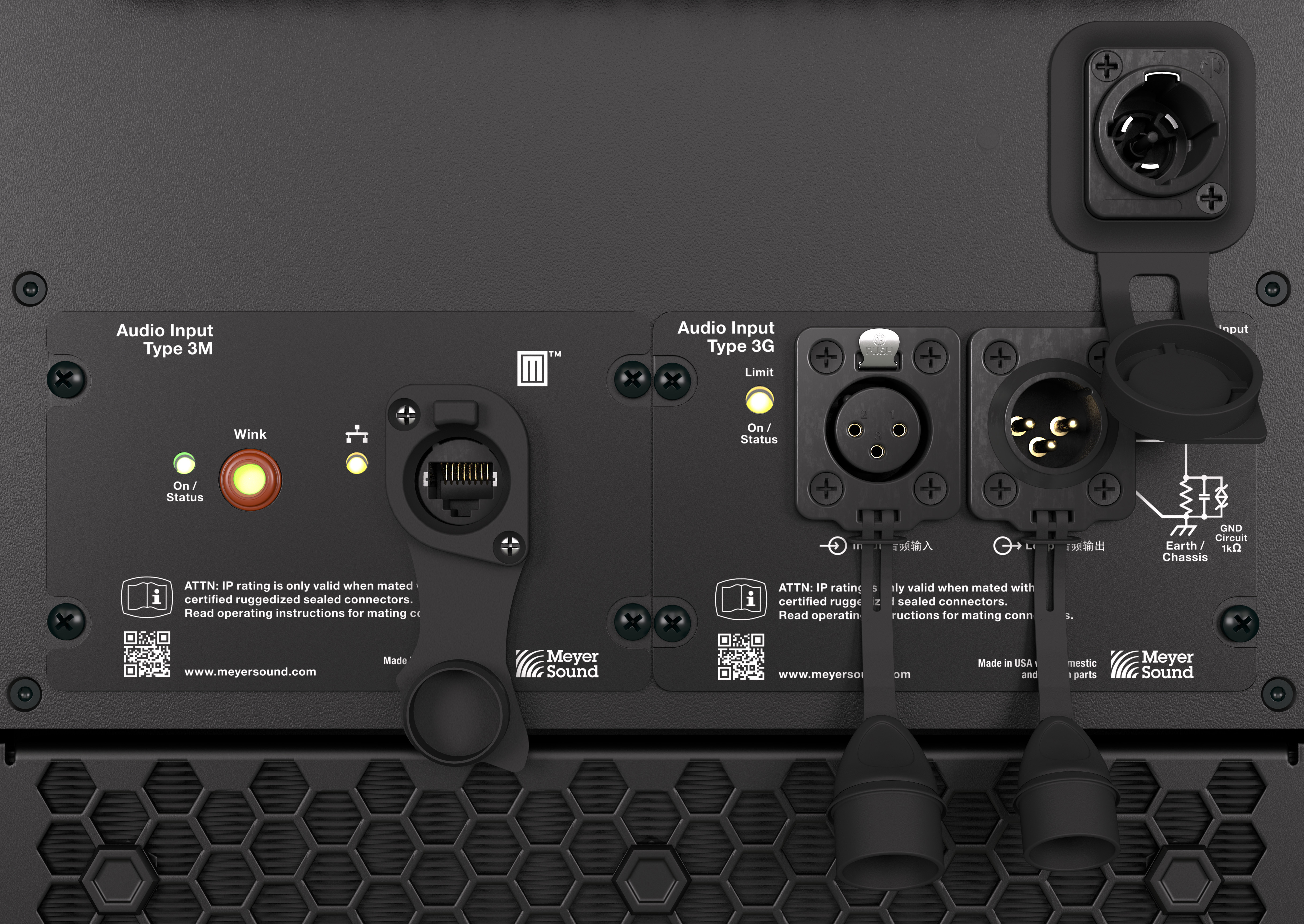
Audio Inputs
The user panel includes two 3-pin Neutrik XLR True Outdoor Protection (TOP) connectors for analog audio input and audio loop output. The network connector is a Neutrik etherCON True Outdoor Protection (TOP), which provides connection to Milan AVB-capable output devices, including Galileo GALAXY processors, typically via Avnu-certified network switches.
Caution
The analog and network chassis connectors are rated for outdoor protection (IP65, UL50E) only when mated with the Neutrik TOP cable-mount connectors, or the sealing caps are fully inserted.
Check the sealing caps for moisture before covering the connectors. If wet, dry the caps before covering the connectors to avoid introducing liquid into the connectors.
Always seal the connectors with the sealing caps when the connectors are not in use.
Always replace sealing caps if they become damaged or are leaking.
Analog Audio Input (3-Pin XLR Female)
The 3-pin XLR female Input connector accepts balanced audio signals with an input impedance of 10 kOhm. The connector uses the following wiring scheme:
• Pin 1 — 1 kOhm to chassis and Earth/Ground (ESD clamped)
• Pin 2 — Signal (+)
• Pin 3 — Signal (–)
• Case — Earth (AC) ground and chassis
Pins 2 and 3 carry the input as a differential signal. Pin 1 is connected to Earth/Ground through a 1 kOhm, 1000 pF, 15 V clamped network. This circuitry provides a virtual ground lift for audio frequencies while allowing unwanted signals to bleed to ground. Make sure to use balanced XLR audio cables with pins 1, 2, and 3 connected on both ends. Connecting the signal ground at only one end is not recommended. Shorting the signal ground conductor to the connector case may cause a ground loop, resulting in hum.
Note
If unwanted noise or hiss is produced by the loudspeaker, disconnect the audio signal cable from the loudspeaker input. If the noise stops, there is most likely nothing wrong with the loudspeaker. To locate the source of the noise, check the audio cable, source audio, AC power, and electrical ground.
Analog Audio Loop Output (3-Pin XLR Male)
The 3-pin XLR male Loop output connector allows multiple loudspeakers to be looped from a single audio source. The Loop output connector uses the same wiring scheme as the Input connector. For applications that require one drive line to provide signal to multiple loudspeakers, connect the Loop output of the first loudspeaker to the Input of the next loudspeaker, and so forth.
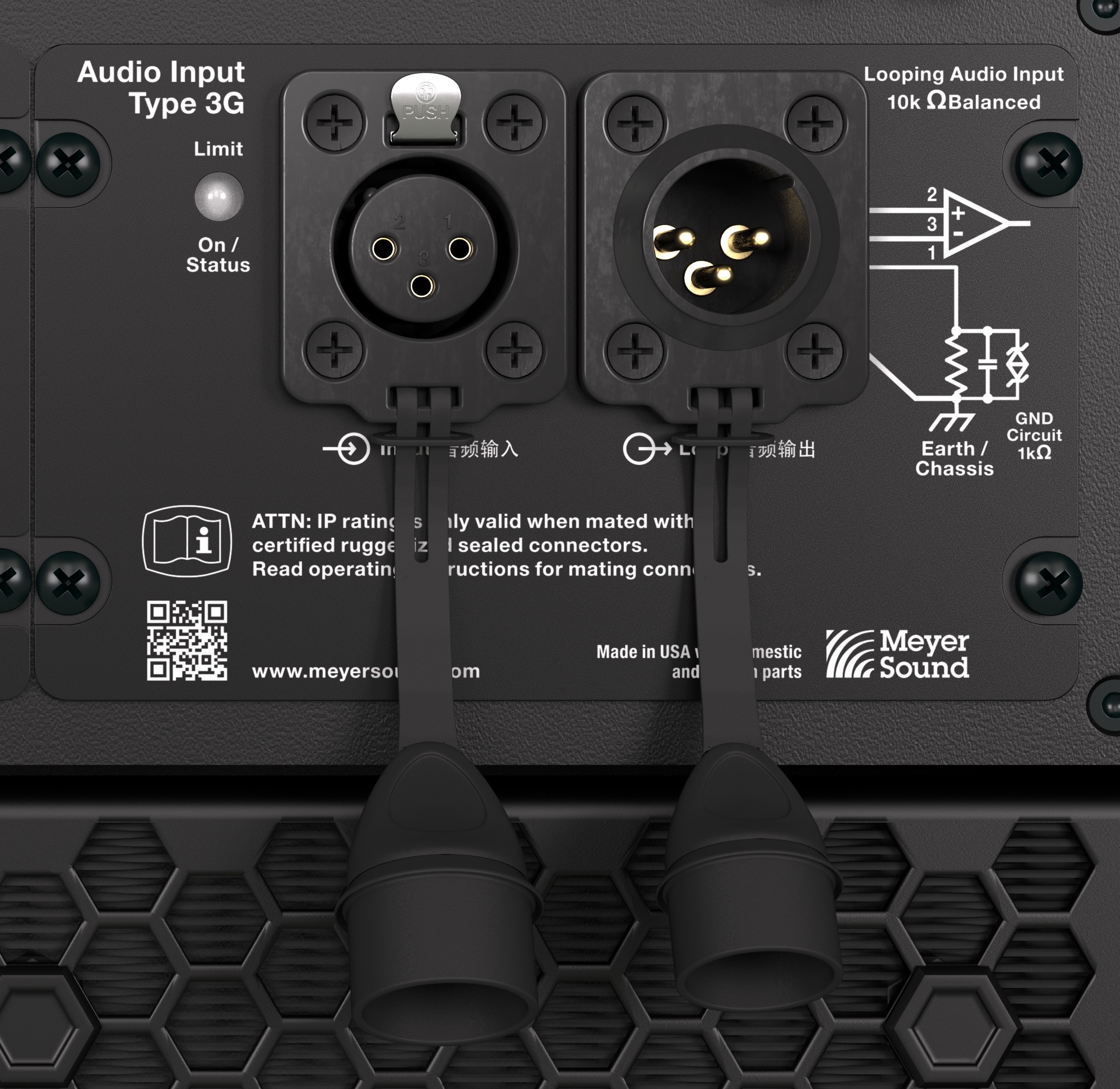
Analog Input and Loop Connectors
Caution
Make sure that all cabling for looped loudspeakers is wired correctly (Pin-1 to Pin-1, Pin-2 to Pin-2, and so forth) to prevent the polarity from being reversed. If one or more loudspeakers in a system have reversed polarity, frequency response, and coverage will be significantly degraded.
Note
The Loop output connector is wired in parallel to the Input connector and transmits the unbuffered source signal even when the loudspeaker is powered off.
Calculating Analog Input Load Impedance
To avoid distortion when looping multiple loudspeakers, make sure the source device can drive the total impedance load of the looped loudspeakers. In addition, the source device must be capable of producing +24 dBU into 50 Ohms to produce the maximum peak SPL over the operating bandwidth of the loudspeaker.
Note
Most source devices are capable of driving loads no less than 10 times their output impedance. The output impedance of third-party processors and mixing consoles typically range from 50 to 2000 Ω.
Tip
The analog outputs of Meyer Sound’s Galileo GALAXY signal processors have an output impedance of 50 Ω. Each output can drive up to 20 Meyer Sound (10 kΩ input) loudspeakers without distortion.
To calculate the load impedance for the looped loudspeakers, divide 10 kΩ (the input impedance for a single loudspeaker) by the number of looped loudspeakers. For example, the load impedance for ten ULTRA-X80 loudspeakers is 1000 Ω, (10 kΩ / 10). Most source devices are capable of driving loads no less than 10 times their output impedance. To drive this number of looped loudspeakers, the source device should have an output impedance of 100 Ω or less (1000 Ω / 10).
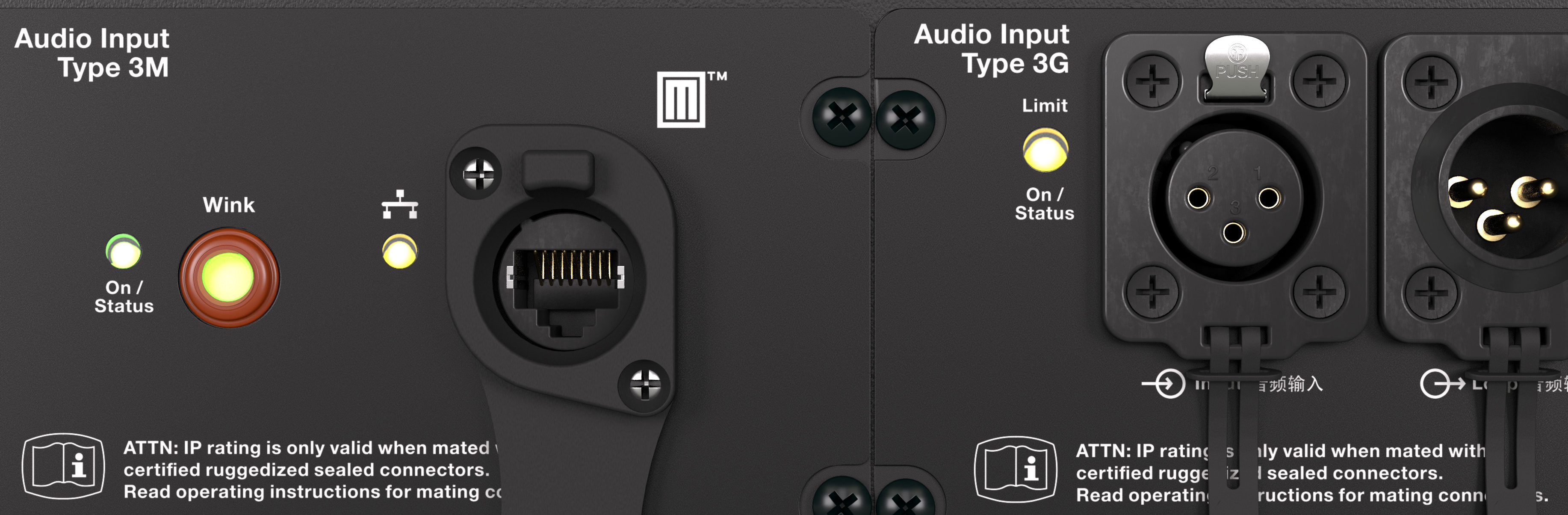
Network Connector
The user panel includes a Milan Endpoint (MEP) module which includes a Neutrik etherCON TOP connector, an Ethernet connectivity LED, an On/Status LED, and a Wink button/LED, as shown in the figure below.

Type 3M Milan Endpoint Module, On/Status LED, Wink Button/LED, Network Connection LED, and Network Connector
The etherCON TOP connector provides the network connection for both a Milan AVB digital audio input signal and the transmission of telemetry data.
The Milan Endpoint connects to a single channel of a Milan AVB digital audio stream as specified by the Avnu Alliance. To utilize the Milan AVB input, connect the loudspeaker to an Avnu-certified network switch that is also connected to the source device. See avnu.org for the current listing of certified AVB network switches.
The telemetry data of the loudspeaker is also transmitted via this connector, which is displayed in Meyer Sound’s Nebra software. An Avnu-certified network switch is not necessary when the network connection is only used to transmit telemetry data. The speed of this network connection is 100 bT, 100 Mb/second.
Digital Audio Input
When a Milan Endpoint loudspeaker and a computer are connected to the same network via an Avnu-certified network switch, the loudspeaker will be listed in Meyer Sound’s Nebra software, where Milan AVB connections are established. The Milan Endpoint loudspeaker must be assigned to an available audio source channel (Talker) as a Listener for the loudspeaker to reproduce the audio transmitted by the Talker.
The speed of the connection between the last network switch and a Milan Endpoint is 100 bT, 100 Mb/ second. The connection speed between network switches transporting Milan AVB digital audio signals is 1000 bT, 1 Gb/second.
Telemetry
Loudspeakers with Milan Endpoints transmit telemetry data via the network connection. Nebra software displays system status and performance data for each loudspeaker, including amplifier voltage, limiting activity, power output, fan speed, and driver status. Mute and identification functions are also available.
Tip
When the Milan AVB input is not used, a standard Ethernet network (IEEE 802.3 compliant, supporting at least 100 bT, 100 MB/s, full duplex) is capable of transmitting the telemetry data.
Wink Function
The Wink function facilitates the identification of physical loudspeakers that are listed in Meyer Sound’s Nebra software. When routing digital audio signals in software, it is helpful when the loudspeaker name indicates which physical loudspeaker will receive the signal.
There are three locations Wink is indicated: in Nebra software, the Wink button/LED on the user panel of the loudspeaker, and the LED bar on the rear panel. Once the Milan Endpoint has been discovered in Nebra software, the icons within the loudspeaker’s detail page include a button with an icon of an eye. Double-clicking the icon in Nebra software toggles the Wink function. When the Wink function is active, the Wink button/LED on the user panel of the loudspeaker and the rear LED bar illuminate. The Wink function times out after 10 seconds.
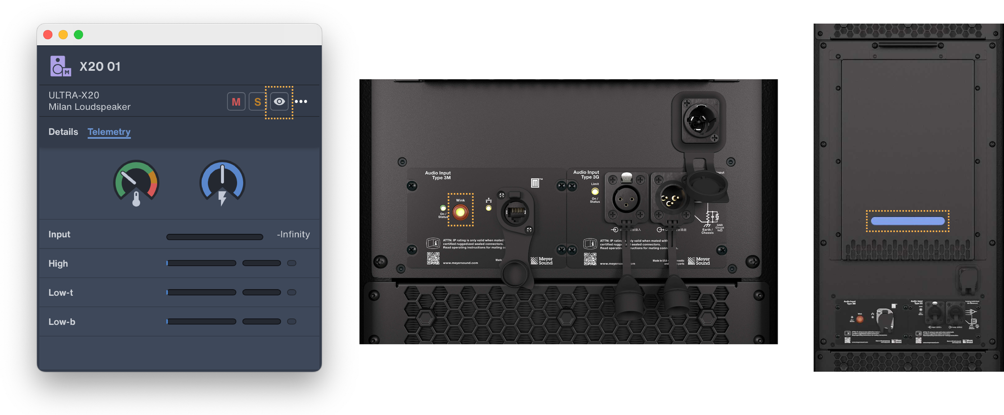
Wink Icon in Nebra, Wink Button/LED, and Blue LED Bar Highlighted
Wink/Activity LED Button
To activate the Wink function in Nebra software, double-click the icon that resembles an eye, highlighted in the figure above.
To activate the Wink function from the loudspeaker, press and hold the Wink button down while observing the Limit/On/Status LED, which turns red and then off. Release the Wink button when the Limit/On/Status LED turns off, activating the Wink function. The Wink LED turns yellow for 10 seconds. If the Wink button remains depressed, the Limit/On/Status LED will turn red again, and the Wink function will remain off.
To turn off the Wink function, wait 10 seconds for it to time out, or double-click the Wink icon in Nebra software. To turn off the Wink function from the loudspeaker, depress and hold the Wink button — the On/Status LED will turn red. Wait until the On/Status LED turns off, then release the Wink button.
Ethernet/Network Connectivity LED
The Ethernet/Network connectivity LED immediately to the left of the network connector is illuminated when a 100 bT link is established; otherwise, it is off.

Type 3M Milan Endpoint Module, On/Status LED, Wink Button/LED, Network Connection LED, and Network Connector
On/Status and Limiting Indication
When powered on, both of the On/Status LEDs blink many times and then turn solid green. During normal operation, the On/Status LEDs are solid green. If the On/Status LEDs blink red after the startup sequence, there is a potential issue to address. Connect the loudspeaker to a computer running Meyer Sound’s Nebra software to identify the issue. A list of the faults that can be reported is available in the Faults Reported by ULTRA-X80 On/Status LED table.
On/Status and Limit On/Status LEDs
Limiting activity is indicated when the Limit On/Status LED on the user panel turns from green to yellow, pulsing rapidly when the high-frequency channel limits and pulsing slowly when the low-frequency channels limit.
When limiting is engaged, the channel’s gain is reduced. The limiter protects the drivers and prevents signal peaks from causing excessive distortion in the amplifier, thereby preserving headroom and maintaining a smooth frequency response at high levels. When source levels return to normal, below the limiter’s threshold, the LED turns green, and limiting ceases.
The loudspeaker performs within its acoustical specifications at normal temperatures when the Limit On/Status LED is green or when limiting is not continuous. During continuous limiting, the loudspeaker is nearing its operational limits, resulting in the following effects:
Increases to the input level have no effect
Distortion increases due to clipping and nonlinear driver operation
The drivers are subjected to excessive heat and excursion, which compromises their life span and may eventually damage them
Caution
The Limit On/Status LED indicates when a safe, optimum level is exceeded. If an ULTRA-X80 loudspeaker begins to limit before reaching the desired acoustic output, consider adding more loudspeakers to the system.
TruPower Limiting
The ULTRA-X80 employs Meyer Sound’s advanced TruPower® limiting. Conventional limiters assume a constant driver impedance and set the limiting threshold by measuring voltage alone. This method is inaccurate because driver impedances change as frequency content in the source material changes and as thermal values for the loudspeaker’s voice coil and magnet vary. Consequently, conventional limiters often begin limiting prematurely, which reduces system headroom and dynamic range.
In contrast, TruPower limiting anticipates varying driver impedances by measuring both current and voltage to compute the actual power dissipation in the voice coil. This approach improves performance, both before and during limiting, by allowing the driver to produce the maximum SPL across its entire frequency range while also retaining signal peaks. TruPower limiting also eliminates power compression at high levels over lengthy periods, which helps regulate voice coil temperatures, thereby extending the life of the driver.
Amplifier Cooling System
ULTRA-X80 loudspeakers employ forced-air cooling to prevent overheating. Three variable-speed fans pull air through the inlet grille located below the user panel, as shown in the figure below. Behind the inlet grille, a filter captures particulates.
Caution
To prevent the ULTRA-X80 loudspeakers from overheating, allow at least 15 cm (6 inches) of space with unobstructed airflow behind enclosures for proper ventilation.
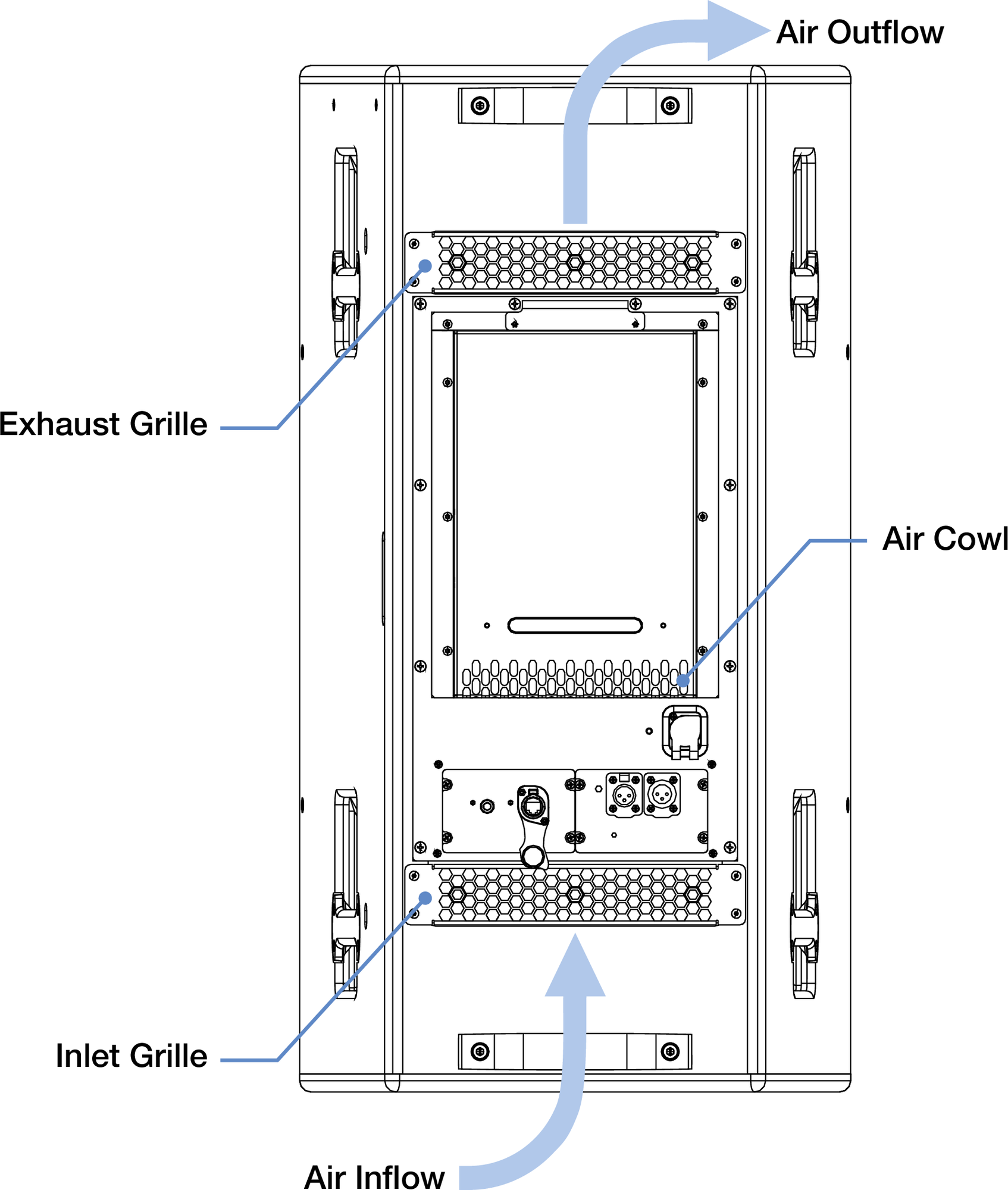
ULTRA-X80 Loudspeaker Air Flow Diagram
When the rear of an ULTRA-X80 loudspeaker is located near a large surface, always maintain the minimum clearance for proper ventilation. For example, when the loudspeaker is mounted to a ceiling and needs to face almost directly down, attach the loudspeaker to the attachment point of the u-bracket illustrated below. This allows for the maximum distance between the amplifier air inlet/exhaust and the ceiling, maximizing airflow.
Ceiling Mounted MUB-T1 Mounted to an ULTRA-X80 Loudspeaker, Maximum Clearance Distance
Caution
Regularly inspect the filter behind the air inlet grille located below the user panel. If a significant amount of particulate has accumulated on the filter, remove the inlet grille and then the filter. Vacuum the filter, and if necessary, rinse the filter with water until the particulate is removed. Allow the filter to dry completely, then reassemble.
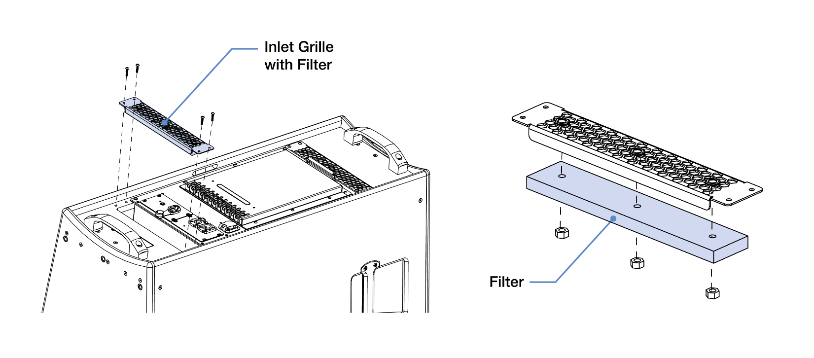
Inlet Grille and Filter Removed
Tip
When ULTRA-X80 loudspeakers are connected to a network, Meyer Sound’s Nebra software displays telemetry metrics, including the fan status and operating temperature.
Horn Rotation
The ULTRA-X80 horns can be rotated to provide the desired dispersion independent of cabinet orientation. The horn has two correct orientations illustrated below, Meyer logo at the top, or to the left relative to the vertical cabinet orientation.
When looking at the front of the loudspeaker, there are few prompts beyond the logo on the grille to determine the cabinet orientation. The cups behind the handle grasp bars, the serial number plate, and the orientation of the user panel on the rear aid in the determination of the top/bottom of the loudspeaker, illustrated below on the right.
Note
Exchanging the horn of an ULTRA-X80 with an ULTRA-X82 horn, or vice versa, is not supported.
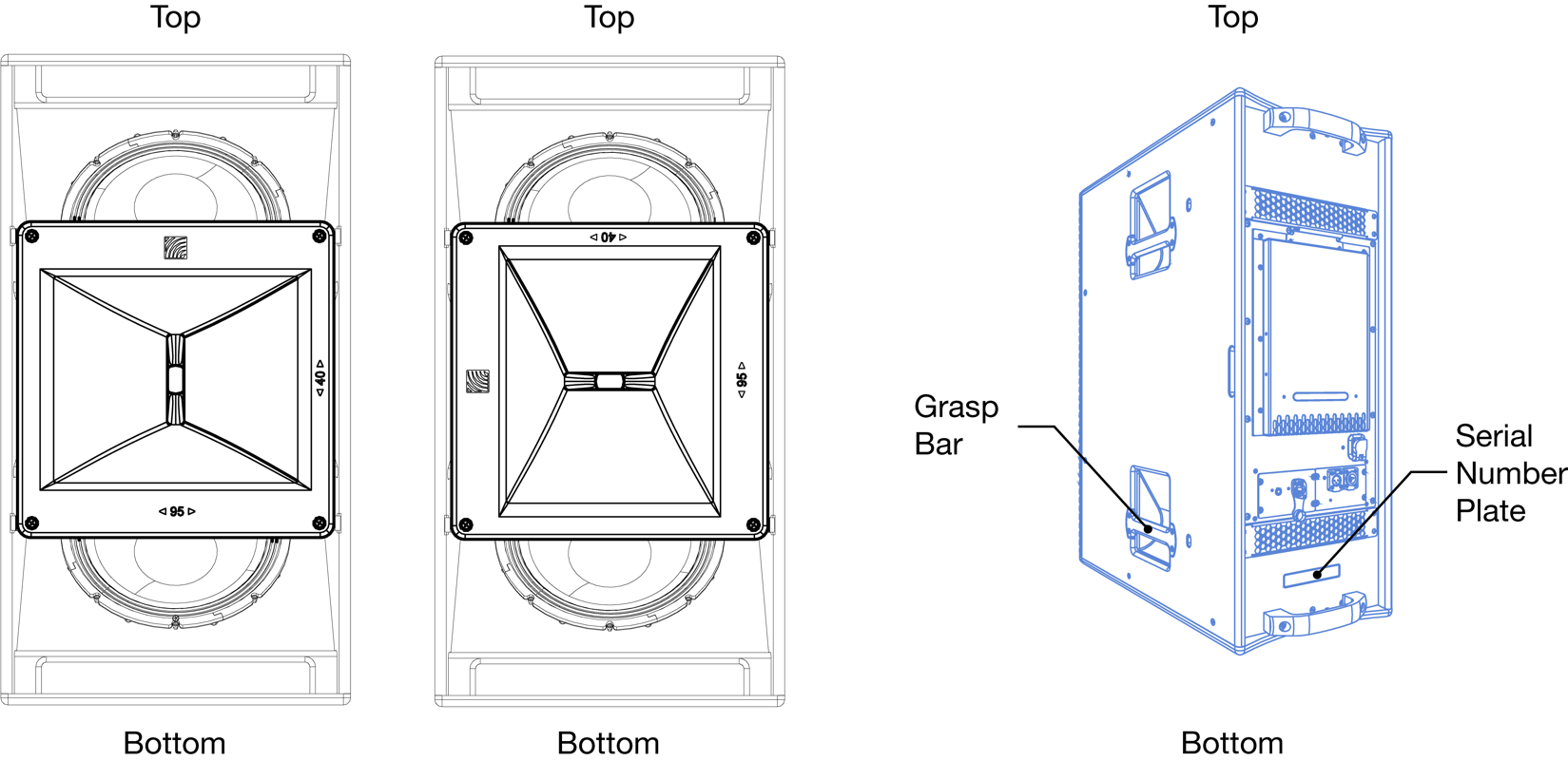
Correct ULTRA-X80 Horn Orientations (left, middle) and Top/Bottom References (right)
Horn Rotation Instructions
Remove the six screws (PN 101.675) that secure the grille, illustrated below. Grasp the sides of the grille and lift to remove. Set the grille and mounting screws aside for later re-installation.
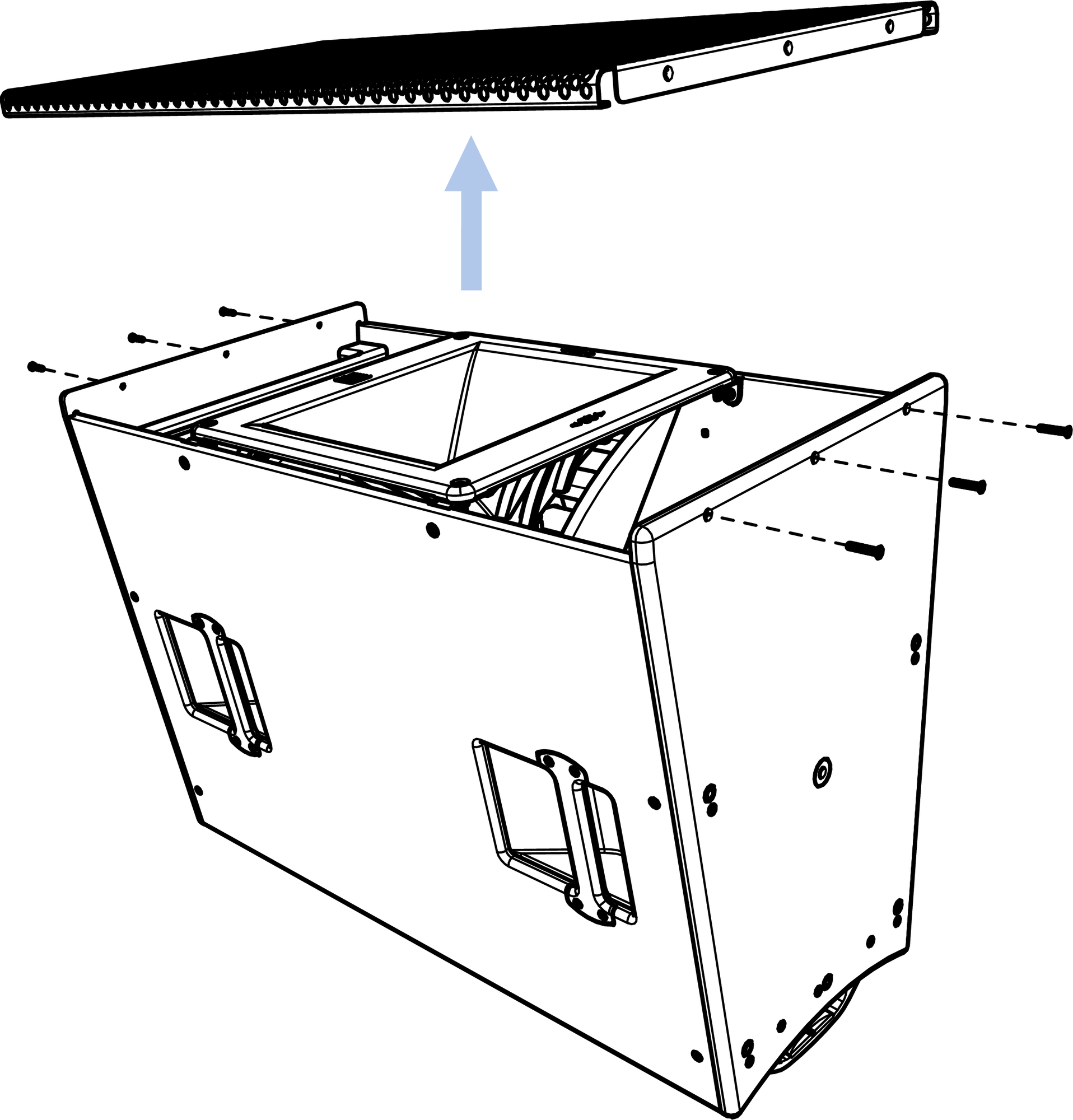
Remove the Six Screws from the Top and Bottom of the Loudspeaker, Lift the Grille to Remove
Remove the four screws (PN 101.620) securing the horn, lift the horn approximately 15 cm (6 in), and rotate it 90-degrees and lower it.
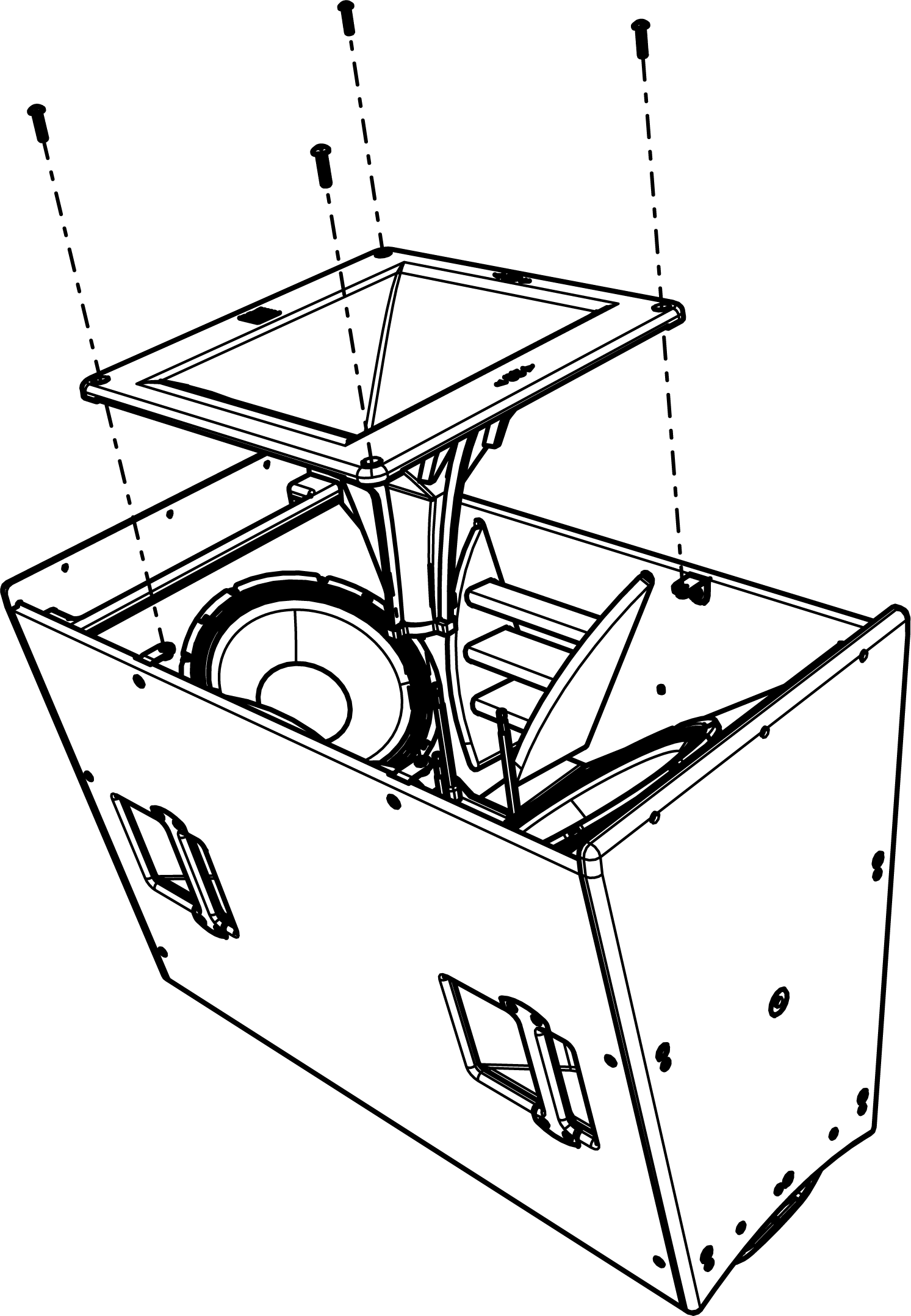
Remove the Four Screws Securing the Horn
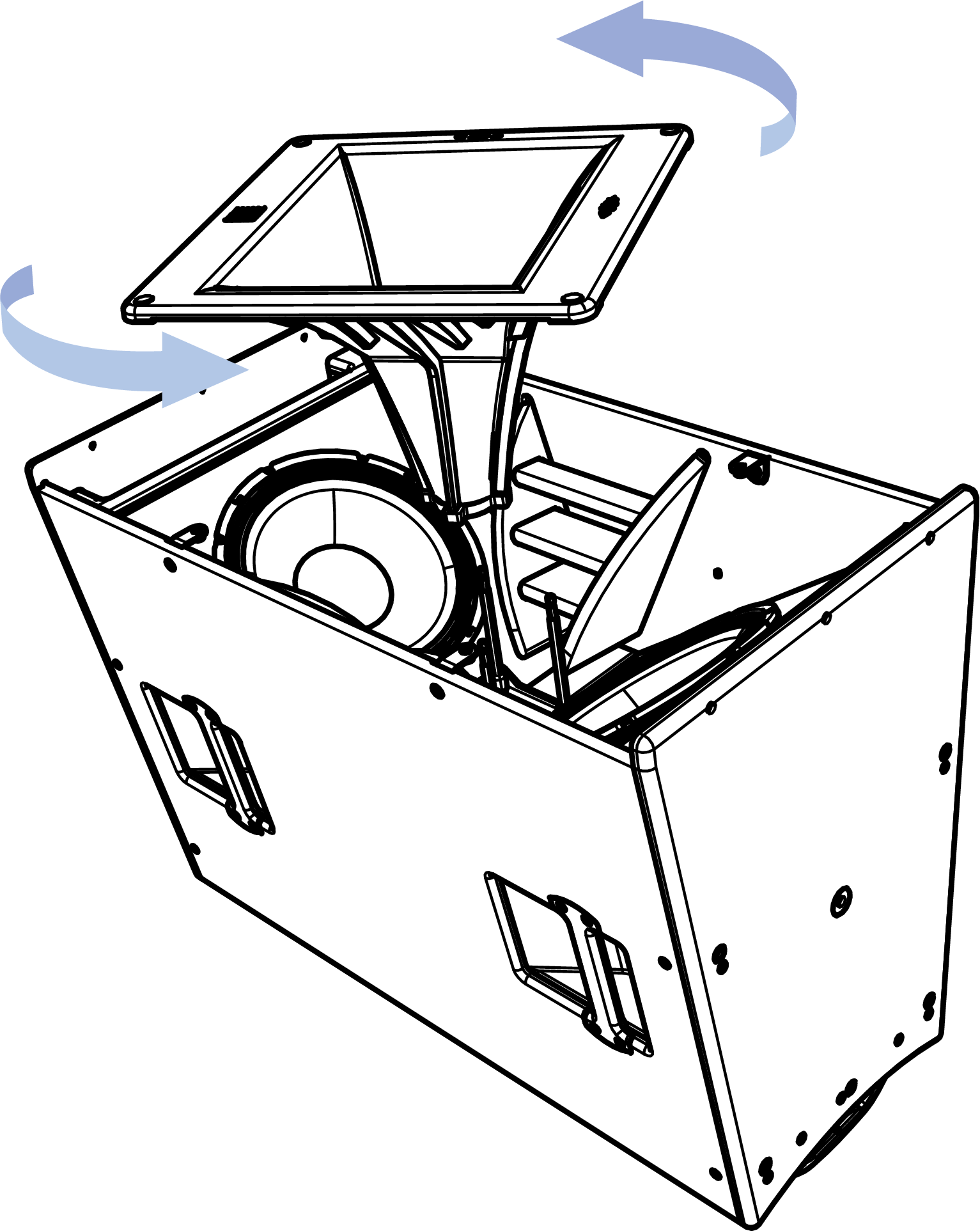
Rotate the Horn and Reassemble
Replace the four screws removed in Step 2 that secure the horn. Tighten these to 2.7 N-m (24 in-lb) of torque.
Replace the grille and secure it with the six screws removed in Step 1. Meyer Sound recommends applying thread locker (medium strength, PN 640.096) to the leading three threads of the screws before replacing them. Tighten the grille screws to 1.4 N-m (12 in-lb) of torque.
Environmental Protection
The ULTRA-X80 is available in Standard (STD) or Outdoor Temporary (OT) versions. The Standard version is suitable for applications that are exclusively indoors. The Outdoor Temporary version protects the loudspeaker from occasional exposure to moisture and/or particulate and is suitable for use outdoors in temporary applications like a weekend outdoor music festival. Additional protection is needed when these loudspeakers are permanently mounted in locations that expose them to the natural environment, for example, rain, fog, condensation, high levels of UV light, chlorine or other water-treatment chemicals, wind-blown sand, dirt, particulate, or water, etc.
Adding Low-Frequency Models
ULTRA-X80 loudspeakers are designed to be deployed with Meyer Sound self-powered LFC models listed in the table below. These low-frequency models extend the system response appreciably, increasing the overall acoustic power of the system in the lowest frequencies.
The ratio of low-frequency models to ULTRA-X80 loudspeakers generally depends on the following variables:
Low-Frequency loudspeaker model
System configuration
Frequency content of source material
Headroom required for low frequencies
For the various applications listed in the columns of the table below, ratios of low-frequency models to one ULTRA-X80 loudspeaker are provided as guidance to achieve the desired amount of low-frequency gain.
Note
The column in the table above labeled Pop C Minus A refers to a 6 dB sound level difference between the A-weighted and C-weighted sound levels.
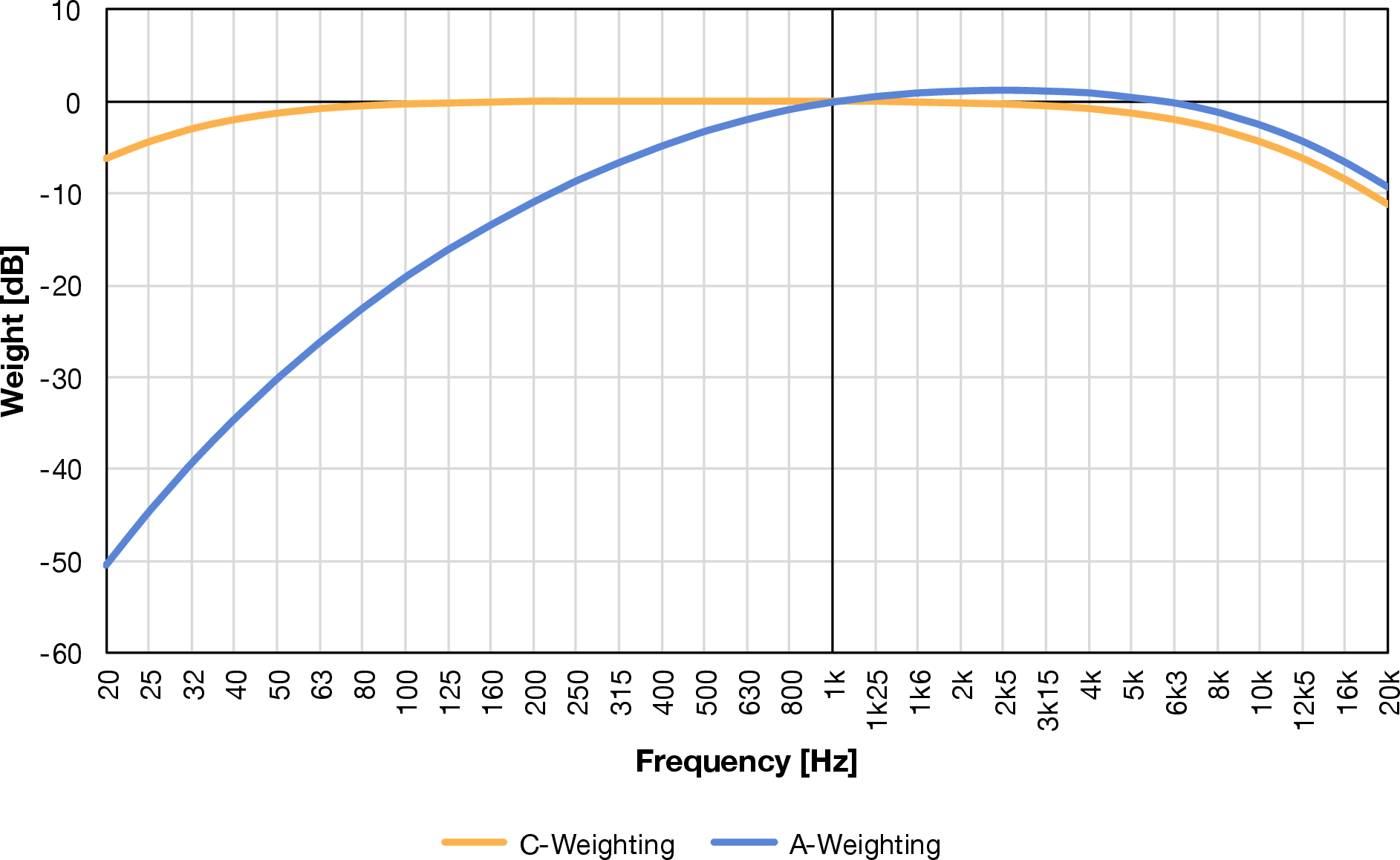
IEC 61672 Weighting Curves
Adding Low-Frequency Models by Daisy-Chaining Signal
Full-range signals can be connected directly to Meyer Sound self-powered loudspeakers because the loudspeakers have built-in active crossovers. Low-frequency models can be added to an ULTRA-X80 system by simply daisy-chaining the analog signal. Connect the source signal to one of the Inputs, then connect the Loop output to the next loudspeaker, and so forth.
When ULTRA-X80 loudspeakers are coplanar to the low-frequency models, or they are very close together, about one to two meters (three to six feet), the phase response is aligned enough through the acoustic crossover to be constructive, and the result will be a relatively flat frequency response. However, the response will have a gain increase in the 60–200 Hz range, where the loudspeaker responses overlap.
Caution
Make sure the source signal is sufficient to drive the total load impedance of the daisy-chained loudspeakers (see Calculating Analog Input Load Impedance).
Note
If the low-frequency model indicates limiting before reaching the desired sound level, consider adding additional units to meet the desired sound level without exposing the drivers to excessive heat and excursion.
Adding Low-Frequency Models Using a Processor
When independent control of the signals reproduced by various loudspeaker models is needed or desired, a Galileo GALAXY signal processor is recommended. The same, full-range source signal can be routed to both an ULTRA-X80 and a low-frequency model, which can be modified with filters, gain, delay, and polarity settings in addition to the built-in signal processing. To determine the processor settings, dual-channel FFT measurements provide the most actionable data.
Note
One or more (up to 20) Meyer Sound loudspeakers can be connected to a single Galileo GALAXY output by daisy-chaining the signal as described above.
Tip
Meyer Sound’s System Design and Prediction Tool, MAPP 3D, can be used to accurately predict the appropriate loudspeaker deployment for a system, including coverage data, system delay and equalization settings, rigging information, and detailed design illustrations.
QuickFly Rigging
The ULTRA-X80 models are compatible with Meyer Sound’s QuickFly system, a comprehensive collection of custom-designed rigging, flying, and mounting options.
Important Safety Considerations!
When installing Meyer Sound loudspeakers, the following precautions should always be observed:
All Meyer Sound products must be used in accordance with local, state, federal, and industry regulations. It is the owner’s and user’s responsibility to evaluate the reliability of any rigging method for their application. Rigging should only be carried out by experienced professionals.
Use mounting and rigging hardware that has been rated to meet or exceed the weight being hung. Make sure to attach mounting hardware to the building's structural components (studs or joists) and not just to the wall surface. Verify that the building's structure and the anchors used for the installation will safely support the total weight of the mounted loudspeakers.
Use mounting hardware appropriate for the surface where the loudspeaker will be installed.
Make sure the fasteners are tightened securely. Meyer Sound recommends using medium-strength thread locker on fastener threads.
Inspect mounting and rigging hardware regularly. Immediately replace any worn, bent, or damaged components.
Rigging Points
The top and bottom of the ULTRA-X80 cabinets include 12 high-strength, corrosion-resistant stainless steel rigging points that provide threaded holes for connection to QuickFly rigging and third-party mounting options, as shown in the figure below. The five perimeter rigging points have a thread depth of 13.5 mm (0.53 in), while the centrally located rigging point threads are 23 mm (0.90 in) deep. Each rigging point is rated for at least a 5:1 safety factor for the weight of one ULTRA-X80 loudspeaker.
Caution
The fasteners included with rigging accessory kits are the appropriate length to engage the threads sufficiently. For connection to third-party assemblies not provided by Meyer Sound, it is the user’s responsibility to ensure the fastening hardware is long enough to engage all the threads but not bottom out when the fastener is properly tightened and is sufficiently rated for the application.
The maximum torque for hardware threaded into the rigging attachment points located on the top and bottom of ULTRA-X80 loudspeakers is 13.3 N-m (120 in-lb).
Top and Bottom Rigging Point Locations, Twelve Total
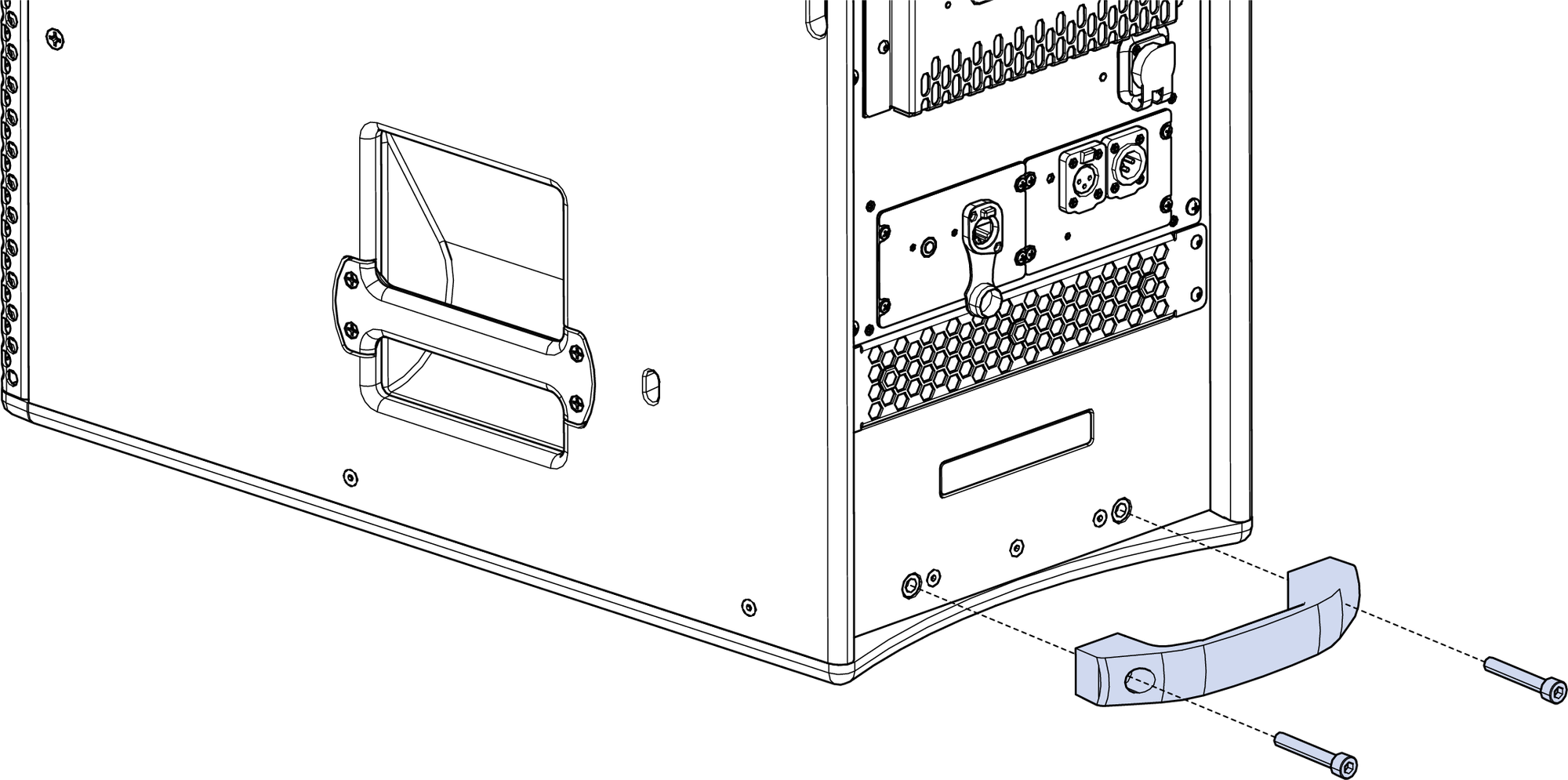
Rear Handles
The two handles located on the rear of the cabinet have two functions: an additional grasping point when moving the loudspeaker and, unusual for Meyer Sound loudspeakers, a secondary/safety rigging connection. These handles have been rated for both perpendicular and parallel loading with at least a 5:1 safety factor for a single cabinet.
If desired, the rear handles can be removed for cosmetic reasons. They can also be removed and sufficiently rated and properly sized eye bolts or hoist rings threaded into the handle attachment points if needed for specific rigging methods. These attachment points are M8 x 1.25mm pitch with 13.5 mm of thread depth and have a maximum torque of 13.3 N-m (120 in-lb).
Side Handles
The handles located on the sides of the ULTRA-X80 cabinets are only intended for manual lifting and moving of the loudspeaker without mechanical assistance.
Caution
Do not attach anything to the four handles located on the sides of the cabinet. They are not safety-rated.
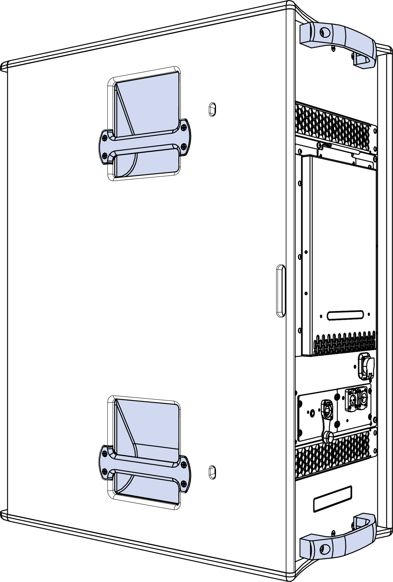
ULTRA-X80 Side and Rear Handles Highlighted
Mounting Information
When mounting ULTRA-X80 loudspeakers, it is generally required to employ two loudspeaker attachment points to the structure it’s being suspended from, a primary and a secondary/safety mounting point, each sufficient to carry the entire load with adequate margin. In addition to user-provided eyebolts or hoist rings, the rear handles can serve as this secondary or safety mounting point.
Caution
Because these handles are metallic, if the safety point hardware is also metallic, a protective material is required to prevent wear of either or both the rear handle and the safety point hardware, e.g., flexible plastic tubing.
Accessories
The available ULTRA-X80 rigging accessories listed in the table below are sold separately with the related ULTRA-X80 loudspeaker information.
Model | Part Number | Weight | Features |
|---|---|---|---|
ULTRA-X80 | see Price List | 62.6 kg (138 lb) | 12 total mounting points, six on top, six on bottom Rear handles are rated for secondary/safety connection |
MY-T1 | 40.330.039.01 | 14.5 kg (32 lb) | Yoke |
MUB-T1 | 40.330.055.01 | 6.8 kg (15 lb) | U-Bracket |
MY-T1 Yoke
The MY-T1 Yoke suspends a single ULTRA-X80 loudspeaker, allowing both pan and tilt adjustment. The yoke attaches to the top of the loudspeaker in four locations with either hand screws for temporary deployment or bolts that minimize the visual aesthetic for installations, as shown in the figure below. To secure the rotation points of the yoke halves, the kit includes both machine handles for temporary deployment and nuts that minimize the visual aesthetic for installations. A rated hanging clamp or fasteners and secondary/safety attachment hardware (not included) are required to suspend the MY-T1 Yoke. This accessory is available in custom colors. The fastening hardware is always black.

MY-T1 Yoke, Permanent (left) and Temporary (right) Fastener Options, Both Included
Caution
Never suspend anything other than one ULTRA-X80 loudspeaker with a MY-T1 Yoke. This yoke is rated to suspend a single ULTRA-X80 loudspeaker with a 5:1 safety factor.
The ULTRA-X80 and ULTRA-X82 loudspeakers weigh 62.6 kg (138 lb) and the MY-T1 Yoke weighs 14.5 kg (32 lb), and the combined weight is 77.1 kg (170 lb). The hardware and/or fasteners that are used to secure the MY-T1 to the building structure must be adequately rated to carry the combined weight with additional safety margin, usually a 5:1 safety factor.
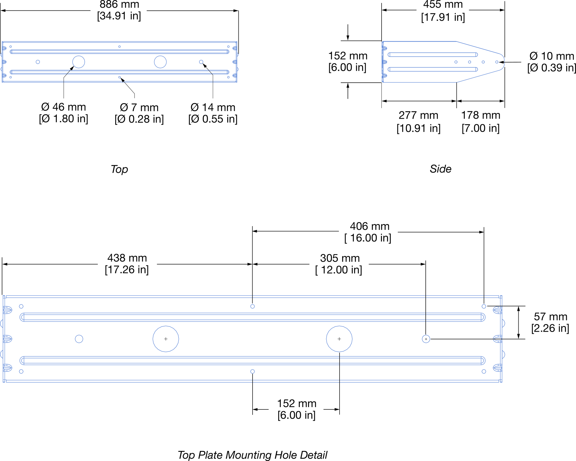
The top plate of this yoke accommodates hanging clamps with standard 1/2-inch or 12 mm diameter hardware connected to the center mounting point. See the illustration below for dimensional details.
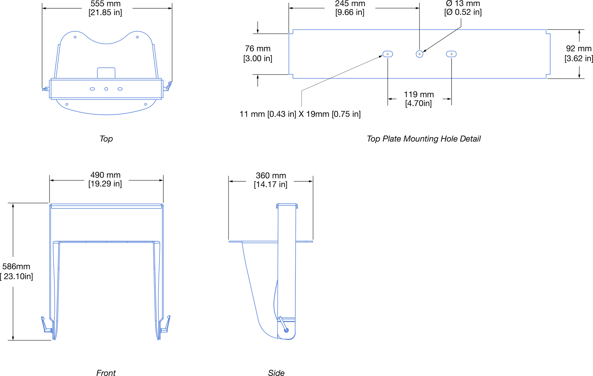
MY-T1 Yoke Dimensions
MY-T1 Yoke Rigging Points
The MY-T1 Yoke is fastened to four of the rigging points located on the top and bottom of an ULTRA-X80 loudspeaker.
ULTRA-X80 Loudspeaker, Top/Bottom MY-T1 Yoke Mounting Locations Highlighted
Mounting Options
When mounting an ULTRA-X80 loudspeaker with a MY-T1 Yoke, two structural connections are generally required: a primary and a secondary/safety mounting point, each sufficient to carry the entire load with at least a 5:1 safety factor. The yoke provides the primary connection point. There are two options for the secondary connection:
Uncommon for Meyer Sound loudspeakers, the rear handles of ULTRA-X80 loudspeakers are rated at 5:1 safety factor for a single cabinet.
Make a connection between one of the rear handles and the structure it is being suspended from, usually with wire rope. If the secondary/safety point connection hardware is metallic, a protective material is required to prevent wear of the loudspeaker’s metal handle, e.g., flexible plastic tubing.
Remove a rear handle and thread two sufficiently rated and properly sized eye bolts or hoist rings into the handle mounting points (M8 x 1.25 pitch, 13.5 mm deep). Make connections between these points and the building's structural attachment point(s).
ULTRA-X80 Rear Handle Removed
MY-T1 Kit
Meyer Sound Part Number | Image | Qty | Description |
|---|---|---|---|
45.330.042.01 | 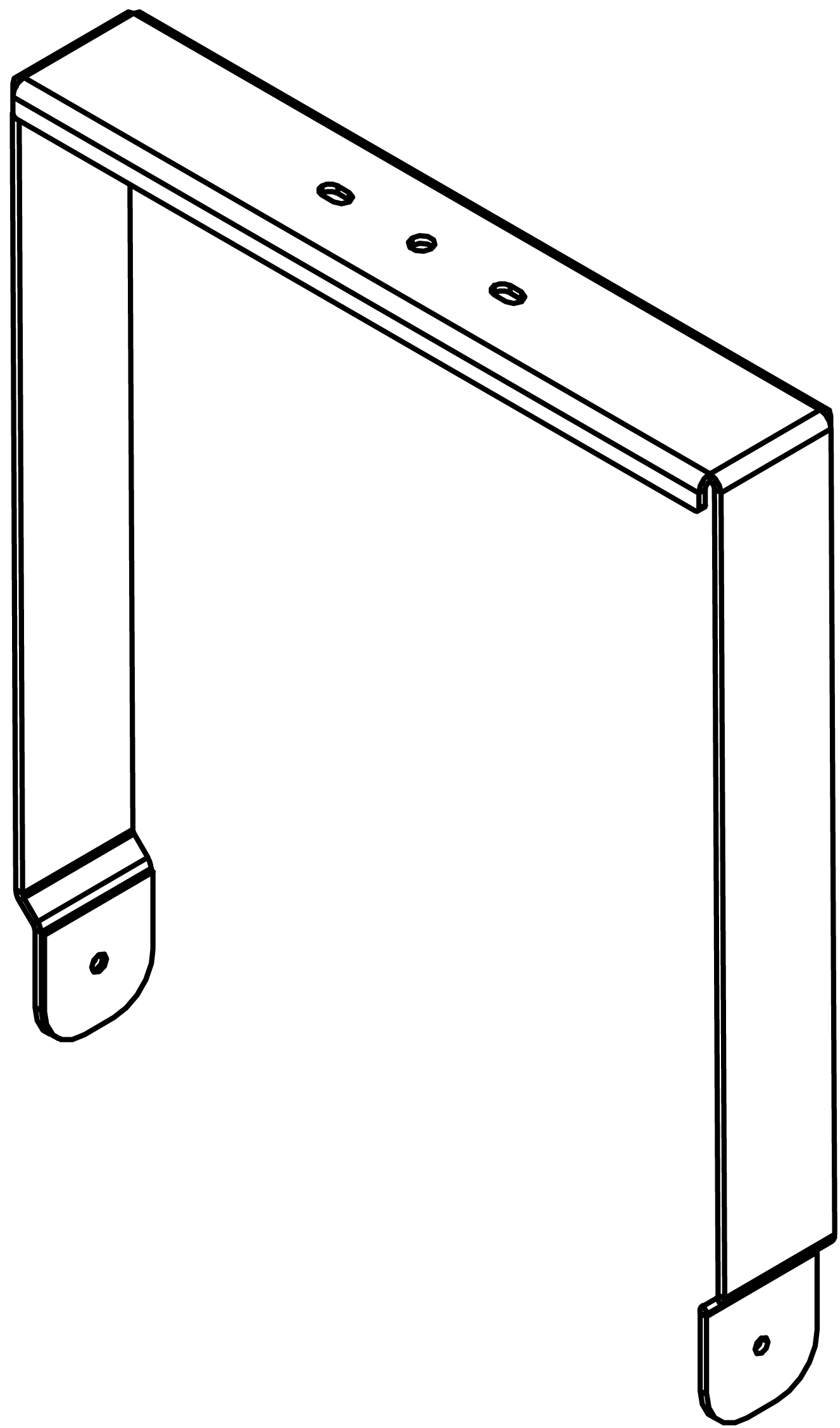 | 1 | MY-T1 TOP PLATE WITH GASKET & LABEL ASSY |
64.330.044.01 | 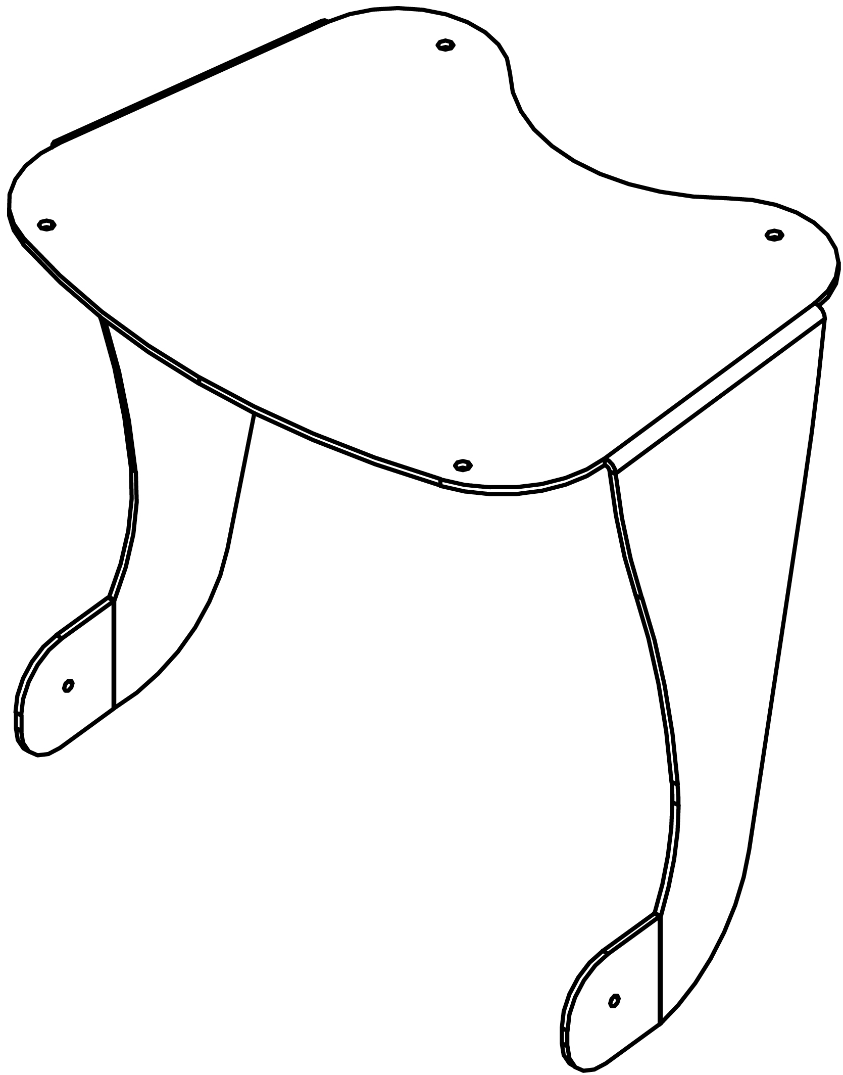 | 1 | YOKE BOTTOM PLATE |
101.720 | 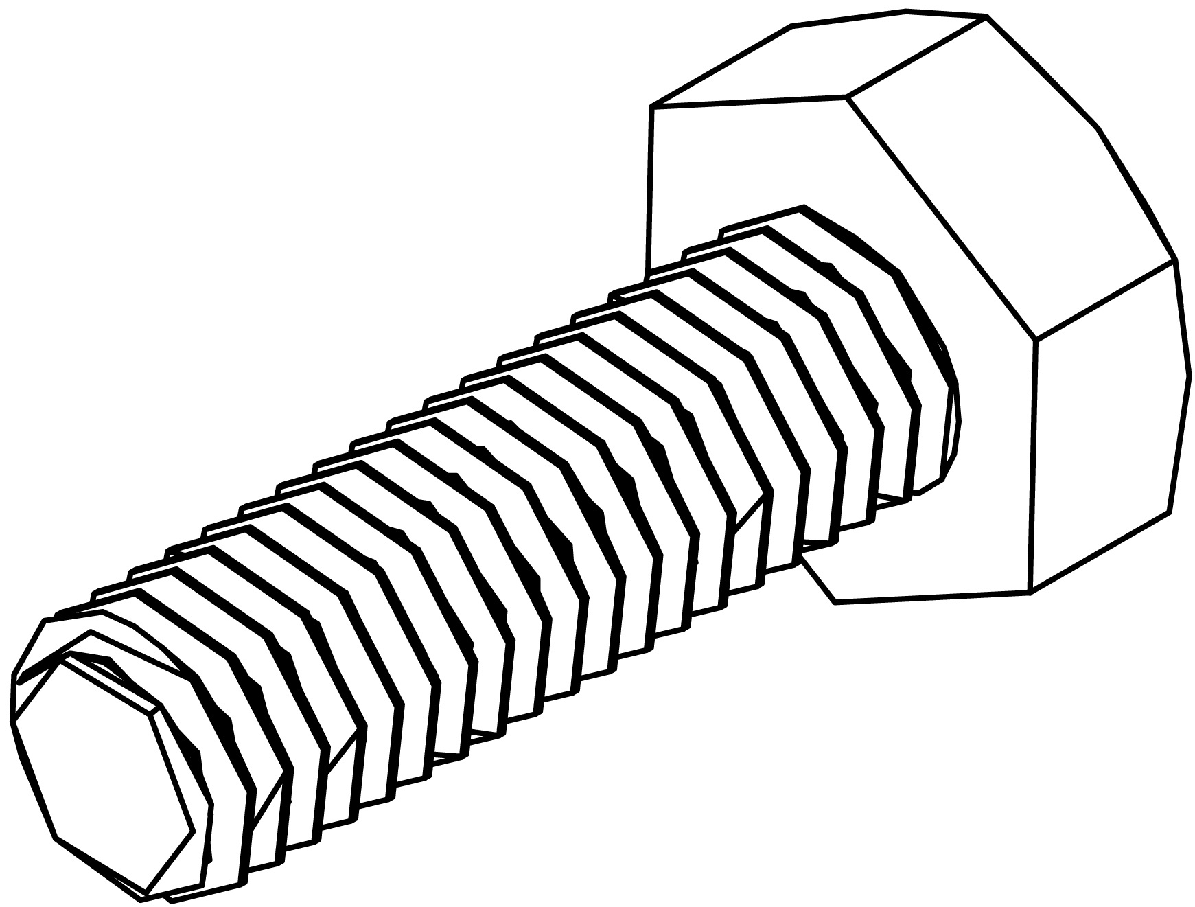 | 2 | SCREW, HEX HEAD, M8 1.25 X 20 MM, STAINLESS, BLACK OXIDE |
640.098 | -- | 1 | ADHESIVE LOCTITE THREADLOCKER 263, 0.5ml |
124.066 | 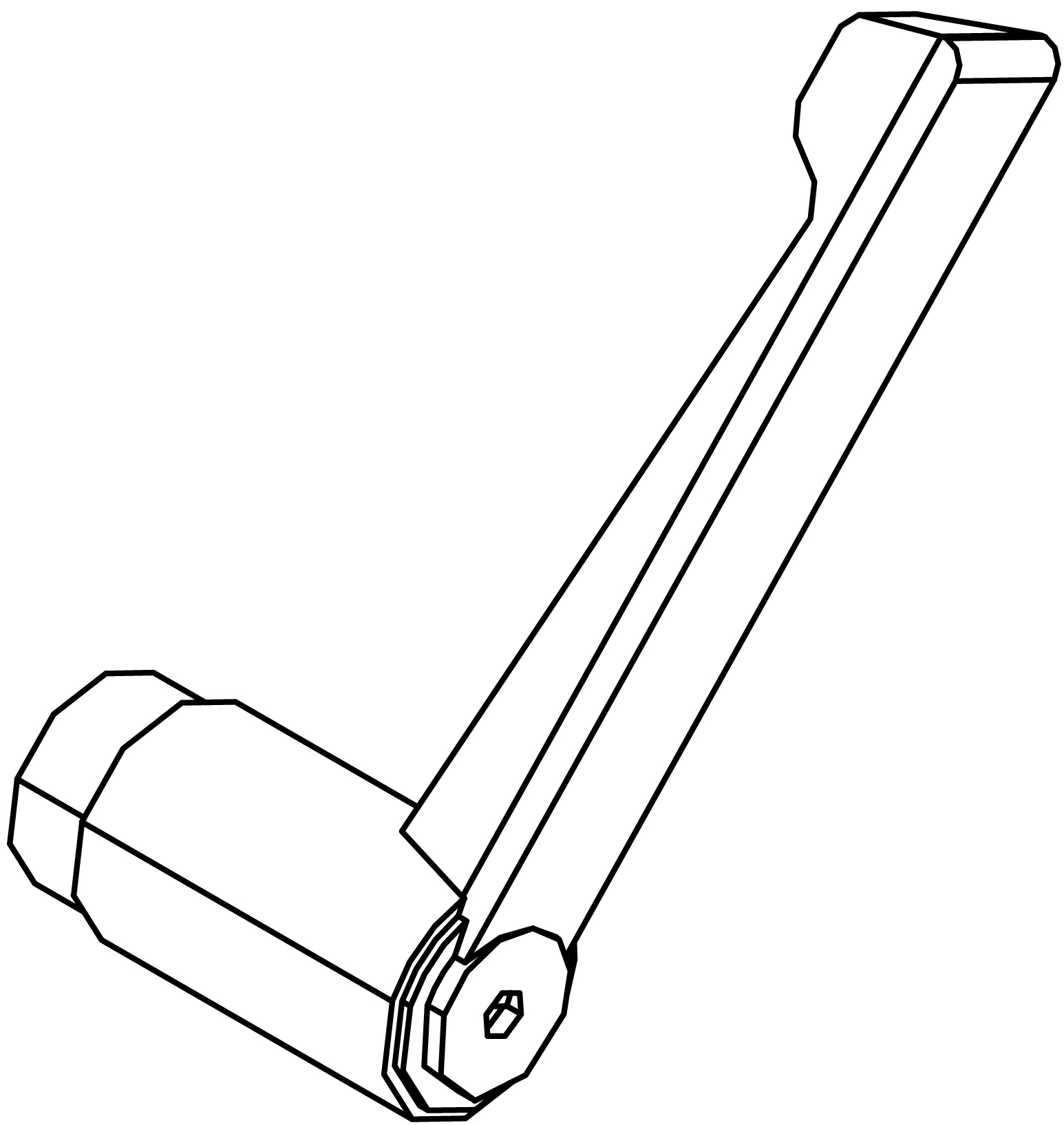 | 2 | MACHINE HANDLE M8 DIE CAST ZINC BLACK |
113.532 | 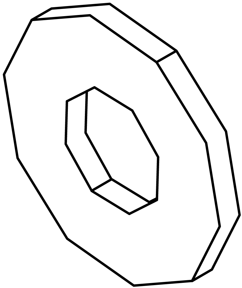 | 2 | WASHER, FLAT, 8.4 MM ID, 24 MM OD, 1.8 MM THICK, STAINLESS, BLACK |
109.551 | 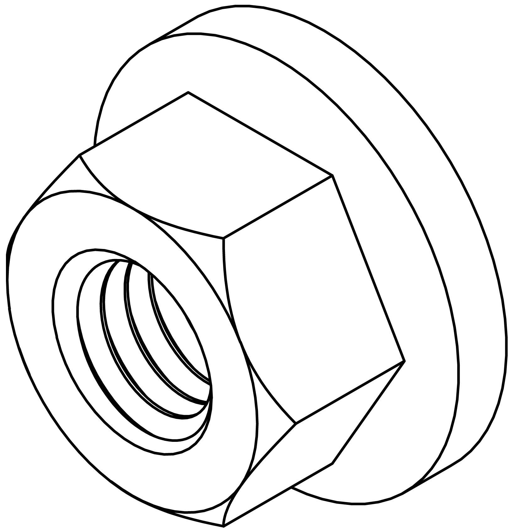 | 2 | NUT, SMOOTH FLANGE M8-1.25, STAINLESS, BLACK OXIDE |
45.287.061.01 | 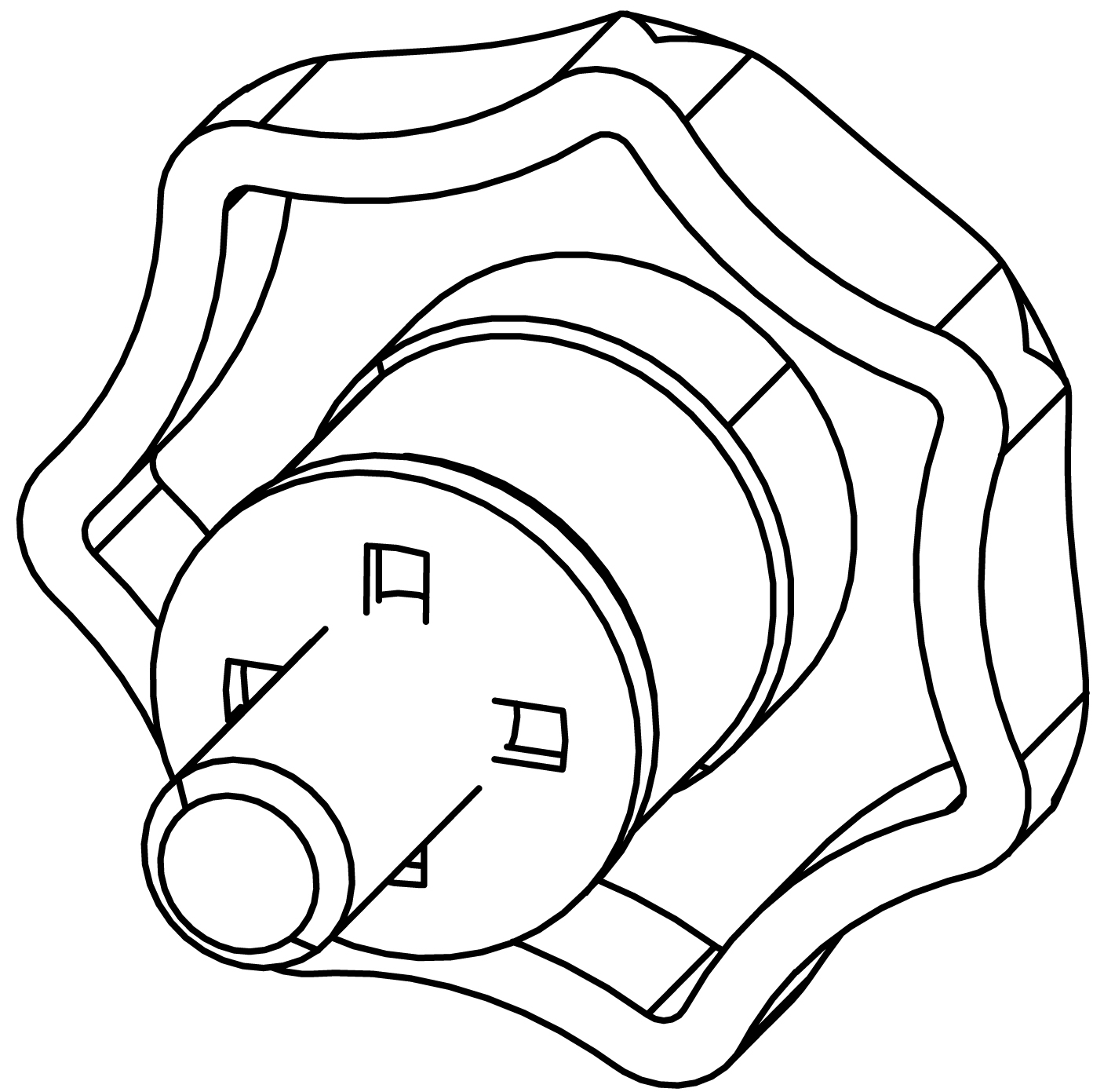 | 4 | KNOB & WASHER, M8 x 16.5mm, BLACK, STAINLESS ASSY 124.149 Knob 119.087 Retaining Washer |
45.287.461.01 | 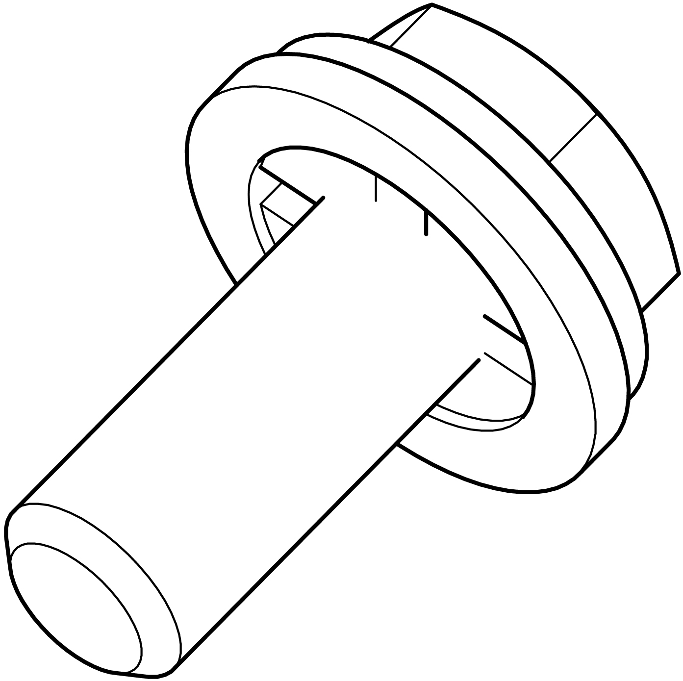 | 4 | SCREW W/WSHR, HEXHD, M8 x 17 MM, STAINLESS, BLACK 119.087 Retaining Washer 113.530 Flat Washer 101.720 Screw |
05.330.039.01 | -- | 1 | MY-T1 YOKE ASSEMBLY GUIDE |
40.010.475.01 | -- | 1 | RIGGING DOCS W/SERIAL NUMBER SHIPPING KIT |
MY-T1 Yoke Assembly Instructions
After unpackaging the MY-T1 Yoke Kit and confirming the contents match the parts and quantities listed in the table above, follow these steps to assemble and connect an MY-T1 Yoke to an ULTRA-X80 loudspeaker:
Please review these assembly steps before starting. They are less intuitive than you may imagine.
Position the two yoke halves on a flat surface and orient them exactly as illustrated in the figure below.
Note
The yoke half illustrated on the left is symmetrical, either side can face up. The yoke half on the right is not symmetrical and needs to be oriented as it is illustrated below.
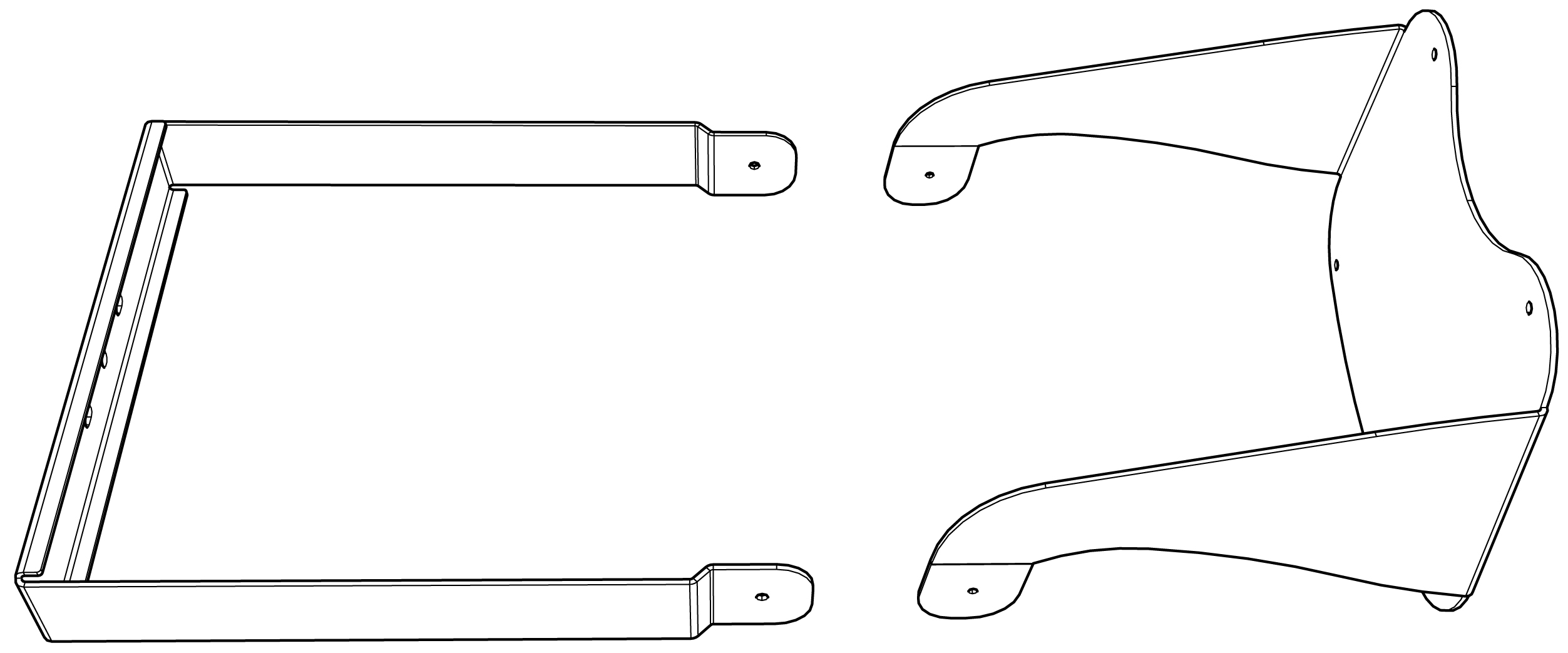
Two Halves of the MY-T1 Yoke Correctly Oriented for Assembly
As illustrated on the right in the figure below, from the inside of the arms, thread the two hex-head screws (PN 101.720) into the threaded holes, stopping before the threaded end protrudes from the other side of the arm.
Note
The yoke half illustrated on the left does not have threaded holes.
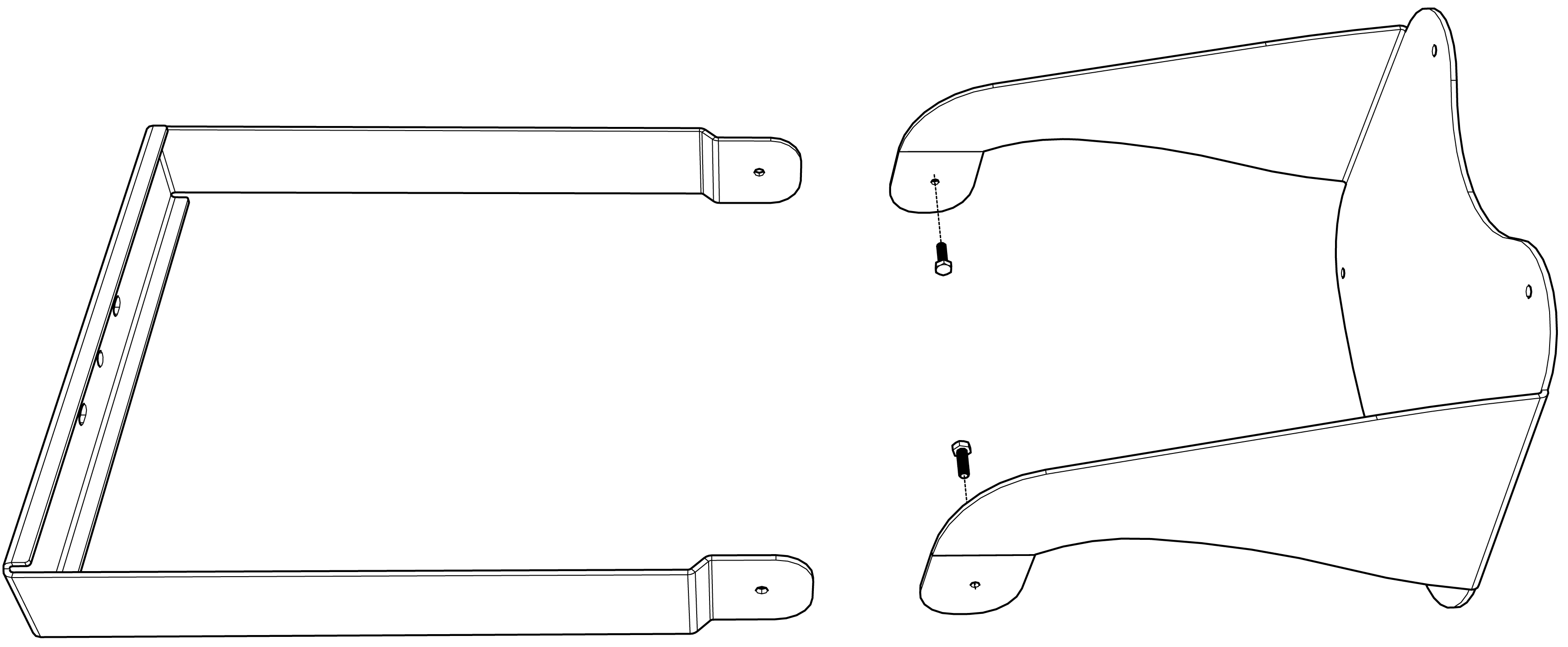
Start Hex-Head Screws in Threaded Holes of the Yoke Arms of the Right-Hand Yoke Half
Apply 3 drops of thread locker (PN 640.098) to the threads of both screws, closest to the head of the screw.
Note
The thread locker helps retain the screw after assembly, preventing the screw from backing out when the tensioning hardware is loosened.
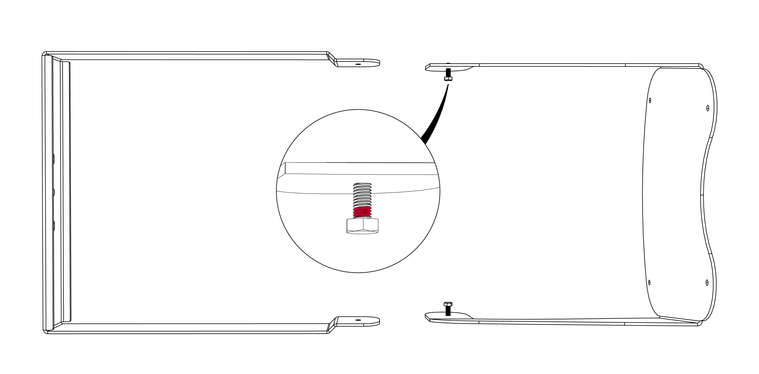
Apply Thread Locker to the Threads Nearest Screw Heads
Move the left half of the yoke toward the right half until the holes at the ends of the arms are aligned, as shown in the figure below.
Note
The halves of the yoke are correctly aligned when the arms of the left half are outside the arms of the right half, as shown in the figure below.
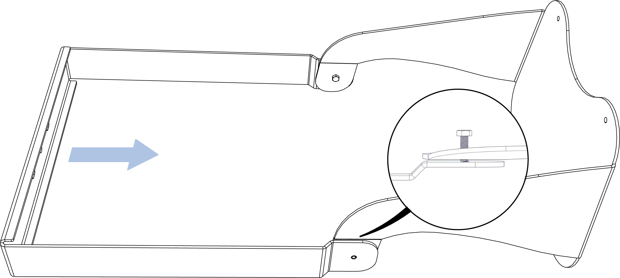
Slide Halves Together Aligning Holes at End of Arms
Continue to tighten both screws to 13.3 N-m (120 in-lb) of torque.
Continue Tightening Screws
Caution
Once assembled, always tighten the tensioning hardware and handle the yoke by grasping both halves as they present a hand/finger pinch point.
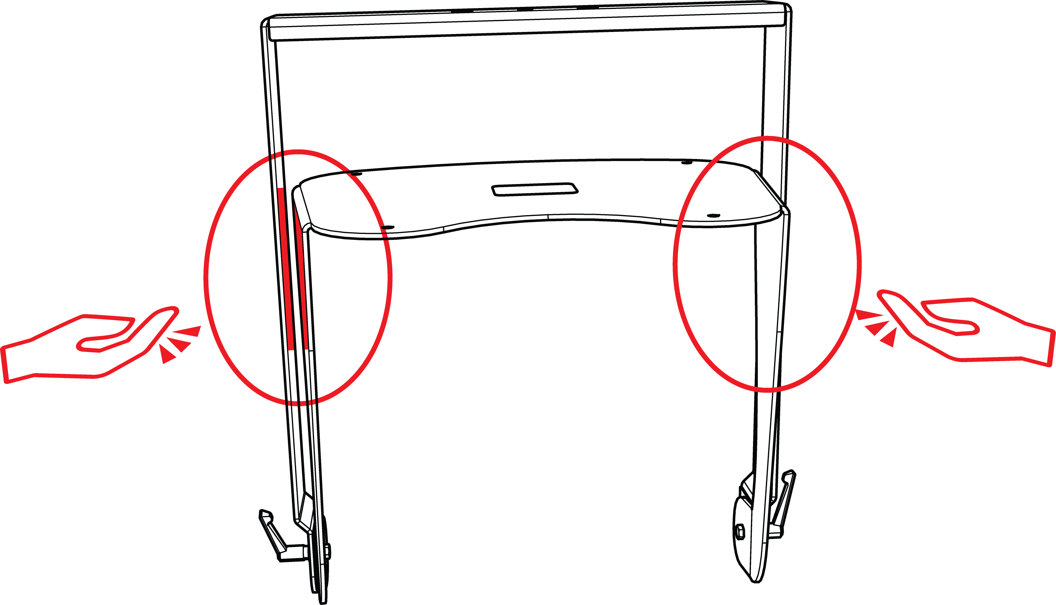
Hand Pinch Points Between Yoke Halves
Caution
Always tighten the tensioning hardware and handle the yoke by grasping both halves. If the yoke is grasped by only one of the halves and the tensioning hardware is loose, there is a risk of injury if one of the halves rapidly realigns to gravity and impacts the lower extremities of the person handling the yoke.
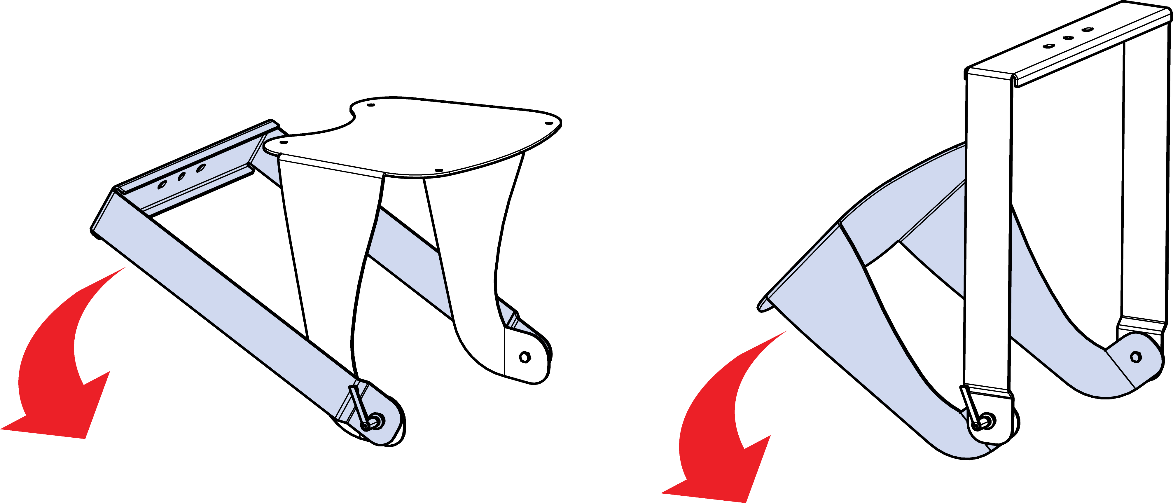
Loose Tensioning Hardware, Unrestrained Yoke Half Rapidly Orients to Gravity
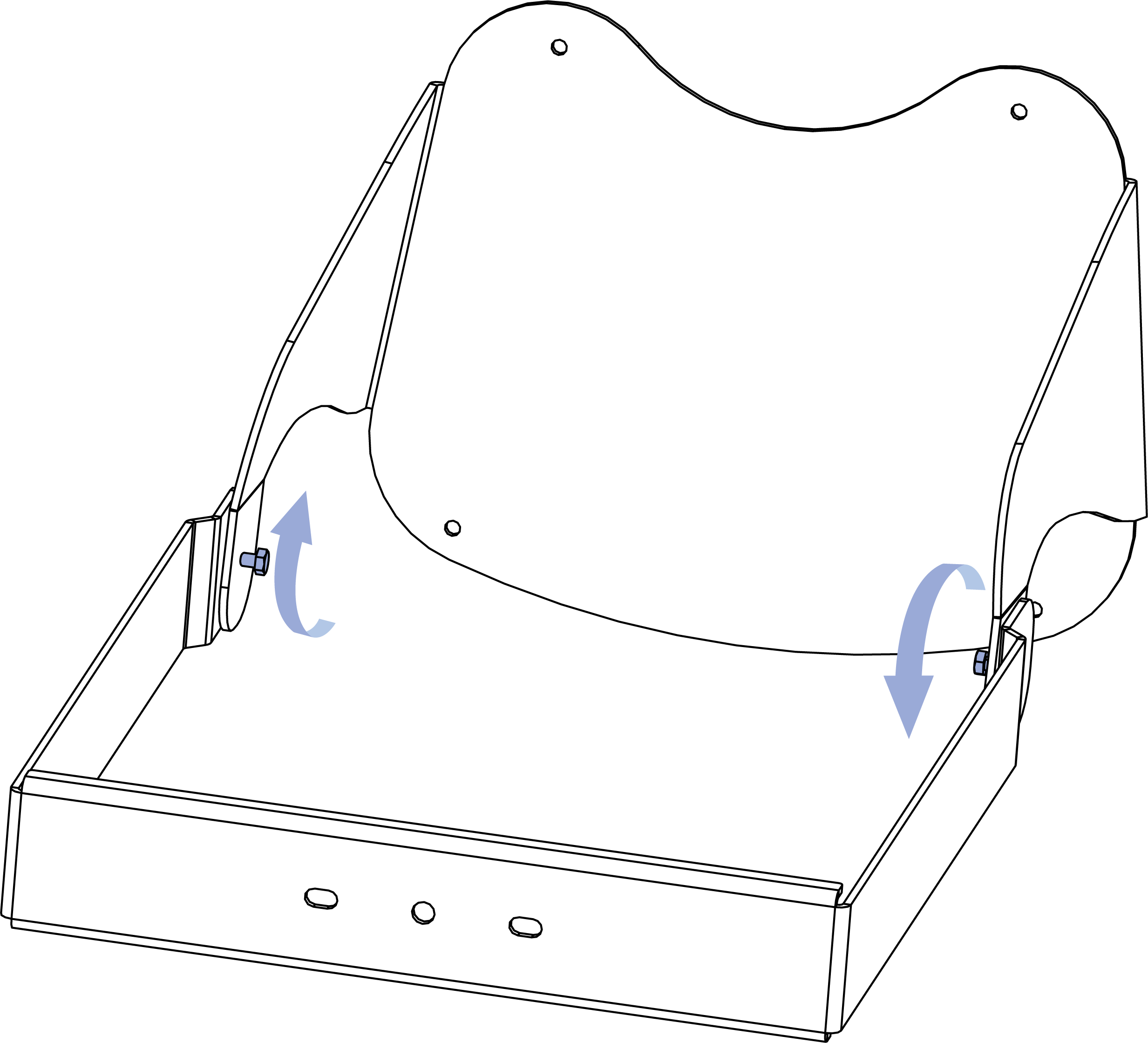
Perform these tasks in order, as illustrated in the figure below:
Thread one of the tensioning hardware options onto both screws using either the machine handle or nut:
Machine handle: Slide a washer (PN 113.532) onto both screws and then thread the machine handles (PN 124.066) onto them
Nut: Thread the two nuts (PN 109.551) onto the screws (no washer needed)
Fold the left half of the yoke to the right half
Tighten the machine handles very firmly or the nuts to at least 6.6 N-m (60 in-lb) of torque to prevent unintended rotation when handled – a safety issue
Thread Tensioning Hardware onto Both Screws (left), Fold Left Half to Right Half (middle), and Tighten Tensioning Hardware (right) - Machine Handle Option Illustrated
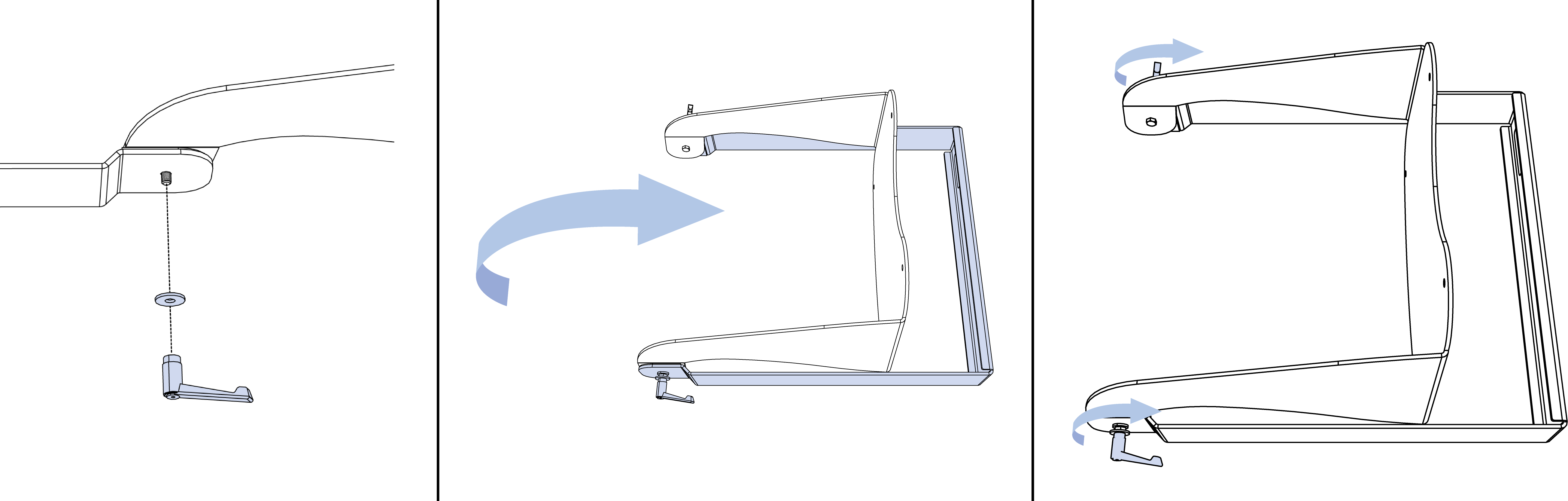
Set the yoke on an ULTRA-X80 loudspeaker, aligning the mounting holes of the yoke with the rigging points of the loudspeaker.
Secure the yoke to the loudspeaker with either the four knobs with washers (PN 45.287.061.01) or the four screws with washers (45.287.461.01), as shown in the figure below. Tighten the fasteners to at least 11 N-m (97 in-lb) of torque. Maximum torque is 13.3 N-m (120 in-lb).
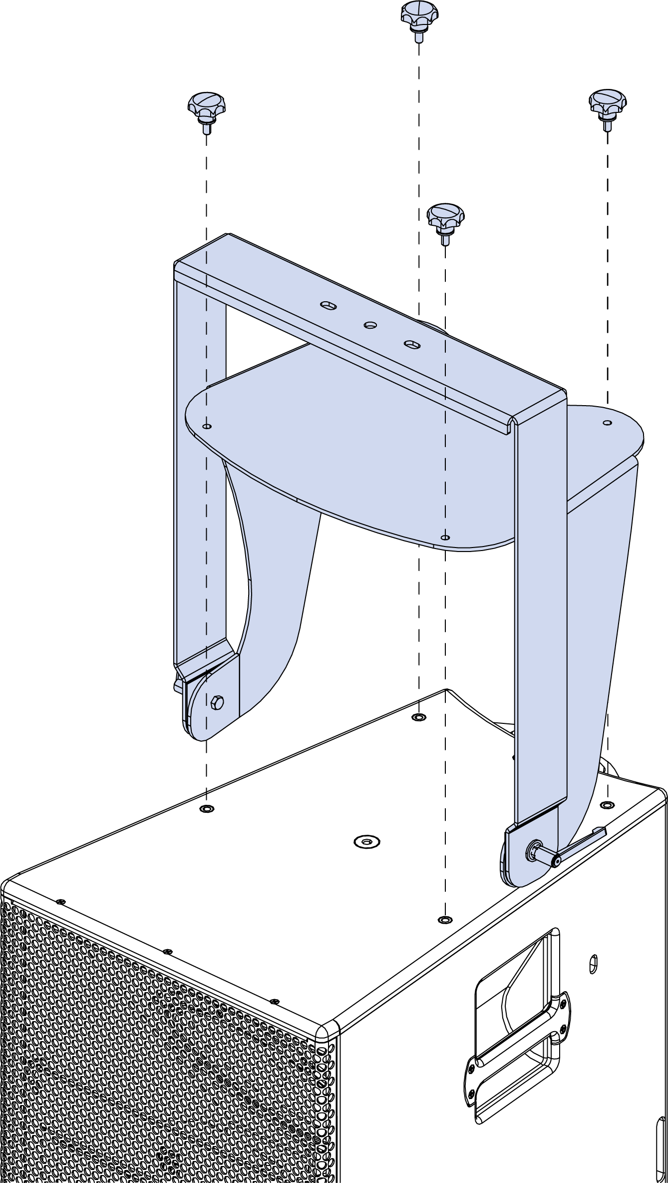
Attach Yoke to Loudspeaker - Knob/Washer Option Illustrated
MY-T1 Yoke Mounting Instructions
Attach a sufficiently rated clamp or other rigging hardware to the center mounting hole of the yoke, or mount the yoke with two sufficiently rated and sized fasteners through the two slotted holes next to the center mounting hole.
Suspend the loudspeaker from a sufficiently rated structural attachment point and attach the secondary or safety mounting point to a sufficiently rated structural attachment point. Adjust the horizontal aim of the loudspeaker and tighten the mounting hardware.
Loosen the machine handles or nuts to adjust the tilt of the loudspeaker, then tighten again. The rotation point of the yoke and the center of gravity of the loudspeaker are well aligned, minimizing the friction needed at the yoke rotation point to maintain the loudspeaker position.
Retain this document, along with the product warranty and rigging safety document, for reference.
MUB-T1 U-Bracket
The optional MUB-T1 U-Bracket enables a single ULTRA-X80 loudspeaker to be mounted to the floor or ceiling with a 5:1 safety factor. The u-bracket includes four holes on the loudspeaker connection arms to adjust the distance between the loudspeaker and mounting surface.
The MUB-T1 U-Bracket Kit includes two M8 machine handles for easy angle adjustment when temporarily deployed. For permanent installation, the included M8 nuts secure the u-bracket to the loudspeaker, minimizing the visual footprint. This accessory is available in custom colors. The fastening hardware is always black.

ULTRA-X80 Loudspeaker with MUB-T1 U-Bracket, Permanent Hardware (left), Temporary Hardware (right)
One ULTRA-X80 loudspeaker can be safely mounted with the MUB-T1 U-Bracket with a 5:1 safety factor. When mounting an ULTRA-X80 with the MUB-T1, the u-bracket must be secured to the mounting surface by one of the configurations listed in the table below.
Hole Location | Safety Factor |
|---|---|
Six 7.1 mm [0.28 in] perimeter holes | 5:1 |
Both 13.9 mm [0.55 in] inner holes | 5:1 |
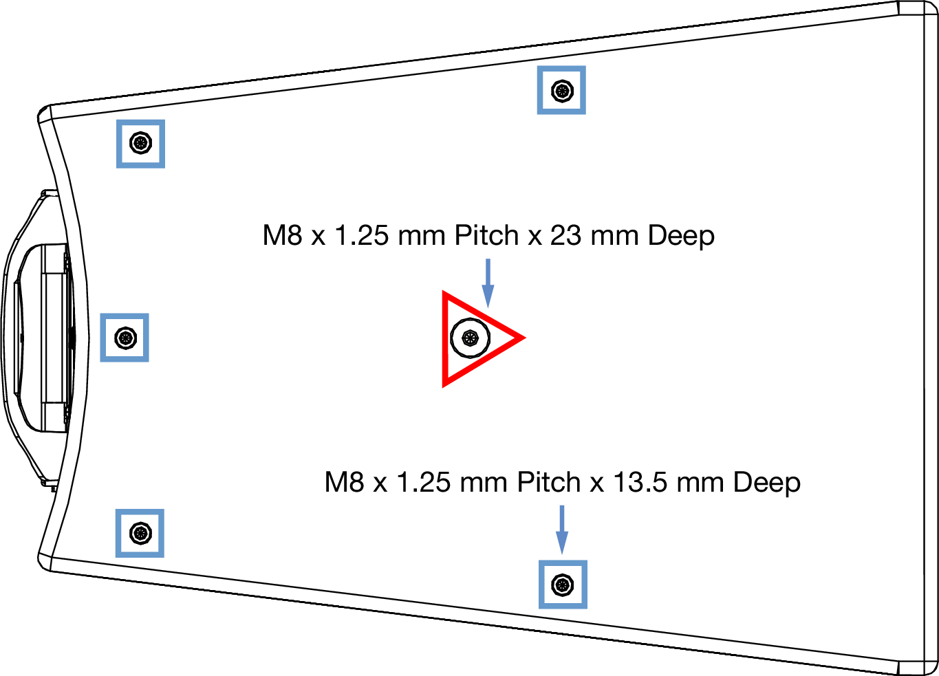
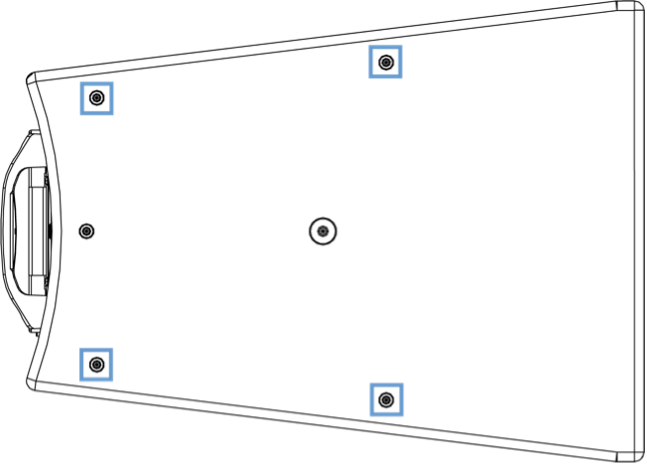
There are two sets of mounting points on the top of the MUB-T1. The blue squares shown in the figure below identify the six, 7.1 mm [0.28 in] diameter perimeter holes. The red triangles identify the two inner 13.9 mm [0.55 in] diameter mounting holes.
Once mounted to the structure, the two cable pass-through holes provide an unobtrusive routing path for the power and signal cables from above the mounting surface.
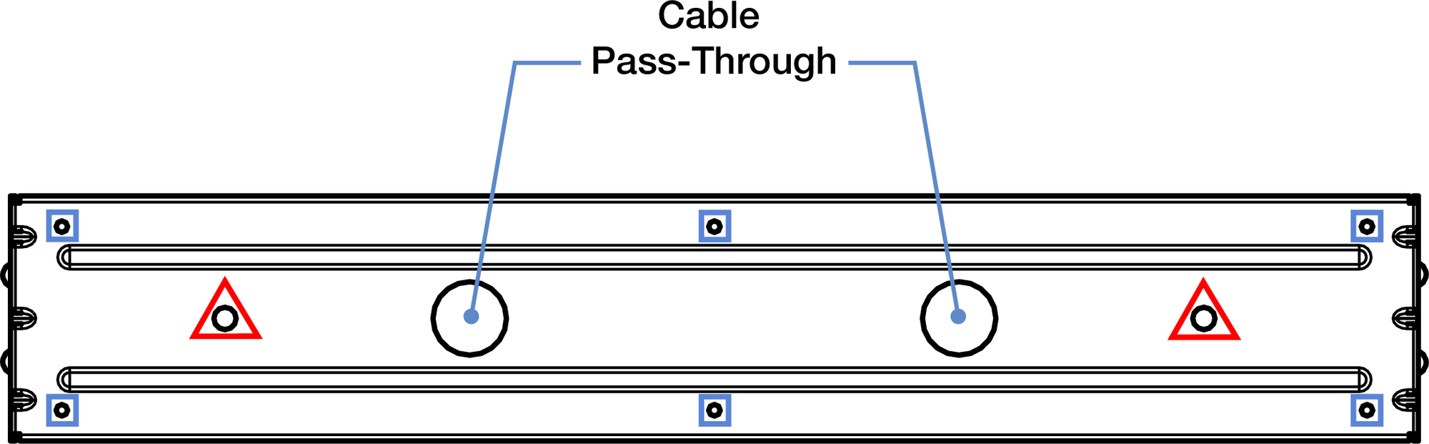
MUB-T1 Top Plate, Mounting Holes, and Cable Pass-Through Holes
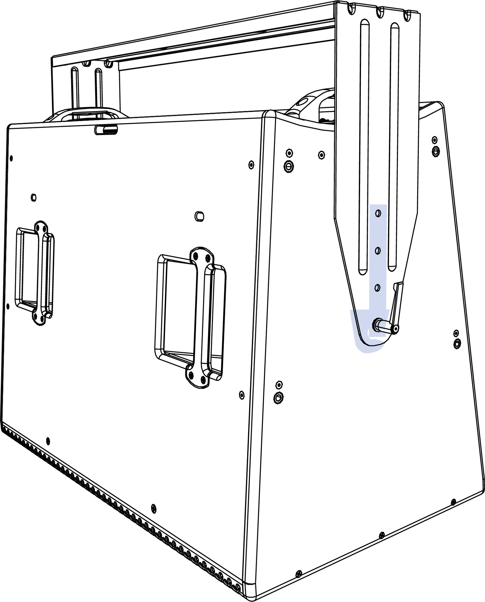
The ULTRA-X80 cabinet is designed to resist the accumulation of liquid in the internal cavities - exits are provided if it does. However, the mounting instructions must be closely followed for the exits to be effective. There are two drain holes and a drain slot on one side of the cabinet. The two holes on the side drain any accumulated liquid from two internal chambers. The slot prevents liquid from accumulating between the side and rear panels.
Caution
When mounting ULTRA-X80 loudspeakers horizontally, always mount the cabinet with the drain holes facing down.
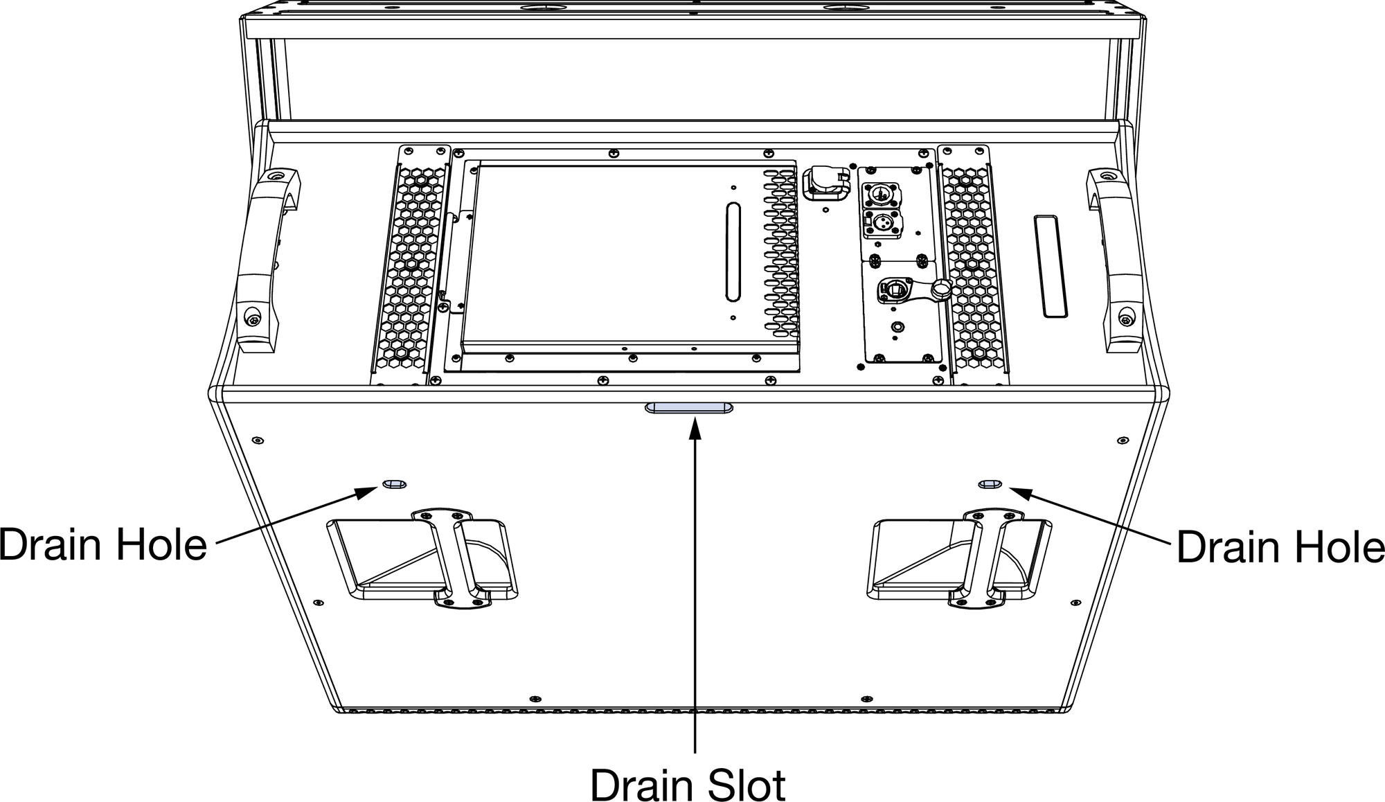
Horizontally Oriented ULTRA-X80 Loudspeaker, Drain Holes and Slot Highlighted
Caution
The MUB-T1 U-Bracket is not rated to be mounted in a vertical orientation, only horizontally, with the mounting plate surface perpendicular to gravity, usually to ceilings or floors.
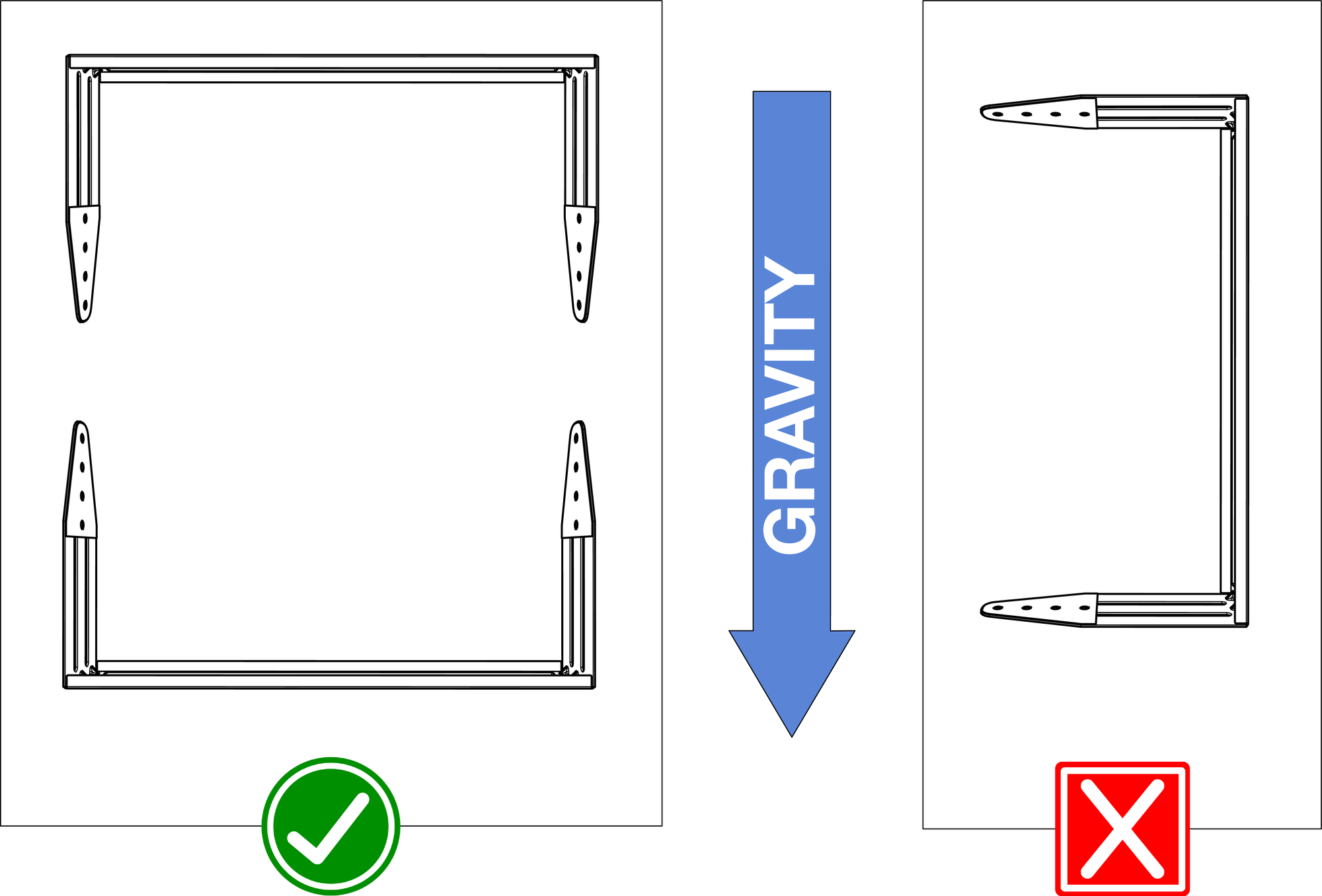
MUB-T1 U-Bracket - Horizontal Mounting Supported, Vertical Mounting Not Supported
MUB-T1 U-Bracket Dimensions
MUB-T1 Kit
The MUB-T1 U-Bracket kit includes the items listed in the table below.
Meyer Sound Part Number | Image | Qty | Description |
|---|---|---|---|
45.330.055.01 | 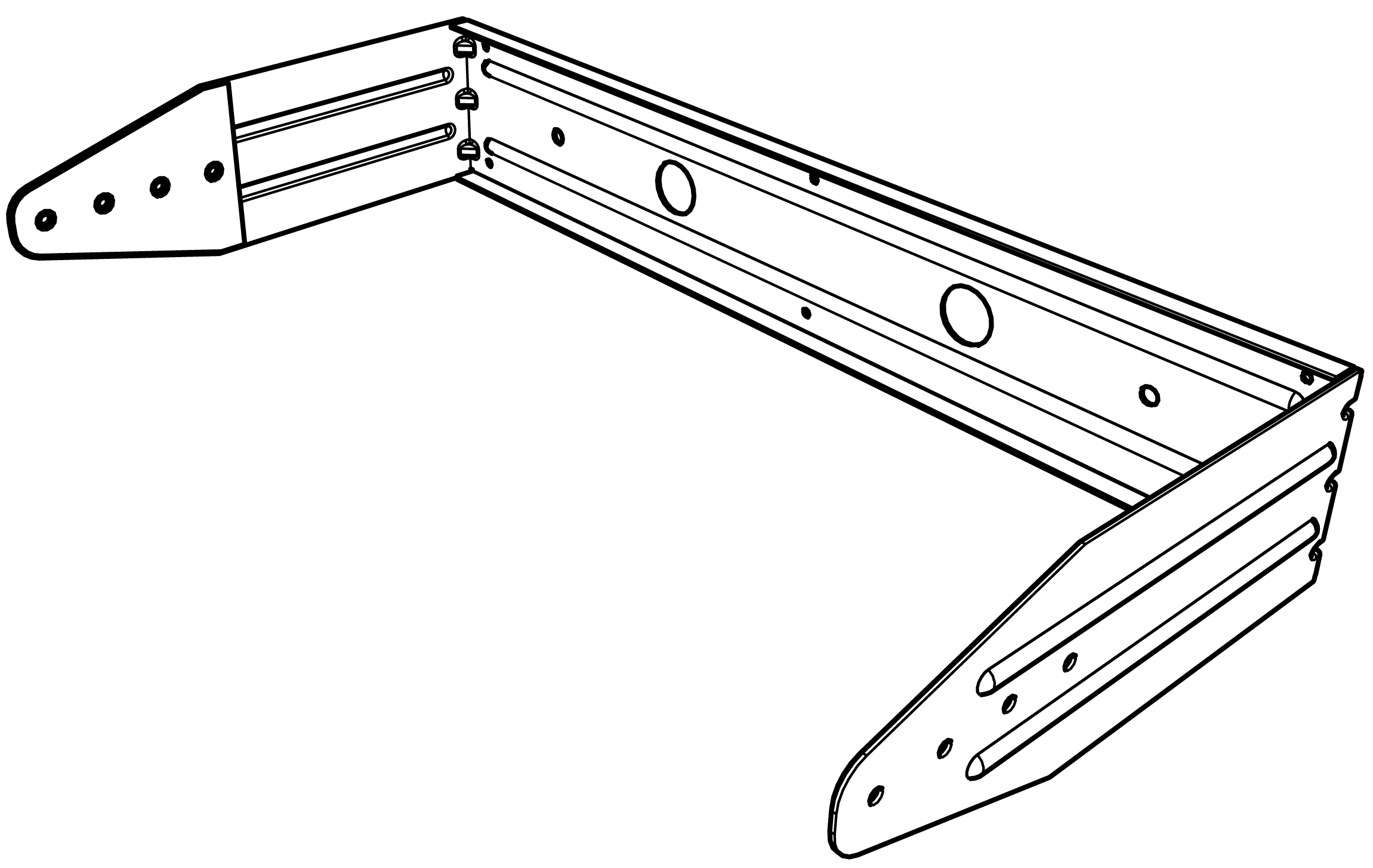 | 1 | MUB ASSEMBLY |
108.011 | 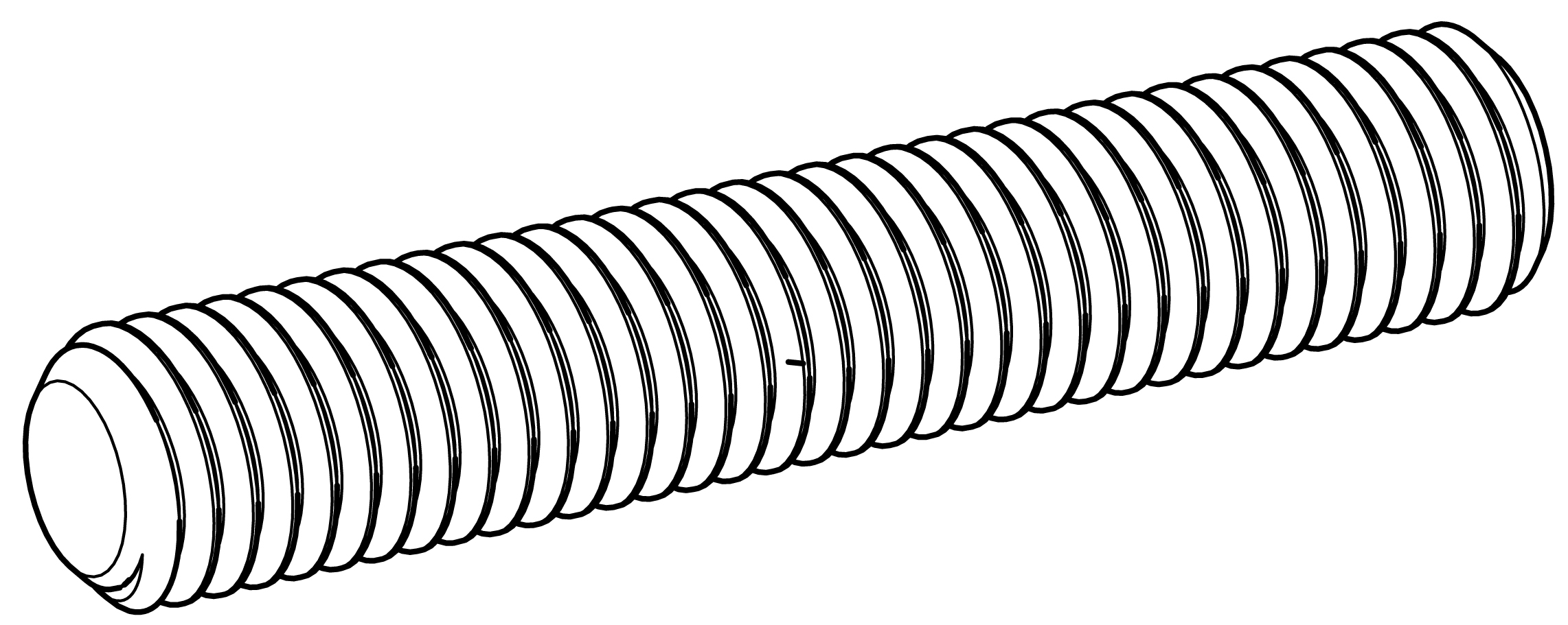 | 2 | SET SCREW, HEX , M8 x 45, STAINLESS, BLACK OXIDE |
113.532 | | 2 | WASHER, FLAT, 8.4 MM ID, 24 MM OD, 1.8 MM THICK, STAINLESS, BLACK |
124.066 | | 2 | MACHINE HANDLE M8 DIE CAST ZINC BLACK |
109.551 | | 2 | NUT, SMOOTH FLANGE M8-1.25, STAINLESS, BLACK OXIDE |
552.169 | -- | 1 | ALLEN WRENCH, 5/32-inch |
640.096 | -- | 1 | MED STRENGTH, REMOVABLE, THREADLOCKER, 0.5ML |
MUB-T1 U-Bracket Assembly Instructions
Determine which of the four mounting holes on the arms of the u-bracket are appropriate for the application, which is usually the mounting hole that will minimize the distance between the cabinet and the mounting surface while maintaining at least 15 cm (6 inches) of space between the rear of the cabinet and large surfaces for proper ventilation.
Lay the ULTRA-X80 cabinet on its side, with the drain holes and slot facing down.
Apply thread locker to the first three threads of the two set screws (PN 108.011).
Align the selected holes of the u-bracket arms with the center rigging point on each end of the cabinet and thread the set screw (PN 108.011) into the center rigging points.
Tighten the set screws with an Allen wrench (included) to a maximum of 13.3 N-m (120 in-lb) of torque.
Slide the flat washer (PN 113.532) onto the set screw, as shown in the figure below.
Thread either the Machine Handle (PN 124.066) or the M8 nut (PN 109.551) onto the set screw and tighten sufficiently to prevent cabinet rotation, maximum torque 13.3 N-m (120 in-lb).
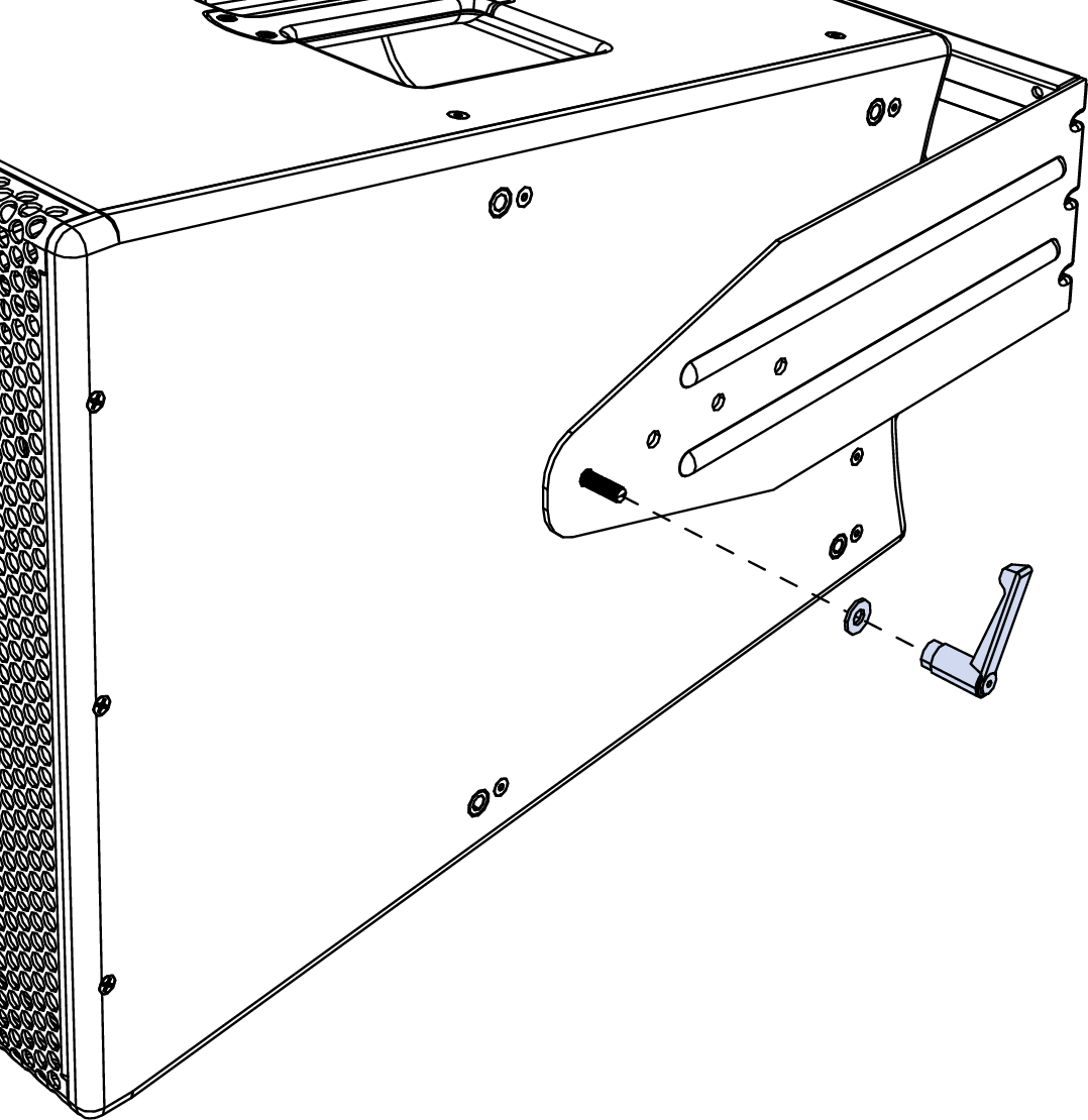
Washer and Machine Handle Installation
Limit On/Status LED error codes
The Limit On/Status LEDs located on the user panel indicate faults by blinking after the initial startup sequence. After powering the loudspeaker on, if these LEDs do not turn green after 15 seconds but instead flash or blink red, count the number of times it flashes between pauses and reference the table below to determine the fault. Faults are also displayed in Meyer Sound’s Nebra software and can be downloaded as a log file. In some cases, power-cycling or restarting the loudspeaker may clear the fault. For faults that are listed as non-clearable, contact your nearest Meyer Sound Service location with the loudspeaker model, serial number(s), and the fault indication.
Fault Indication (number of LED blinks) | Error Description | Trigger Condition(s) | Loudspeaker Action | Initial or Running | Clearable / Non-Clearable |
|---|---|---|---|---|---|
| Driver Harness Not Connected | Sense Circuit Open | Audio Muted | Initial | Non-Clearable |
| Sense circuit not compatible with firmware | Sense circuit mismatch with loudspeaker firmware type | Audio muted | Initial | Non-Clearable |
| Load fault compression driver, ch 1 | open failed driver | DSP reduces threshold for TPL and peak limiters | Running | Clearable |
| Load fault lower LF driver, ch 2a | open failed driver | DSP reduces threshold for TPL and peak limiters | Running | Clearable |
| Load fault upper LF driver, ch 2b | open failed driver | DSP reduces threshold for TPL and peak limiters | Running | Clearable |
| not used | ||||
| not used | ||||
| Fan controller not found | Fan controller not found | Audio muted | Initial | Non-Clearable |
| Amplifier not ready | Amplifier not passing audio | Audio muted | Running | Clearable |
| not used | ||||
| not used | ||||
| Within 20°C of amplifier thermal limit | High amplifier component temperatures | TPL reduced by 60% | Running | Clearable |
| Amplifier thermal limit exceeded | Maximum amplifier temperatures exceeded | Audio muted – high-voltage supply and amplifier turned off | Running | Clearable |
| DSP non-responsive | DSP not detected | No audio output | Initial | Non-Clearable |
| Board temperature sensor non-responsive | Temperature sensor not detected | Warning, no action | Initial or Running | Clearable |
| not used | ||||
| not used | ||||
| not used | ||||
| Wrong DSP for loudspeaker model | Could not verify correct DSP | No audio output | Initial | Non-Clearable |
| Communication failure | CAN startup message failure | No action – at startup only | Initial | Non-Clearable |
| AC Mains voltage > 160 V AC | RMS voltage exceeds threshold for one second | TPL reduced by 80% | Running | Clearable |
| not used | ||||
| not used | ||||
| SE/BTL Mode Check BTL unbal | Amp hardware not configured for X80 | No audio output | Initial | Non-Clearable |


