Operating Instructions — ULTRA-X20XP | 22XP | 23XP
Compact wide (ULTRA-X20XP), narrow (ULTRA-X22XP), and broad coverage (ULTRA-X23XP) loudspeakers
Meyer Sound’s ULTRA-X20 loudspeaker extends the award-winning, state-of-the-art ULTRA-X40 point source technology to a smaller version for size- and weight-critical applications. The ULTRA-X20XP model offers this exceptional audio performance in a compact self-powered package with a remote power supply.
The ULTRA-X20XP/22XP/23XP loudspeaker series features include:
An innovative, highly efficient class D amplifier that reproduces any sound source with linearity over a wide dynamic range.
A weight of only 27 lbs (12.3 kg) in a small cabinet size.
A concentric driver configuration with all the benefits of a coaxial driver, yet none of the disadvantages. This configuration also supports directional control of frequencies down to 600 Hz.
An extremely well-behaved rotatable horn that was designed for very precise, even coverage. This horn design, in conjunction with the concentric driver configuration, delivers the same pattern regardless of orientation.
The ULTRA-X20XP loudspeaker provides high power output, low distortion, and consistent polar response in a very compact, vented enclosure. The loudspeaker features two 5-inch cone low-frequency drivers and one 2-inch diaphragm compression driver coupled with a rotatable 110° x 50° Constant-Q horn.
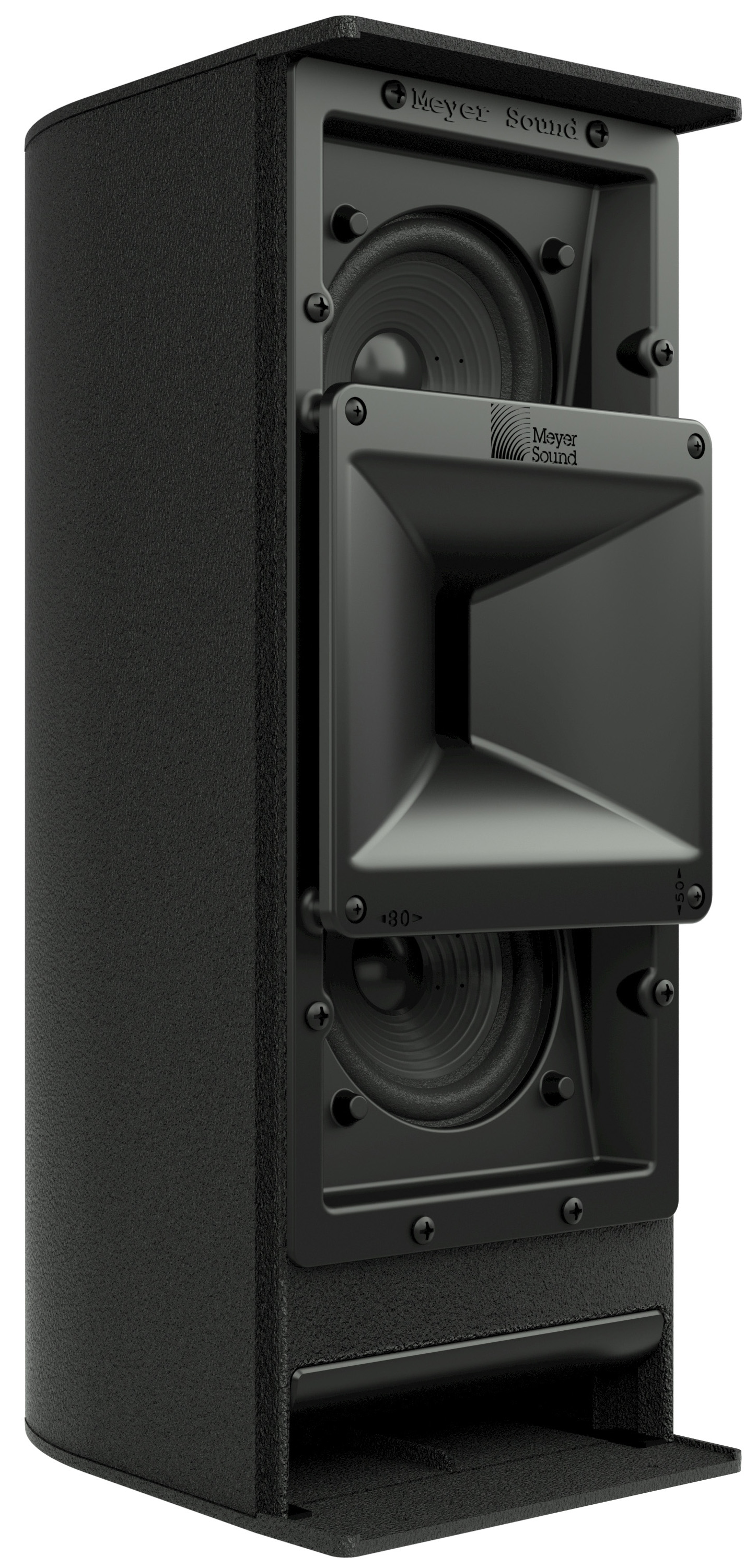
ULTRA-X20XP without Grille
A more controlled pattern is available on the ULTRA-X22XP model, which is fitted with a 80° x 50° Constant-Q horn. A broad coverage version, the ULTRA-X23XP, offers a 110° x 110° Constant-Q horn.
Because of its proprietary, high-frequency horn, the beamwidth remains consistent within close tolerances in both the horizontal and vertical planes, and across the horn’s operating frequency range. Uniformly predictable polar behavior takes much of the guesswork out of system design and assures optimal system performance.
A proprietary three-channel, class D digital power amplifier powers the ULTRA-X20 loudspeaker, which has a total peak power output of 860 watts. Audio processing includes electronic crossover, correction filters for phase and frequency response, and driver protection circuitry.
Phase-corrected electronics ensure flat acoustical amplitude and phase response, resulting in exceptional impulse response and precise imaging.
The ULTRA-X20XP version with IntelligentDC technology suits applications where AC power distribution is a limiting factor. It receives DC power and balanced audio from a Meyer Sound MPS power supply.
Meyer Sound builds the elegant, slightly curved enclosure out of aluminum with a slightly textured black finish. A powder-coated, round-perforated steel grille provides protection to the front of the loudspeaker.
The ULTRA-X20XP includes two integral M8 rigging points on each end to enable a variety of configurations including those requiring pole mounting, hanging individually from a single point, wall mounting or ceiling mounting. Optional rigging accessories include a U-bracket, yoke, 35 mm to M8 pole adapter, and a pinnable link on a channel that allows the hanging of a one or two units from a single pick-up point. (Three pinnable links are required to hang two units together—two between the loudspeakers and one on top.) It is also possible to mount the ULTRA-X20XP under an ULTRA-X40/42 using one MTC-X40 and one MTC-X20. The heat sink mounting holes provide additional mounting capabilities using third-party wall mount adapters with 5-inch by 2.75-inch (127 mm by 70 mm) hole patterns. Other options include weather protection and custom color finishes.
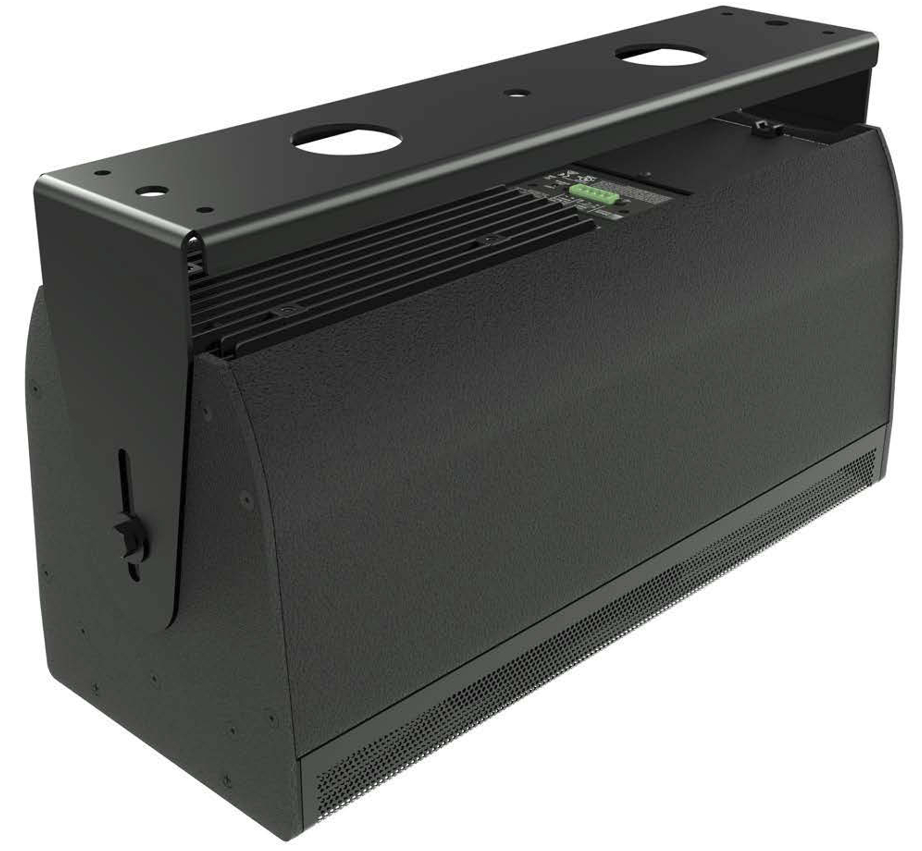
ULTRA-X20XP with MUB-X20 Ceiling Mount Position
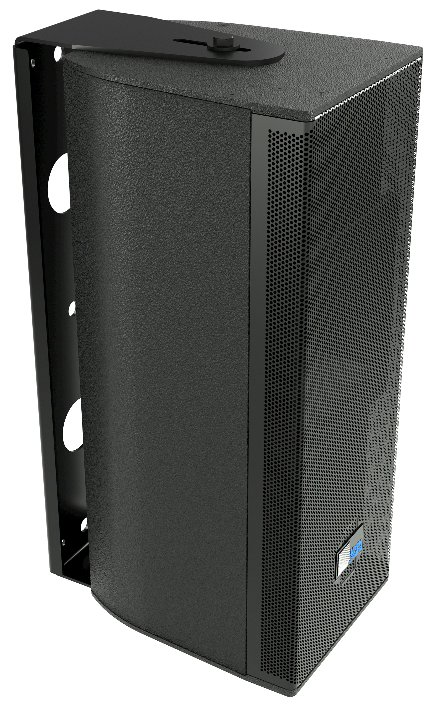
ULTRA-X20XP with MUB-X20 in Vertical Wall Mount Position
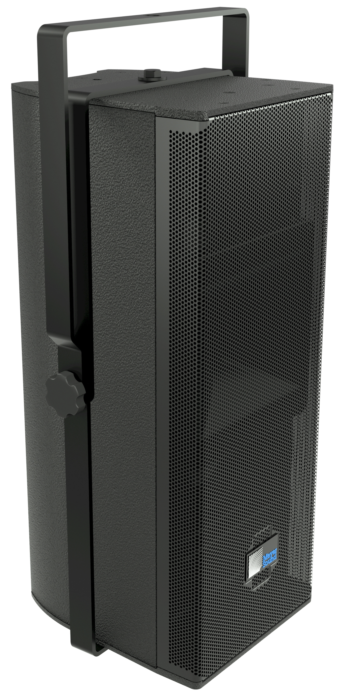
ULTRA-X20XP with MYA-X20 Mounting Yoke
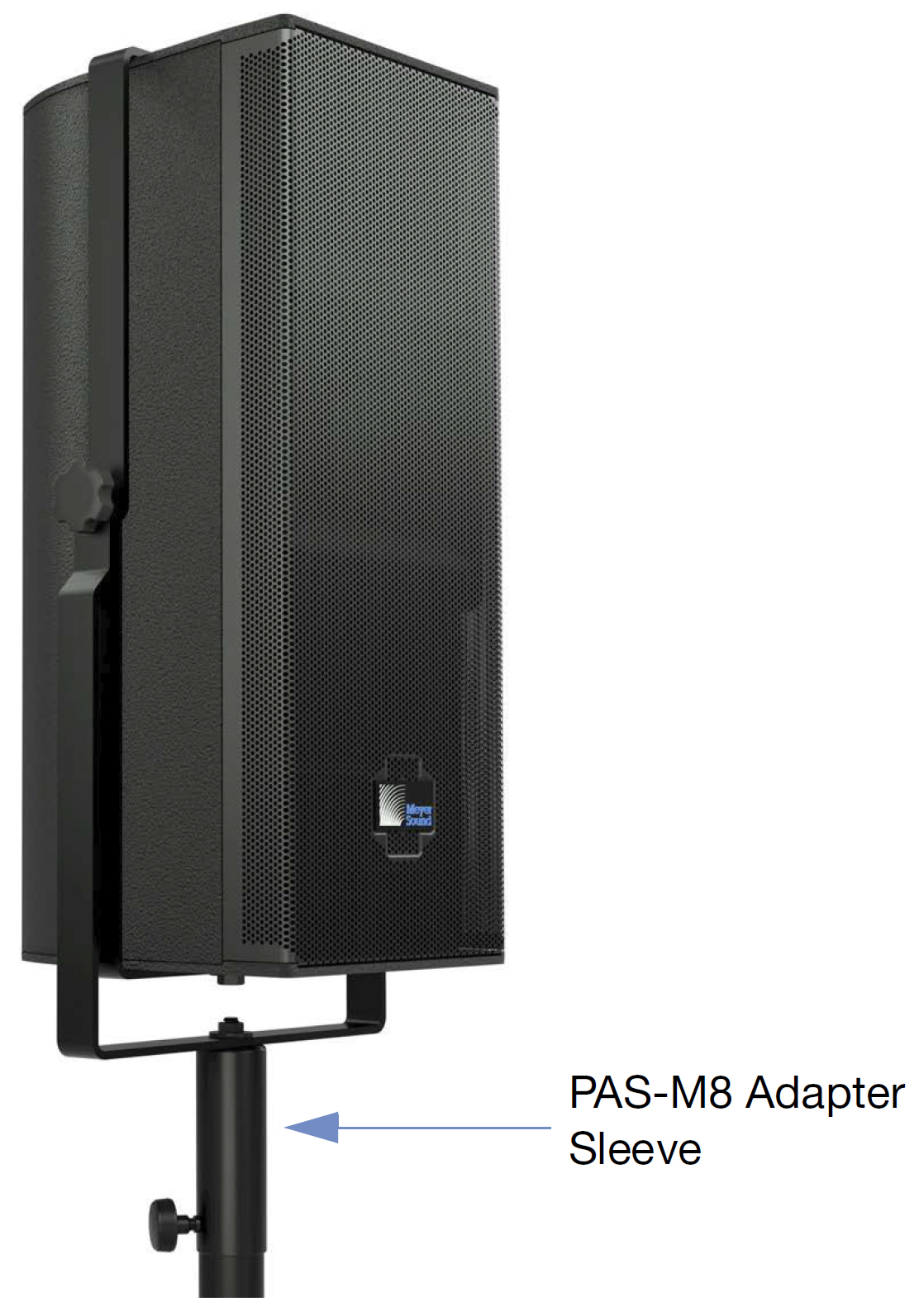
ULTRA-X20XP and MYA-X20 Pole-mounted with PAS-M8 Adapter Sleeve
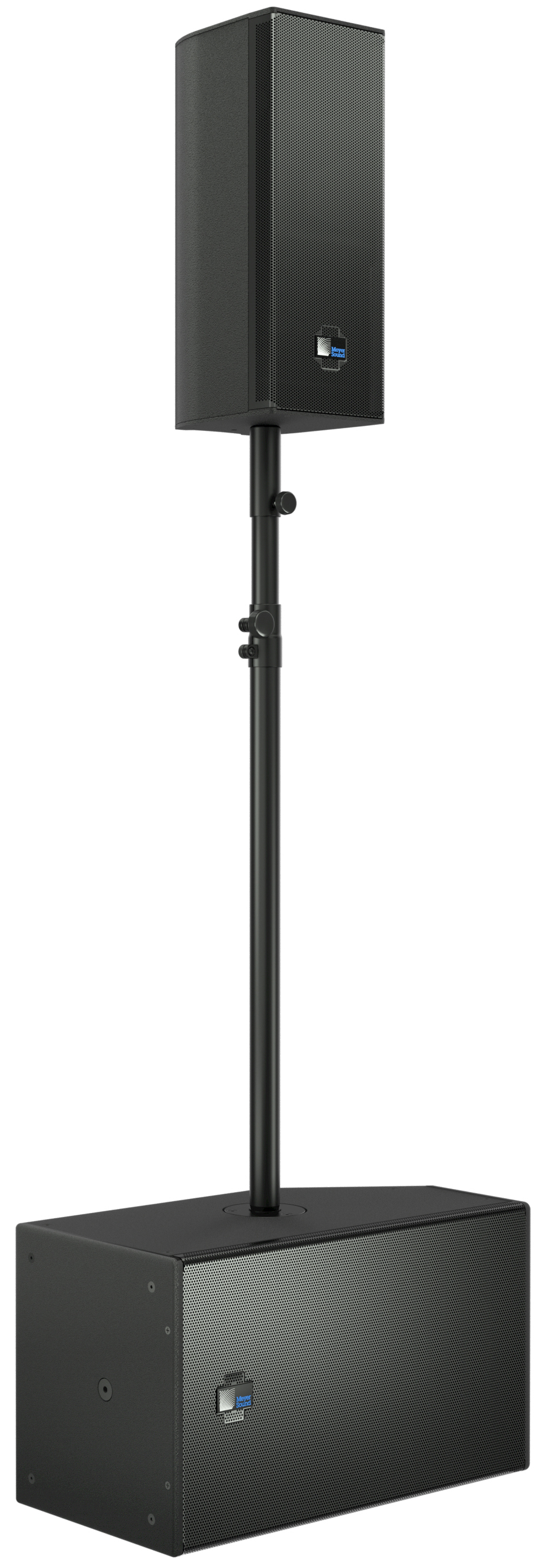
ULTRA-X20XP Pole-mounted on USW-112XP with PAS-M8 Adapter Sleeve
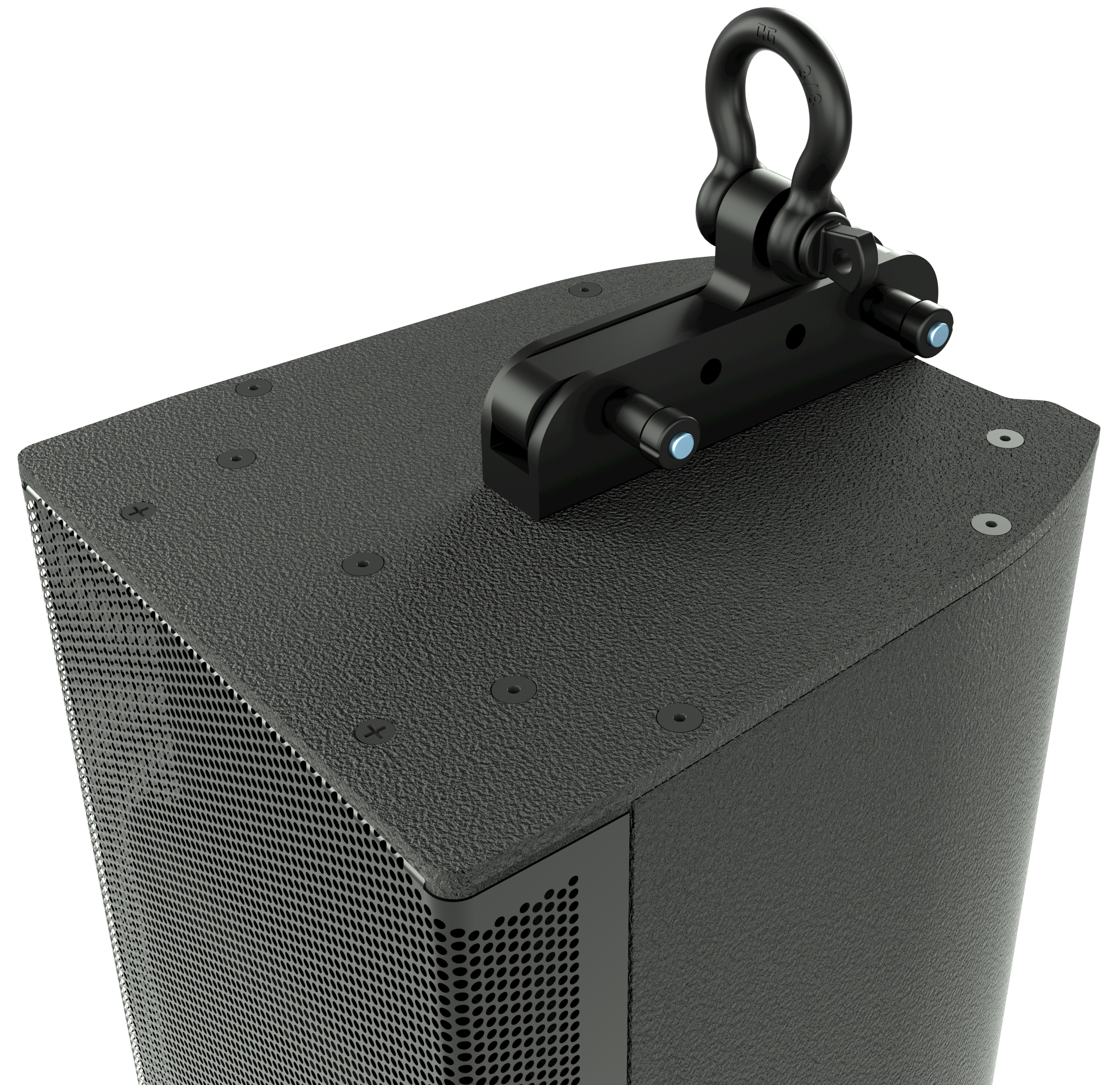
ULTRA-X20XP with MTC-X20 Top Channel Kit and Shackle
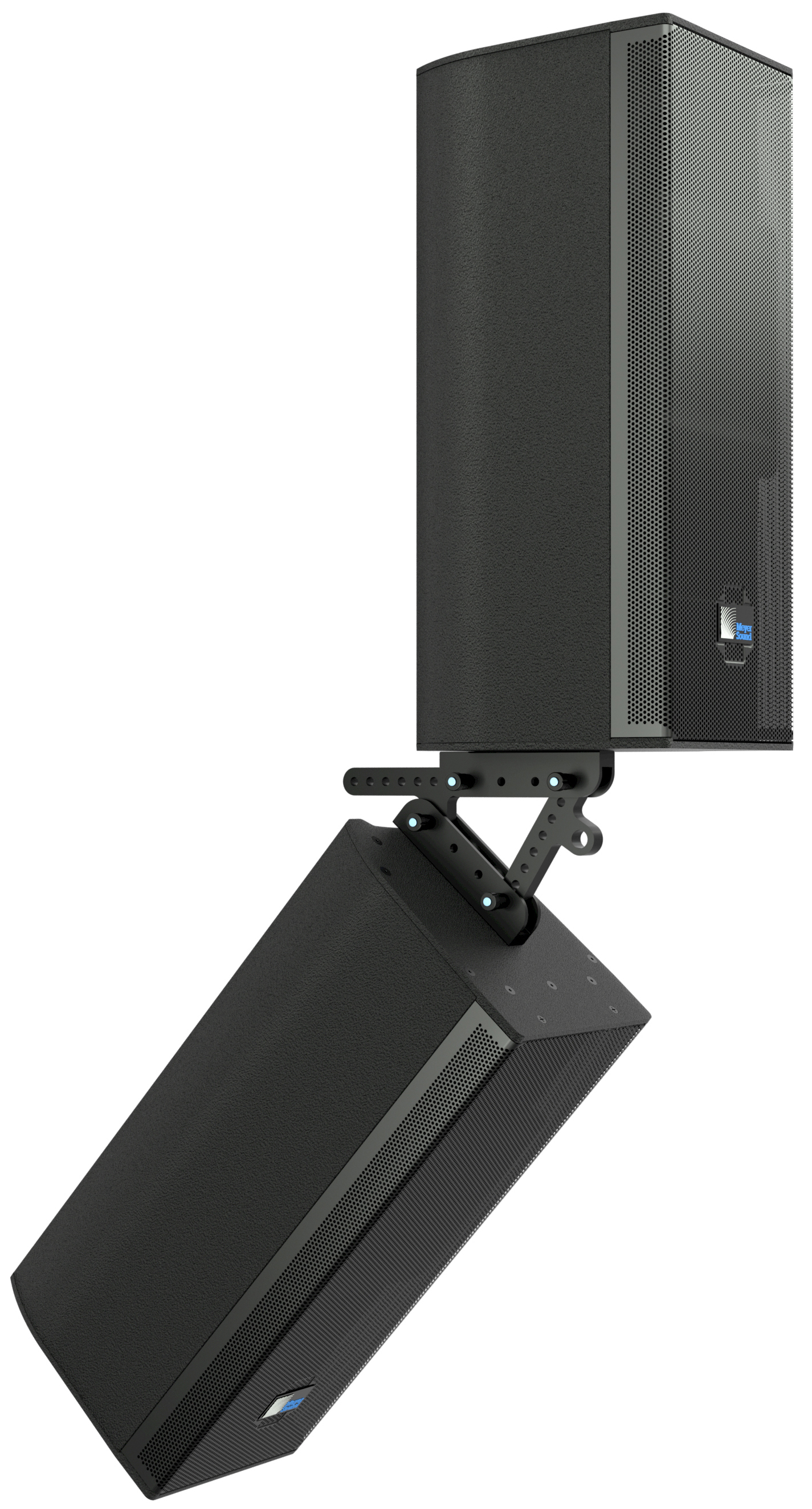
Two ULTRA-X20XP Rigged Together with Two MTC-X20 Top Channel Kits
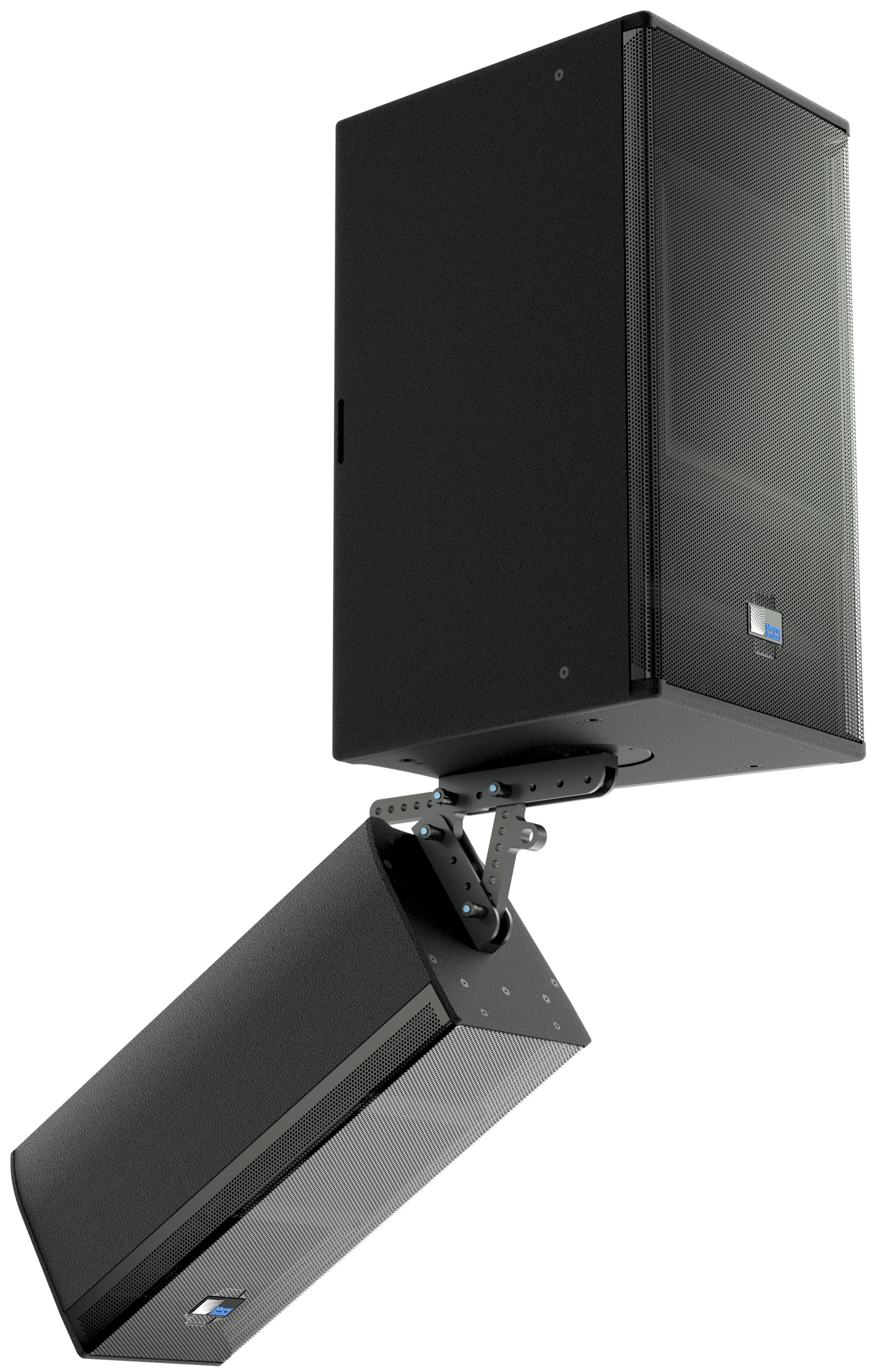
ULTRA-X20XP Mounted Beneath ULTRA-X40 using One MTC-X40 and One MTC-X20
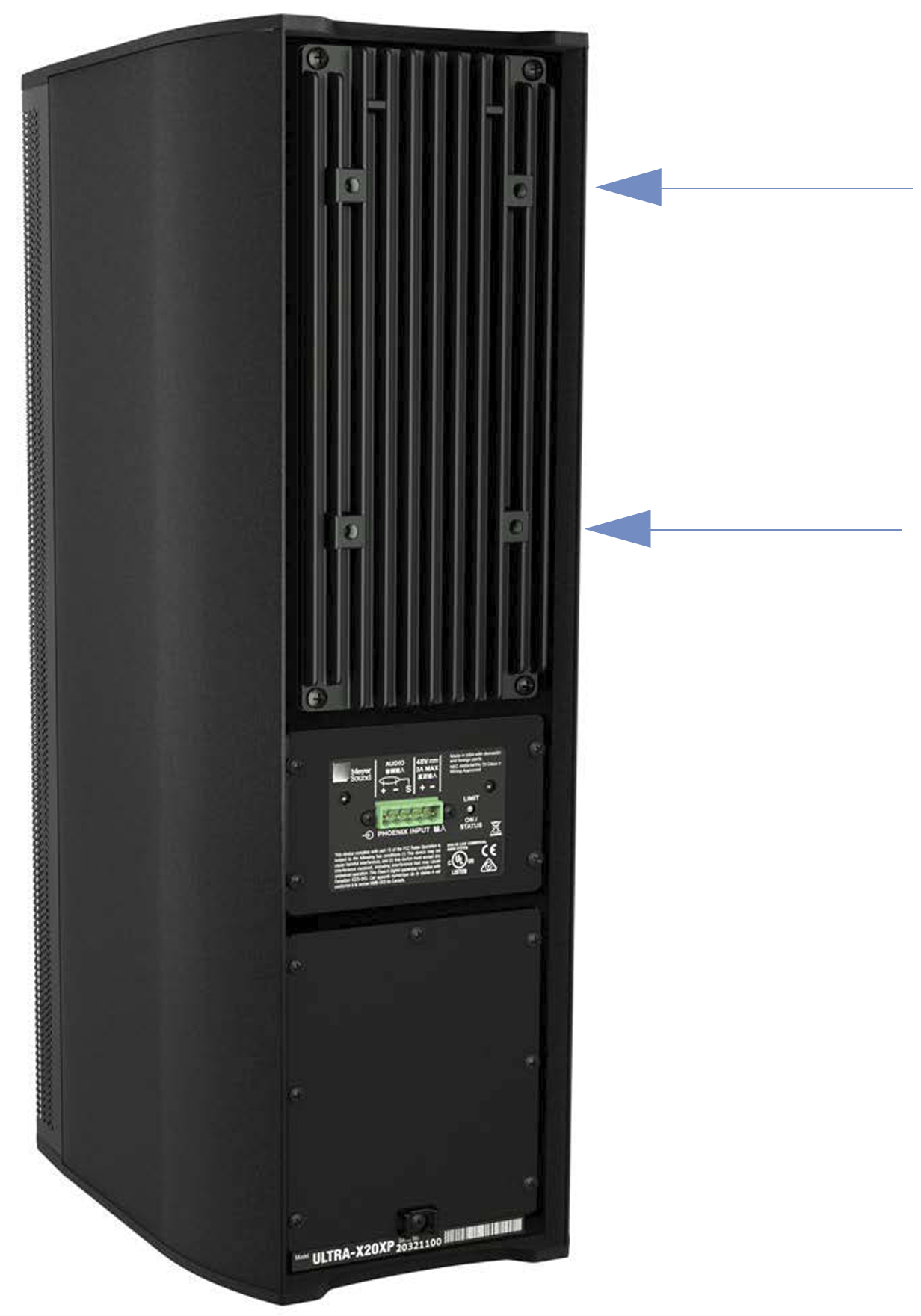
ULTRA-X20XP Heat Sink Third-party Accessory Mounting Capability 5-inch x 2.75-inch (127 mm x 70 mm) Hole Pattern
ULTRA-X20XP Loudspeaker
The ULTRA-X20XP requires an external Meyer Sound 48 V DC power supply. (See meyersound.com/product/mps for datasheets and details.) Using an external power supply eliminates the need for wiring conduits while still preserving the advantages of a self-powered loudspeaker system. The unit's onboard amplifier and signal-processing circuits are designed to store DC power and tolerate voltage drops, thereby accommodating long, light-gauge cable runs.
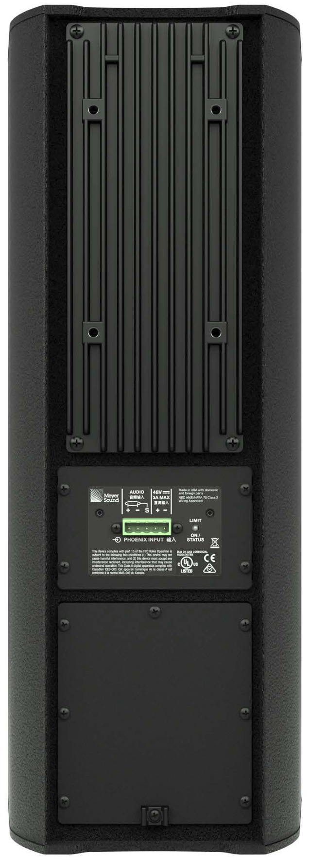
ULTRA-X20XP Rear View
ULTRA-X20XP Input Connector
The ULTRA-X20XP loudspeaker uses a Phoenix 5-pin male connector to receive DC power and balanced audio. The input connector’s five pins, two for DC power (-, +) and three for balanced audio (+, -, Shield/ground), are clearly labeled on the ULTRA-X20XP rear panel. shown in the figure below.
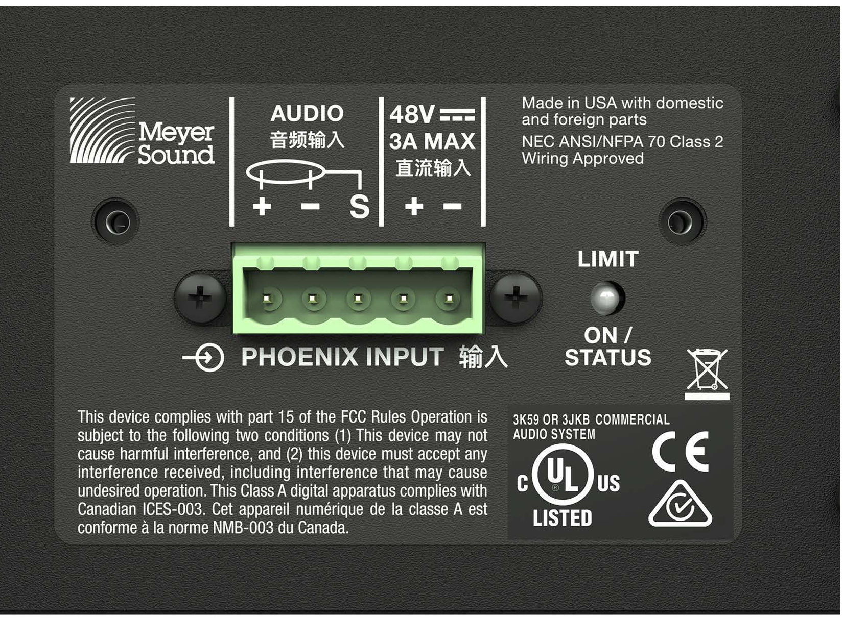
ULTRA-X20XP Rear Panel with Phoenix 5-pin Male Connector
Caution
When wiring ULTRA-X20XP loudspeaker cables, it is extremely important that each pin be wired correctly. Make sure the 48 V DC from the external power supply is wired directly (and only) to the 48 V DC pins on the ULTRA-X20XP loudspeaker connector, and that the polarity is observed (- to -, + to +) to avoid damaging the loudspeaker. Make sure to wire the audio pins correctly or system performance will be compromised.
Note
Also see the IntelligentDC Products Wiring Verification Installation Instructions (PN 17.902.040.01).
ULTRA-X20XP LED
The ULTRA-X20XP uses the three-color LED on its rear panel to indicate the loudspeaker’s status.
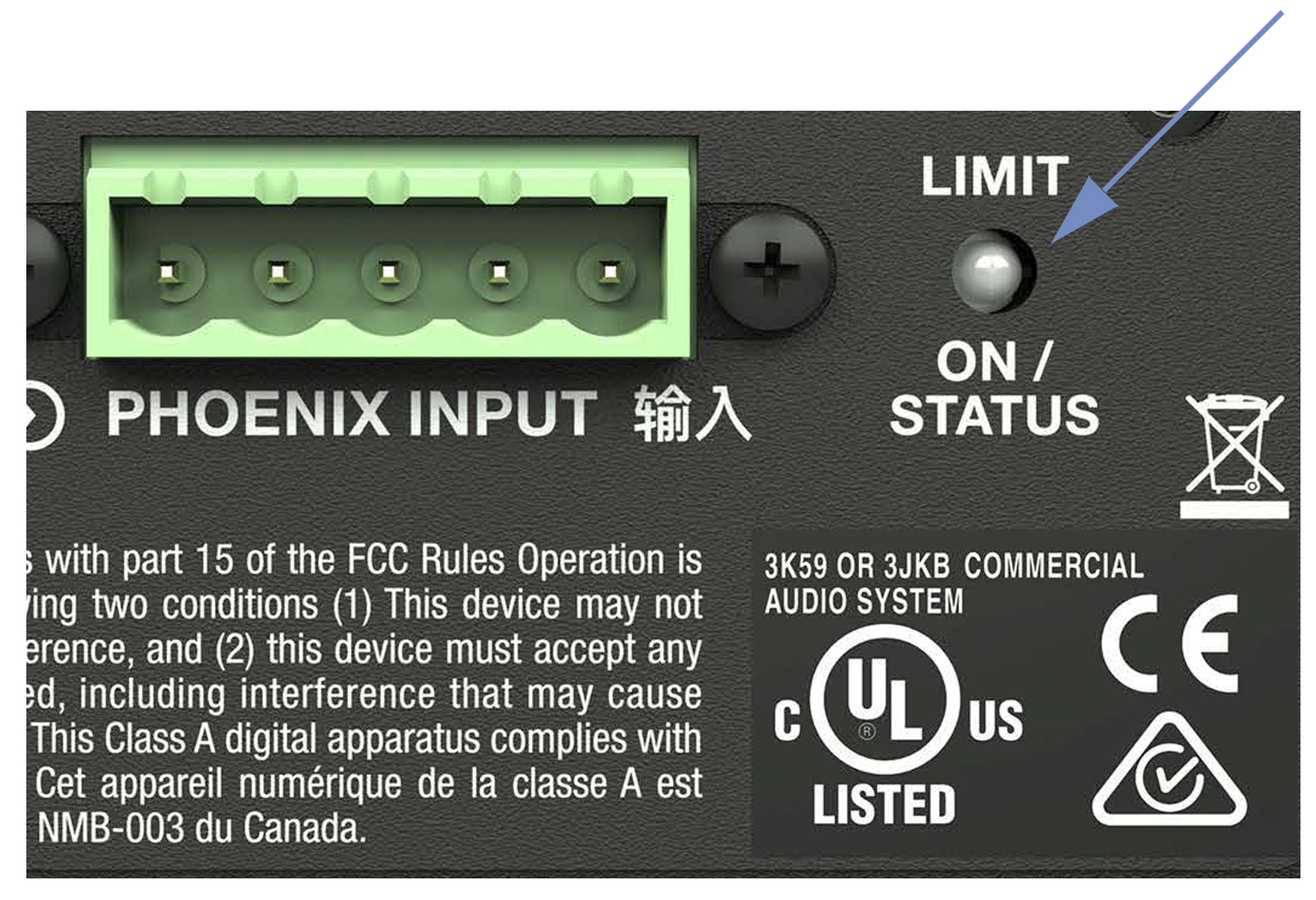
ULTRA-X20XP LED - Limit and On/Status Indicator
Power On (Green)
When powering up the ULTRA-X20XP loudspeaker, the following startup events occur and are indicated by the LED:
The LED flashes all colors during power-up.
After a few seconds, the LED lights solid green, indicat- ing the loudspeaker is ready to reproduce audio.
Caution
If the power-up sequence leaves the LED flashing multiple colors or solid red, and it does not produce audio, the loudspeaker has encountered an error and may need to be serviced. Contact Meyer Sound Technical Support.
If the power-up sequence leaves the LED solid red and the loudspeaker outputs audio, its voltage may have dropped below 25 V DC. Cease operation immediately and verify its power supply and cabling.
Limiting (Yellow)
The ULTRA-X20XP LED lights solid yellow to indicate limiting is engaged for the high-frequency channel. The LED flashes yellow to indicate limiting is engaged for the low-frequency channels.
The ULTRA-X20XP LED turns yellow when the loudspeaker’s signal rises 2 dB above the limiting threshold, indicating that a safe, optimal level has been exceeded.
When limiting is engaged for a channel, its gain is reduced. The limiter protects the drivers and prevents signal peaks from causing excessive distortion in the amplifier, thereby preserving headroom and maintaining a smooth frequency response at high levels. When source levels return to normal below the limiter’s threshold, the LED turns green and limiting ceases.The ULTRA-X20XP performs within its acoustical specifications at normal temperatures when the ULTRA-X20XP LED is green, or when limiting is not continuous. During continuous limiting, the loudspeaker is nearing its operational limits, resulting in the following effects:
Increasing the input level has no effect.
Distortion increases due to clipping and nonlinear driver operation.
The drivers are subjected to excessive heat and excursion, which compromises their life span and may eventually damage them.
Caution
If the ULTRA-X20XP loudspeakers in a system begin to limit before reaching the desired SPL, Meyer Sound recommends adding more loudspeakers to the system to achieve the desired SPL without exposing them to the hazardous conditions listed above.
ULTRA-X20XP Temperature and Limiting
The ULTRA-X20XP LED also lights solid yellow when its heat sink temperature reaches its maximum heat dissipation. Even though the ULTRA-X20XP continues to operate while the LED is yellow, the limiter threshold is lowered, causing the output level to be lowered by 3 dB, to prevent the loudspeaker from overheating. When the temperature of the heat sink cools, the LED changes from yellow to green and the limiter threshold returns to normal.
Clipping (Red)
The ULTRA-X20XP LED turns red when the loudspeaker’s input stage clips, causing the amplifier to overload. The source level must be reduced.
Caution
If the ULTRA-X20XP LED turns solid red and the loudspeaker continues to output audio, though at reduced levels, the loudspeaker’s voltage may have dropped below 25 V DC. Cease operation immediately and verify its power supply and cabling.
ULTRA-X20XP Current Draw and Cable Requirements
Each ULTRA-X20XP loudspeaker draws a maximum current of 0.9 A continuous and 3.5 A peak from its external 48 V DC power supply. The current draw for the ULTRA-X20XP is dynamic and fluctuates as operating levels change. The cabling between the ULTRA-X20XP and its external power supply adds resistance and hence causes a voltage drop at the loudspeaker. Because lower DC voltages compromise amplifier performance (peak SPL), and in some cases frequency response, use short cables to minimize the cable resistance. For long cable runs, use a large cable gauge for DC power and a separate balanced audio cable for audio. For more information, see Long Cable Runs with Separate Cable for DC Power and Audio.
Cable Lengths and Cable Gauges for ULTRA-X20XP Loudspeakers
Cable lengths up to 150 feet between the ULTRA-X20XP and its external power supply are supported with only 1 dB of peak SPL loss using 18 AWG wire. Longer cable lengths are possible with heavier gauge wires (see the tables below).
Cable Gauge | Resistance (/ft) | Approximate Max. Length |
|---|---|---|
12 AWG | 0.0016 | 600 ft |
14 AWG | 0.00253 | 375 ft |
16 AWG | 0.00402 | 237 ft |
18 AWG | 0.00636 | 150ft |
20 AWG | 0.01008 | 87 ft |
Cable Gauge | Resistance (/ft) | Approximate Max. Length |
|---|---|---|
2.50 mm2 | 0.0052 | 157 m |
1.50 mm2 | 0.01076 | 87 m |
1.00 mm2 | 0.02087 | 45 m |
0.75 mm2 | 0.03307 | 27 m |
Note
The total cable resistance between the ULTRA-X20XP and its external power supply should not exceed 2 Ω.
Calculating the Maximum Cable Length
The maximum cable length for a ULTRA-X20XP can be calculated with the following formula:
maximum length = 2 Ω / (2 * cable resistance in Ω/ft)
For example, the maximum length of an 18 AWG cable with a resistance of 0.00636 Ω/ft is 157.2 feet [2 /(2 * 0.00636)].
Wiring ULTRA-X20XP Loudspeaker Cables with Belden 1502 Cable (or equivalent)
The most convenient method of wiring ULTRA-X20XP loudspeaker cables is with a multiconductor cable such as Belden1502, which has dedicated conductors for DC power and balanced audio in a single jacket. When wiring ULTRA-X20XP loudspeaker cables with Belden1502, use the conventions illustrated in Figure4 and described in Table3.
The thicker red and black wires (18 AWG) are for DC power. Cables can be up to 150 ft with just 1 dB of peak SPL loss.
The blue, white, and shield drain wires (shielded together) are for audio.

Belden 1502 Composite Cable
Cable Gauge | Resistance (Ω/m) | Approximate Max. Length |
|---|---|---|
2.50 mm2 | 0.0052 | 157 m |
1.50 mm2 | 0.01076 | 87 m |
1.00 mm2 | 0.02087 | 45 m |
0.75 mm2 | 0.03307 | 27 m |
Wire | Signal | Gauge |
|---|---|---|
Red | DC power (+) | 18 AWG |
Black | DC power (–) | 18 AWG |
White | Balanced audio (+) | 22 AWG |
Blue | Balanced audio (–) | 22 AWG |
Shield drain | Balanced audio, (shield) | 24 AWG |
Caution
Make sure the 48 V DC from the external power supply is wired directly (and only) to the 48 V DC pins on the ULTRA-X20XP loudspeaker connector, and that the polarity is observed (- to -, + to +) to avoid damaging the loudspeaker. Make sure to wire the audio pins correctly or system performance will be compromised.
Long Cable Runs with Separate Cable for DC Power and Audio
For installations where Belden 1502 is not feasible, or for installations that require cable runs longer than 150 ft, separate cables for DC power and balanced audio may be used: a large-gauge cable for DC and a high-quality, balanced audio cable for audio. The separate cables attach to the Phoenix connector at the loudspeaker, as shown in the figures below. DC power cable runs longer than 150 ft require cable gauges larger than 18 AWG; see Cable Lengths and Cable Gauges for ULTRA-X20XP Loudspeakers.

Phoenix Connector with Separate Power and Audio Cables

Separate Cables for DC Power and Balanced Audio
Connecting to an External Meyer Sound Power Supply
ULTRA-X20XP loudspeakers require an external Meyer Sound IntelligentDC power supply. The MPS-488HP is a 19-inch (1RU) unit that distributes DC power and balanced audio to ULTRA-X20XP speakers or other Meyer Sound IntelligentDC loudspeakers. Composite multi-conductor cables (e.g., Belden® 1502) can deliver both DC power and balanced audio. The MPS-488HP can connect to Meyer Sound’s RMS remote monitoring system. The MPS-488HP receives eight channels of balanced audio from its XLR female Channel Inputs. It routes the audio, along with 48 V of DC power, to its eight Channel Outputs. The MPS-488HP can drive up to eight ULTRA-X20XP loudspeakers.
The MPS-482HP is a 1RU, half-rack-width unit with two input channels and two output channels that is ideal for applications requiring a small channel count.
Use composite cables (such as Belden 1502 or equivalent) wired for both DC power and balanced audio and outfitted with the appropriate connectors.
To connect ULTRA-X20XP loudspeakers to the MPS-488HPp, use Phoenix 5-pin female to Phoenix 5-pin female cables.
Tip
See meyersound.com/product/mps for more details about Meyer Sound IntelligentDC power supplies.
Cable lengths up to 150 feet for DC power are possible when using 18-AWG wire, with just 1 dB of loss in peak SPL. Longer cable runs are possible for moderate applications that do not drive the loudspeakers to maximum output, or for installations with heavier gauge wires. The use of composite multiconductor cables (such as Belden 1502 or equivalent) allows a single cable to carry both DC power and balanced audio to the ULTRA-X20XPs.
Power off the MPS-488HP.
Use balanced XLR cables to connect audio sources from a mixer or processor to the MPS-488HP Channel Inputs.
Use the MPS-488HP Link switches to route Channel Inputs to the desired Channel Outputs.
Tip
See the MPS-488HP Operating Instructions, PN 05.205.005.01).
Connect the ULTRA-X20XP loudspeakers to the MPS-488HP Channel Outputs, as shown in the figure below.
Use composite cables (such as Belden1502 or equivalent) wired for both DC power and balanced audio and outfitted with the appropriate connectors.
To connect ULTRA-X20XP loudspeakers to the MPS-488HPp, use Phoenix 5-pin female to Phoenix 5-pin female cables.
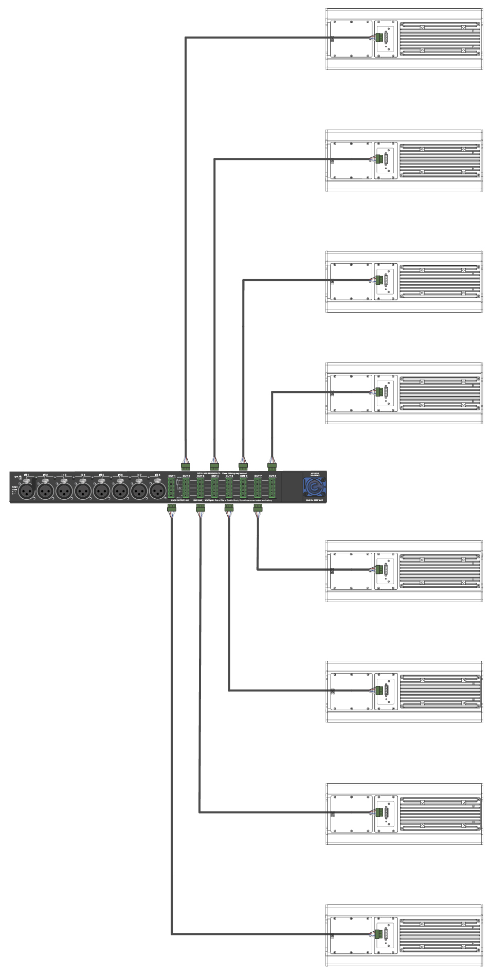
MPS-488HPp with Eight ULTRA-X20XP Loudspeakers
Tip
It is possible to use a two-conductor cable for DC power and a three-conductor cable for balanced audio with both cables attached to a single Phoenix connector on each end. This approach supports use of a larger gauge DC cable, which allows longer cable runs (see Long Cable Runs with Separate Cable for DC Power and Audio).
Caution
Make sure ULTRA-X20XP loudspeaker cables are wired correctly. For details about assembling loudspeaker cables, see Assembling Phoenix Loudspeaker Cables.
Power on the MPS-488HP and monitor the LEDs on the front panel to verify connections. For information about the MPS-488HP LEDs, refer to the MPS-488HP Operating Instructions (PN 05.205.0058.01).
Check the LEDs on the ULTRA-X20XP rear panels and verify they are green (ready to reproduce audio).
Enable output from the audio sources (from the mixer or processor) connected to the MPS-488HP.
Note
Connecting to an MPS-482HP power supply is similar. Refer to the MPS-482HP Operating Instructions (PN 05.285.005.01) for complete information. Also see the IntelligentDC Products Wiring Verification Installation Instructions (PN 17.902.040.01).
QuickFly Rigging
The ULTRA-X20XP, ULTRA-X22XP, and ULTRA-X23XP loudspeakers are compatible with Meyer Sound’s QuickFly system, a comprehensive collection of custom-designed rigging, flying, and mounting options. Comprised of rugged, reliable, and easy-to-configure components, QuickFly enables deployment of ULTRA-X20XP/22XP/23XP loudspeakers as either individual loudspeakers or as two-speaker clusters at precise angles to take full advantage of their directional components.
Important Safety Considerations
When installing Meyer Sound loudspeakers, the following precautions should always be observed:
All Meyer Sound products must be used in accordance with local, state, federal, and industry regulations. It is the owner’s and user’s responsibility to evaluate the reliability of any rigging method for their application. Rigging should only be carried out by experienced professionals.
Use mounting and rigging hardware that has been rated to meet or exceed the weight being hung.
Make sure to attach mounting hardware to the building's structural components (studs or joists), and not just to the wall surface. Verify that the building's structure and the anchors used for the installation will safely support the total weight of the mounted loudspeakers including the rigging components.
Use mounting hardware appropriate for the surface where the loudspeaker will be installed.
Make sure bolts and eye bolts are tightened securely. Meyer Sound recommends using medium-strength blue thread locker on eye bolt threads and safety cables.
Inspect mounting and rigging hardware regularly. Immediately replace any worn or damaged components.
Caution
When pole-mounting an ULTRA-X20XP onto a USW-112XP, to keep it stable, do not lift the ULTRA-X20XP higher than 44 inches from the top of the USW-112XP. This limit is due to the small footprint and light weight of the USW-112XP.
Rigging Points
The top and bottom aluminum plates for the ULTRA-X20XP/22XP/23XP cabinet include rigging points that provide two M8 x 1.25 threaded holes (on each end) for easy connection to QuickFly rigging and third-party mounting options.
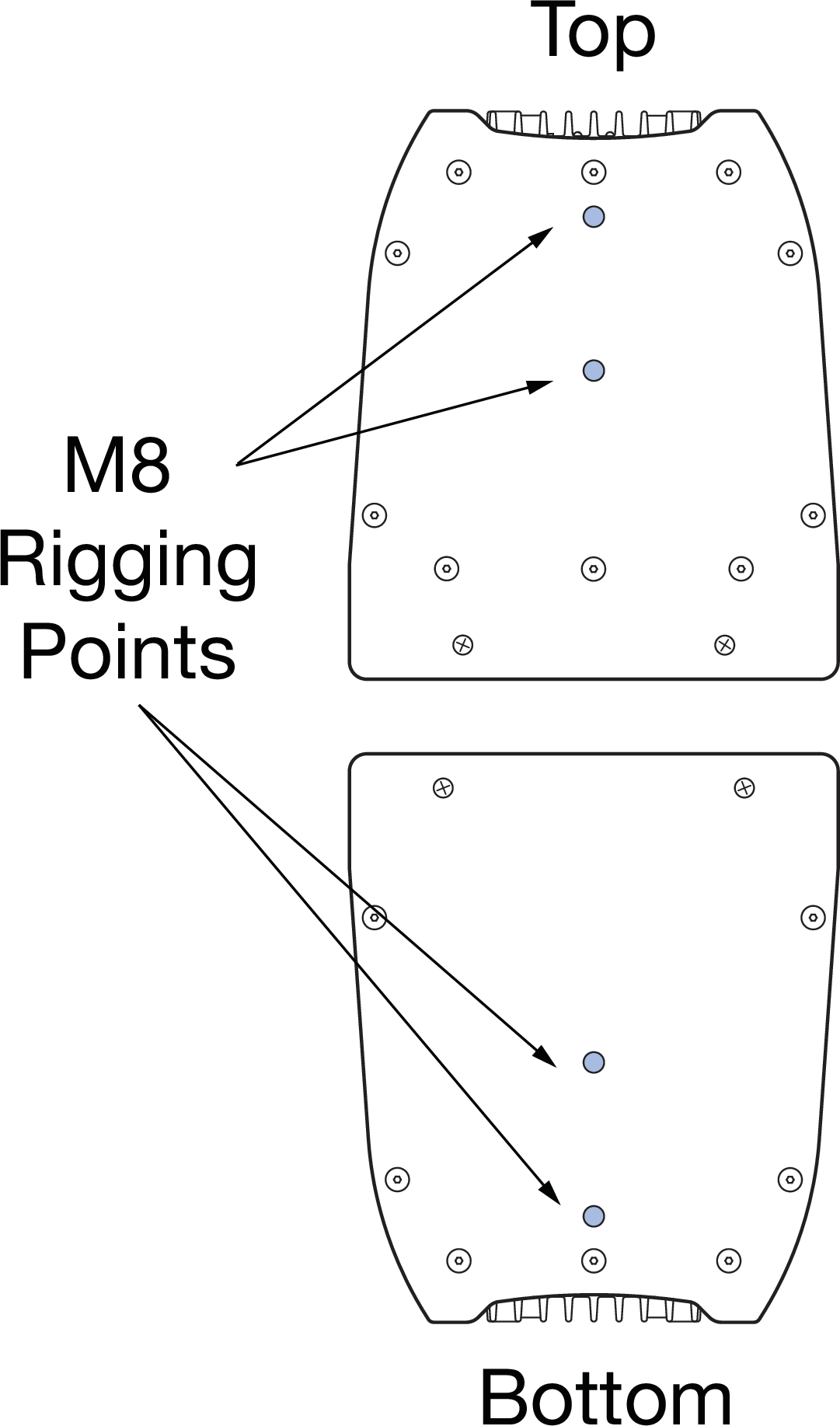
ULTRA-X20XP/22XP/XP Rigging Points
ULTRA-X20XP/22XP/23XP Optional Rigging Accessories
Meyer Sound offers a number of rigging options that facilitate a wide variety of configurations, as described in the table below.
Model | Features |
|---|---|
MPK-POLE Adjustable Pole Mount Kit (PN 40.010.973.01) | Adjustable length 927–1524 mm (36.5–60 in) pole with assisted lift. Lower shaft fits 35 mm cups or use the removable M20 threaded lug for added stability. Upper shaft includes a PAS-M20 Adapter Sleeve to fit loudspeakers with 35 mm and M20 internal pole mounts onto a 35 mm speaker stand and the PAS-M8 Adapter Sleeve to fit loudspeakers with M8 rigging points. (Can also buy the PAS-M20 and PAS-M8 Adapter Sleeves separately). Additional 35 mm to 38 mm (1.5 in) adapter for bottom of pole included. |
PAS-M8 Adapter Sleeve M8 (35 MM Pole) (PN.40.010.975.01) | The PAS-M8 Adapter Sleeve allows the user to connect a 35 mm pole to the ULTRA-X20 M8 rig nuts on the top/bottom of the loudspeaker. |
MYA-X20 Mounting Yoke Kit (PN 40.297.450.01) | The MYA-X20 Yoke suspends a single ULTRA-X20XP/22XP/23XP loudspeaker and supports a wide range of horizontal and vertical adjustments. The yoke attaches to the top and bottom of the loudspeaker using two included M8 bolts/washers. The kit also includes two M8 knobs/washers. The yoke may also be mounted on a 35 mm pole using the optional PAS-M8 Adapter Sleeve to facilitate easy panning and tilting. (An additional M8 nut and washer are required for this application.) |
MUB-X20 U-Bracket Kit (PN 40.297.454.01) | The MUB ULTRA-X20 U-Bracket allows a single ULTRA-X20XP/22XP/23XP loudspeaker to be mounted to a wall (in either vertical or horizontal orientations), to the ceiling or onto the floor. The kit includes two M8 bolts/washers and two M8 knobs/washers. |
MTC-X20 Top Channel Kit (PN 40.297.430.01) | The MTC-X20 Top Channel kit includes a pinnable link in a channel that mounts directly to the top of the ULTRA-X20XP/22XP/23XP rig nuts and supports pick-up of up to two ULTRA-X20XP/22XP/23XP loudspeakers from a single point using the two included lock pins and 3/8-inch shackle. (Mounting two loudspeakers requires three MTC-X20 Top Channel Kits—one on top of the upper loudspeaker and two to connect the lower loudspeaker to the upper.) The kit includes two M8 socket head screws for attaching the channel to the loudspeaker. |
Basic Eye Bolt Rigging
The ULTRA-X20XP loudspeaker can be suspended simply by using one or two M8 eye bolts. The use of two eye bolts provides the added flexibility of aiming and tilting the loudspeaker for targeted coverage.
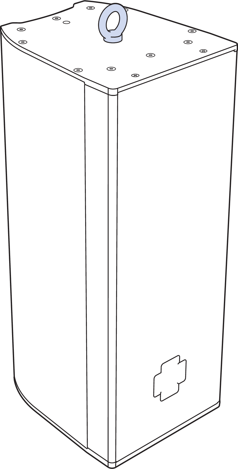
ULTRA-X20XP with One Eye Bolt
Pole-mounting the ULTRA-X20XP
The MPK-POLE-35MM-M20 (PN40.010.973.01) provides an easy and efficient way to mount the ULTRA-X20XP/22XP/23XP on top of a USW-112P, 750-LFC or 900-LFC. The MPK-POLE-35MM-M20 features all steel shafts that telescope from 36.5–60inches and employs a secure knob to hold it in a specific position. The upper shaft includes the removable PAS-M20-35MM with M20 Slug Adapter Sleeve as well as the PAS-M8 Adapter Sleeve.
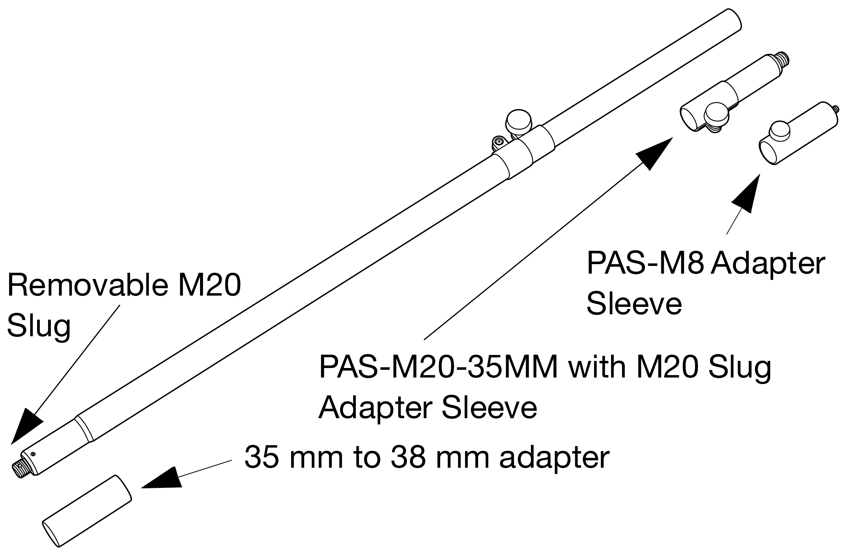
MPK-POLE kit
The MPK-POLE features a lift assist that provides approximately 40 lb of internal gas cylinder pneumatic lift. The lower end of the pole is 35 mm in diameter and has an M20 threaded lug for stability that can be removed if necessary. In addition, the MPK-POLE-35MM-M20 kit includes an adapter for converting the bottom diameter from 35 mm to 38 mm.
Locate the set screws on the Removable M20 Slug side of the pole.
Loosen the set screws using a 2.5 mm hex wrench. Do not loosen so far that the screws fall out of the pole and are lost, as shown in the figure below.
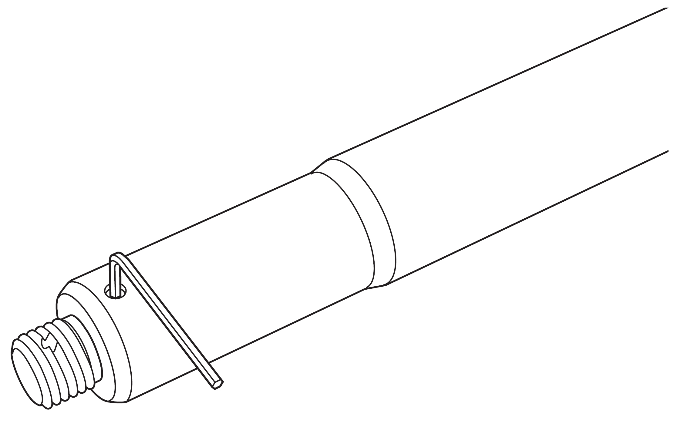
Using Hex Wrench to Loosen M20 Slug Set Screws
Loosen the M20 lug by rotating counter-clockwise (inserting a screwdriver through the lug can help with this process) and remove it, as shown in the figure below.
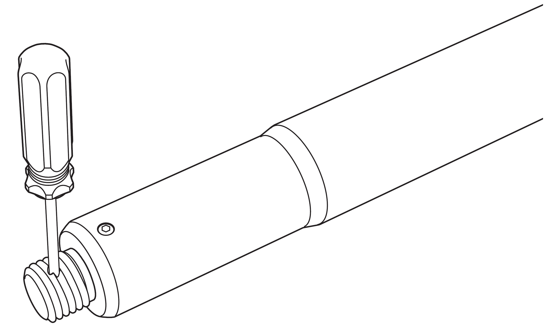
Inserting Screwdriver to Remove M20 Lug
Tighten the set screws enough to ensure they will remain in the pole, as shown in the figure below.
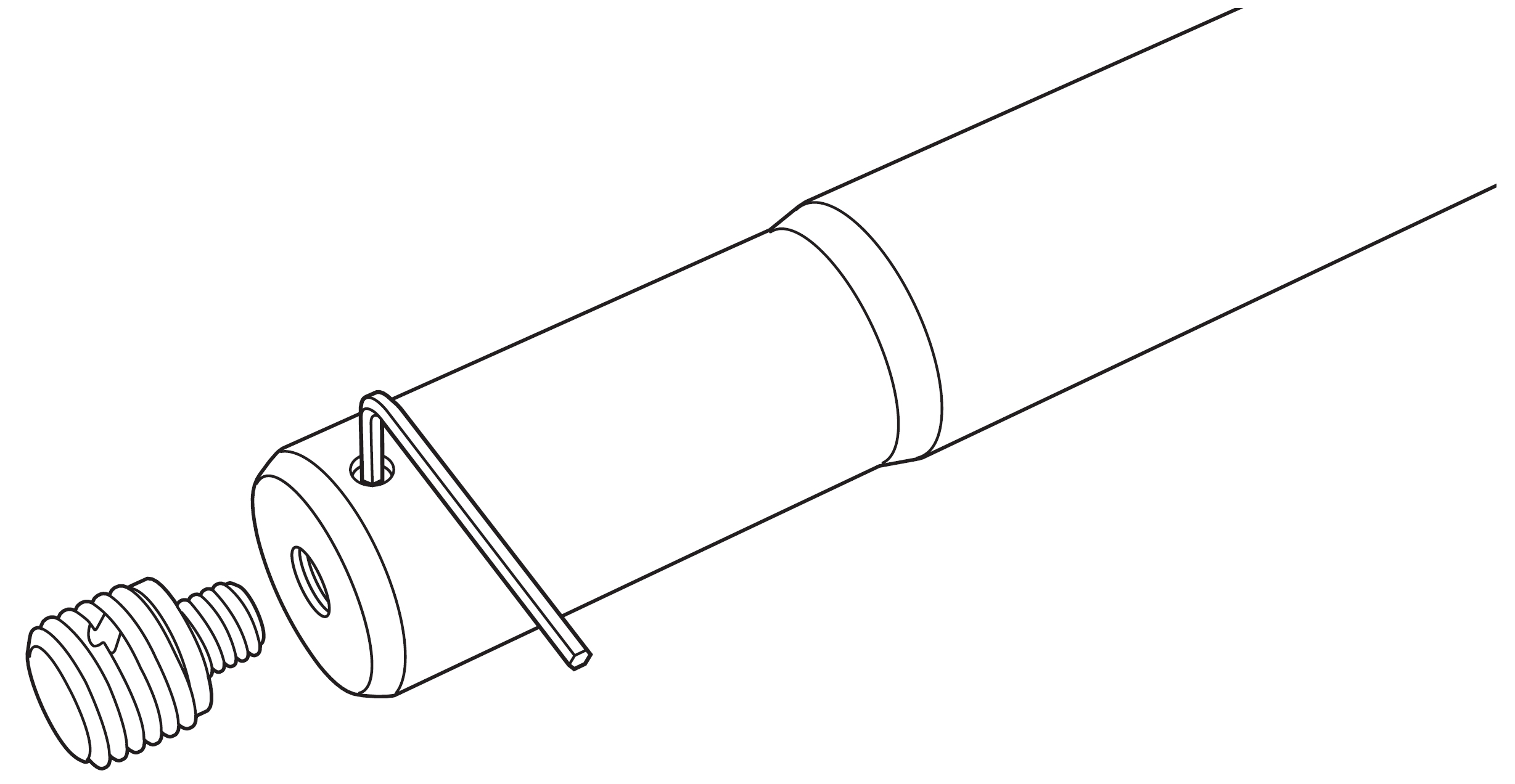
Pole with M20 Slug Removed
The pole can be used without the lug for loudspeakers that have 35 mm cup mounts without M20 threads, or the 35 mm to 38 mm adapter may be slipped onto the bottom for loudspeakers that have 38 mm cups, as shown in the figure below.
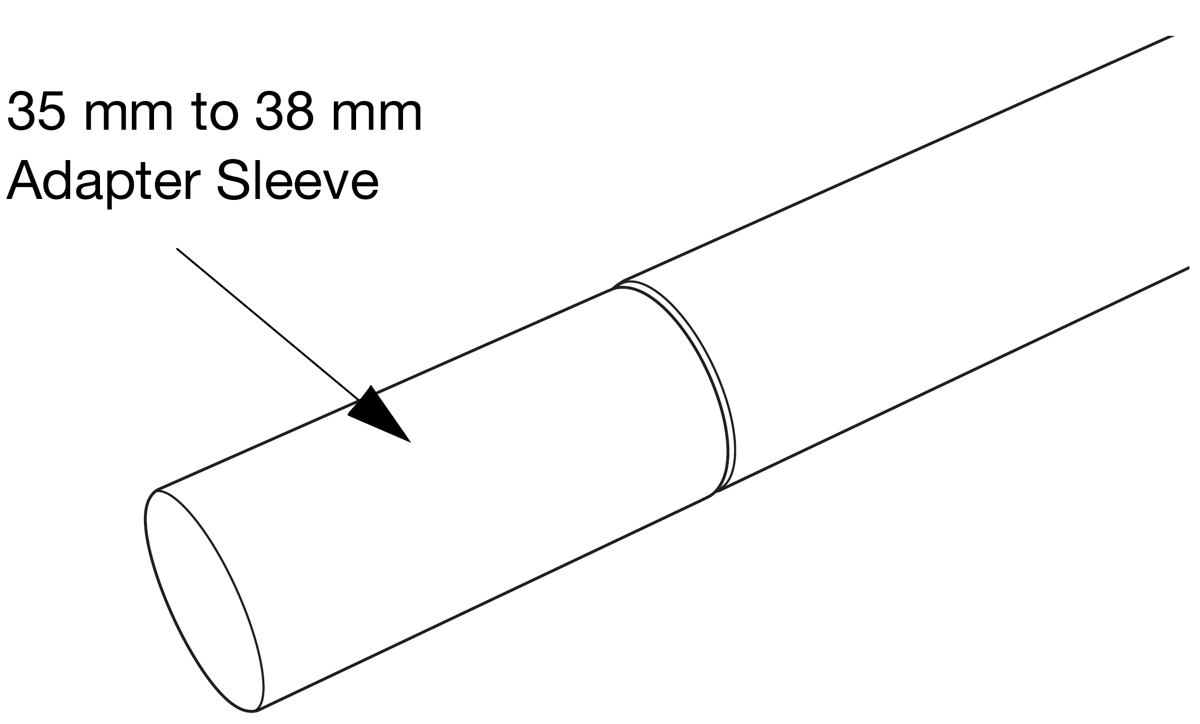
Pole with 35 mm to 38 mm Adapter Sleeve Attached
Meyer Sound recommends that a 750-LFC (or 900-LFC) be upgraded with the 35 mm/M20 internal pole mount cup (PN 40.271.016.02) for a more stable connection, as shown in the figure below. This part is included with the MPK-POLE kit.
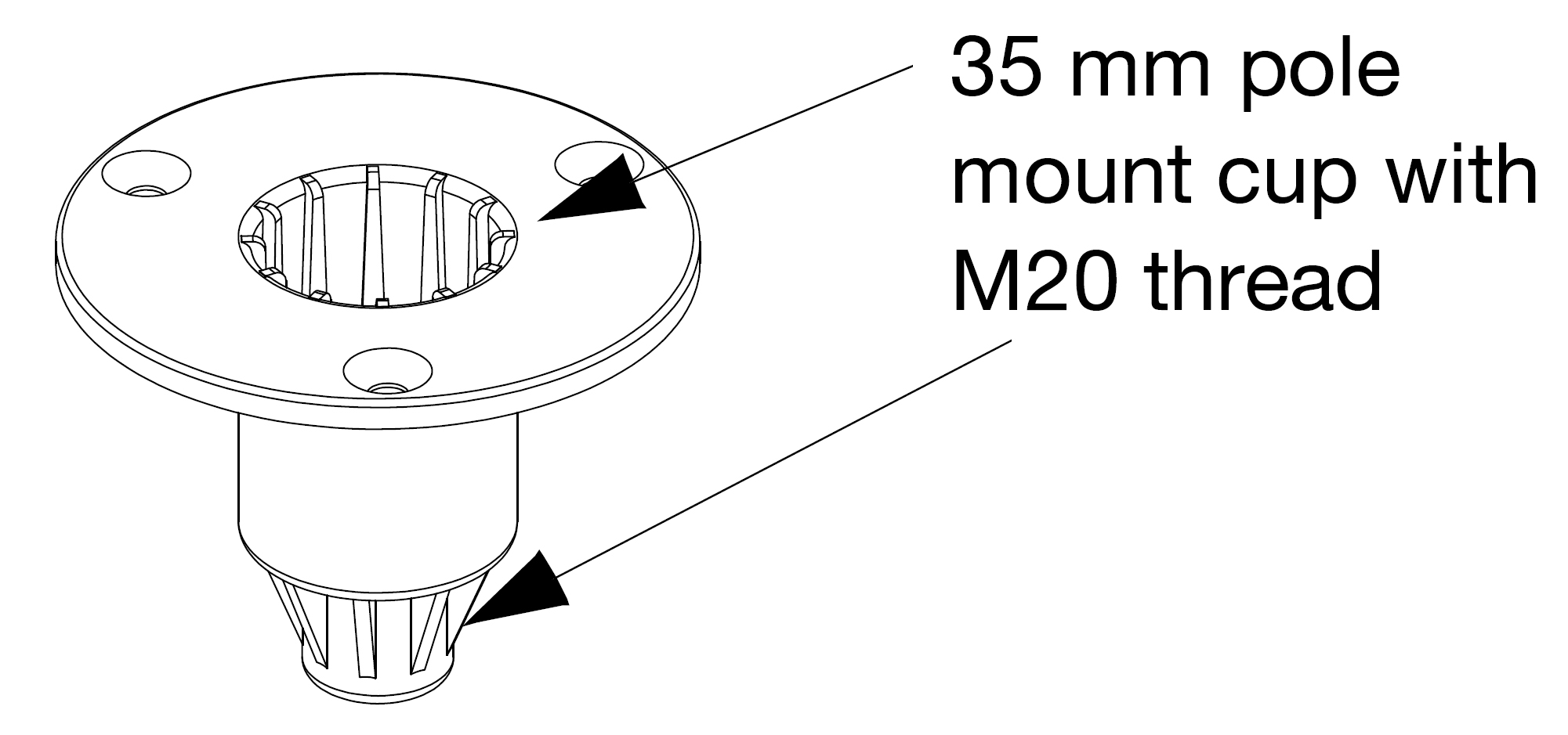
35 mm/M20 Internal Pole Mount Cup (PN 40.271.016.02)
The PAS-M8 Adapter is designed to securely fit into an M8 rig nut on the bottom of the ULTRA-X20XP/22XP/23XP. The separate knob on the adapter tightens it to the pole. (It can also be secured onto any other standard 35 mm pole.)
Tip
Use the PAS-M8 knob to secure the adapter to a pole when packing the pole for travel.
The PAS-M8 may be independently (apart from the pole) threaded into the ULTRA-X20XP/22XP/23XP, as shown in the first figure below, and then the loudspeaker/PAS-M8-35MM Adapter combination mounted onto a pole that is already secured in the subwoofer, as shown in the second figure below. The loudspeaker may be aimed horizontally, and the PAS-M8 knob tightened.
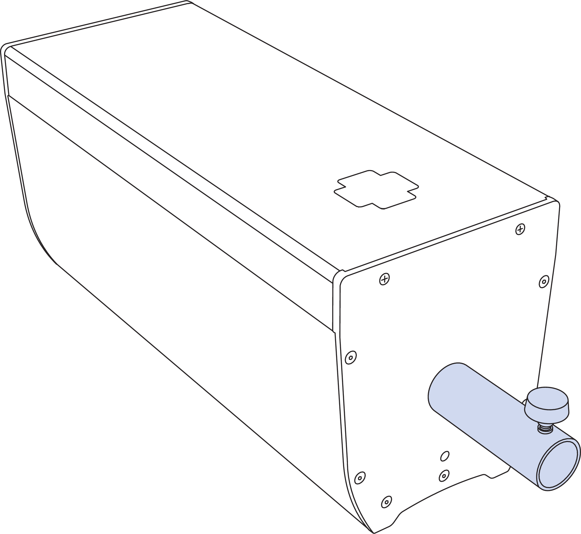
Inserting the PAS-M8 Adapter Sleeve Independently
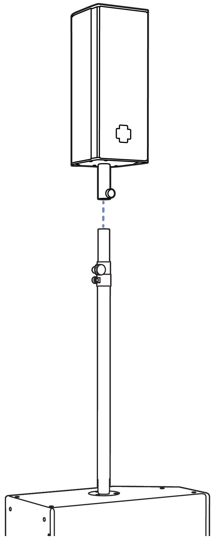
Settling Loudspeaker/Adapter Combination onto Pole
Caution
Due to the small footprint and light weight of the USW-112XP, to keep it stable, avoid extending the pole to the maximum height. Do not lift the ULTRA-X20XP higher than 44 inches from the top of the USW-112P.
When using a third party pole, make sure the pole is designed to support the total weight of the ULTRA-X20XP/22XP/23XP loudspeaker and observe all safety precautions specified by the pole manufacturer
The MYA-X20 Mounting Yoke
The MYA-X20 mounting yoke (PN 40.297.450.01) suspends a single ULTRA-X20XP/22XP/23XP loudspeaker and supports a wide range of horizontal and vertical adjustments. The yoke attaches to the top and bottom of the loudspeaker using the top and bottom center M8 threaded hole, shown in the second figure below. The kit includes two M8 bolts/washers and two M8 knobs/washers. The bolts are recommended for fixed installations. A hanging clamp and steel safety cable (not included) are required to suspend the MYA-X20XP mounting yoke.
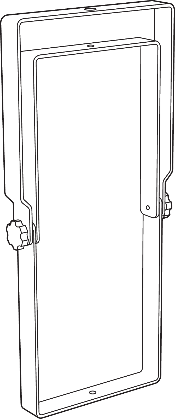
MYA-X20 Mounting Yoke
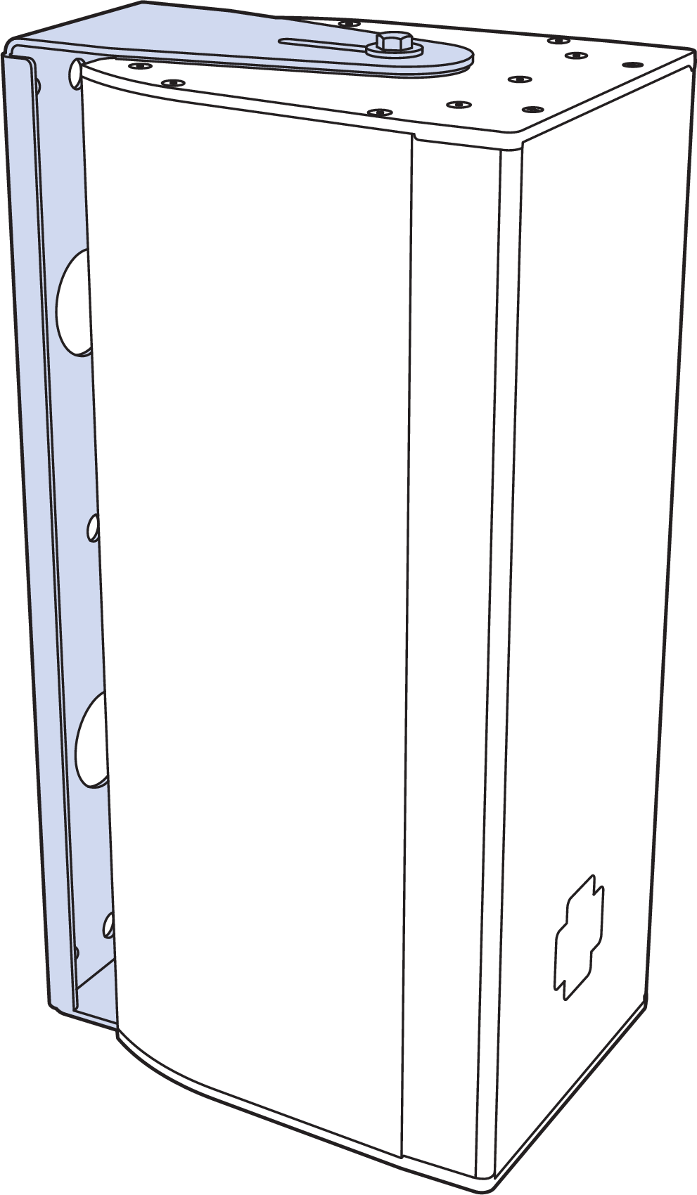
ULTRA-X20XP in the MYA-X20 Yoke Mount
Note
The top bar of MYA-X20 mounting yoke accommodates hanging clamps with standard 1/2-inch or 12 mm bolts.
Caution
THE MYA-X20 Yoke is rated for a single loudspeaker. Never hang a second loudspeaker or other object underneath.
In addition, the yoke may be mounted onto a 35 mm pole using the optional PAS-M8 Adapter Sleeve to facilitate easy panning and tilting.
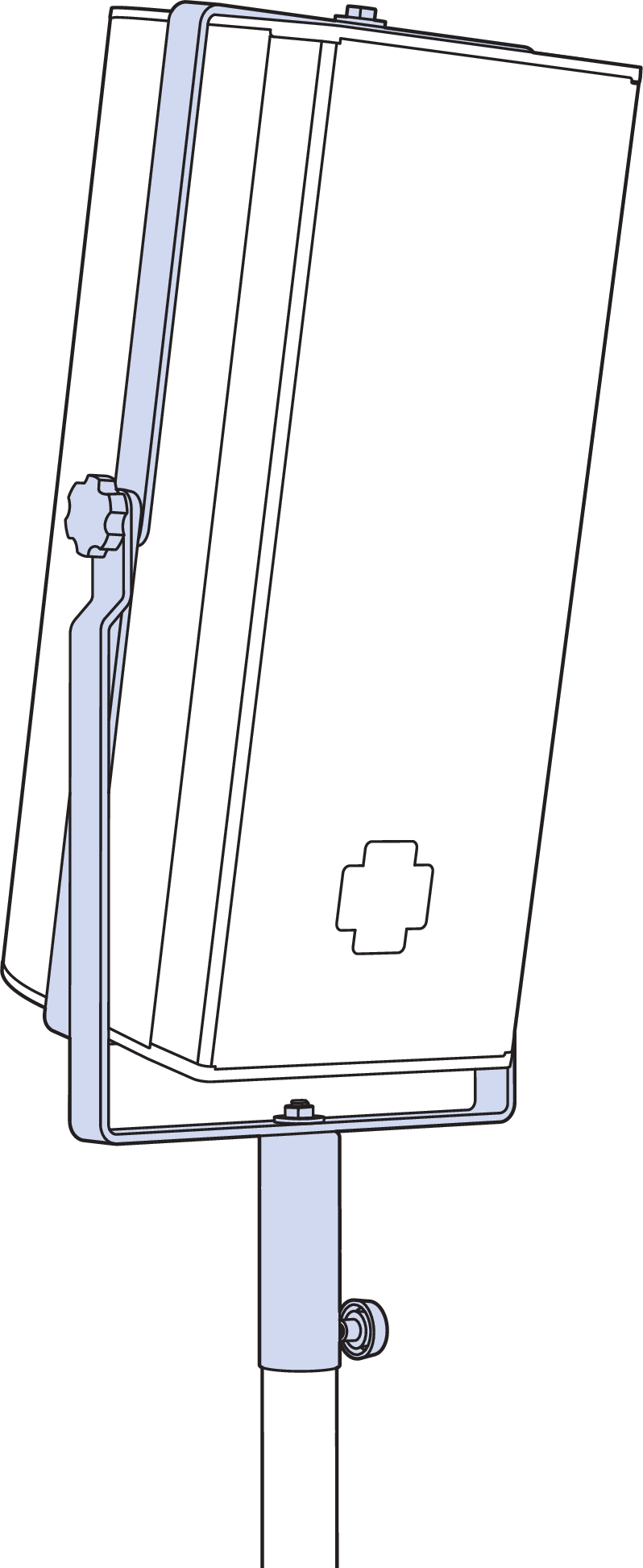
ULTRA-X20XP in the MYA-X20 Yoke Mount on Pole using the optional PAS-M8 Adapter Sleeve (M8 nut required)
MUB-X20 U-Bracket
The MUB-X20 U-Bracket (PN 40.297.454.01) allows a single ULTRA-X20XP/22XP/23XP loudspeaker to be mounted on walls, ceilings, trusses and stage lips. The U-bracket’s adjustment slots allow for adjustment on how close the loudspeaker is located to the mounting surface and at what angle it will be positioned. The MUB-X20 kit includes two M8 bolts with washers and two M8 knobs with washers. The bolts are recommended for fixed installations.
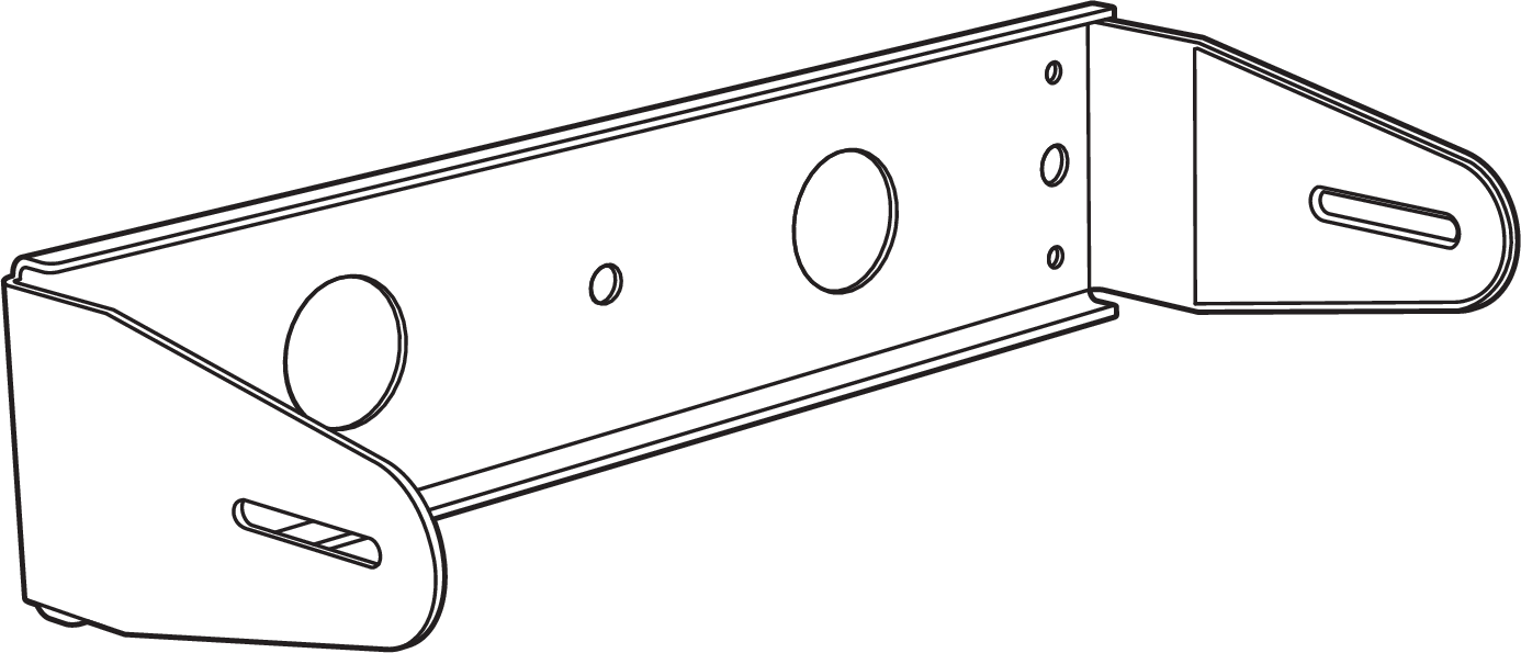
MUB-X20 U-Bracket
One ULTRA-X20XP can be safely be mounted with the MUB-X20 U-bracket at a 5:1 safety factor. When mounting an ULTRA-X20XP with the MUB-X20 U-bracket, the U-bracket must be secured to the mounting surface with one of the configurations indicated in the table below.
Hole Location | Safety Factor |
|---|---|
1/2-inch center hole | 5:1 |
Two 1/2-inch outer holes | 5:1 |
All four 1/4-inch corner holes | 5:1 |
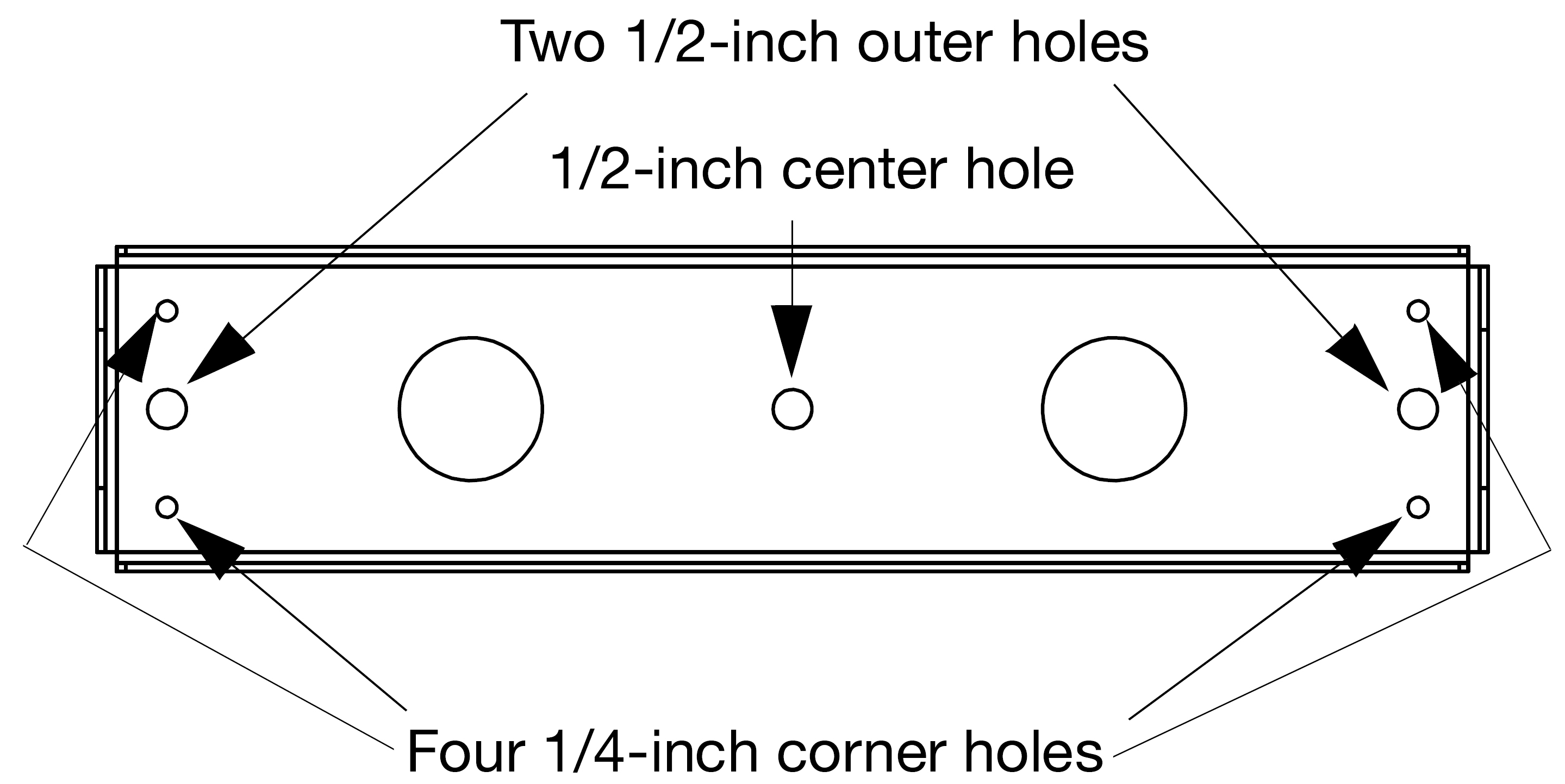
MUB-X20 Mounting Holes
Wall-Mounting with the MUB-X20
The ULTRA-X20XP may be mounted either horizontally or vertically with the MUB-X20.
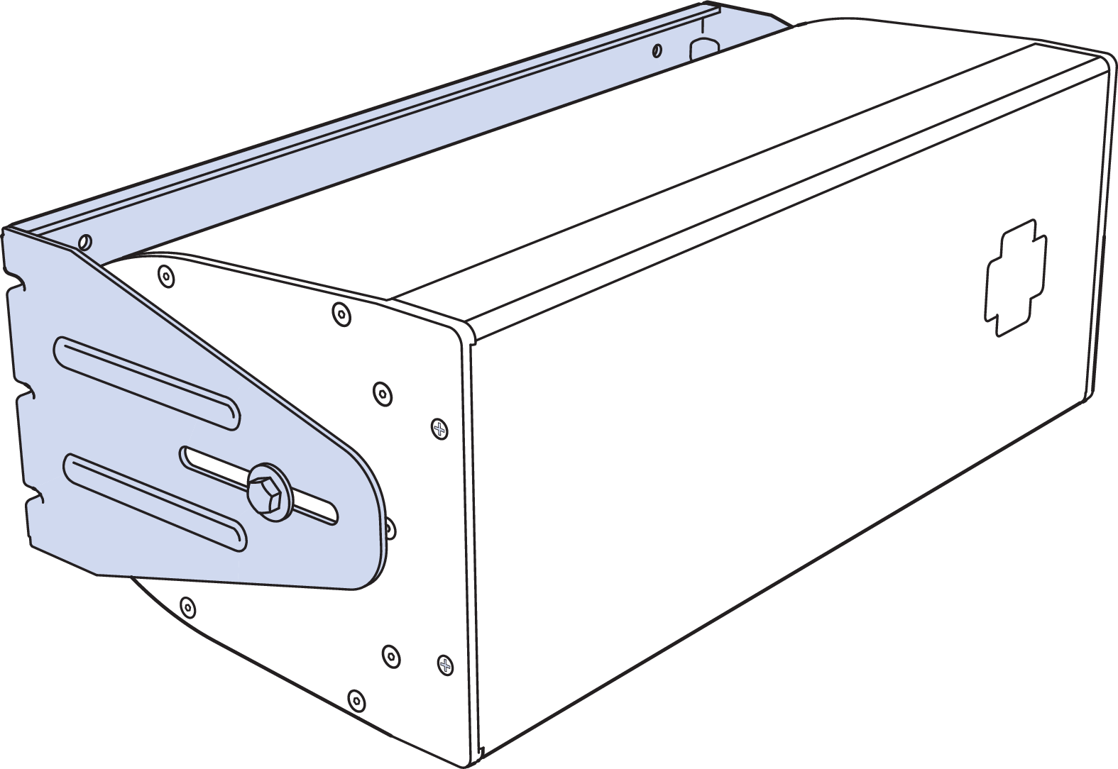
ULTRA-X20XP with MUB-X20 for Wall Mount, Horizontal

ULTRA-X20XP with MUB-X20 for Wall Mount, Vertical
Ceiling-Mounting with the MUB-X20
The ULTRA-X20XP can be mounted on a ceiling, underbalcony, or canopy area with the MUB-X20 U-bracket.
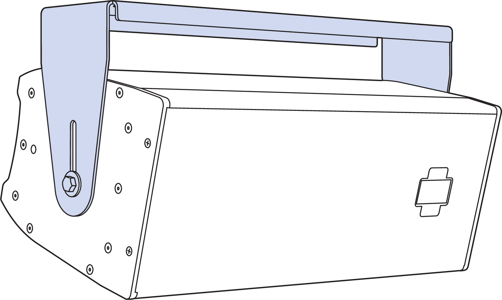
ULTRA-X20XP with MUB-X20, Ceiling Mount
Truss-Mounting with the MUB-X20
The 0.55-inch holes in the MUB-X20 support mounting an ULTRA-X20XP on a truss using two “C” or “G” hanging clamps (not included in kit).
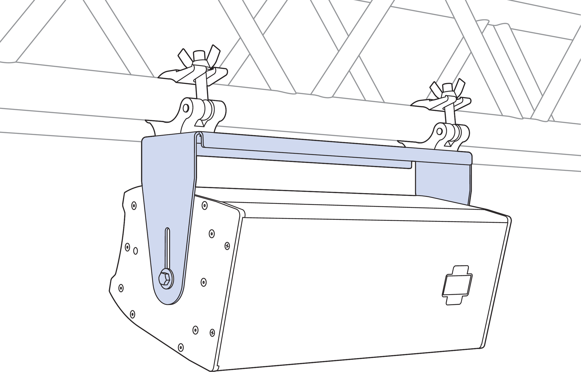
ULTRA-X20XP Truss-Mounted using MUB-X20
Floor-mounting with the MUB-X20
The ULTRA-X20XP can be mounted to the floor or on a stage lip (for front-fill applications) with the MUB-X20 U-bracket.
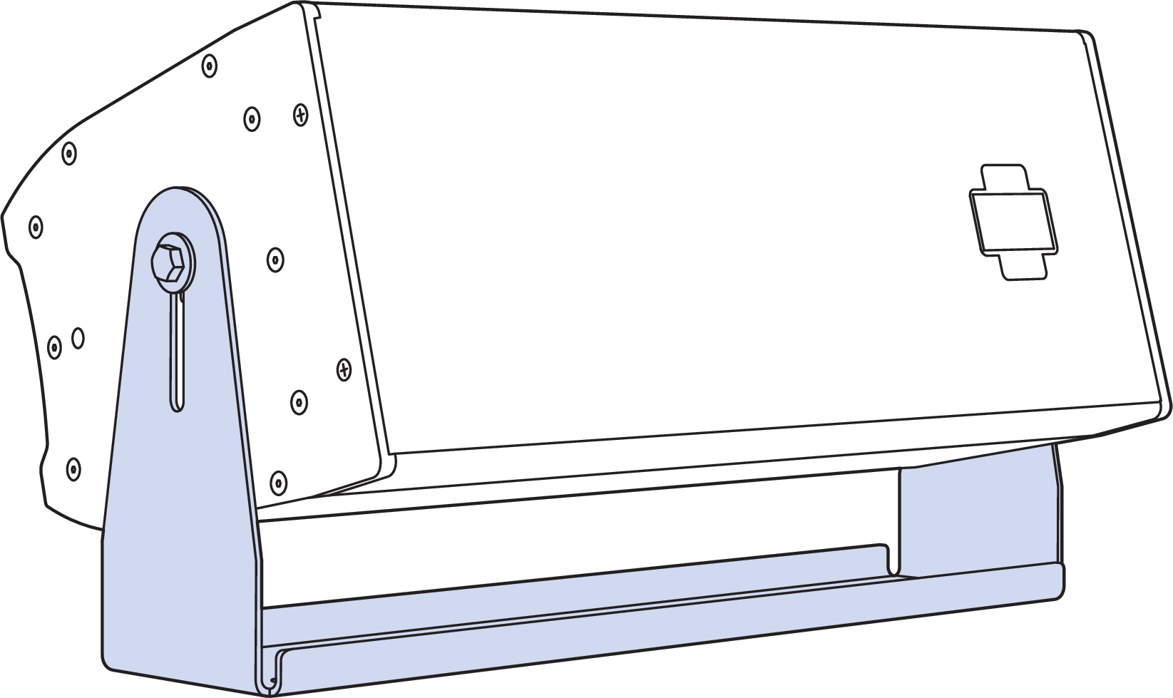
ULTRA-X20XP with MUB-X20, Ceiling Mount
MTC-X20 Top Channel Kit
The MTC-X20 Top Channel kit (PN 40.297.430.01) includes a pinnable link in a channel that mounts directly to the ULTRA-X20XP/22XP/23XP rig nuts. It supports pick-up of two ULTRA-X20XP/22XP/23XP loudspeakers from a single point using the two included lock pins and 3/8-inch black shackle. The MTC-X20 Top Channel attaches to the speaker with two M8 bolts.
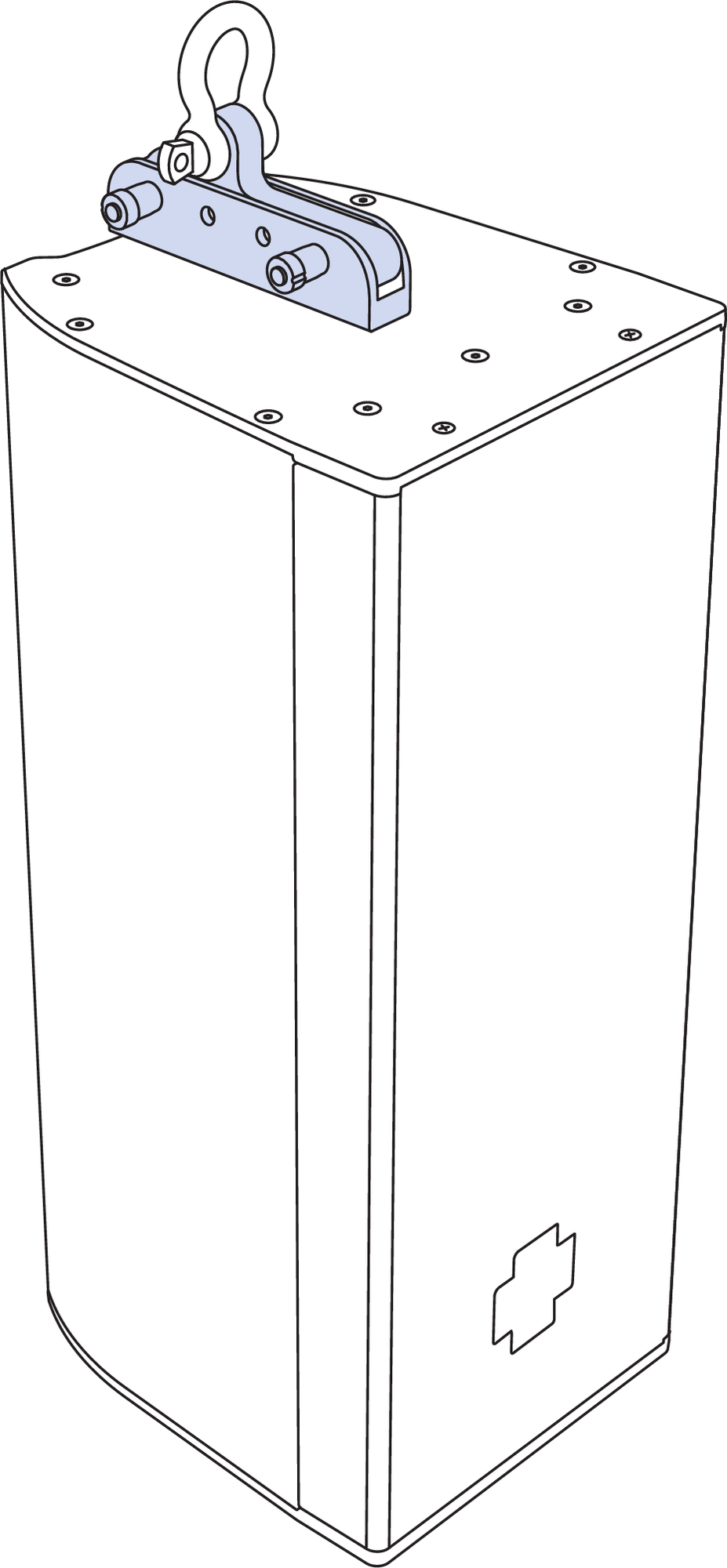
MTC-X20 Top Channel Kit Installed at Top of Cabinet
The versatile configuration of the channel and link, with the ability to slide the pinnable link within the channel, facilitates 13 different top pickup points. This flexibility allows for approximately +11° to –22° tilting of a loudspeaker that hangs from a single point, as described in the table below.

MTC-X20 Pickup Points
Using three versions of this kit allows the user to create a two-loudspeaker configuration with an angle of 50° between top and bottom speakers, as shown in the figure below.
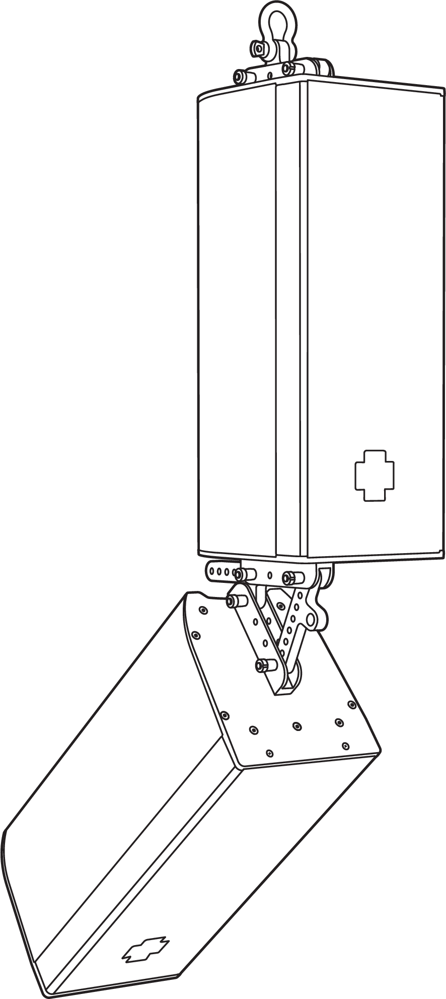
Two MTC-X20 Top Channels linking speakers at a 50° angle with a third MTC-X20 channel on top for pickup point.
MTC-X20 Pin Positions and Resultant Angle Tilt for Single Point Hang
Degree Tilt | Speaker Side View | MTC-X20 Hole Position | Alternate Hole Position |
|---|---|---|---|
22° Downtilt | 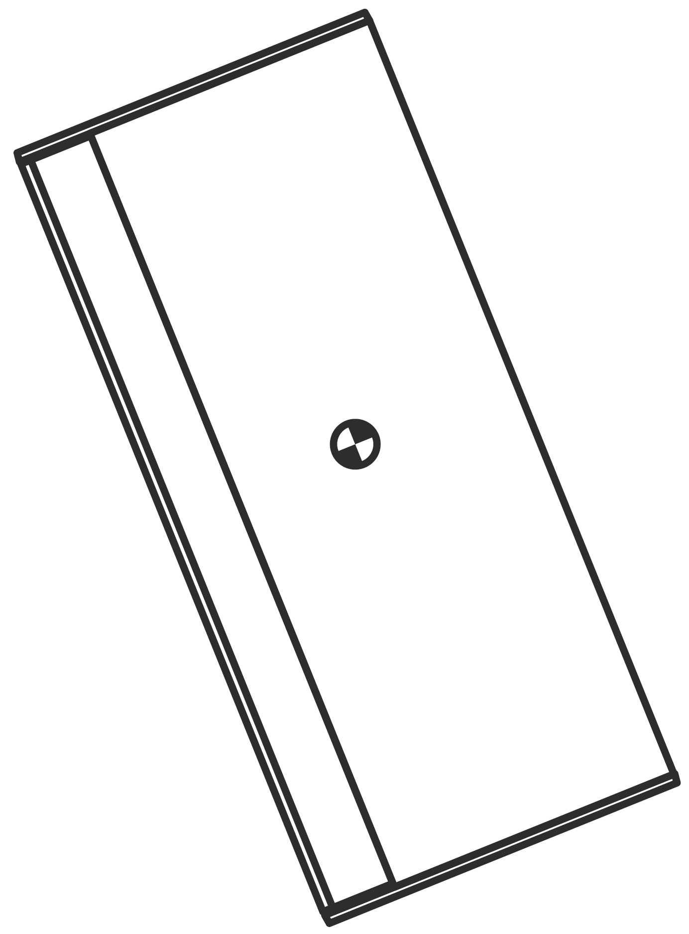 | ||
20° Downtilt | 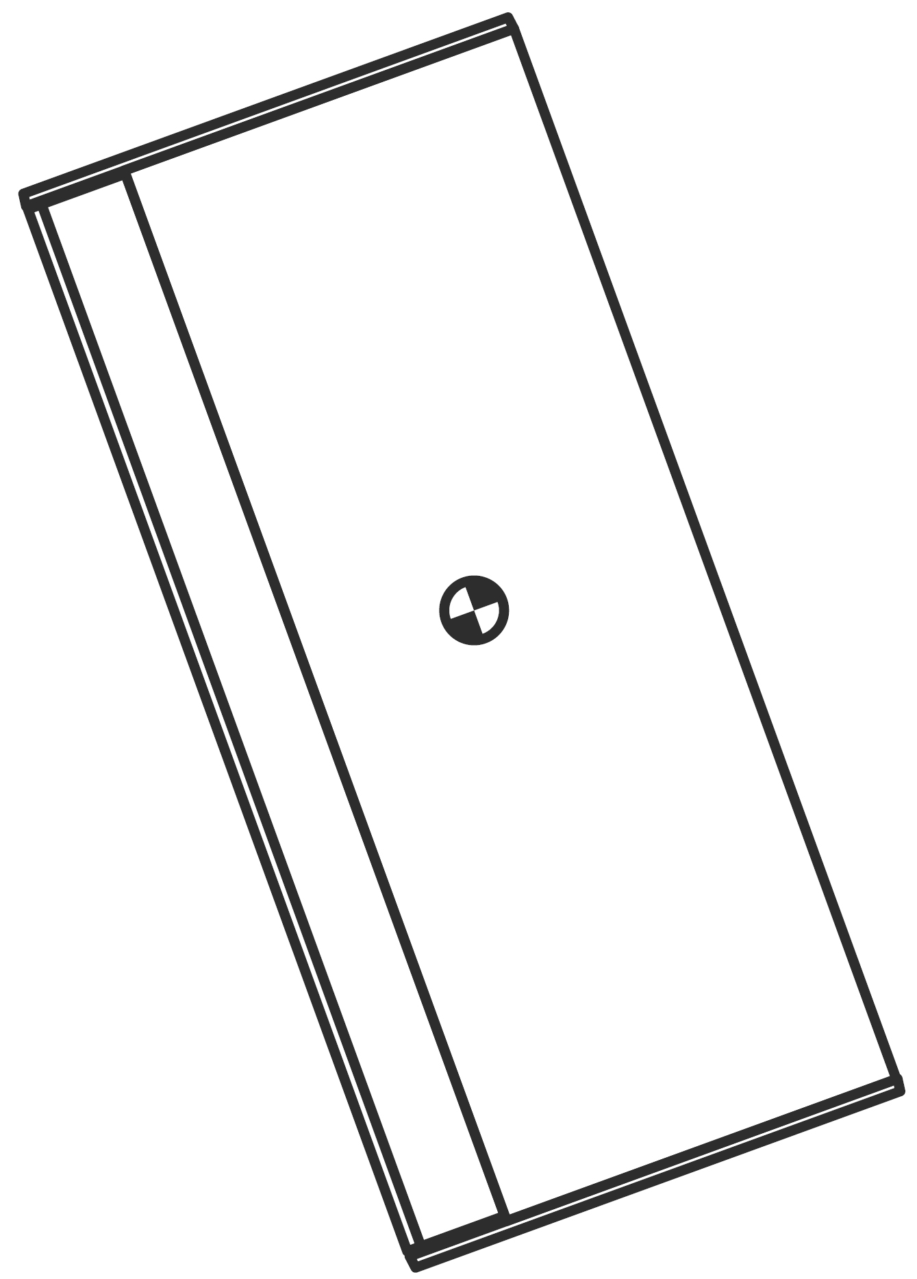 | ||
17° Downtilt | 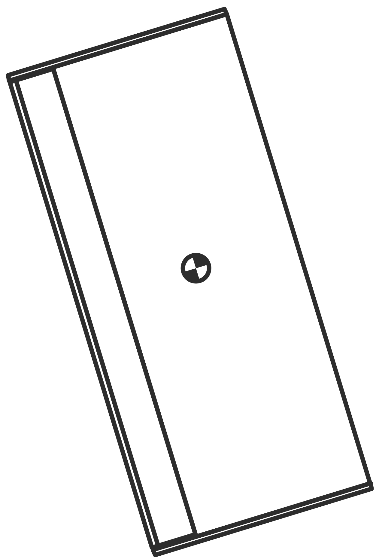 | ||
14° Downtilt | 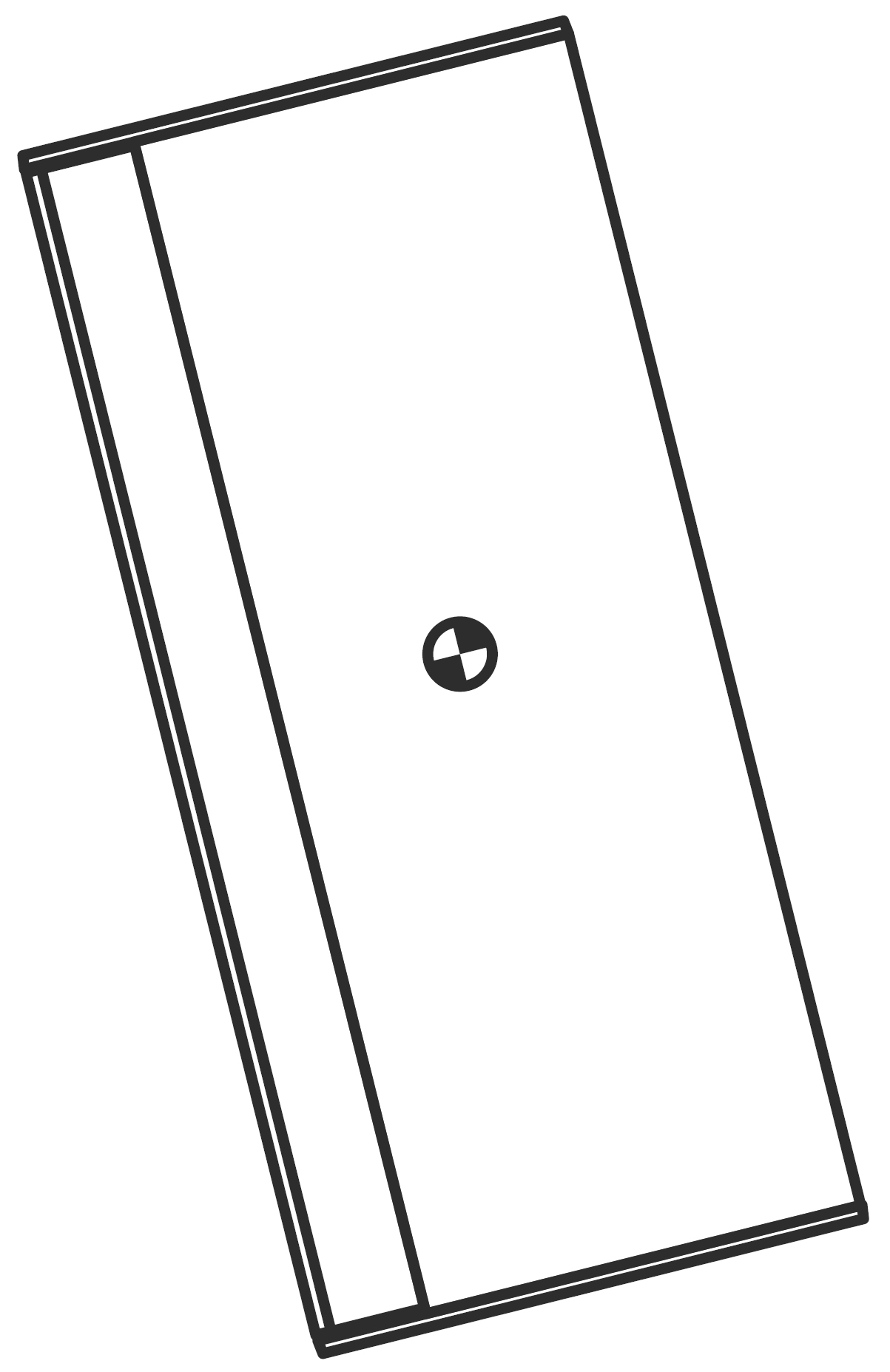 | ||
12° Downtilt | 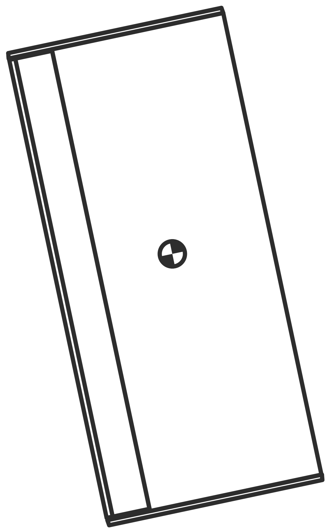 | ||
9° Downtilt | 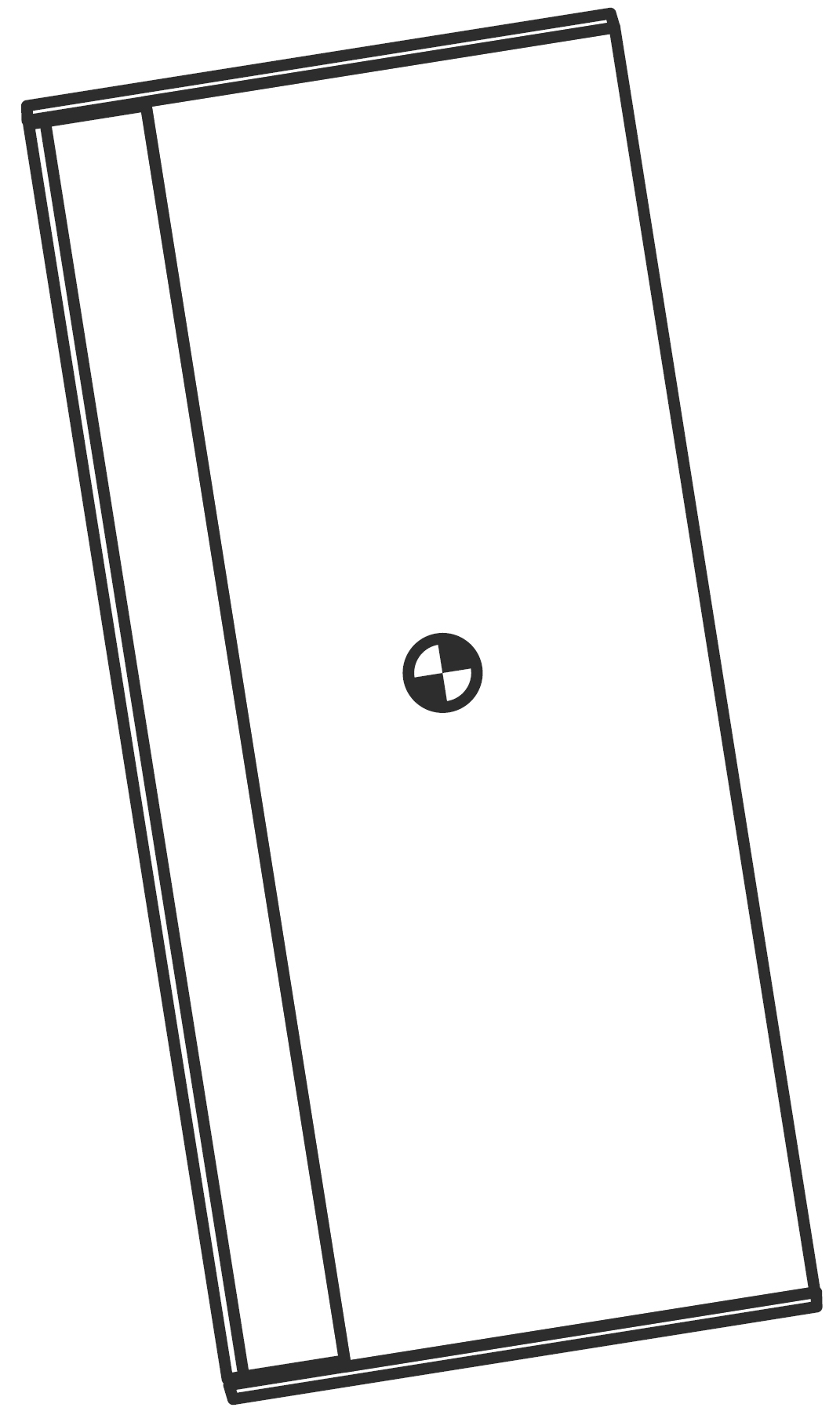 | ||
6° Downtilt | 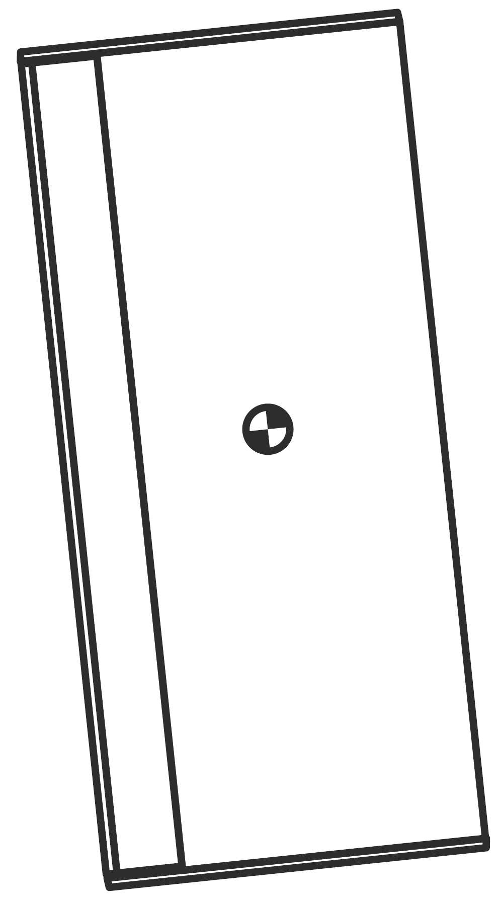 | ||
3° Downtilt | 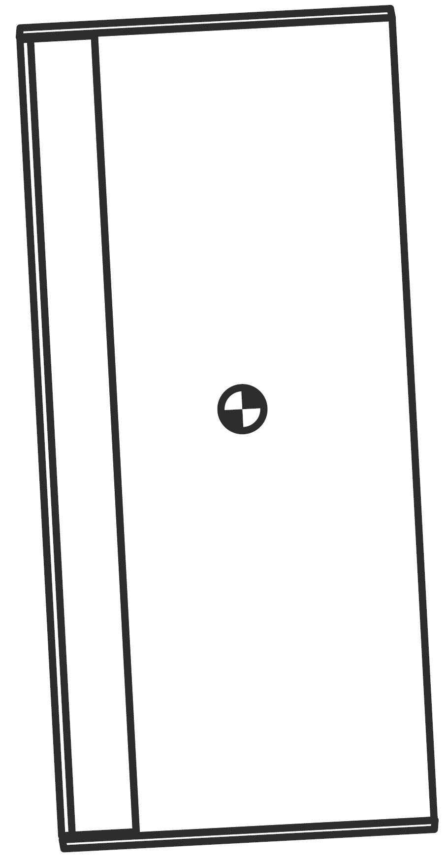 | ||
0° | 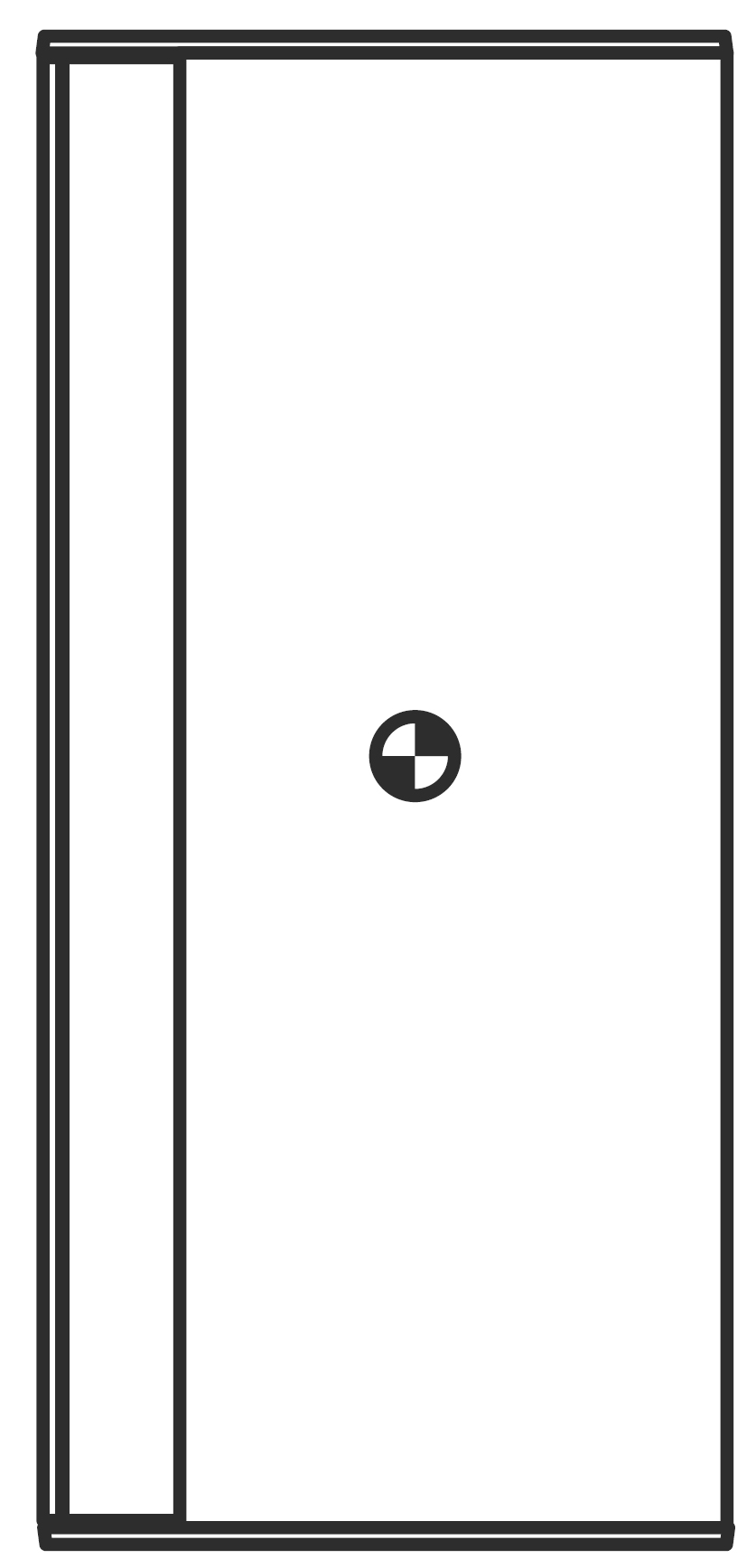 | ||
3° Uptilt |  | ||
5° Uptilt | 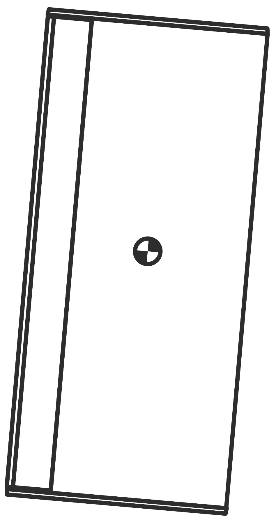 | ||
8° Uptilt | 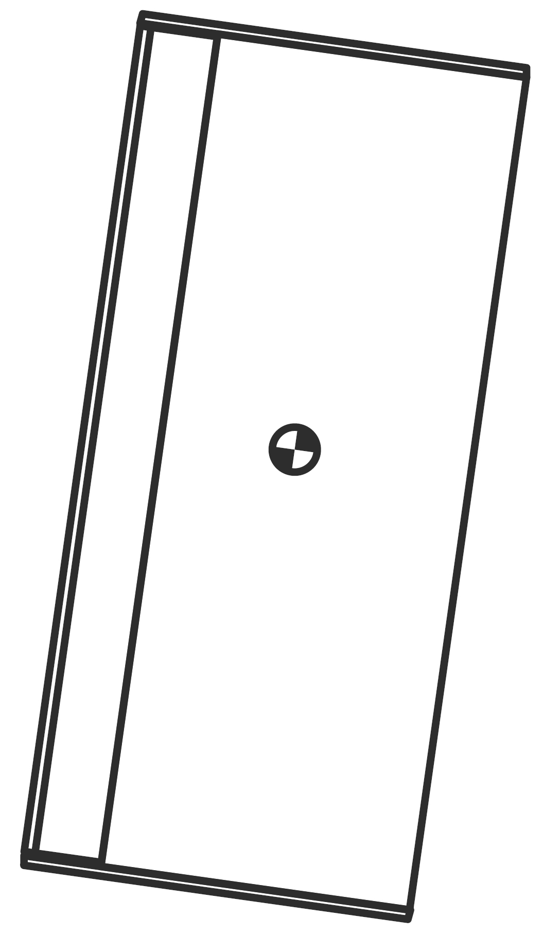 | ||
11° Uptilt | 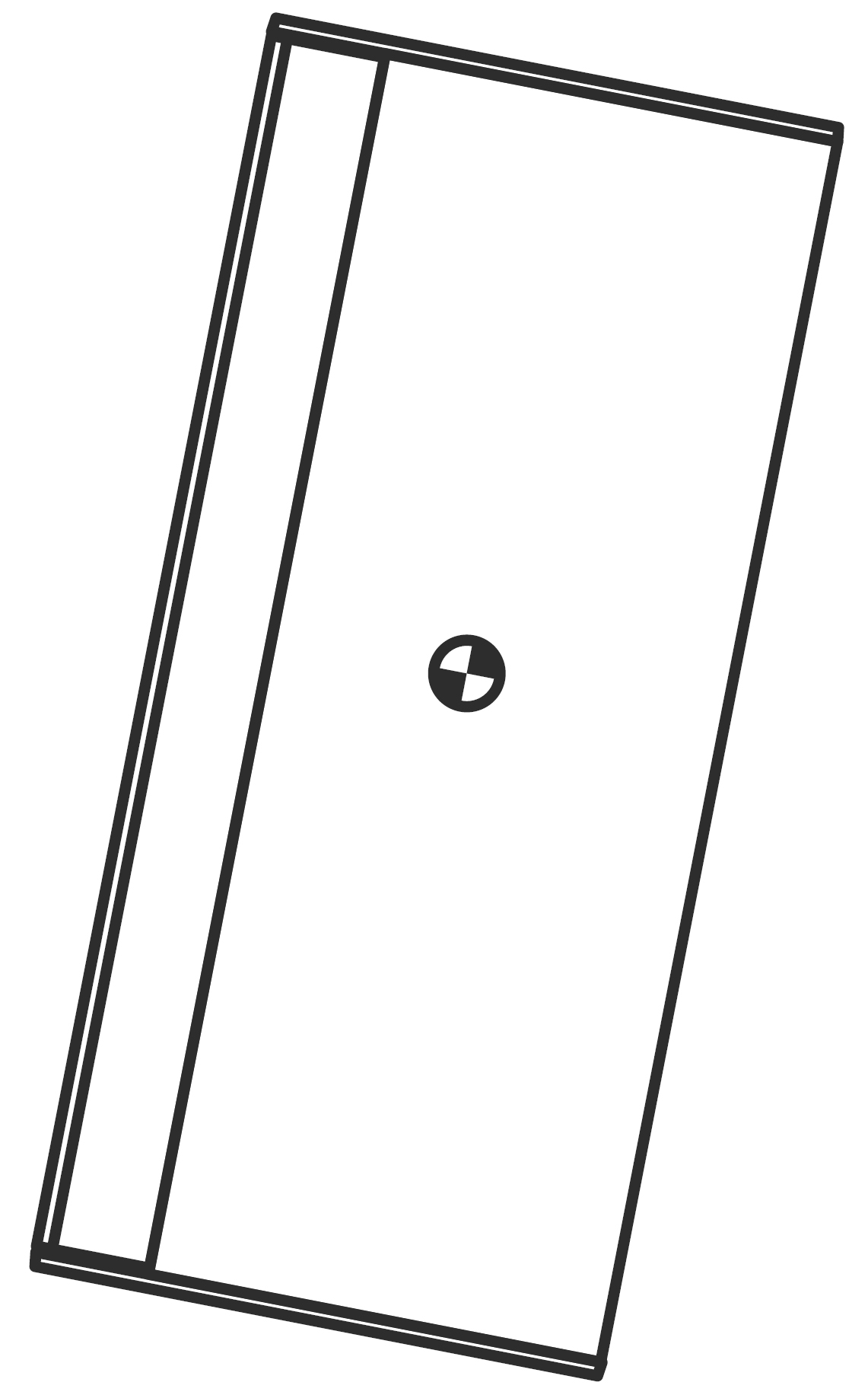 |
Mounting the ULTRA-X20XP/22XP/23XP under the ULTRA-X40/42
It is possible to mount an ULTRA-X20XP/22XP/23XP beneath an ULTRA-X40/42 using one MTC-X40 and one MTC-X20. Four configurations are possible, as shown in the figure below.
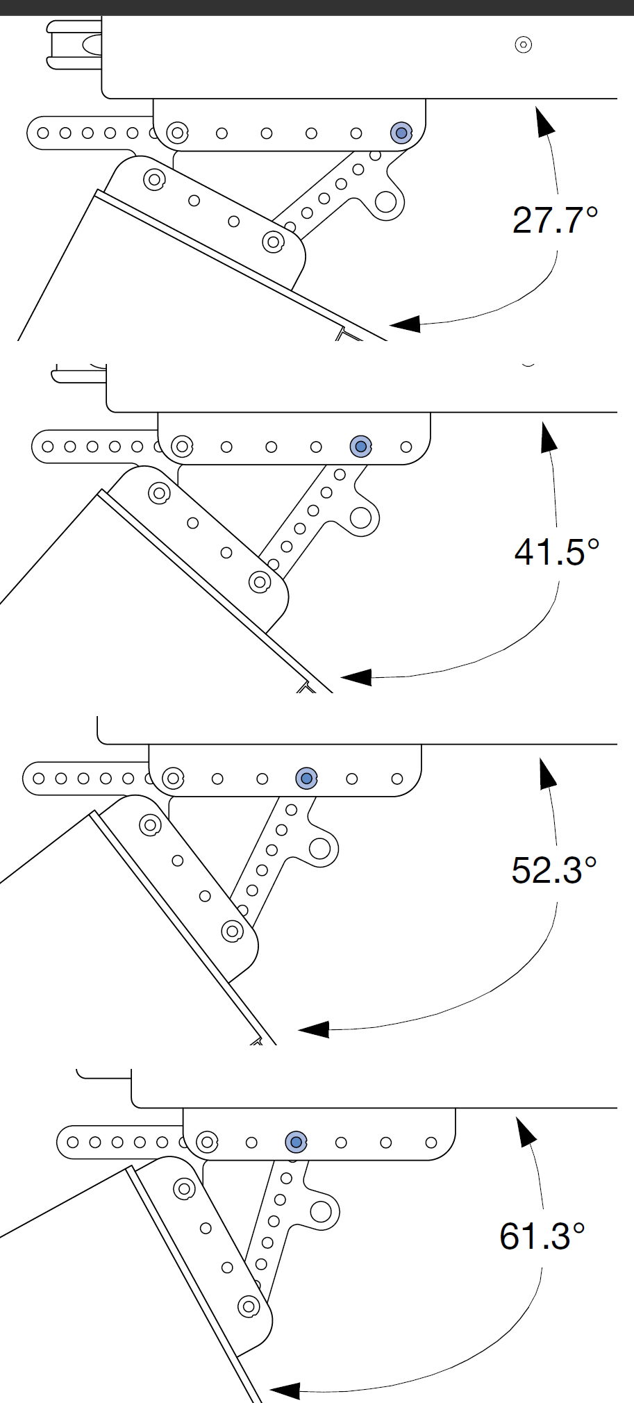
Allowed Mounting Positions for ULTRA-X20 Beneath ULTRA-X40 using one MTC-X40 and one MTC-X20
Using the Heat Sink Mounting Holes
The ULTRA-X20XP/22XP/23XP heat sink on the rear of the loudspeaker also has four M6 x 1-inch mounting holes. These four mounting holes may be used with third-party wall mounts to hang a single loudspeaker.
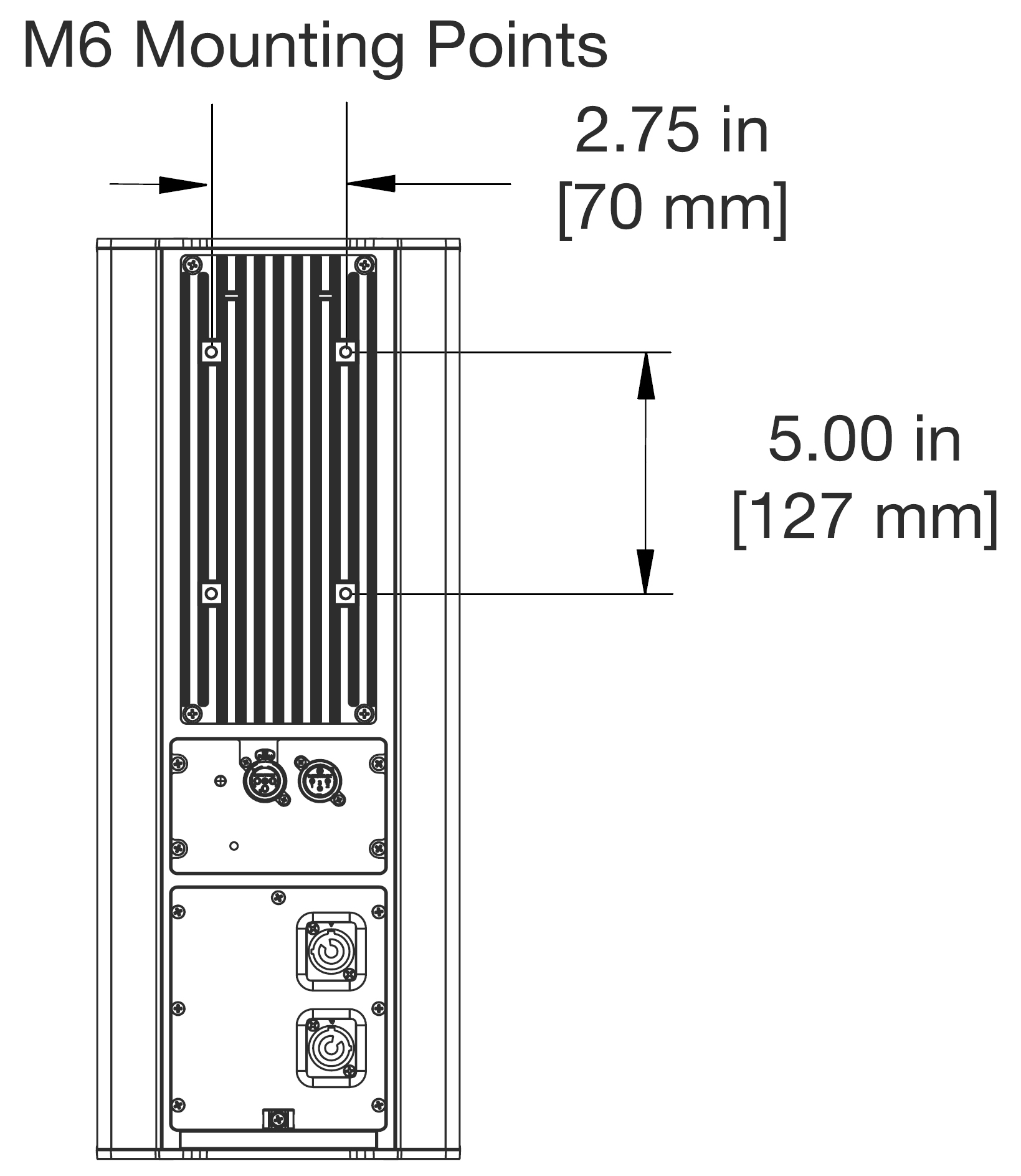
Dimensions for Spacing of Heat Sink Mounting Holes
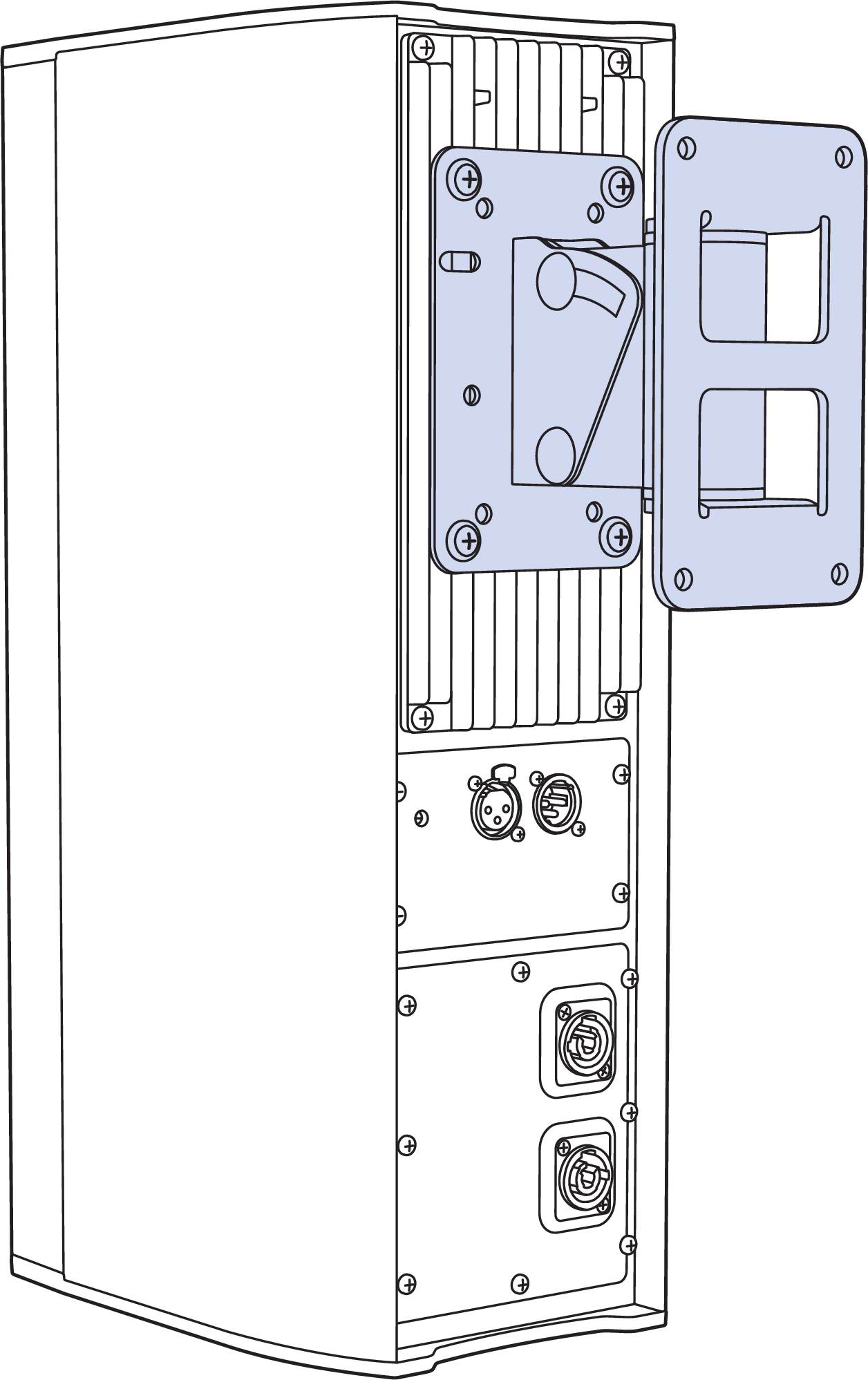
Using the Heat Sink Mounting Holes with Example ThirdParty Bracket
System Design and Integration Tools
MAPP System Design Tool
The MAPP System Design Tool is a powerful, cross-platform application for accurately predicting the coverage pattern, frequency response, phase response, impulse response, and SPL capability of individual or arrayed Meyer Sound loudspeakers.

MAPP System Design Tool
Whether planning for fixed installations or for tours with multiple venues, use MAPP to accurately predict the appropriate loudspeaker deployment for each job, complete with coverage data, system delay and equalization settings, rigging information, and detailed design illustrations. MAPP’s accurate, high-resolution predictions ensure that systems will perform as intended, thereby eliminating unexpected coverage problems and minimizing onsite adjustments.
The key to the accuracy of MAPP’s predictions is MeyerSound’s exhaustive database of loudspeaker measurements. Performance predictions for each loudspeaker are based on 3-dimensional, 65,000+ 1/48th-octave-band measurements taken in the MeyerSound anechoic chamber. The extraordinary consistency between Meyer Sound loudspeakers guarantees that predictions from MAPP will closely match their actual performance.
MAPP software allows for configuration of MeyerSound loudspeaker systems and definition of the environment in which they operate, including air temperature, pressure, humidity, and the location of prediction surfaces. Importing both CAD (.DXF) and Sketchup (.SKP) files containing detailed venue information to act as an anchor model to the prediction surfaces and a visual aid to facilitate prediction data interpretation is also possible.
Tip
See meyersound.com for support and more information about MAPP.
MAPP Capabilities
With MAPP, you can:
Simulate different loudspeaker configurations to refine system designs and determine the best coverage for intended audience areas
Model loudspeaker interactions to locate constructive and destructive interferences so that loudspeakers can be re-aimed and repositioned as necessary
Place microphones anywhere in the Model View space and predict loudspeaker frequency response, phase response, and sound pressure levels at each microphone position
Determine delay settings for fill loudspeakers using the Inverse Fast Fourier Transform and phase response feature
Preview the results of signal processing to determine optimum settings for the best system response
Automatically calculate load information for arrays to determine necessary minimum rigging capacity, front-to-back weight distribution, and center of gravity location
Generate and export system images and system PDF reports for client presentations
Synchronize GALAXY processor output channel settings in real-time with virtual or real GALAXY units, allowing in-the-field changes to be predicted during system alignments
Galileo GALAXY Network Platform
The Galileo GALAXY Network Platform is a sophisticated loudspeaker management tool for controlling all MeyerSound speaker types. The GALAXY loudspeaker processor extends a high level of audio control in driving and aligning loudspeaker systems with multiple zones. It provides a powerful tool set for corrective equalization (EQ) and creative fine-tuning for a full range of applications from touring to cinema.
Users can readily program the GALAXY processor using Compass software running on a host computer or via the Compass Go application for the iPad. Connecting MAPP to the GALAXY processor will also allow the user to push output channel settings created in MAPP as a starting point. Compass Control Software includes custom-designed settings for each family of speakers, as well as to integrate families together. For example, the Product Integration feature matches the phase characteristics between Meyer speaker families to ensure the most coherent summation.
Processing tools for inputs and outputs include delay, parametric EQ and U-Shaping EQ. Output processing also includes polarity reversal, Low-Mid Beam Control (LMBC), atmospheric correction, and All Pass filters.
The built-in summing and delay matrices allow a user to easily assign gain and delay values, respectively, at each cross point. This capability greatly facilitates using one loudspeaker to satisfy multiple purposes.
Front panel controls let a user intuitively and quickly operate a GALAXY processor without a computer during live use.
The GALAXY 408, GALAXY 816 and GALAXY 816-AES3 processor versions have the same audio processing capability with different I/O. See www.meyersound.com to locate their datasheets for more information.
Meyer Sound Weather Protection
The Weather Protection option from Meyer Sound is intended to increase the useful life of Meyer Sound loudspeakers when they are installed outdoors and exposed to different and often harsh weather conditions. Our Weather Protection includes a penetrating treatment to raw wood, use of special primers, and plating on all steel parts used (or alternatively, the use of stainless steel hardware). Weather Protection is designed to prevent malfunctions caused by harsh operating environments and slows the accelerated wear and tear that occurs in outdoor environments.
When Is Weather Protection Advisable?
Weather Protection is strongly recommended for all permanent outdoor installations where loudspeakers are directly exposed to the elements. This includes desert and semi-arid climates, where protection against dust and sand is important, and where infrequent rainstorms can contribute to deterioration of loudspeaker components.
Weather Protection is also recommended when the loudspeakers are sheltered from direct exposure to precipitation but are nevertheless exposed to prolonged high humidity, fog or mist. Examples would be installations on covered outdoor terraces or pavilions
Weather Protection is further advisable for portable or touring systems when any significant outdoor use is anticipated. Even though standard procedures may call for using external protective measures, these are often not implemented in time to prevent moisture intrusions that could lead to premature performance degradation of the loudspeaker.
Climate Variation and Owner Maintenance
The wear and tear on a loudspeaker will vary significantly with different climatic conditions. For example, a weather protected loudspeaker installed in a sunlight-exposed location on an ocean pier will experience much harsher conditions than a loudspeaker in a similar installation that is shaded by trees and exposed only to rainfall. The constant exposure to direct UV radiation and salt air environment will cause a loudspeaker to wear more quickly than one with partial UV shielding and exposed only to freshwater moisture.
Wear can eventually affect the performance of the loudspeaker. It also affects aesthetics. For example, in salt air environments, the exterior grille can quickly show signs of oxidation, causing unsightly discoloration.
Apart from selecting suitable weather protection, the progress of wear and tear on the loudspeaker can be slowed by a regular schedule of inspection and cleaning. This maintenance is particularly necessary in harsh environments. Inspection and cleaning should include routine removal of any visible oxidation or environmental particulates, as these can accelerate metal corrosion or decay of the cabinet. If installed loudspeakers are not in use for an extended period, exterior protection or temporary removal and storage of the loudspeakers should be considered.
Benefits of Weather Protection
There are several benefits to selecting the Meyer Sound Weather Protection option:
Functionality - Weather Protection prolongs the service life of the loudspeaker by preventing premature degradation of internal components.
Safety - Weather Protection lessens the chance of electrical malfunctions or structural failures.
Warning
IT IS THE RESPONSIBILITY OF PURCHASERS/USERS/OPERATORS TO SELECT WEATHER PROTECTION WHEN APPROPRIATE FOR THEIR USE AND TO PERIODICALLY INSPECT THEIR LOUDSPEAKER INSTALLATIONS FOR ANY DETERIORATION THAT MAY LEAD TO SAFETY CONCERNS.
Aesthetics - Weather Protection slows wear and tear on the exterior of the loudspeaker in harsh conditions. Early signs of wear and tear on the exterior of the loudspeaker indicate over-exposure to the elements.
Standards Compliance - Weather Protection helps in meeting IP ratings for loudspeakers. IP ratings are an internationally recognized standard often used in installations involving our products. A further explanation of IP ratings is given in the IP Ratings.
Weather Protection Components
Standard Weather Protection
Meyer Sound designs toward an IP rating of IPX4 (see IP Ratings) for Standard Weather Protection, which includes the following components:
Wood treatment — Prior to cabinet manufacturing, the raw wood receives a special treatment that penetrates and stabilizes the wood fibers to withstand a wide range of temperatures and exposure to extreme humidity.
Cabinet finishing — The assembled cabinets receive a highly impervious finish that includes a sealing primer and a finishing topcoat. The coatings are applied on both surfaces, with one coat on the interior and two on the exterior. The final step is a two-part modified acrylic urethane similar to that used in military applications.
Driver treatment — All cone drivers are coated with a water-resistant sealant.
Exterior protection — Grille frames are coated to resist corrosion, and all components that mount to the cabinet use custom gaskets and stainless steel fasteners.
Removable rain hood — The rain hood is designed to shield connectors even in wind-driven rain.
Ultra Weather Protection
For installations in extremely harsh environments, Meyer Sound offers an Ultra Weather Protection option on a limited number of loudspeaker models. (For a list of products offered with this option, please contact Meyer Sound.) Meyer Sound designs toward an IP rating of IPX5 for Ultra Weather Protection, which includes all of the components of standard Weather Protection, plus the following:
Extended cabinet finishing with extra thick proprietary coatings
Special printed circuit board treatments
Use of corrosion-resistant hardware
Ultra Weather Protection is recommended for applications where loudspeakers will experience exposure to a salt air environment or chemicals, that have no sheltering from corrosive spray or UV exposure, and that cannot be covered or removed during their service life. Examples would include cruise ship exterior areas, ocean-side visitor attractions, swimming pool areas, and themed attractions with wind-carried water spray.
Installation Practices
Meyer Sound assumes normal and accepted installation practices are used when installing Meyer Sound Loudspeakers outdoors. Deviation from such practices may cause weather protection to be ineffective and void the warranty for the loudspeaker.
Examples of unacceptable and acceptable installation practices include:
Loudspeakers installed outdoors should not face upward.
Loudspeakers with a rain hood should be installed in such a way that the rain hood opening is not facing any direction but down.
Meyer Sound-supplied rigging components should not be modified (for example, by drilling additional holes in a MUB for mounting to a wall). When an installer/integrator modifies a Meyer Sound-supplied rigging component to support their installation method, it is considered compromised and out of warranty.
All loudspeaker cabling must be installed with a "drip-loop" or equivalent method to ensure that rain/ water is NOT wicked toward the loudspeaker.
If in doubt about an installation method, contact Meyer Sound Technical Support for assistance.
Always discuss the environmental conditions of your Meyer Sound installation with your Sales Manager, and verify the availability of Weather Protection for your selected loudspeaker models. The Sales Manager, together with Technical Support, will verify the appropriate level of weather protection for the loudspeakers and related rigging hardware.
IP Ratings
IP stands for "Ingress Protection." The current format for expressing an IP rating is a 2-digit code. The first digit of an IP rating represents protection from solid objects. The second digit of an IP rating represents protection from water or moisture. The table below provides a chart of IP ratings and the corresponding definitions of the rating.
Note
IP ratings only apply to the "ENCLOSURE." A loudspeaker is considered an enclosure and as such we can apply an IP rating to it. Rigging hardware is not an enclosure and therefore IP ratings do not apply. Also, cable and cable-mount connectors used to connect to the loudspeaker are NOT part of the enclosure and therefore not part of the IP rating. Only the chassis-mounted part of the connector is considered part of the enclosure.
First Digit (Protection against solid objects) | Definition | Second Digit (Protection against liquids) | Definition |
|---|---|---|---|
X | Characteristic numeral is not required to be specified. | X | Characteristic numeral is not required to be specified. |
0 | No protection | 0 | No protection |
1 | Protected against solid objects over 50mm. | 1 | Protected against vertically falling drops of water. |
2 | Protected against solid objects over 12 mm. | 2 | Protected against direct sprays up to 15° from the vertical. |
3 | Protected against solid objects over 2.5mm. | 3 | Protected against direct sprays up to 60° from the vertical |
4 | Protected against solid objects over 1 mm. | 4 | Protected against direct sprays from all directions. Limited ingress permitted |
5 | Protected against dust. Limited ingress permitted. | 5 | Protected against low-pressure jets of water from all directions. Limited ingress permitted. |
6 | Totally protected against dust. | 6 | Protected against strong jets of water from all directions. Limited ingress permitted. |
7 | Protected against the effect of temporary immersion between 15cm and 1m. | ||
8 | Protected against the effect of long-term submersion of 1m or more. |
Rain Hood
A sealed, weather-protected version of the ULTRA-X20XP/22XP/23XP is available with an included rain hood kit that safeguards the Phoenix connectors from the elements in fixed outdoor installations. The rain hood is made of durable, high- impact, black polycarbonate, as shown in the figures below. The weather-protected ULTRA-X20XP/22XP/23XP can be mounted vertically or horizontally. (For restrictions, see Permissible Orientations.)
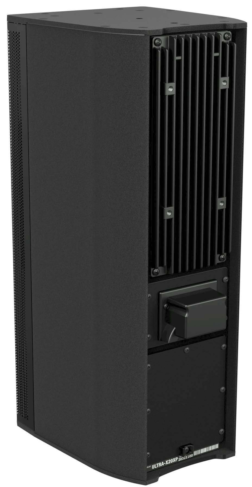
Weather-Protected ULTRA-X20XP with Rain Hood Attached
Note
Weather-protected ULTRA-X20XP/ 22XP/23XP loudspeakers using the rain hood are rated IPX4 for water intrusion.
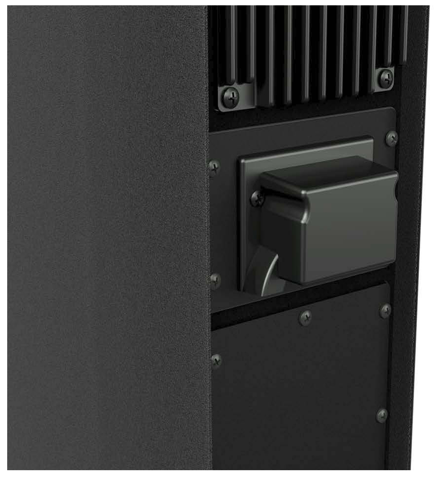
Close-up view of ULTRA-X20XP with Rain Hood
Rain Hood Installation
Attach the audio/power source Phoenix cable connector to the loudspeaker (not shown).
Secure the rain hood to the user panel with the two 6-32 x 0.38-inch pan head screws provided, as shown in the first figure below. The recommended torque value for rain hood screws is 8 in-lbs (0.9 N·m).
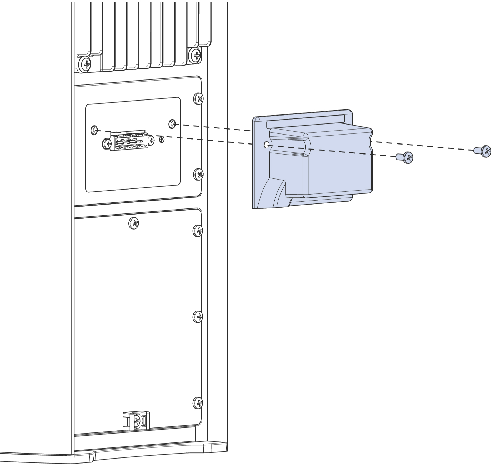
ULTRA-X20XP with Rain Hood Assembly
Note
The rain hood comes with the gasket attached.
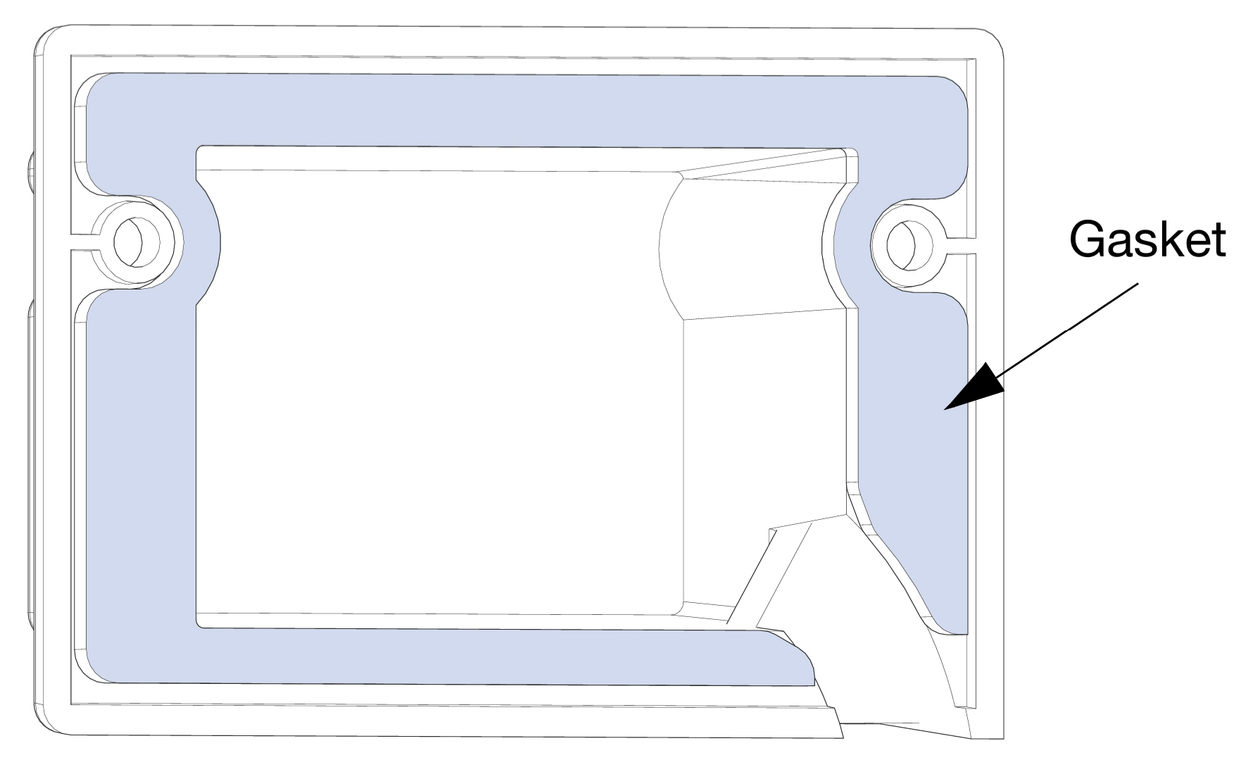
Rain Hood with Gasket Attached
Permissible Orientations
Caution
When mounting the loudspeaker, ensure that the cables will exit from the bottom of the loudspeaker when the rain hood is installed. There is only one permissible vertical orientation, as shown in the first figure below, and one permissible horizontal orientation, as shown in the second figure below).
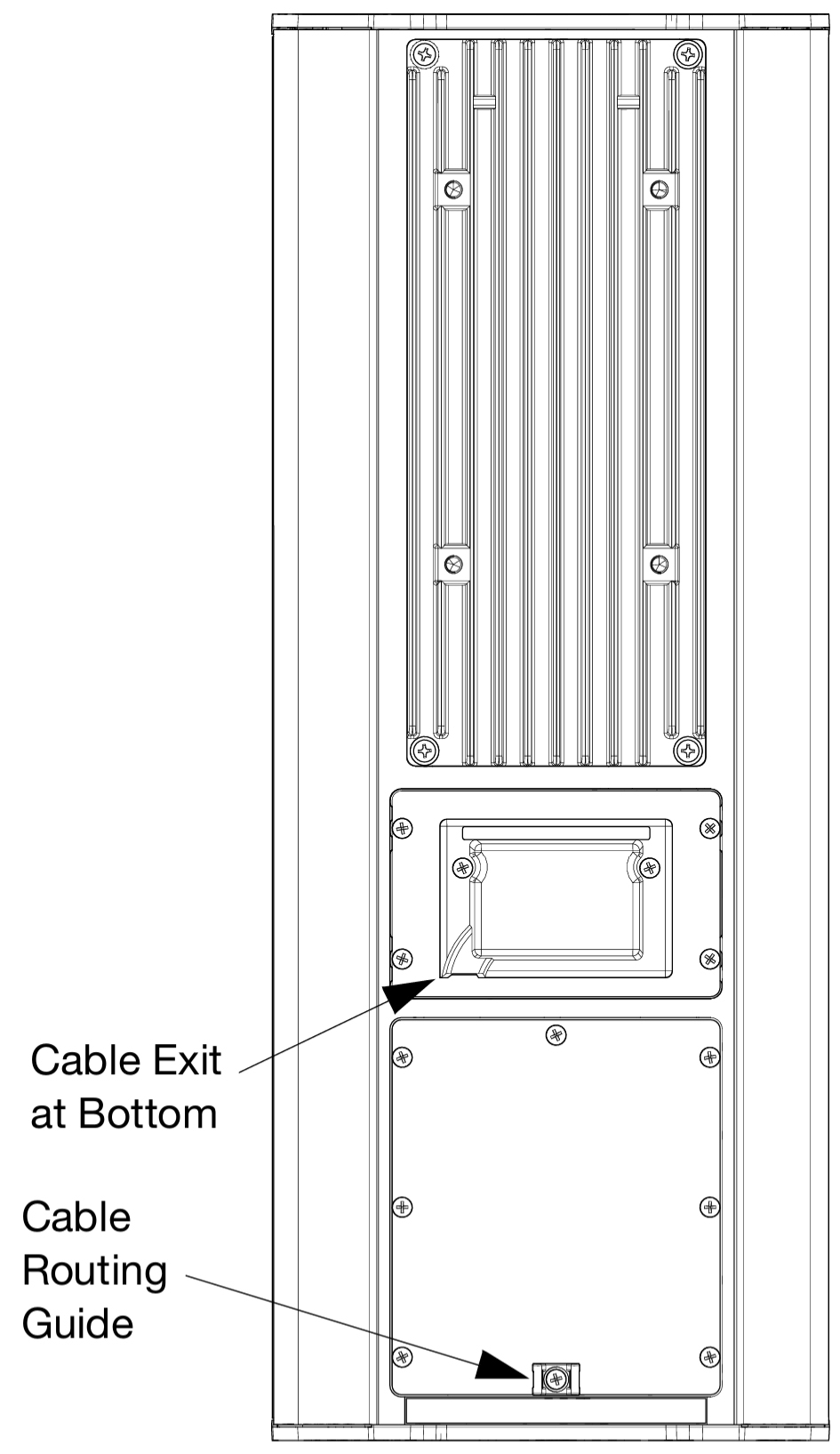
Only Permissible Vertical Orientation
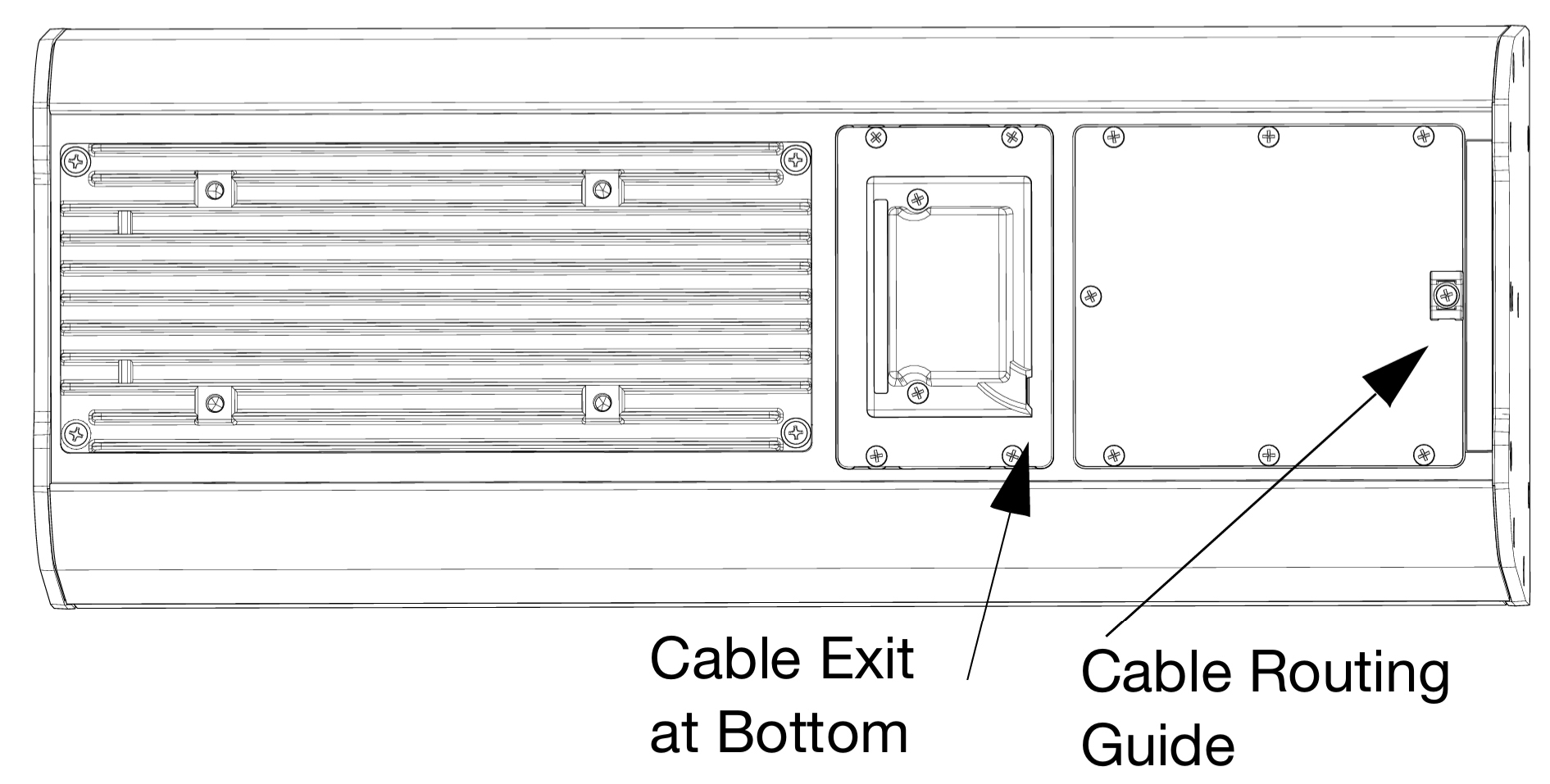
Only Permissible Horizontal Orientation
Downtilt and Uptilt
Caution
The weather-protected ULTRA-X20XP/22XP/23XP loudspeaker must be mounted with a 0° tilt, or preferably with a slight downtilt, as shown in the figures below, with the cables exiting from the bottom. This angle shields the driver from the elements and does not allow water to accumulate in the cabinet. Do not tilt the cabinet up, as the drivers and cabinet will accumulate water.
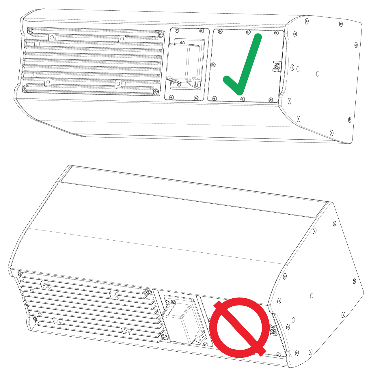
Downtilt Permissible (top); Uptilt NOT Permissible (bottom)
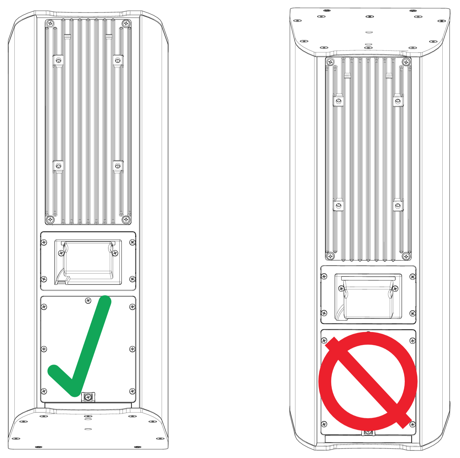
Downtilt Permissible (left); Uptilt NOT Permissible (right)
Horizontal Tilt
Caution
If tilting the loudspeaker from 0° horizontal, ensure that the horizontal tilt leaves the port below the electronics, as shown in the figure below, so that water does not enter from the port and accumulate in the cabinet.
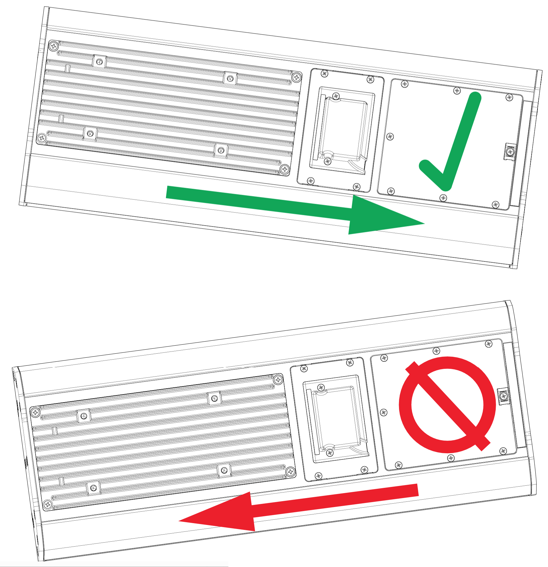
Horizontal Tilt-Away from Electronics Permissible (top); Horizontal Tilt-Toward Electronics NOT Permissible (bottom)
Assembling Phoenix-to-Phoenix Loudspeaker Cables
When connecting loudspeakers equipped with Phoenix connectors to the MPS-488HPp power supply, you need a Phoenix 5-pin female to Phoenix 5-pin female cable. The following procedure documents how to assemble this cable.
 |
Assembled Phoenix-to-Phoenix Cable
If the cable has not yet been stripped, strip one end of the cable. Strip the outer shielding by 1 inch and then strip the black, red, blue, and white wires by 0.275 inch.

Insert the five exposed conductors into the five cable holes in a Phoenix 5-pin female cable mount connector. Use the following wiring scheme.

Pin Destinations for Phoenix 5-Pin Female Cable Mount Connector
Secure the conductors by tightening the five screws in the Phoenix cable mount connector. Screws should be torqued to 5–6 Nm(4.4–5.3 In-Lbs).

Caution
Screws should not be inserted into the Phoenix connector while the connector rests in a mating plug. Doing so will damage the contacts. During assembly, the Phoenix connector should only be held in place externally.
Repeat the previous steps and attach the other end of the cable to another Phoenix 5-pin female cable mount connector.
Verify the wiring polarity is correct for both cable ends
Rotating the Horn
The ULTRA-X20XP and ULTRA-X22XP horns may be rotated for increased installation flexibility. However, care must be taken so as to not damage the loudspeaker.
Remove the grille by removing the four 8-32 x 0.5-inch flat-head Phillips screws (two on the top and two on bottom) of the loudspeaker grille.
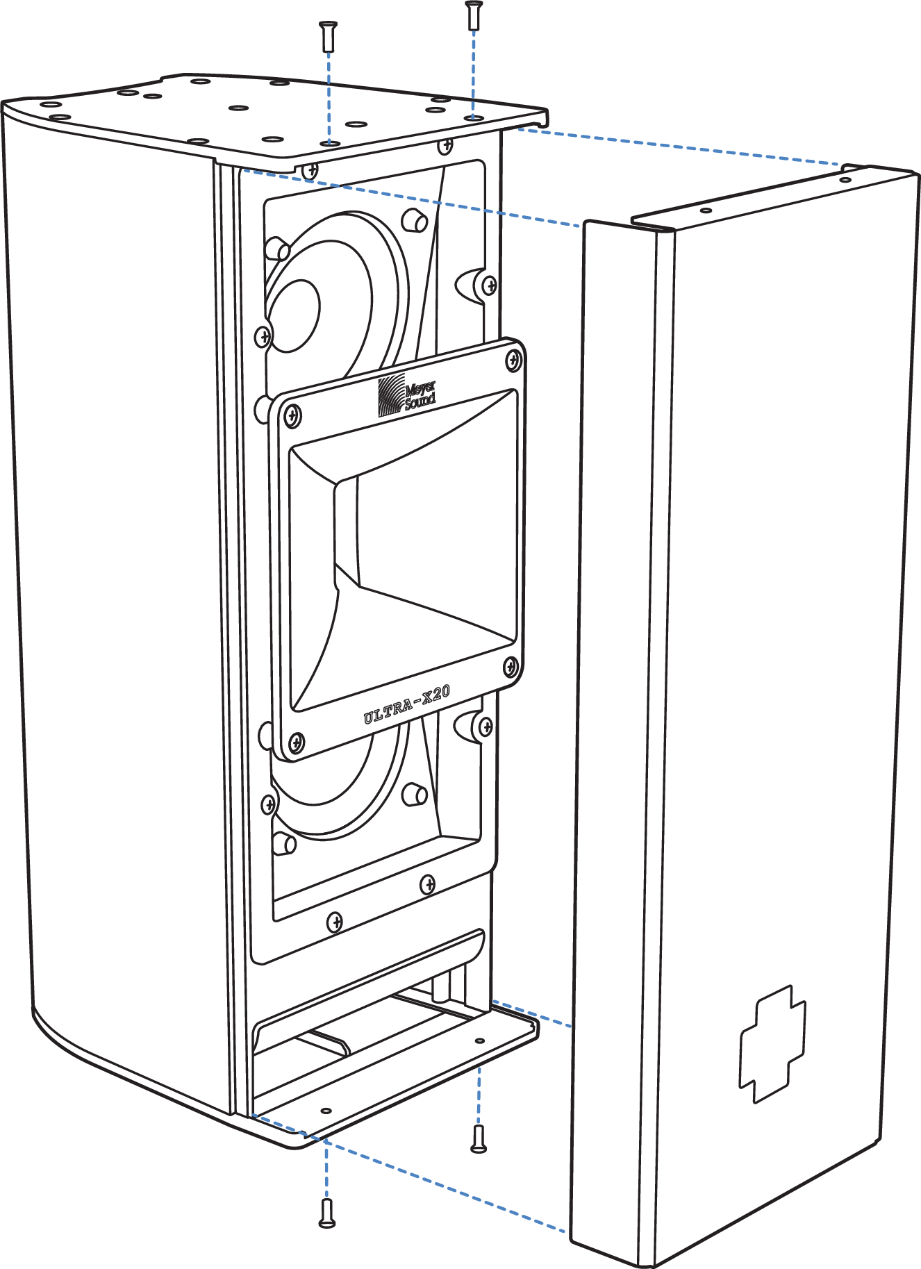
Remove ULTRA-X20XP Grille Frame.
Remove the four truss-head Phillips 8-32 x 0.5-inch screws holding the horn in place.
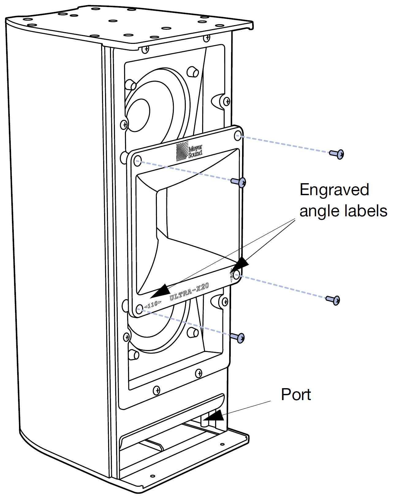
Removing Four Screws Holding the Horn in Place
Determine the present orientation of the horn by checking the horn throat orientation when the speaker is vertical with the port at the bottom. The cabinet is vertical and the horn is in the 110° horizontal by 50° vertical orientation when the Meyer Sound Logo on the horn and on the bezel are at the top, the horn throat is in the vertical orientation, and the 110° emboss is also horizontal, as shown in the figure below.
The cabinet is vertical and the horn is in the 50° horizontal by 110° vertical orientation when the Meyer Sound Logo on the horn is on the right, the horn throat is in the horizontal orientation, and the 50° emboss is also horizontal, as shown in the second figure below.
To rotate the horn from 110° x 50° to 50° x 110°, pull the horn out and rotate it 90°, so that the horn throat is oriented horizontally, the Meyer Sound Logo on the horn is on the right, and the 50° emboss is also horizontal, as shown in the second figure below.
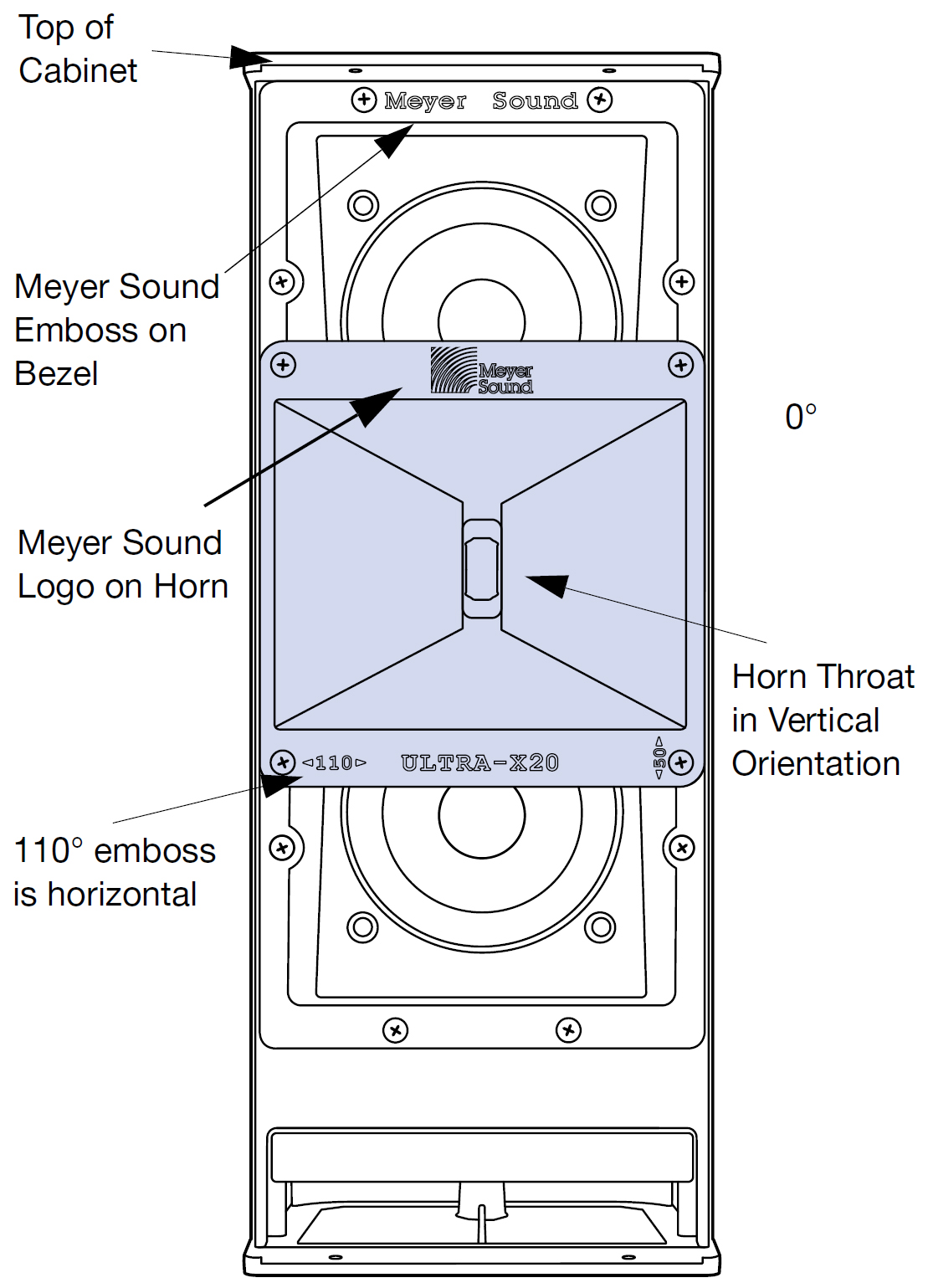
110° horizontal by 50° vertical horn orientation
To rotate the horn from 50° x 110° to 110° x 50°, pull the horn out, rotate it -90°, so that the horn throat is oriented vertically, the Meyer Sound Logo on the horn is on the top, and the 110° emboss is also horizontal, as shown in the figure above.
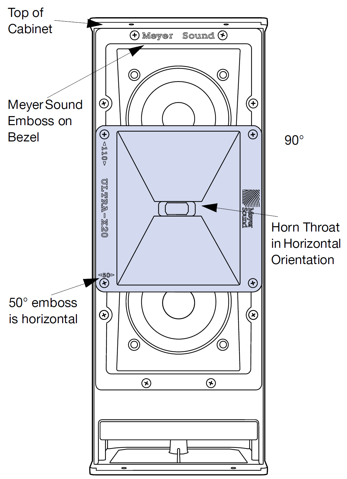
50° horizontal by 110° vertical horn orientation
Replace the four screws removed in Step 2 to re-secure the horn into position. Be sure to use the 8-32 x 0.5-inch screws. The recommended torque value for the horn screws is 12 in-lb (1.36 N·m).
Replace the grille and secure it with the four 8-32 x 1.00-inch screws removed in step 1. MeyerSound recommends applying blue thread locker (medium strength) to screws in the leading three threads before replacing. The recommended torque value for the grille screws is 8 in-lb (0.90N·m).
Note
In the paragraphs above, instructions and graphics for the ULTRA-X20XP are used. The same procedure holds for the ULTRA-X22XP (with 110° replaced by 80°). The ULTRA-X23XP is symmetrical; rotation is possible but not necessary.
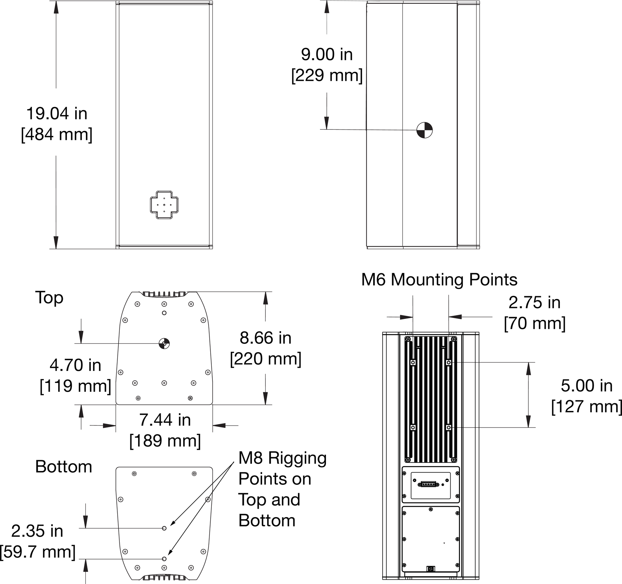
ULTRA-X20XP/22XP/23XP Loudspeaker Dimensions
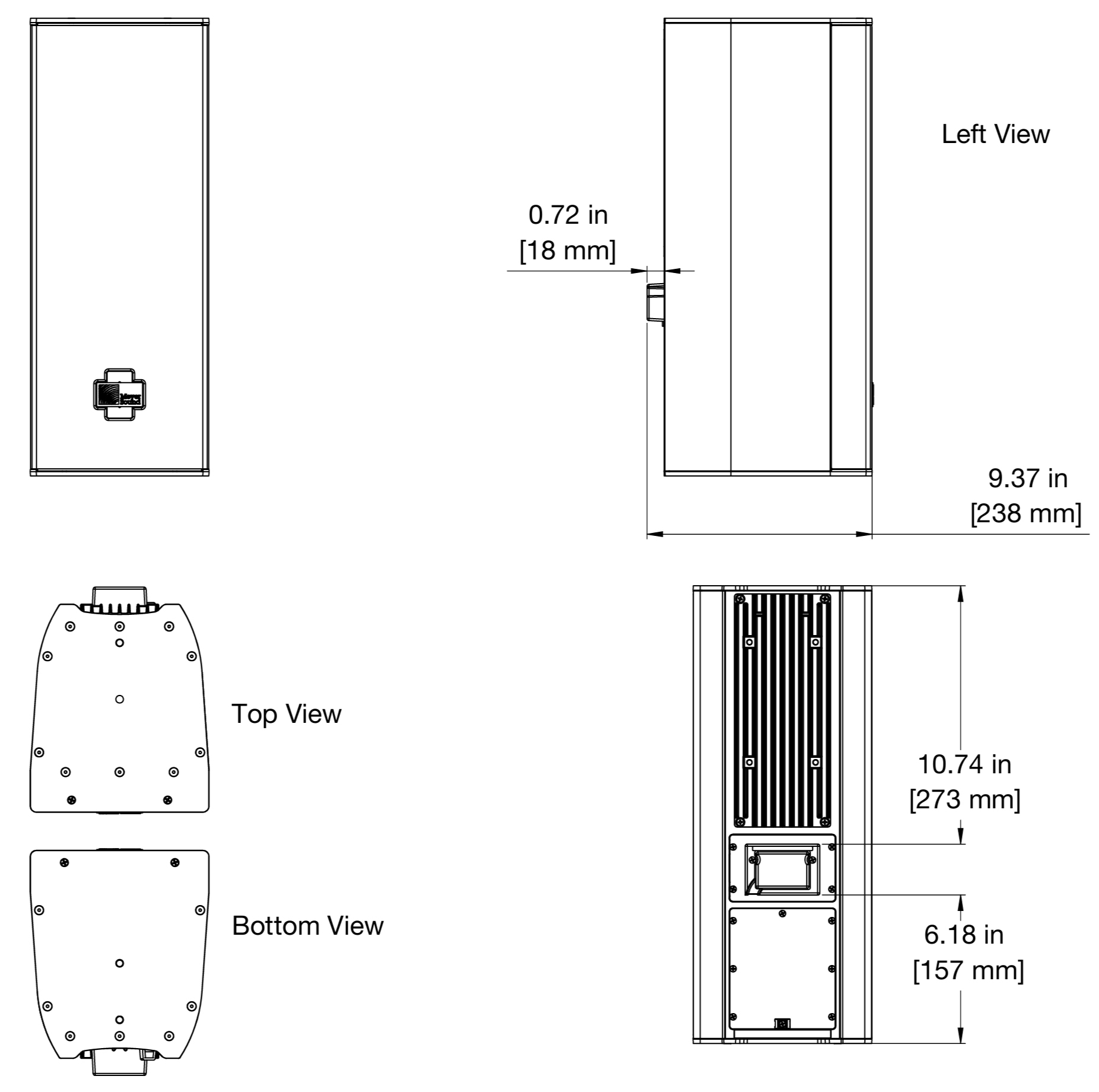
ULTRA-X20XP with Rain Hood Dimensions
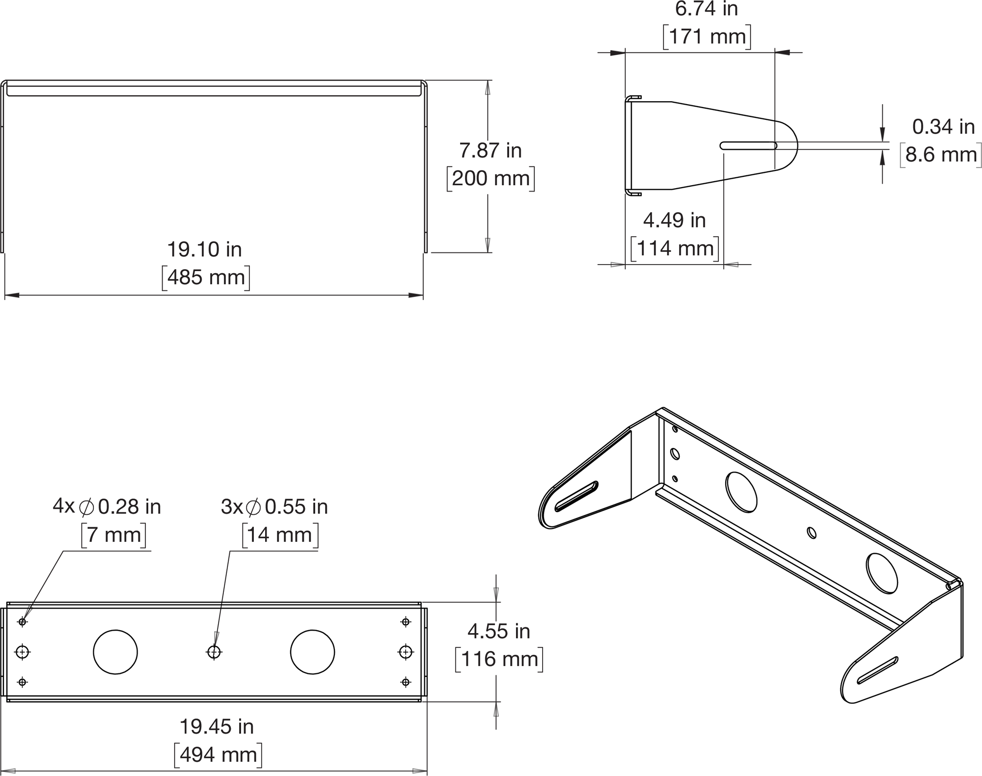
MUB-X20 Dimensions
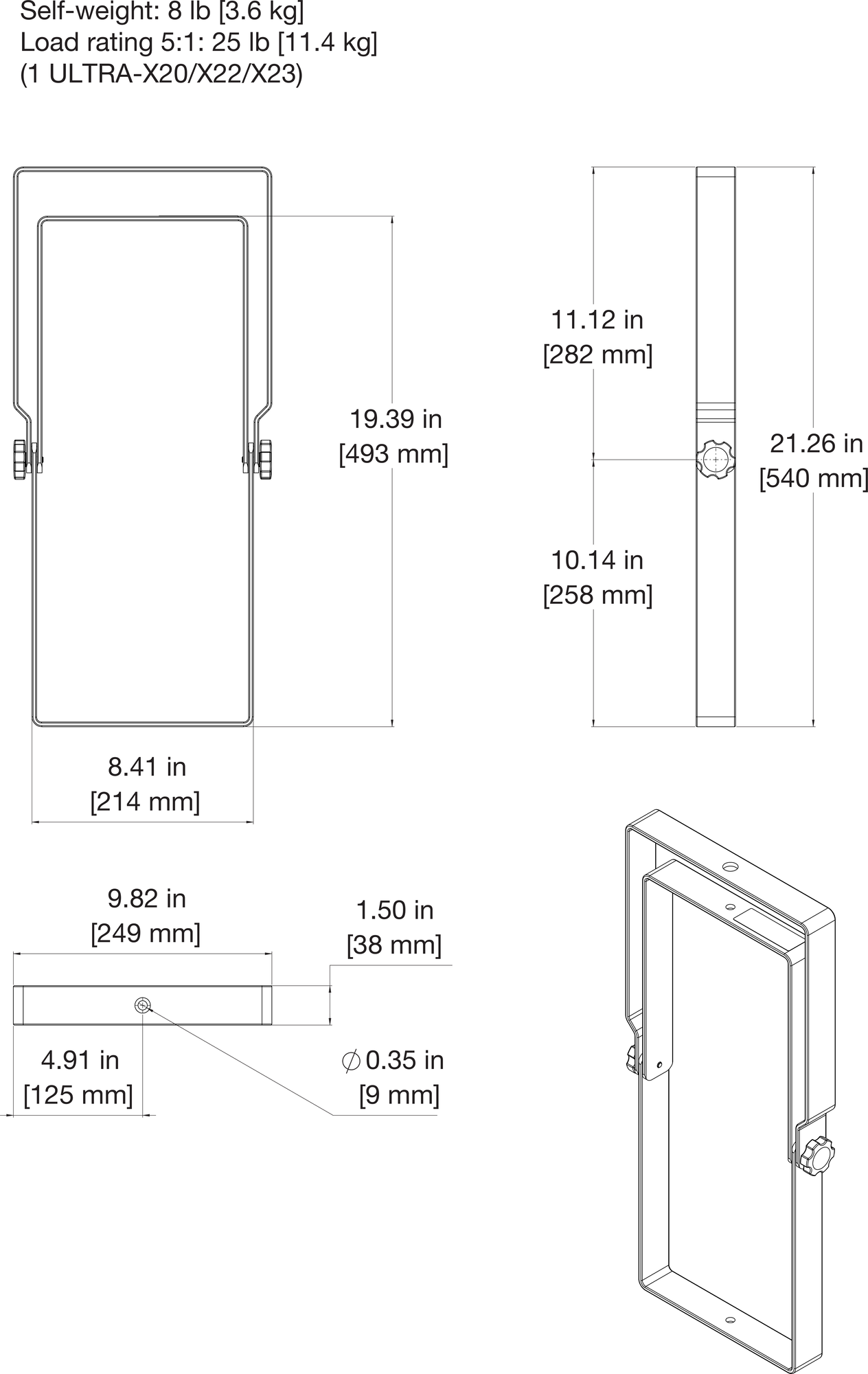
MYA-X20 Dimensions
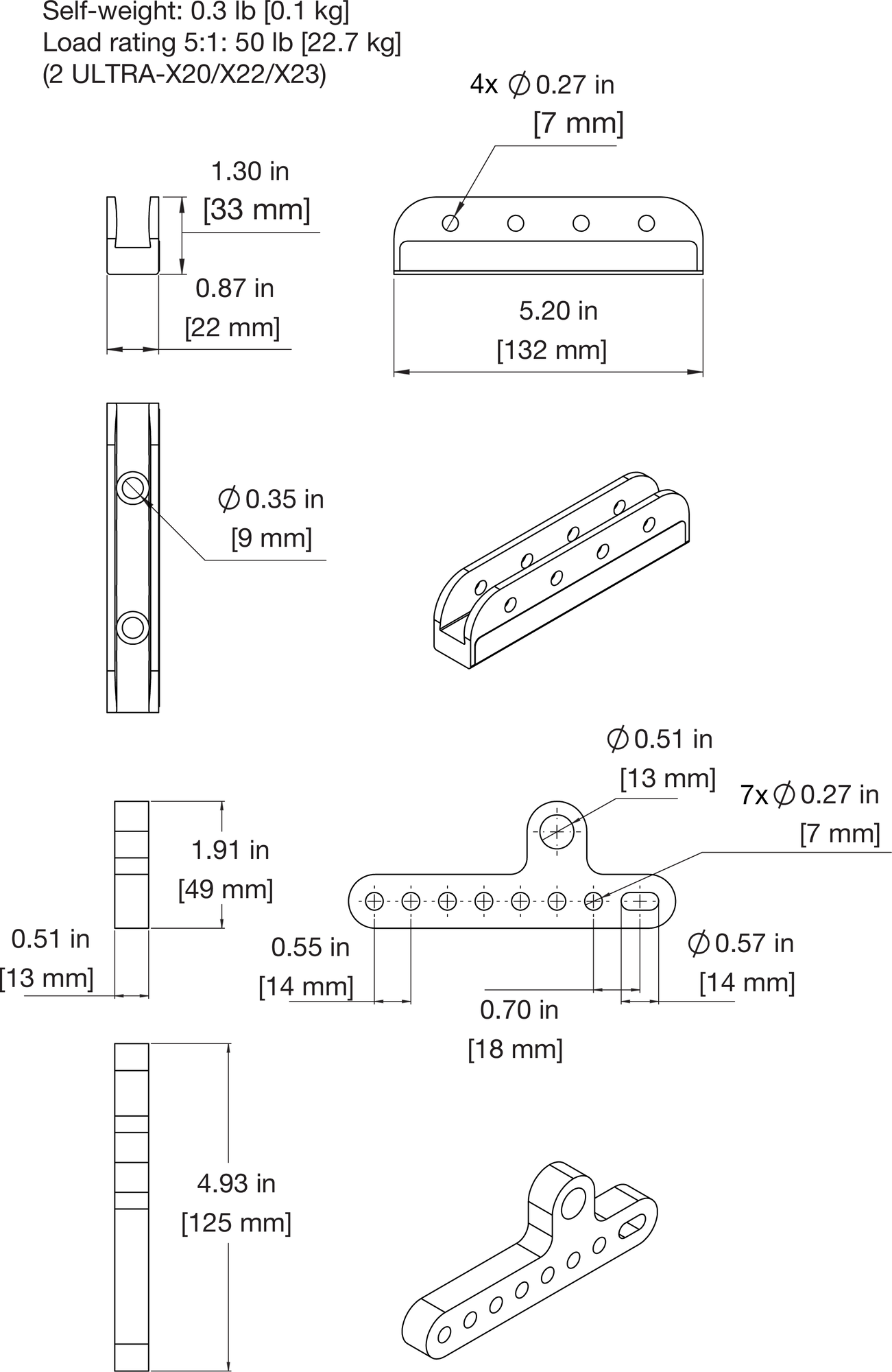
MTC-X20 Dimensions
