Assembly Guide — ASTRYA-140
Screen channel loudspeaker


This document describes the assembly of the ASTRYA-140 loudspeaker and serves as an addendum to Operating Instructions — ASTRYA-140, where additional product information can be found.
Caution
Disconnect AC power before assembly. Make all electrical connections after assembly and before turning on AC power.
Requires installation by an instructed person. Contact Meyer Sound Technical Support for additional information: meyersound.com/contact.
Important safety considerations
When installing Meyer Sound loudspeakers, always observe the following precautions:
Use all Meyer Sound products in accordance with local, state, federal, and industry regulations. Owners and users are responsible for evaluating the reliability of any rigging method for their application. Rigging should only be done by experienced professionals.
Use mounting and rigging hardware rated to meet or exceed the weight being hung. Make sure to attach mounting hardware to the building's structural components (studs or joists) and not just to the wall surface. Verify that the building's structure and the anchors used for the installation will safely support the total weight of the mounted loudspeakers.
Use mounting hardware appropriate for the surface where the loudspeaker will be installed.
Make sure the fasteners are tightened securely. Meyer Sound recommends using medium-strength thread locker on fastener threads.
Inspect mounting and rigging hardware regularly. Immediately replace any worn, bent, or damaged components.
Components
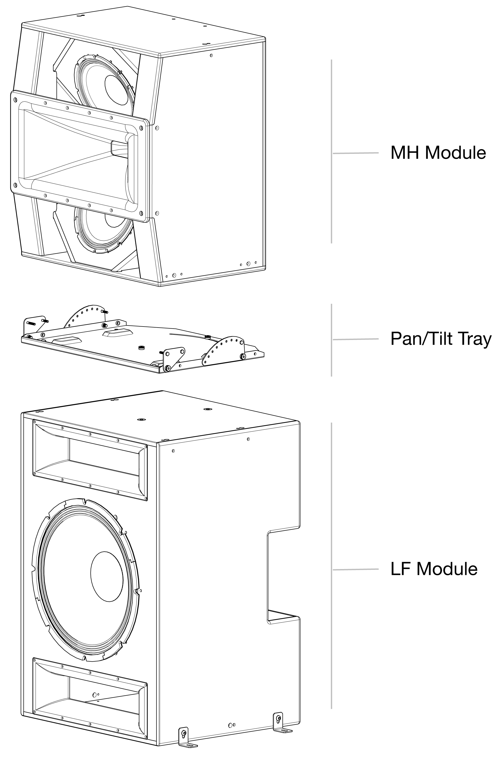
The ASTRYA-140 cinema screen channel loudspeaker ships in two cartons. One carton contains the Mid-High (MH) module, a power connector, and a network connector. The other carton contains the Low-Frequency (LF) module with the pan/tilt tray mounted to it, the pan/tilt connection hardware, and the module link cable that connects the MH to the LF module.
Note
ASTRYA-140 does not ship with fasteners to secure the included L-brackets to the mounting surface. The user must provide fasteners that are sufficiently rated and sized.
The table below lists the hardware related to the ASTRYA-140 pan/tilt tray that is not pre-installed.
Meyer Sound Part Number | Description | QTY | Use |
|---|---|---|---|
101.873 | Screw, shoulder, 12 mm x 6 mm, M8 x 1.25-inch x 16 mm, black oxide | 4 | Links to tray |
101.874 | Screw, hex head, partial thread, 1/4 – 20 x 1.25-inch, stainless, black oxide | 6 | Links to MH |
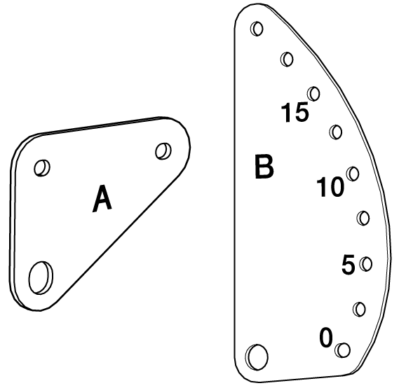
45.329.105.01 | Pivot link plate (A) | 2 | Links tray to MH |
45.329.103.01 | Angle link plate (B) | 2 | Links tray to MH |
Required tools
The following user-supplied tools are required for assembling ASTRYA-140.
7/16-inch socket with ratchet wrench, 7/16-inch end wrench, or adjustable wrench
1/4-inch socket for ratchet wrench
Metric Allen wrench set
Assembly procedure
Follow these steps to assemble the ASTRYA-140 loudspeaker in its final position, or complete the assembly and then move the entire loudspeaker into its final position.
From the product packaging, remove the LF module (includes Pan/Tilt Tray), the HF module, the four (4) link plates, and the fastening hardware.
Place the LF unit in its final position or on the floor in the assembly location.
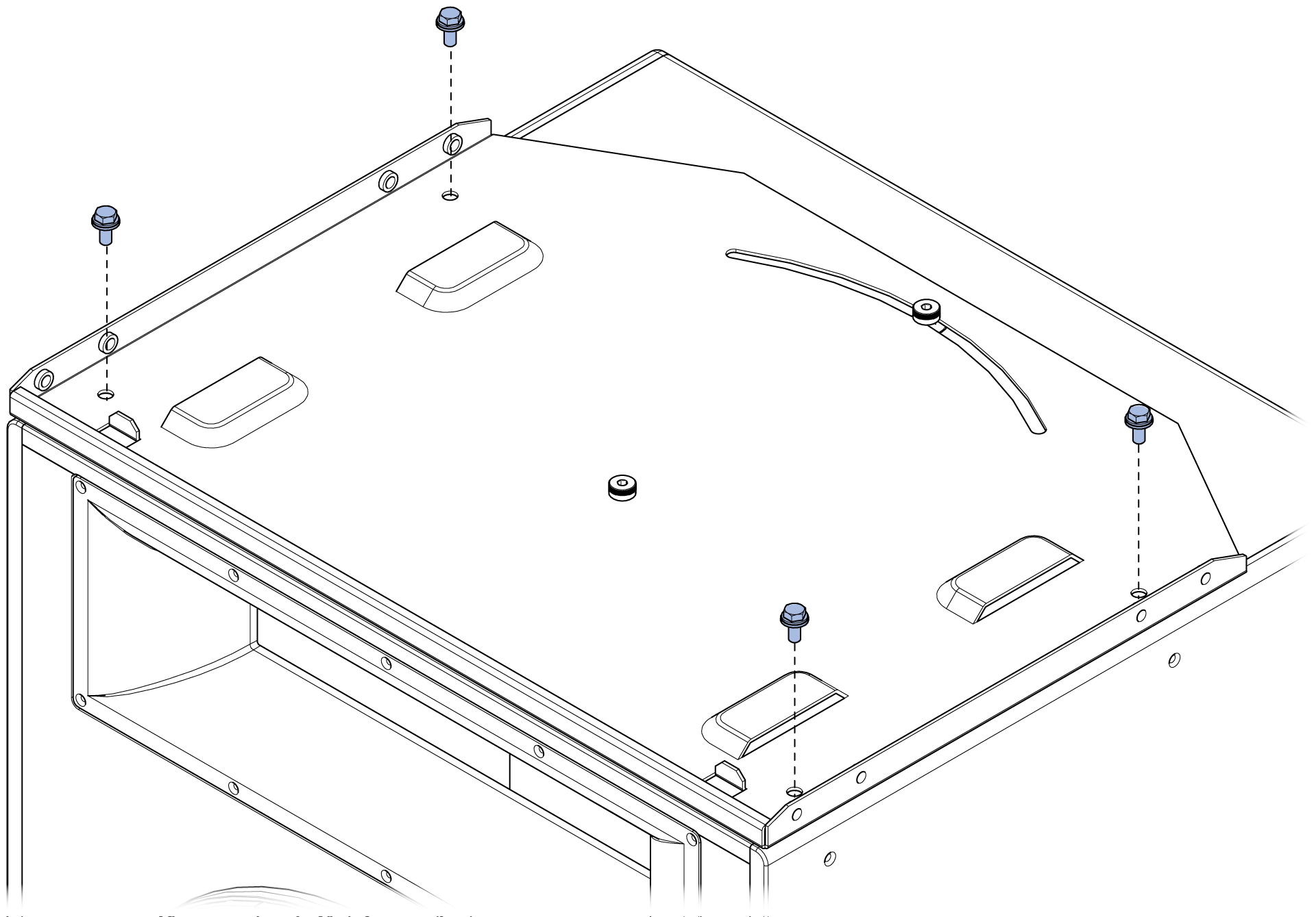
If the MH module is to be “panned” or rotated horizontally relative to the LF module, remove the four hex-head screws in the corners of the Pan/Tilt Tray.
Caution
Once these screws are removed, the loudspeaker assembly must be supported only from the bottom of the LF module and cannot be suspended from the MH module. Do not suspend the entire loudspeaker from the rigging points on the top of the MH module if the four hex-head screws in the corners of the Pan/Tilt Tray are removed.
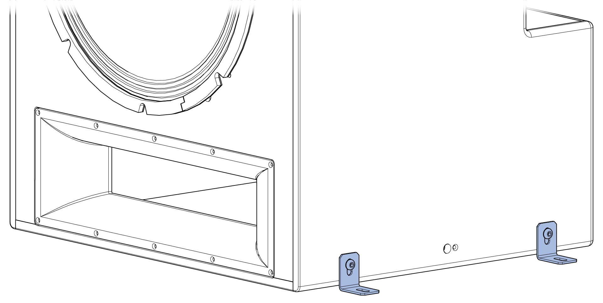
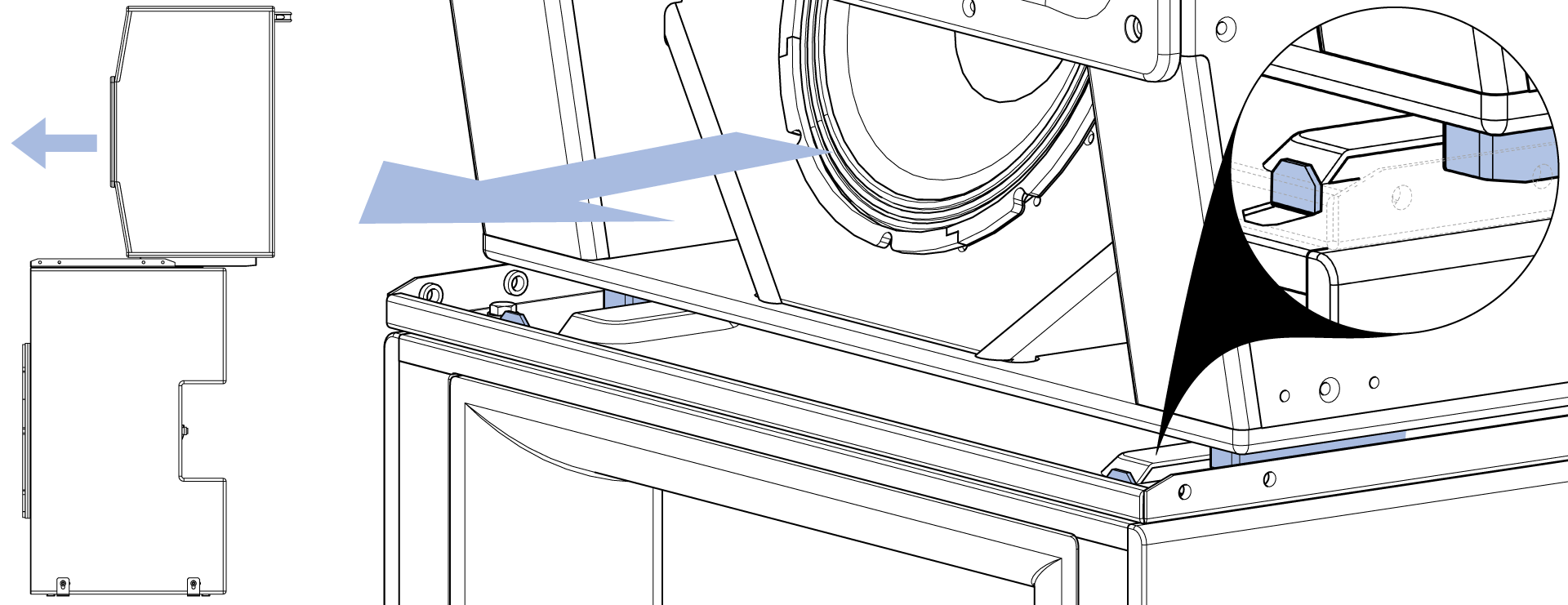
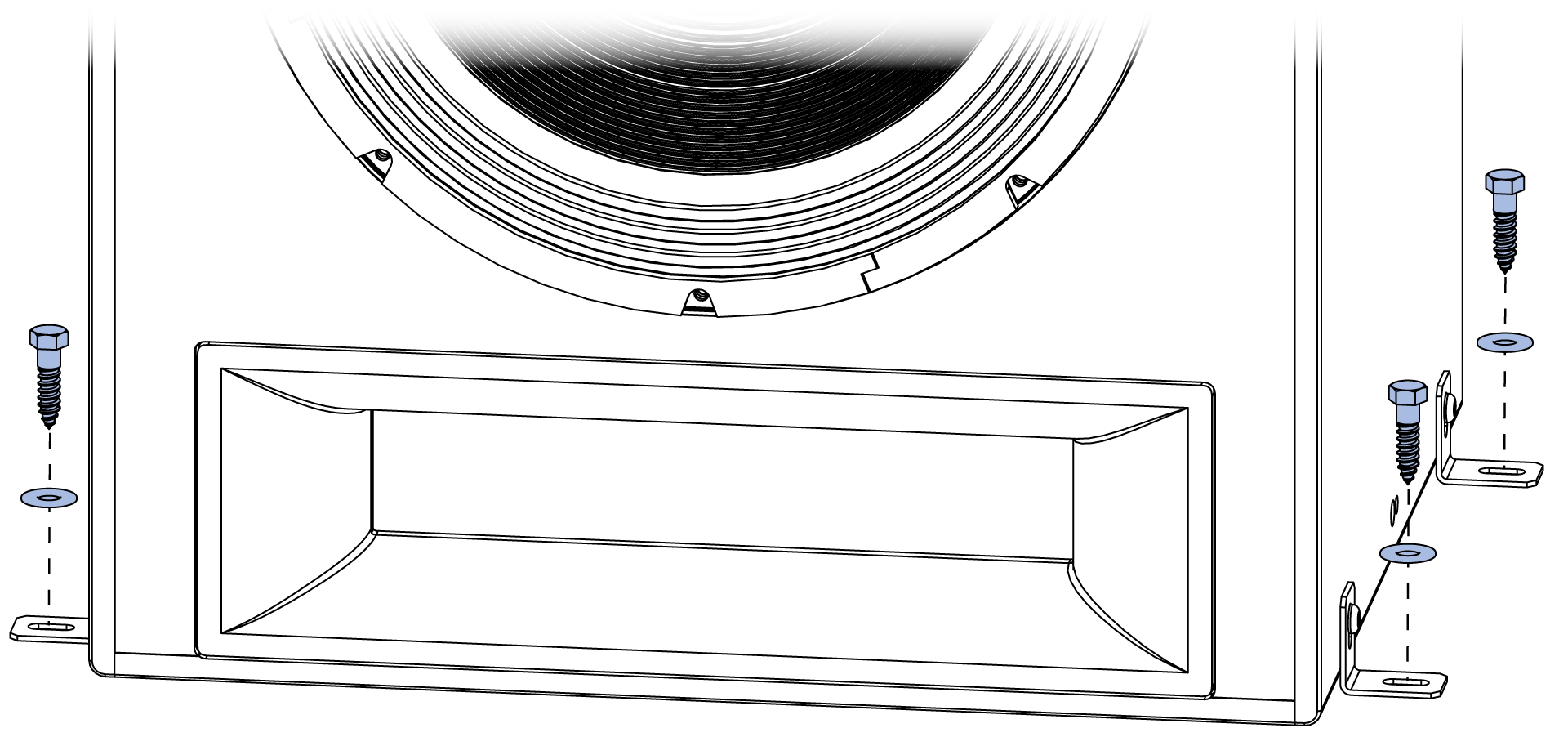
Remove the fasteners that secure the L-brackets to the LF module, turn the L-brackets around, and mount them to the LF module as shown below.
If assembling the loudspeaker in its installed location, secure the LF module to the mounting surface using hardware appropriate for the mounting surface material (fasteners not included).
Locate the MH module behind the LF module. With one person on each side of the MH module, rock the cabinet back, then lift the MH module onto the Pan/Tilt Tray.
Note
It is possible to locate the MH module in front of the LF module to stack them, though it is slightly more difficult. Take care not to push the MH module too far -- off the rear of the LF module.
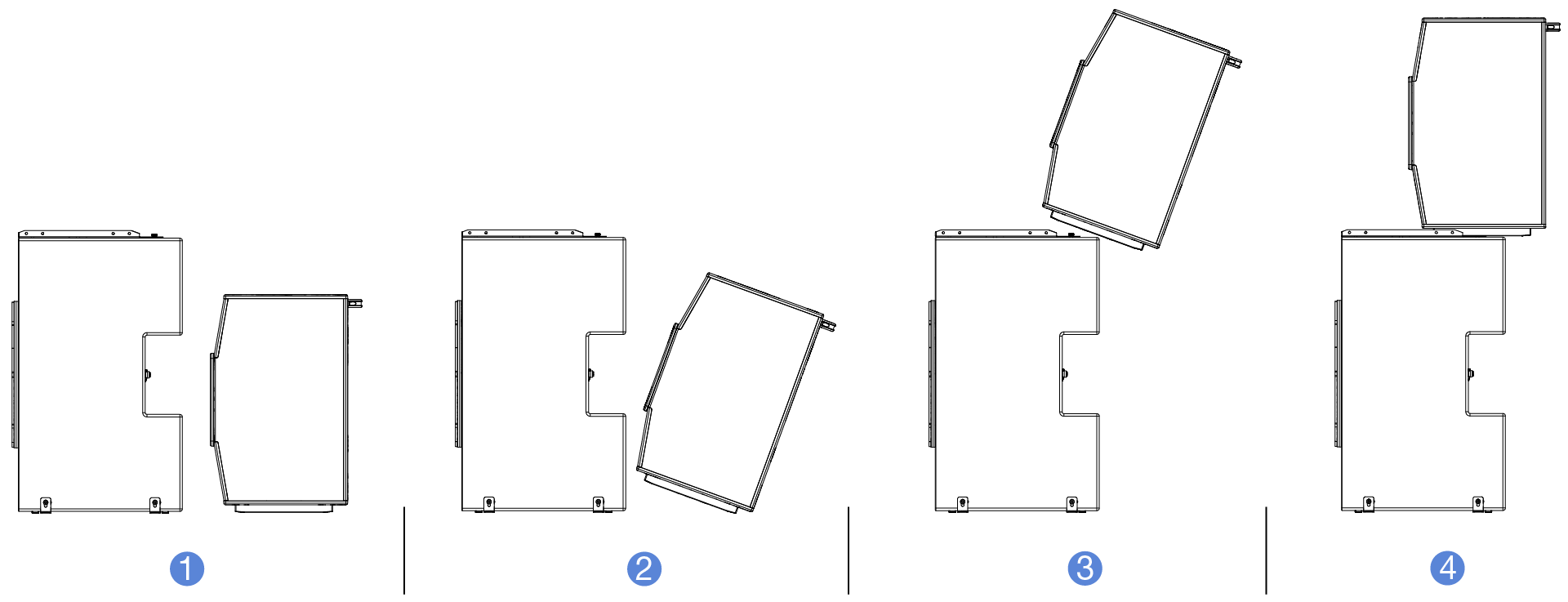
Slide the MH module forward until the skids of the MH module locate against stops on the Pan/Tilt Tray. The front edge of the MH module will align with the front of the Pan/Tilt Tray when it is properly located.
Link configuration
Depending on whether the MH module is to be tilted up or down as specified in the system design, the tilt links are mounted in different positions. The steps to assemble the modules are listed in two sections below, one for tilting the MH module down, the other for tilting it up:
If the system design does not call for any tilt, either link configuration facilitates zero degrees of tilt relative to the LF module. Even when there is no tilt, the links must be installed to secure the MH module.
The A links provide the rotation point, while the B links provide +/- 20 degrees of tilt in 2.5-degree increments, depending on the hole used to secure them to the MH module.
Link configuration - downtilt
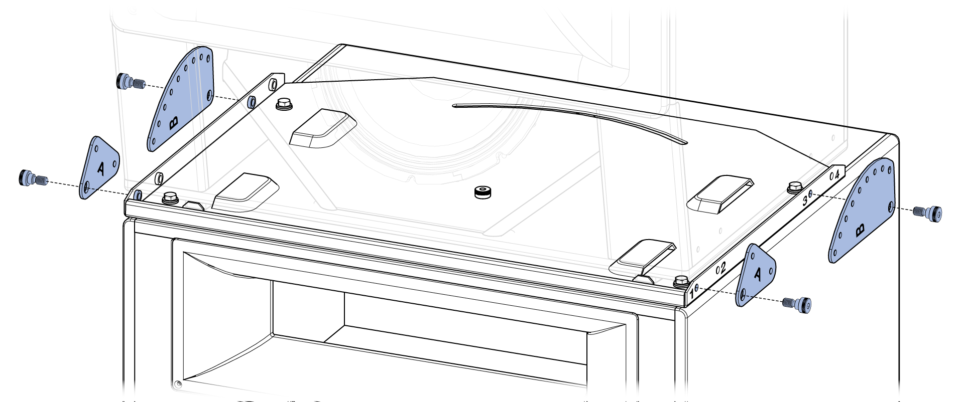
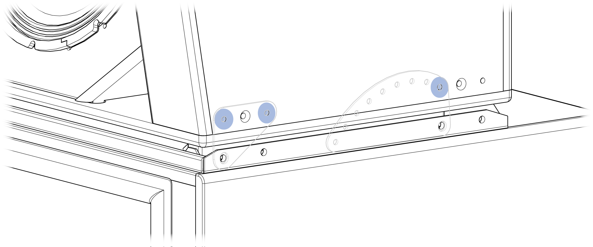
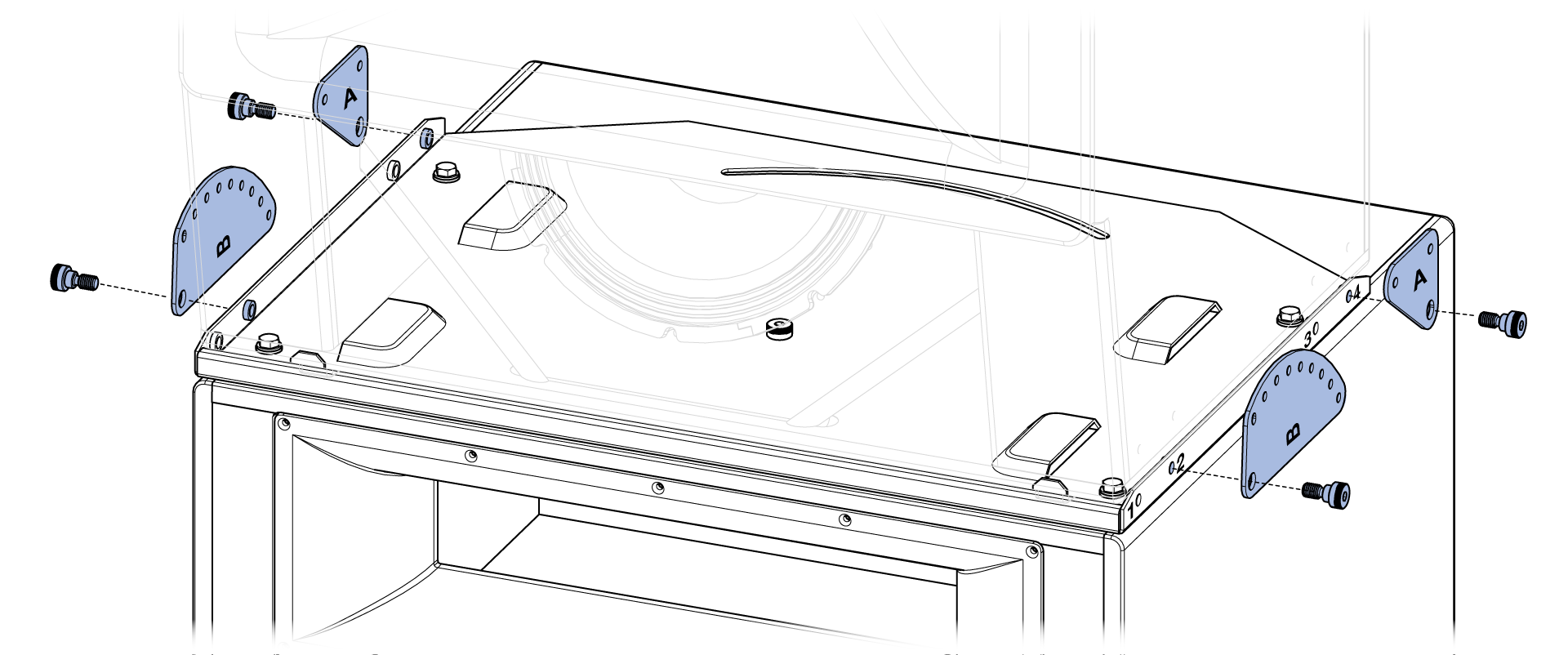
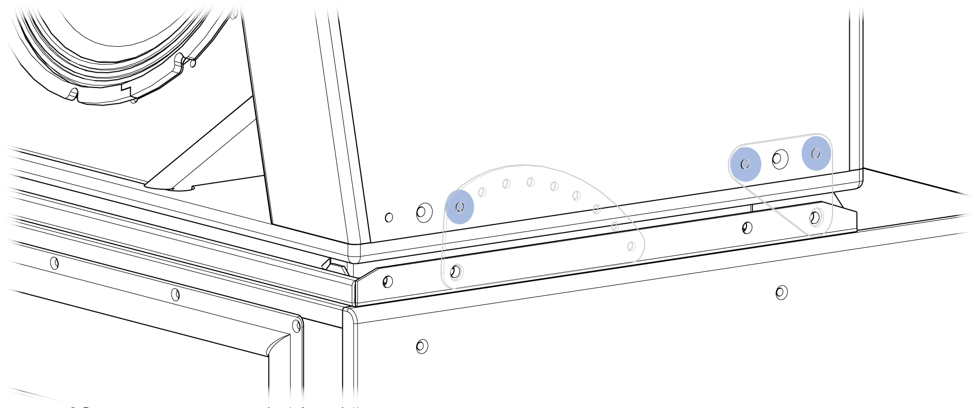
When the MH module will be tilted down, locate and orient the A and B links as shown below -- A links to Tray hole 1, B links to Tray hole 3. Secure them to the Pan/Tilt Tray with the four shoulder screws (PN 101.873).
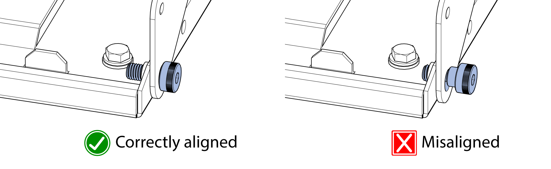
Ensure the holes in the A and B links are aligned with the shoulder of the shoulder screws. The links should still rotate when the screws are tightened.
These locations on the MH module are used to secure the links when the MH module is tilted down.
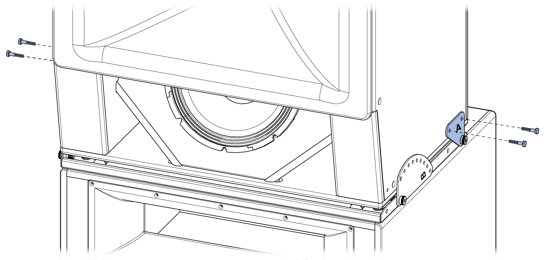
Rotate both A links and secure each of them to the MH module with two of the hex-head 1/4 - 20 screws (PN 101.874).
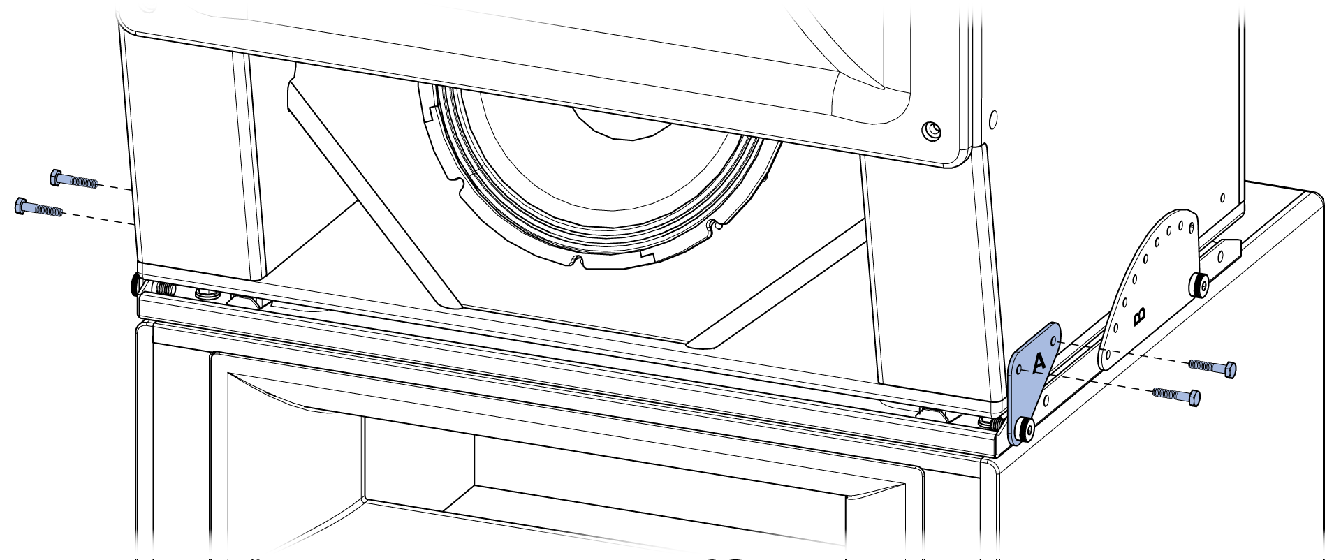
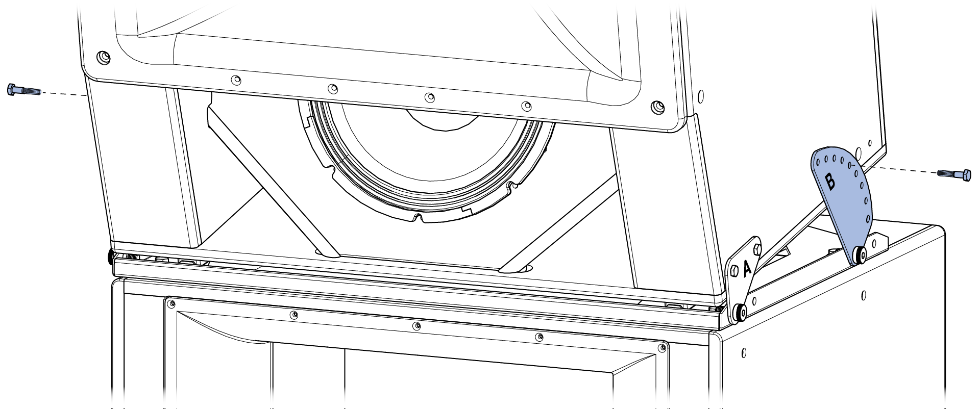
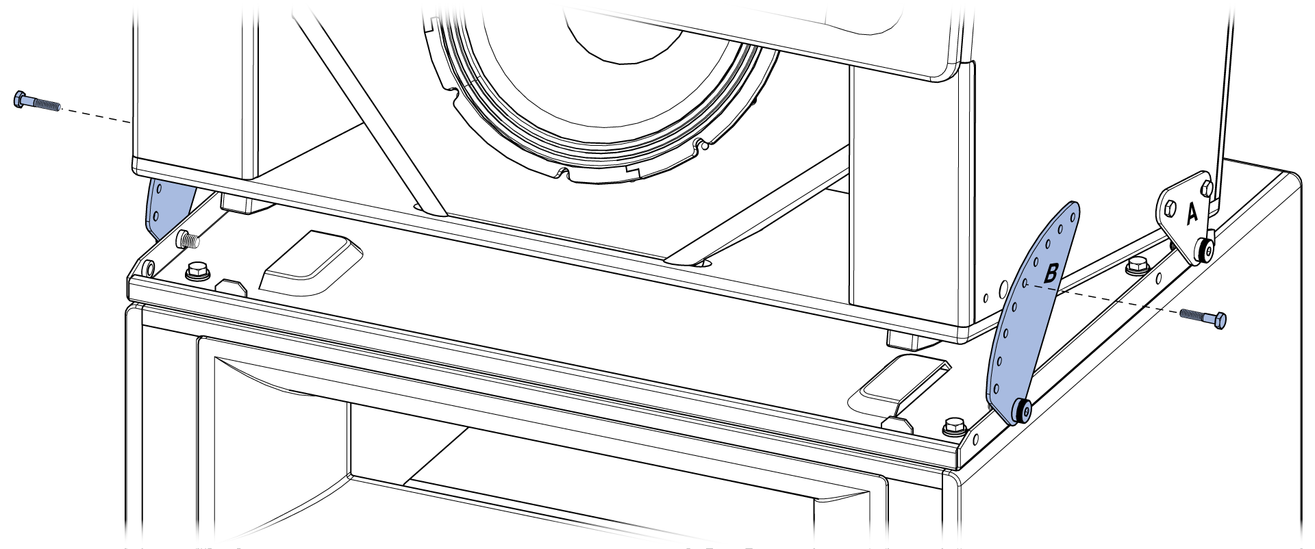
In the system design documentation, look up the amount of tilt for the MH module. Identify the corresponding angle hole on the B link and tilt the MH module until the identified hole on the B link aligns with the mounting hole on the MH module (10-degree tilt illustrated below). Secure the B links to the MH module on both sides of the enclosure with the included hex-head 1/4 - 20 screws (PN 101.874).
Link configuration - uptilt
When the MH module will be tilted up, locate and orient the A and B links as shown below -- A links to Tray hole 2, B links to Tray hole 4. Secure them to the Pan/Tilt Tray with the four shoulder screws (PN 101.873).
Ensure the holes in the A and B links are aligned with the shoulder of the shoulder screws. The links should still rotate when the screws are tightened.
These locations on the MH module are used to secure the links when the MH module is tilted up.
Rotate both A links and secure each of them to the MH module with two of the hex-head 1/4 - 20 screws (PN 101.874)
In the system design documentation, look up the amount of tilt for the MH module. Identify the corresponding angle hole on the B link and tilt the MH module until the identified hole on the B link aligns with the mounting hole on the MH module (10-degree tilt illustrated below). Secure the B links to the MH module on both sides of the enclosure with the included hex-head 1/4 - 20 screws (PN 101.874).
Pan the MH module
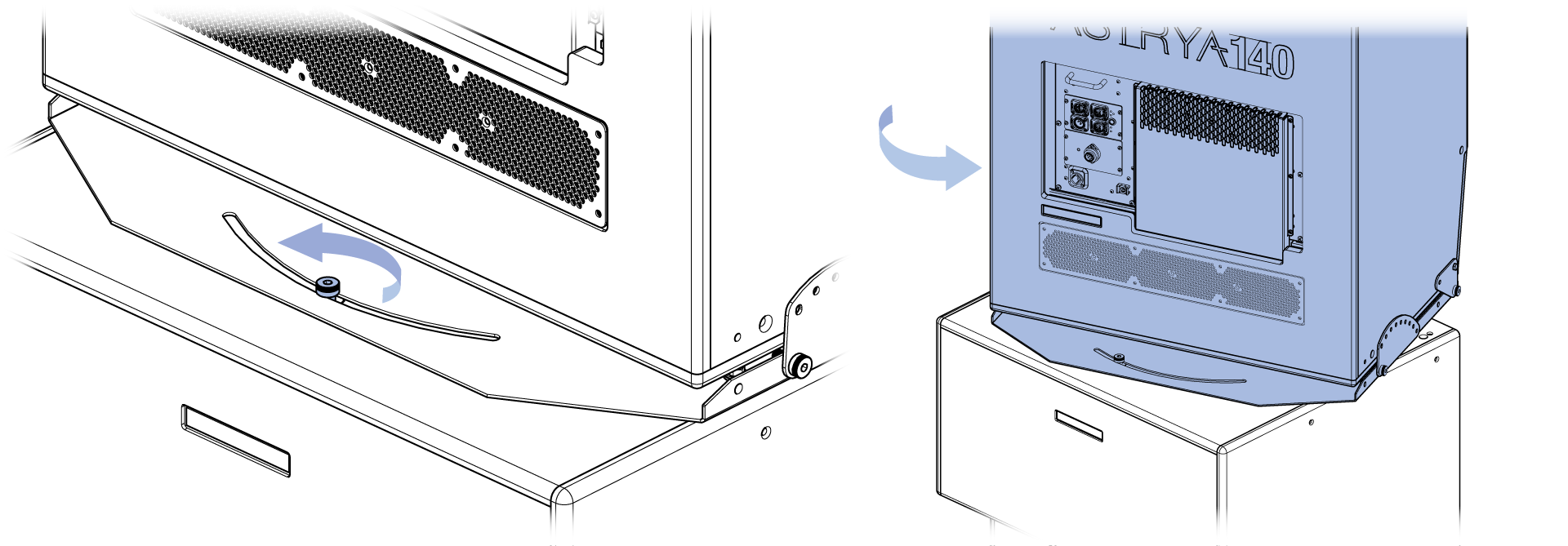
If the system design calls for the MH module to be panned horizontally relative to the LF module, loosen the shoulder screw that secures the Pan/Tilt Tray, rotate the MH module to the desired angle (+/- 30 degrees), and tighten the shoulder screw to prevent further movement.
Note
If the four hex-head screws were not removed before the MH module was mounted to the LF module, panning the MH module is not possible.
Secure assembled loudspeaker
If the loudspeaker was not previously secured to the mounting surface, move the loudspeaker to its final position and secure the L-brackets to the mounting surface with appropriately sized and rated fasteners.
Link cable
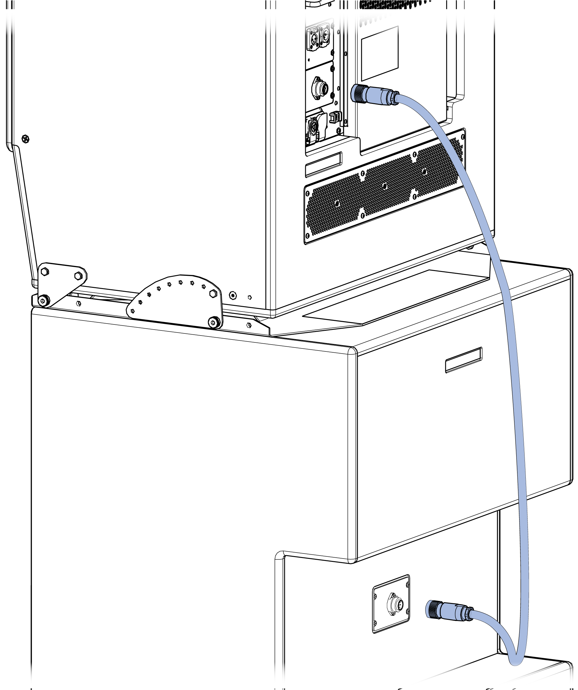
While the loudspeaker is still powered off, mate one end of the included link cable to the connector on the rear of the LF module, and the other end to the connector on the rear of the MH module.
Note
If the Link cable is connected after power has been applied, the amplifier module will indicate an error. Power down the loudspeaker, wait five minutes, and make the Link cable connections.
Additional Information
See Operating Instructions — ASTRYA-140, for additional information about this product, including how to assemble the power, analog audio, and network connectors, as well as power requirements and performance specifications.
Important
Meyer Sound recommends using Neutrik TOP cable connectors in all applications to ensure secure, long-term connectivity. Using connectors other than Neutrik TOP models may lead to degraded system performance.