Neutrik NAC3F-TRUE1-S Connector Assembly Instructions

This procedure provides the steps to terminate a power cable with a Neutrik NAC3M-TRUE1-S connector, Meyer Sound PN 466.091. The powerCON TRUE1 series of connectors is designed and certified as appliance couplers with breaking capacity as specified by IEC 60320-1, EN IEC 60320-1, UL 60330-1, and CSA C22.2 No. 60320-1. These standards qualify these assemblies for mating and unmating while the circuit is energized. According to IEC 60320-1, appliance couplers are suitable for use in cord sets, and Neutrik NAC3F-TRUE1-S.
The assembly of powerCON TRUE1 connectors must be completed only by a qualified person. Contact Meyer Sound Technical Support for additional information: meyersound.com/contact.
Warning
Improper termination or connector assembly can present a shock hazard and/or damage the product.
For safety reasons, this connector must be replaced if any parts are broken or if it shows excessive wear.
Caution
To maintain the IP rating of this connector, do not apply bending forces to the cable as it enters the connector. To avoid forces, strain relief the cable using the cable tie-downs available on the rear of the loudspeaker. To prevent water from traveling along the cable to the connector when outdoors, remember to add a drip loop to the cable routing.
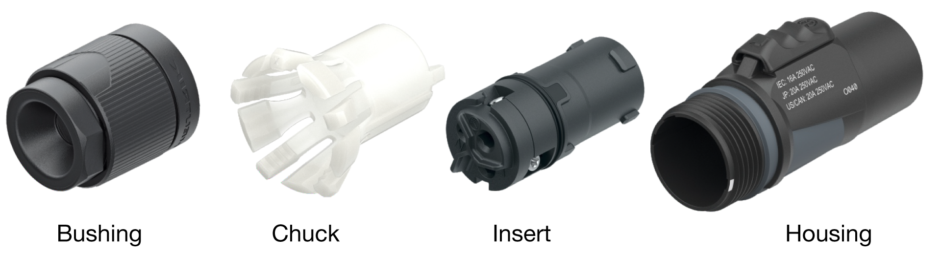
NAC3F-S parts
Required tools
Cable and wire prep tools – wire stripper, etc.
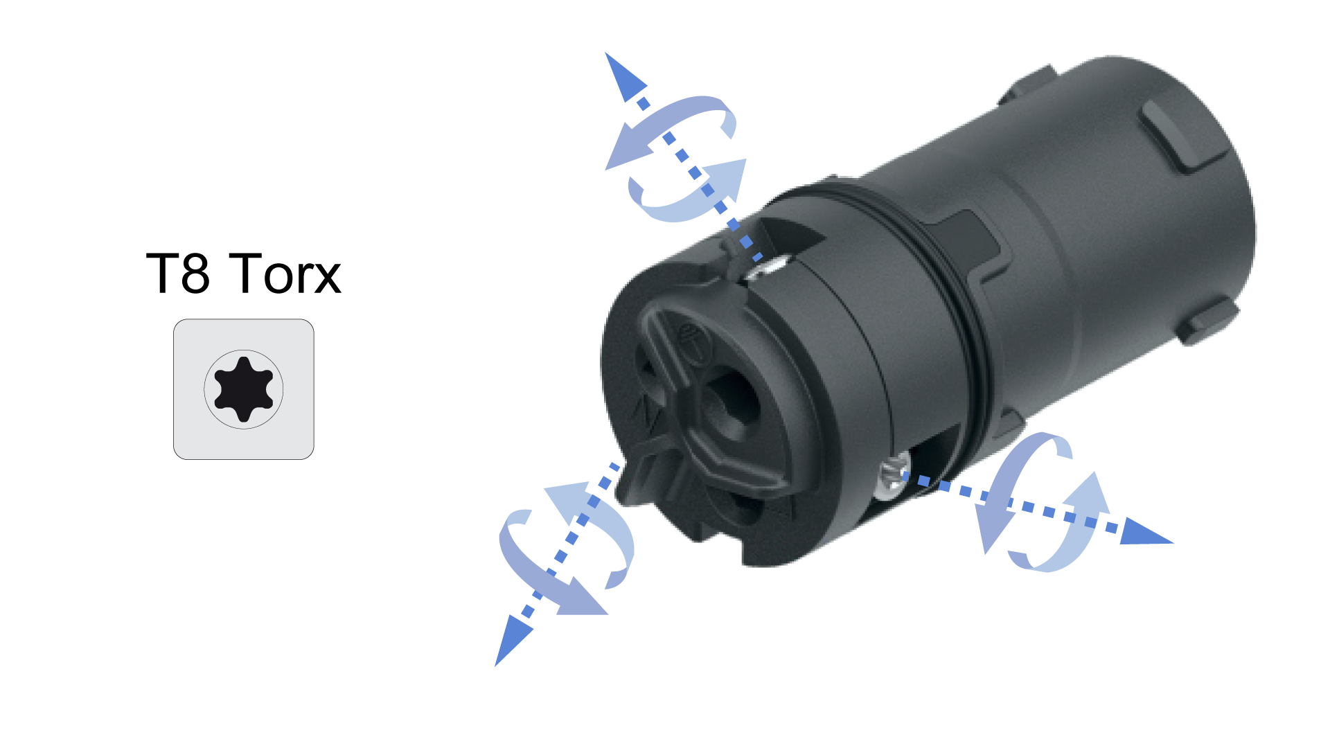
Torx T8 screwdriver or torque tool
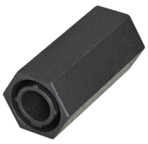
Neutrik insert tool: HTLACA *
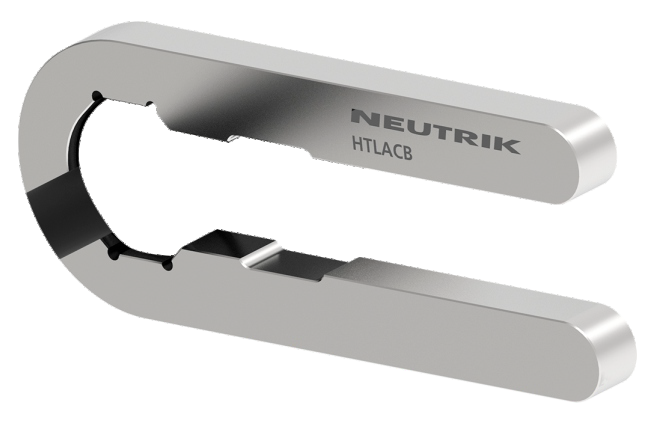
Neutrik bushing tool: HTLACB *
Torque wrench
27mm or 1-1/8” socket for torque wrench
Cable lubricant (when required)
* (3D printing files available at Neutrik.com)
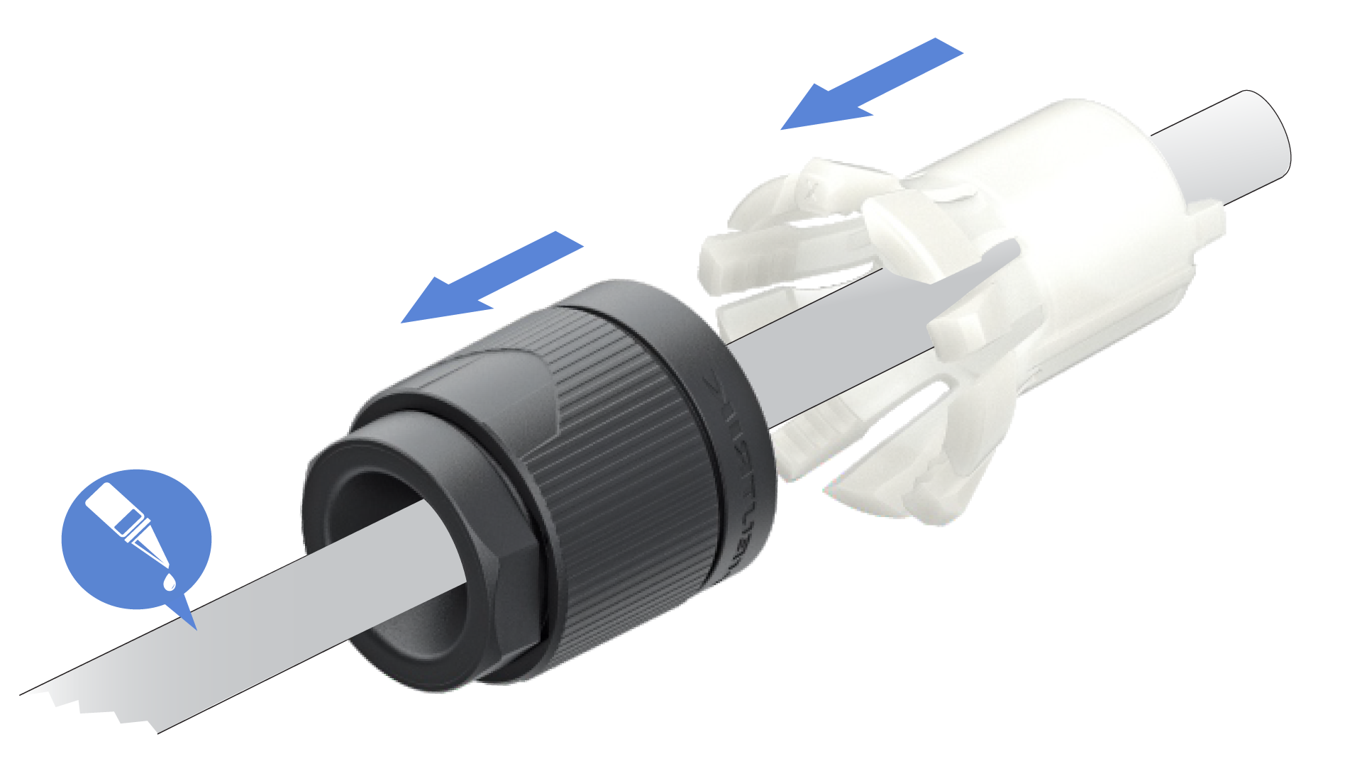
Apply cable lubricant if needed, slide the bushing and chuck onto the cable.
Note
The bushing and chuck cannot be slid onto the cable after the insert is connected to the conductors.
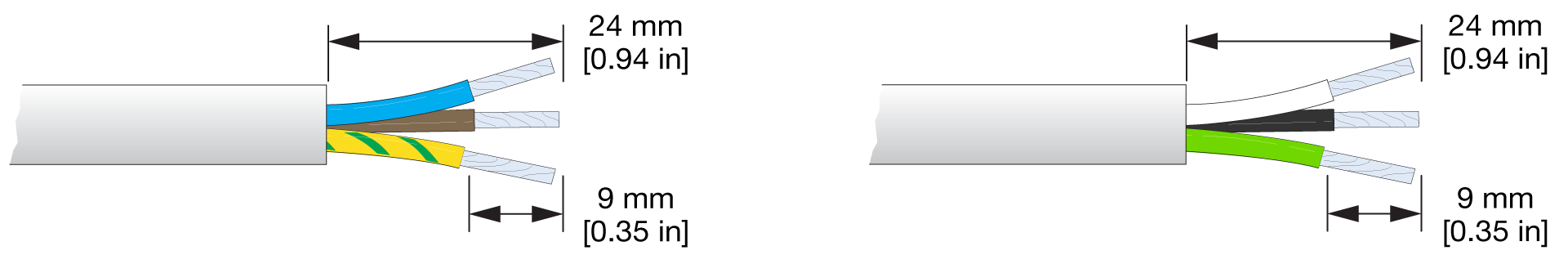
Strip the outer jacket (24 mm) and conductors (9 mm):
On the side of the insert, ensure all three T8 Torx screws are loose enough to allow the conductors to fully insert into the three terminals on the rear of the insert.
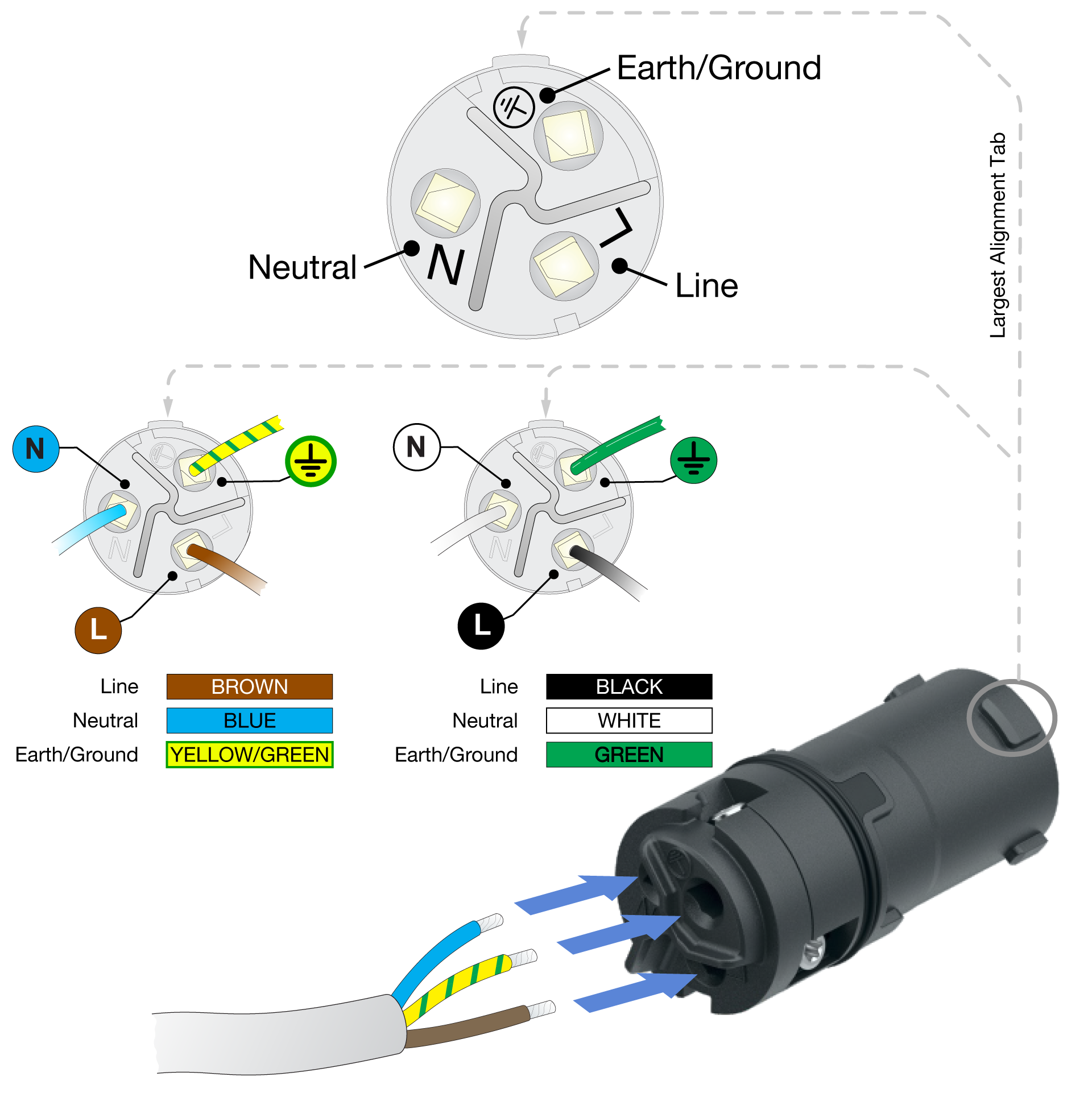
For each conductor: 1) match the insulation color to the correct terminal on the connector, 2) slide the stripped end of the conductor into the terminal, and 3) tighten the T8 Torx screw to 0.7 Nm (6.2 in/lb or 0.52 ft/lb) of torque.
Caution
After all the conductors are secured, always confirm the correct cable conductor is connected to the correct terminal of the connector insert.
Slide the chuck towards the insert. Align the two tabs on the chuck with the two alignment slots at the rear of the insert and mate the chuck to the insert. The two tabs on the chuck mate with the insert, quietly clicking when the chuck is secured.
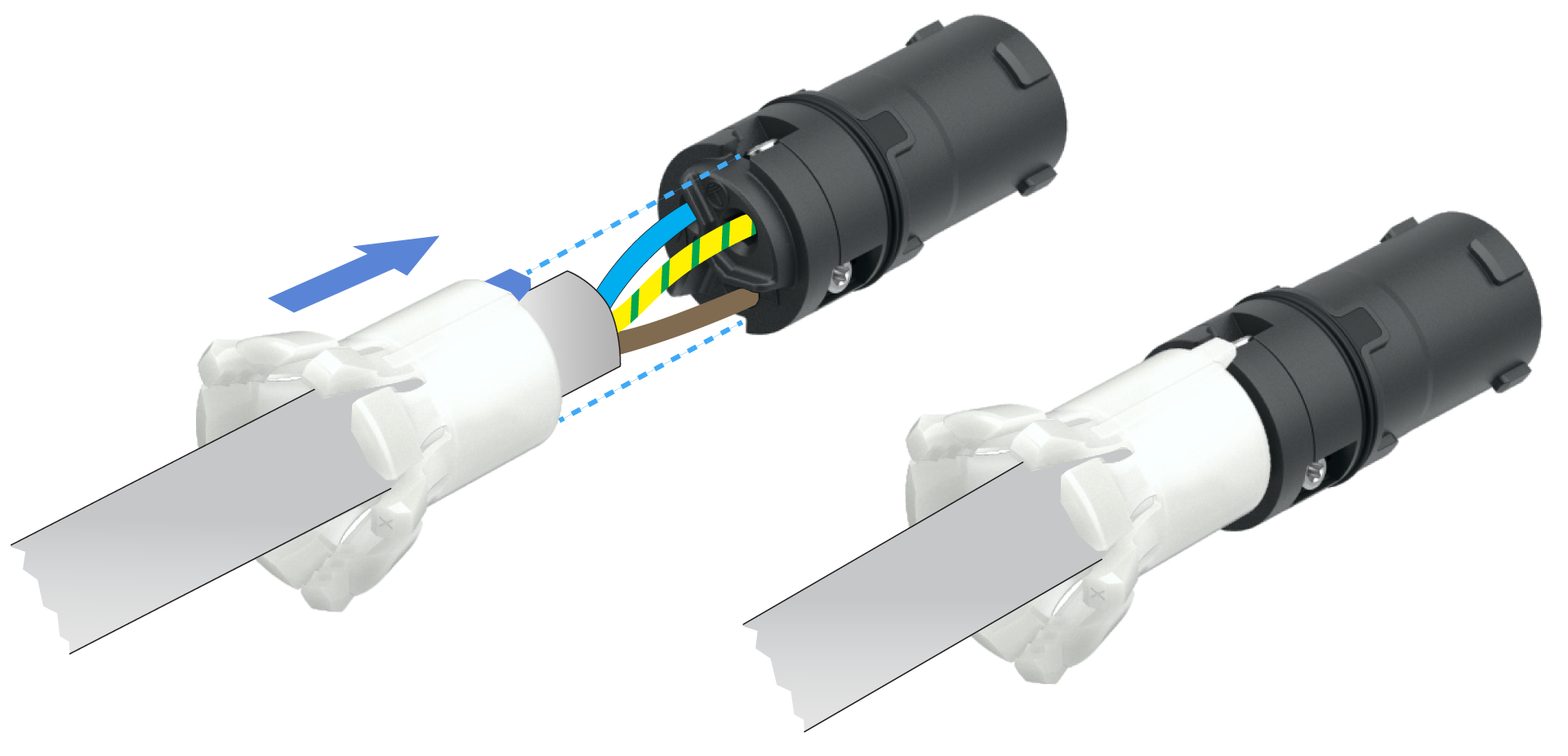
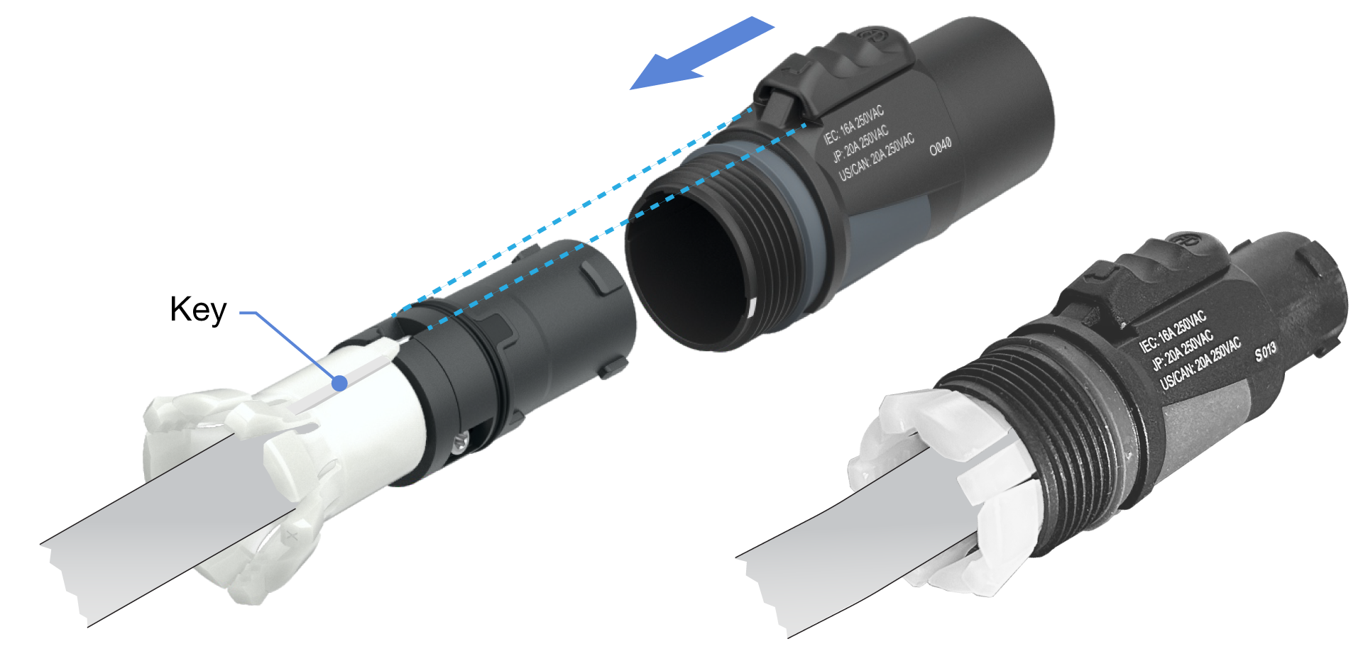
Slide the housing onto the insert, aligning the Earth/Ground conductor screw on the insert (highlighted) with the release latch on the housing (highlighted). This also aligns the small key on the chuck with a matching keyway inside the housing.
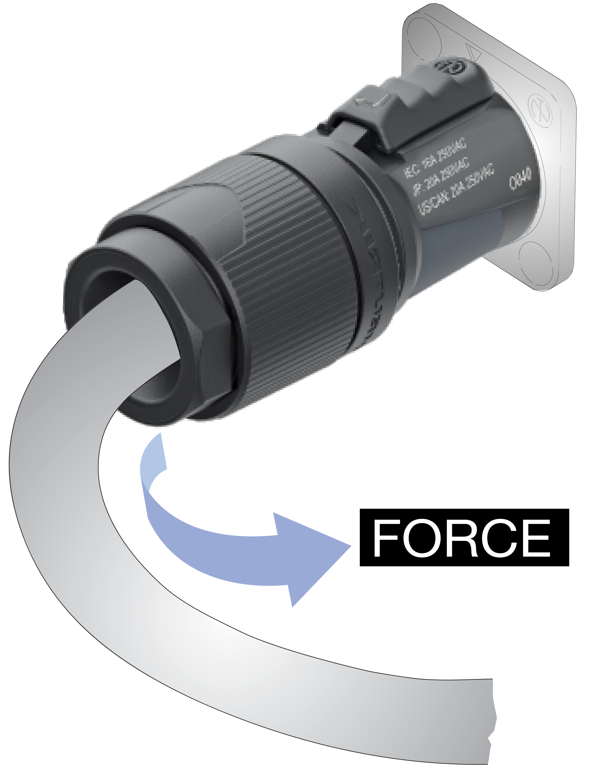
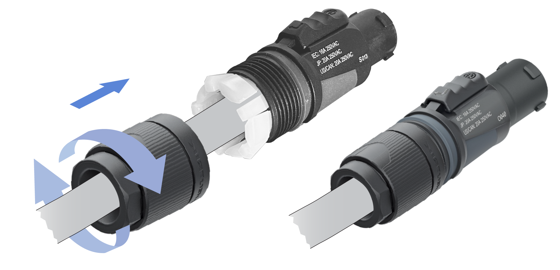
Slide the bushing over the chuck. Push and turn the bushing to thread it onto the housing.
Note
To meet safety standard requirements, accessing the cable entry requires a tool. As the bushing is tightened by hand, the bushing collar will begin to feel loose and will eventually spin. This is normal and expected.
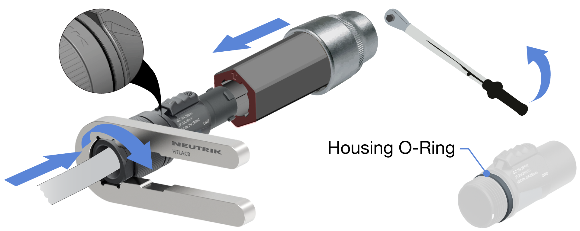
Slide the Neutrik tools onto the bushing and insert as shown. The insert tool accepts a 27 mm hex socket [1-1/8-inch]. Using a torque wrench, tighten the bushing to 2.5 Nm [22 in/lb, 1.8 lb/ft].
Caution
Damage can occur if another connector is used to secure the insert rather than the Neutrik tool.
Note
After tightening, make sure the bushing covers the 0-ring on the housing to achieve IP protection.
Unplug both ends of the cable.
Position the HTLACB tool on the bushing.
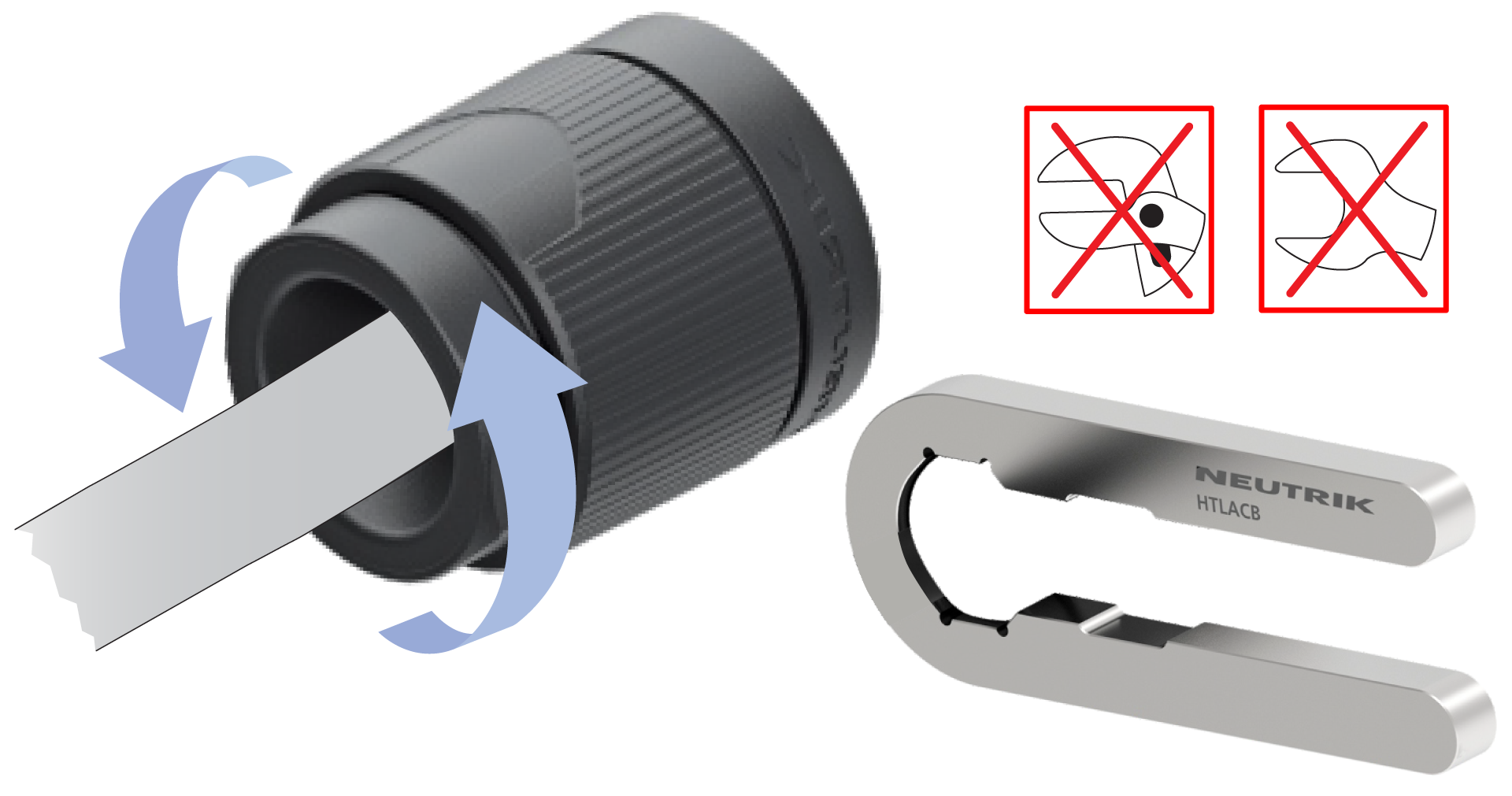
Loosen and remove the bushing.
Tip
If needed to secure the connector while loosening the bushing, slide the HTLACA tool onto the insert and grasp to retain.