Installation Guide — MLK-750 Upgrade Kit

The MG-MINA to 750-LFC upgrade kit converts existing MG-MINA MULTIPURPOSE GRIDS to accommodate flown 750-LFCs.
Note
As with any rigging assemblies, pay careful attention during assembly and follow the instructions exactly as described below. If at any time questions arise, contact Meyer Sound.
Upgrade kit (40.207.301.01) contents
Part number | description | Qty |
|---|---|---|
101.795 | SHOULDER SCREW, 1/4X7/8, 10-32, 17-4 PH | 2 |
109.521 | HEX NUT, 10-32, NYLOCK | 2 |
113.511 | FLAT WASHER, M6X18MM, 1.6MM THICK | 2 |
116.529 | CONICAL/ BELLEVILLE WASHER, .26"ID, .68"OD | 2 |
134.036 | LOCK PIN, 1/4"X0.90", BUTTON HEAD, 6" LANYARD | 2 |
61.207.302.01 | MG-MINA TO 750-LFC GRID LINK | 2 |
35.207.303.01 | MG-LINA/MINA/750-LFC LEFT LABEL FAB | 1 |
35.207.304.01 | MG-LINA/MINA/750-LFC RIGHT LABEL FAB | 1 |
35.207.305.01 | MG-LINA/MINA-750-LFC MINA/LINA RATING LABEL | 1 |
35.207.306.01 | MG-LINA/MINA-750-LFC 750-LFC RATING LABEL | 1 |
640.096 | MED STRENGTH, REMOVABLE, THREAD LOCKER, 0.5ML | 1 |
Required tools
#2 PHILLIPS SCREWDRIVER |
|---|
TORQUE WRENCH WITH A MINIMUM RANGE OF 14-24 IN-LBS [1.6-2.7 N-m] |
1/8” HEX KEY |
3/8” SOCKET HEAD FOR TORQUE WRENCH |
RAZOR BLADE |
ISOPROPYL ALCOHOL (IPA) AND WIPES |
Installation procedure
Remove the existing lanyard lock pin and tabs highlighted in FIGURE 1 with a Phillips head screwdriver. Place aside and save all screws and lanyard lock pins as these will be reinstalled later. Do this on both sides. Note: The lanyard wires have been removed in FIGURE 1 and FIGURE 5 for clarity.
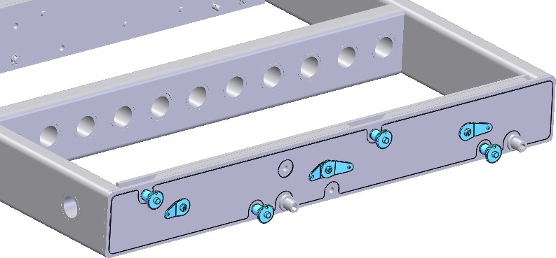
Figure 1
Remove existing grid labels highlighted in FIGURE 2, starting in one corner. If necessary, start the corner with a razor blade. Clean any residual reside with IPA. Do this on both sides. Note: The entirety of the existing labels does not need to be removed, as the new label will be applied over the existing label’s location.
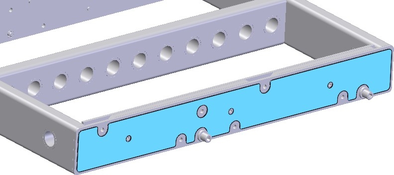
Figure 2
Install new grid labels, 35.207.303.01 and 35.207.304.01, where the existing labels were, as shown in FIGURE 3. Start by aligning several lanyard holes and adhere into place via a sliding motion. After the label is placed in the proper position, reapply firm pressure over the entire label to ensure good adhesion. Repeat on the opposite side. Use caution that the correct label is on the correct side - all label cutouts will have an exposed hole behind them.
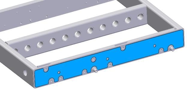
Figure 3
Install the 750-LFC grid link using the hardware shown in FIGURE 4. Note that the smaller diameter of the Bellville/ conical washer, 116.529, is to contact the screw head, 101.795, as shown below. Torque to 20-24 in-lbs [2.3-2.7 N-m]
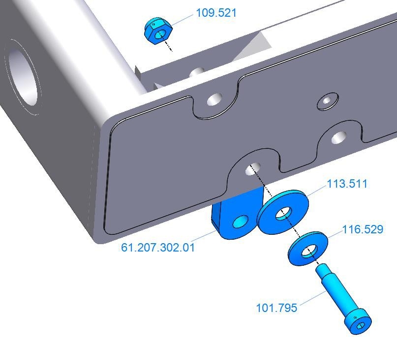
Figure 4
Reinstall lanyards removed in step 1, with the additional lanyard in this kit, 134.036, as shown in FIGURE 5. Add one drop of supplied thread locker (640.096) to each screw and torque to 14-18 in-lbs [1.6-2.0 N-m]. Note: Thread locker must be applied in ambient temperature above 50o F [10oC)
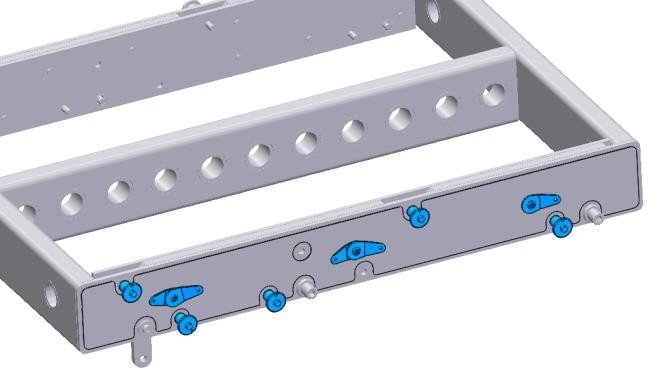
Figure 5
Install rating labels. Wipe down the inside of the grid with IPA where the rating labels will be installed. Remove backing and apply labels approximately where shown in FIGURE 6. Note: Their orientation is not important. Apply firm pressure to ensure good adhesion to the grid.

Figure 6