User Guide — Spacemap Go
Spatial sound design and mixing tool


Welcome to Meyer Sound Labs Spacemap Go User Guides! This guide provides information to set up and operate a Spacemap System using the Spacemap Go app.
User Guide — Spacemap Go
What is Spacemap Go?
Spacemap Go is a spatial sound design and mixing tool that leverages the audio processing capability of the Meyer Sound Galileo® GALAXY Network Platform to help sound artists create immersive audio experiences. Spacemap technology powers the world’s most sophisticated sound productions; now those same creative capabilities are available to a broad range of audio professionals in an intuitive iPad application.
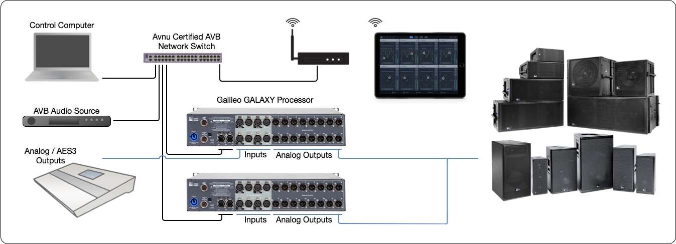
Example System – Hardware, Audio and Ethernet Connections
What are Spacemaps?
Spacemaps are two-dimensional graphic layouts that enable complex spatial sound distribution with easy-to-use controls. Trajectories are programmable sound paths applied to Spacemaps to dynamically change the output mix. Trajectories, which can be recorded, edited, reshaped, and even manipulated while playing, automate the movement of the Spacemap Panner, creating the illusion of sound movement. Two basic elements are key to building Spacemaps: nodes and trisets.
Nodes represent loudspeakers (Speaker Nodes), groups of loudspeakers (Virtual Nodes), or silence (Silent Nodes) and are arranged in groups of three as trisets. These trisets provide the panning elements of the Spacemap and guarantee smooth crossfades. As the channel’s Spacemap Panner moves closer to a node, more of the signal is routed to that node and less to the other two in the triset. Multiple adjacent trisets make up a Spacemap, creating customizable spatial contours. Audio from a specified set of Speaker Nodes can be automatically sent to designated outputs using Derived Nodes (for example, to send sound to subwoofers or an under-balcony loudspeaker).
Getting started
System requirements
Spacemap Systems include Galileo GALAXY processors, an Ethernet network, loudspeakers, and an iPad running the Spacemap Go app or third-party controllers. Systems with multiple processors require an Avnu-certified network switch.

Example System – Hardware, Audio and Ethernet Connections
Compass | Compass GO | GALAXY Firmware | Spacemap Go app |
|---|---|---|---|
4.9.2 | 2.8.3 | 2.4.2 | 1.2.0 |
4.9.1 | 2.8.2 | 2.4.1 | 1.1.0 |
4.9.0 | 2.8.1 | 2.4.0 | 1.0.1 |
iPad
An Apple iPad with iPadOS 14 or later.
Multiple iPads running Spacemap Go can be used with a system to:
Enable multiple system operators
Display different app views for a system operator
Control instances requiring simultaneous cue recall and Spacemap control
Note
iOS 15 privacy settings need to be enabled for Compass GO and Spacemap Go apps. When enabled, these apps can discover GALAXY processors on the network. On the iPad, go to Settings > Privacy > Local Network and allow the apps access for Compass Go and Spacemap Go.
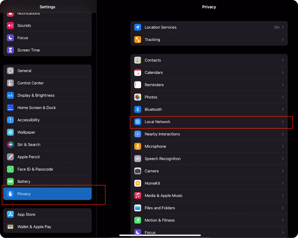
iOS 15 Privacy Settings to Allow Discovery of GALAXY Processors
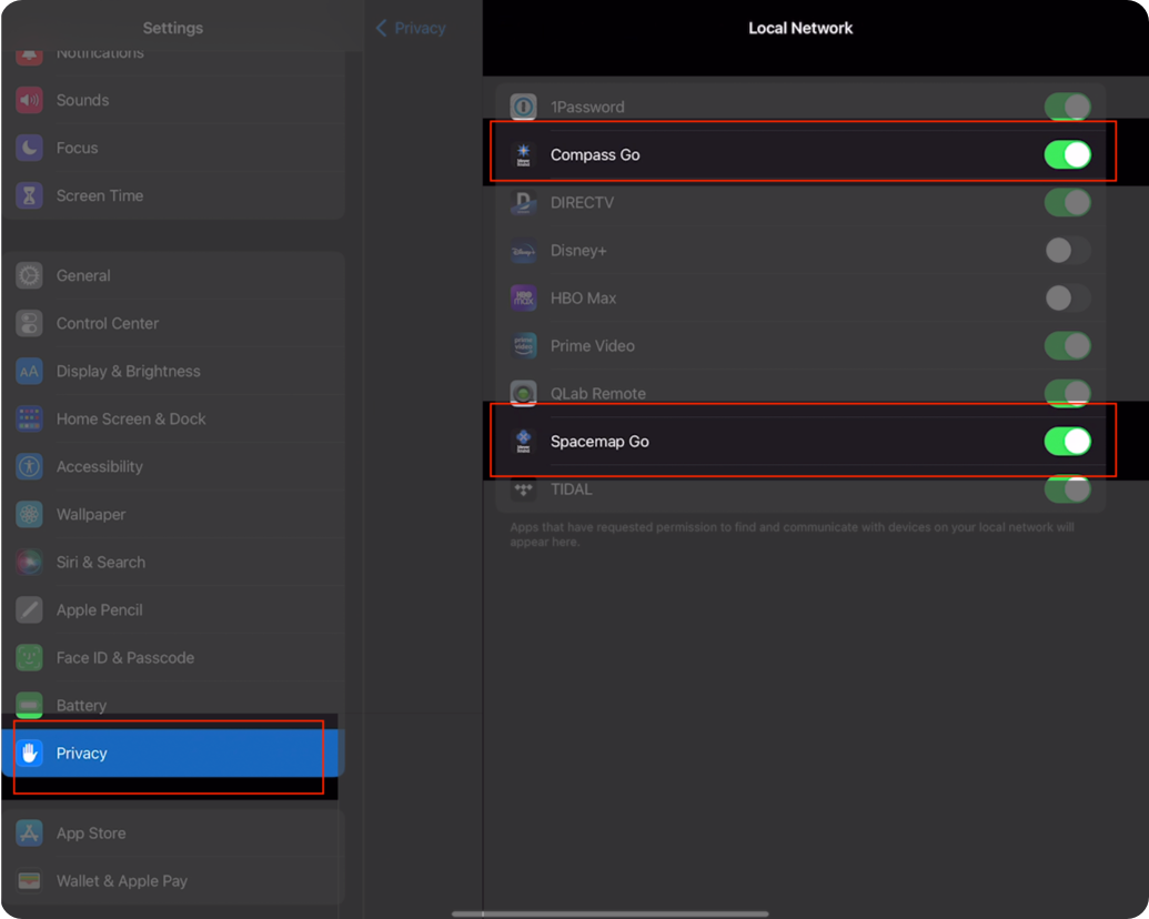
iOS 15 Privacy Settings to Allow Discovery of GALAXY Processors
Spacemap Go app
The Spacemap Go iPad app is available from the Apple App Store at no cost. Visit the App Store from the iPad to install.
Galileo GALAXY processor(s)
Galileo GALAXY processors are used in a Spacemap System. Each system supports up to 32 inputs and 256 outputs, depending on the number of processors and audio input format(s). Any of the GALAXY models can be used, except the GALAXY Bluehorn 816. Firmware that includes the Spacemap Mode boot option is required.
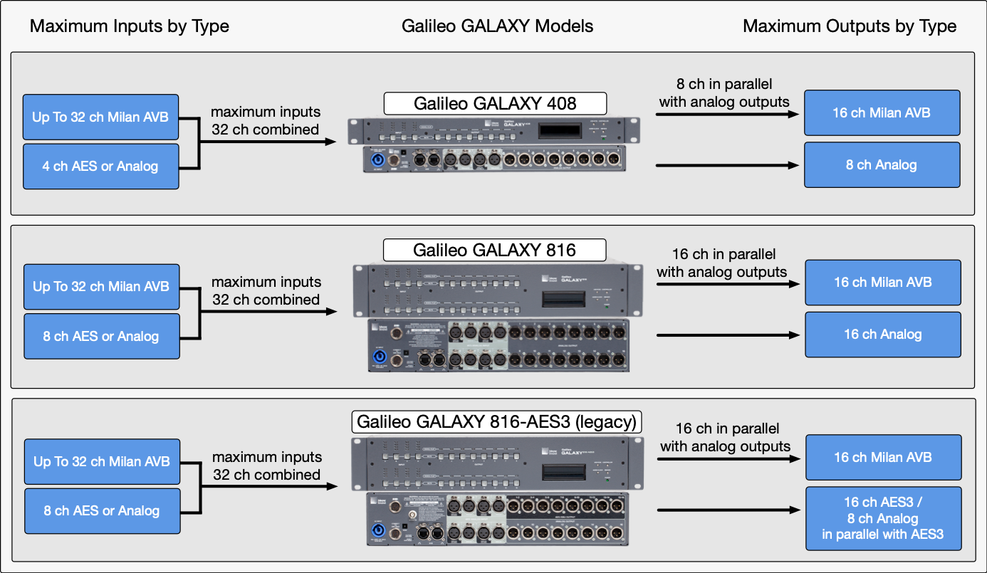
Galileo GALAXY Processor Models – Maximum Number of Inputs and Outputs by Model
Spacemap Go system inputs
The maximum number of Spacemap System inputs is 32, whether one or sixteen processors are used. The system inputs can be analog, AES3, or Milan AVB—usually transmitted by a mixing console, playback device, or an AVB source. See the Spacemap System Audio Signals section on the Operations page for further explanation.
Maximum number of inputs by processor model:
GALAXY 408: 32 channels total, 4 channels can be AES3 or analog XLR inputs, reducing the maximum of 32 Milan AVB inputs
GALAXY 816: 32 channels total, 8 channels can be AES3 or analog XLR inputs, reducing the maximum of 32 Milan AVB inputs
GALAXY 816AES (legacy): 32 channels total, 8 channels can be AES3 or analog XLR inputs, reducing the maximum of 32 Milan AVB inputs
All GALAXY processor models support up to 32 Milan AVB inputs, with input processing available for inputs A-H (8 channels). Milan AVB inputs 9-32 are routed directly to the matrix inputs.
The GALAXY processors comply, and are certified by the Avnu Alliance as Milan compliant:
“Every device will connect with any other device using a variety of agreed-upon formats and market-required definitions in the protocol. Milan adds essential agreements about the implementation of AVB technology, including requirements for compatible and compliant media formats, media-clocking, redundancy, and controller software, while ensuring those requirements are implemented correctly through compliance testing and certification of end devices.” -Avnu Alliance
The stream format GALAXY processors use is: AAF-PCM 24-bit in 32 integer, 8-channels of 12 samples at 96kHz or 48kHz.
AVB inputs from devices that are not Milan certified, may establish stream connections and transport audio successfully. However, these connections may not:
Successfully re-establish after power cycling equipment (persistent connection)
May not support the Milan network redundancy schemes
May not maintain clocking between devices
For these reasons, we do not recommend using AVB input sources that are not Milan certified for show critical applications. Certification guarantees functionality, because all certified devices are rigorously tested for inter-connectivity and reliability. We cannot ensure the functionality of non-certified devices and we encourage users to contact the device manufacturer to inquire about their certification status, and how to make AVB connections to GALAXY processors.
Spacemap Go system outputs
The maximum total number of Spacemap System outputs is 256. The outputs are usually connected directly to self-powered loudspeakers, which typically have analog inputs. See the Spacemap System Audio Signals section on the Operations page for further explanation.
Milan AVB outputs are in parallel with the analog or AES3 outputs.
Maximum number of outputs by processor model:
GALAXY 408: 8 analog XLR outputs, 16 Milan AVB outputs
GALAXY 816: 16 analog XLR outputs, 16 Milan AVB outputs
GALAXY 816AES (legacy): 16 AES3 channels / 8 XLR connectors , 8 analog XLR outputs (in parallel with output channels 9-16), 16 Milan AVB outputs
Compass control software
The current version of Compass software is needed. The GALAXY firmware included with this and future releases supports GALAXY Spacemap Mode. Compass also supports virtual GALAXY processors booted to Spacemap Mode, enabling off-line configuration and programing.
Ethernet network
A network connection between the iPad(s) and the GALAXY processor(s) is needed for control. The connection can be wireless or wired. For control-only networks, Avnu Alliance certified network switches are not required. Currently, IPv6 is used for network connectivity between the Spacemap Go app on an iPad and GALAXY processors. Please ensure the wireless access point and the network switch are IPv6 enabled. The connection between a computer and a single Galileo GALAXY does not require a network switch.
If the system inputs are sent via Milan AVB, or if more than one GALAXY processor is used in a system, an Avnu-certified AVB network switch connects the GALAXY processors and optional AVB sources. For the latest list of Avnu-certified hardware, including switches, visit the Avnu Alliance website. Note that network switches certified as AVB compliant meet the Avnu Milan specification. No network switches are certified as Milan AVB compliant.
Milan AVB sources
Avnu-certified Milan AVB devices are fully supported. For a list of devices, see Avnu's Certified Product Registry list.
Non-certified devices may successfully connect. These devices may require additional configuration and may not be capable of establishing or re-establishing a persistent, error-free connection during normal operation and/or power cycling. Meyer Sound is working with other manufactures to make interoperability advancements.
Hardware connections
Both Ethernet network and audio signal connections are necessary to create an operational Spacemap Go system. The Ethernet connections are for system control, Milan AVB audio transport between processors, and optional Milan AVB inputs. Analog and AES3 audio signal inputs are connected to the Galileo GALAXY processor(s). The processor outputs are connected to loudspeakers or other audio devices. The Spacemap Go app is used to configure the inputs and outputs of the system.
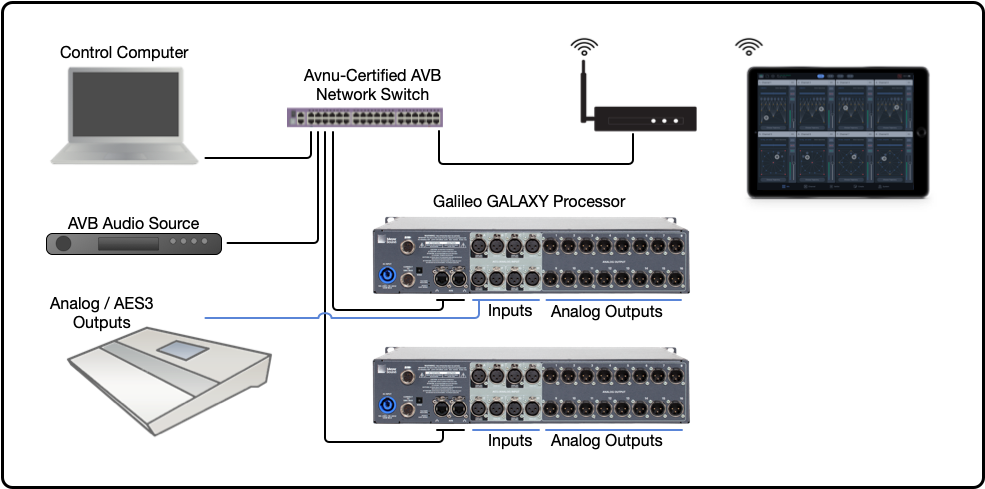
Example Ethernet and Audio Connections
Audio input/output configurations
Source audio signals are connected to the Galileo GALAXY processor XLR inputs or via the RJ-45 connectors for Milan AVB audio streams.
Galileo GALAXY audio inputs
The iPad app Spacemap Go includes a connection wizard that configures the inputs and outputs of the GALAXY processors. For systems that include multiple processors, the wizard also configures the Milan AVB transport used to share input signals across the system processors. The configuration wizard assumes the first input is connected to input A and that additional inputs are contiguous.
Analog: make connections starting with Input A, then Input B, C, D, E, and FAES3: make connections starting with Input A, then Input C, E, and G
AES3: make connections starting with Input A, then Input C, E, and G
Milan AVB: Any processor input can be selected to receive a Milan AVB stream. Matrix Inputs 9–32 of the GALAXY 816 models and Matrix Inputs 5–32 of the GALAXY 408 model are only used for Milan AVB inputs.
The AVB input stream format GALAXY processors accept is: AAF-PCM 24-bit in 32 integer, 8-channels of 12 samples at 96kHz or 48kHz.
AVB inputs from devices that are not Milan certified, may establish stream connections and transport audio successfully. However, these connections may not:
Successfully re-establish connection after power cycling equipment (persistent connection)
May not support the Milan network redundancy schemes
May not maintain clocking between devices
For these reasons, we do not recommend using AVB input sources that are not Milan certified for show critical applications. Certification guarantees functionality, as all certified devices are rigorously tested for inter-connectivity and reliability. We cannot ensure the functionality of non-certified devices and encourage users to contact those device manufacturers, inquire about their certification status and how to make stable, persistent AVB connections to GALAXY processors.
See the Galileo GALAXY User Guide for further information about inputs and outputs.
Galileo GALAXY audio outputs to loudspeakers
Analog and AES3: The outputs of Galileo GALAXY processors are analog, except for the 816AES model (legacy), which has 16 AES3 output channels available on XLR connectors 1–8, with analog copies of Outputs 9–16 available on XLR connectors 9–16. The outputs are typically connected directly to self-powered loudspeakers.
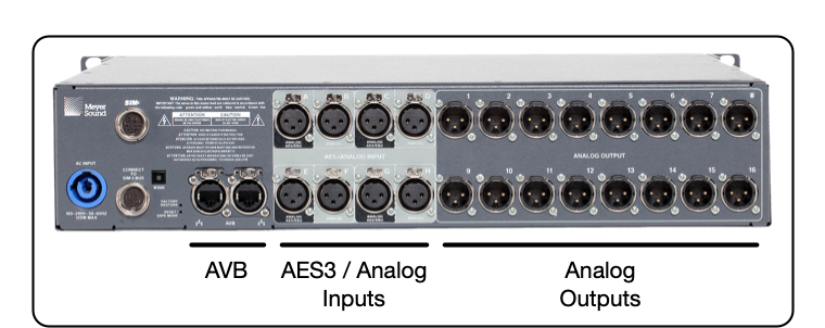
GALAXY 816 Audio Connections
Milan AVB: All GALAXY models have 16 outputs that are available as Milan AVB outputs. The output stream format is Milan compliant, AAF, 8-channel streams. Both 96 kHz and 48 kHz sample rate streams are available, Stream Output 0, 1, 4, and 5 below.
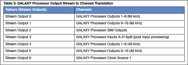
GALAXY Milan AVB Output Streams
See the Galileo GALAXY User Guide for further information about inputs and outputs.
Network connections
Both the iPad and Galileo GALAXY processors must be connected to the same Ethernet network for control during system operation. iPad connections can be wireless. During processor configuration, a computer running Compass software is also connected to this network.
Ethernet
IPv6 is used for network connectivity between the Spacemap Go app on an iPad and GALAXY processors. Please ensure the wireless access point and the network switch are IPv6 enabled. The connection between a computer and a single Galileo GALAXY does not require a network switch.
Each GALAXY processor has two RJ-45 Ethernet connectors used for network connectivity and support a variety of redundant network schemes. Download the Galileo GALAXY User Guide for details.
When facing the rear of a processor, make primary network connections using Ethernet Port 1 (left connector) for standardization. Use Ethernet Port 2 (right connector) for connection to a redundant network. The ports are identical in function, sending and receiving different types of data. Compass, Compass GO, Spacemap Go, and devices that send and receive OSC commands are used to make changes to the processor settings. These ports also send and receive Milan AVB audio streams.
The two ports have different network speed capabilities:
Port 1 (left) is capable of both 1000bT and 100bT connections
Port 2 (right) is 1000bT, or Gigabit Ethernet only
Devices capable of 100bT connections can only be connected to Port 1 for proper functionality. Many older or less functional network switches and access points (WiFi) are capable of only 100bT connections.
When using more than one GALAXY processor in a Spacemap Go system or when the system input source format is Milan AVB, an Avnu Alliance certified network switch is needed. Avnu-certified network switches are specialized switches, capable of supporting the underlying Milan AVB protocols and that have been certified for interoperability. Extreme network switch configuration instructions are available here. Generic network switches do not support Milan AVB audio streams but can be used for “control only” networks.
When GALAXY processors are booted into Spacemap Mode, the inputs of the processors are shared with the other processors over the Ethernet network using the Milan AVB protocol.
System example: 1
Analog or AES3 audio inputs are connected to the GALAXY input XLR connectors.
A wireless access point (WiFi) is connected to GALAXY Ethernet Port 1.
An iPad running Spacemap Go is connected via wireless Ethernet (Wi-Fi) to the wireless access point.
GALAXY processor analog XLR outputs are connected to loudspeakers (not shown below).
Note
An Avnu-certified network switch is not needed for this system because the network is not transporting any AVB streams. It is only used for control.

Example System – Analog/AES3 Inputs, Galileo GALAXY Processor, Wi-Fi Access Point, and an iPad (Loudspeakers Not Shown)
System example: 2
This example uses Milan AVB signal inputs and requires an Avnu Alliance certified AVB network switch. The source audio is sent via Milan AVB to the Galileo GALAXY.
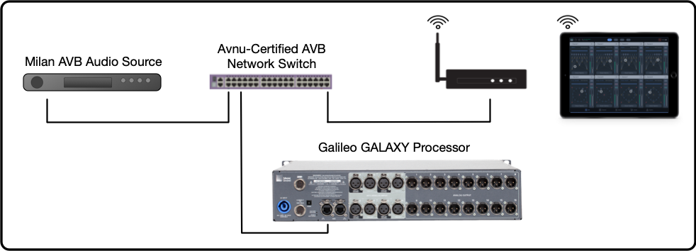
System Example Two: Milan AVB Audio Input and Analog Output
System example: 3
This example uses two GALAXY processors. The Milan AVB digital audio protocol is used to share the analog/AES3 inputs with the second processor. An Avnu Alliance-certified network switch is needed. The GALAXY XLR outputs or the Milan AVB output streams can be used to connect to loudspeakers or other Milan AVB devices connected to the network switch.
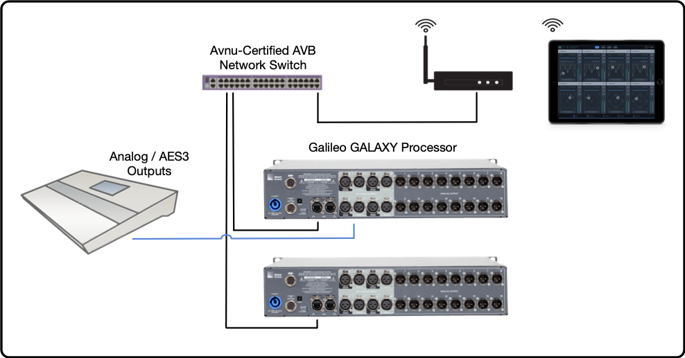
Example 3: Two Processors Used, Requires Avnu Certified Switch
AVB Milan network redundancy
A secondary/redundant network can be connected in case the primary network experiences an issue, which ensures continuous Milan AVB transport and system control connection.
AVB clock considerations
The connections of the AVB media clock will be automatically set when the Spacemap Go system configuration is completed.
Configure GALAXY processors
The steps listed below assume that the audio and network connection instructions have been completed.
Select one of the three possible scenarios listed below for the appropriate configuration steps:
Configure Galileo GALAXY Hardware – New Processor
The “New Steps” below overwrite all the processor settings and stored Snapshots. Follow these steps to upload new firmware and reboot Galileo GALAXY processors to Spacemap Mode.
Configure Galileo GALAXY Hardware – In-Use Processor
The “Use Steps” below preserve the settings of the input and output processing of Galileo GALAXY processors (EQ, delay, gain adjustments, etc.) by storing and recalling a GALAXY Snapshot before and after recalling factory defaults. The matrix levels will later be overwritten by Spacemap Go. Make any necessary Output Channel Gain adjustments to compensate.
Configure Virtual Galileo GALAXY
If Galileo GALAXY hardware is not available, Compass can create virtual processors. All the functions of Spacemap Go are available without passing audio signals. Using virtual processors facilitates learning, testing, and programming off-line.
AVB connection management
Compass software manages the AVB connections of GALAXY processors in Normal Mode. Spacemap Go manages AVB connections of processors in Spacemap Mode.
Entity and group names
Each AVB device has an Entity Name, a human-readable identification of a specific AVB device. Use unique Entity Names for each GALAXY processor and all other AVB devices.
Each AVB device also has a Group Name, a human-readable label that is used to group devices for control.
Important
When a GALAXY processor is in Spacemap Mode, Spacemap Go manages the AVB connections of all GALAXY processors that have the same Group Name, even if some processors are in Normal Mode. Use a different Group Name for Normal Mode processors, allowing AVB connection management using Compass software. AVB connections for the Normal Mode processor are not possible until the Group Name is changed to one that does not include a processor in Spacemap Mode.
Configure a new GALAXY processor
The following procedure updates the GALAXY processor firmware and boots the processor(s) to Spacemap Mode.
Tip
Compass software includes an option to update all connected processors simultaneously. When configuring multiple processors, it is more efficient to connect the processors and the Compass computer to a standard or Avnu-certified network switch.
Power on the network switch (if used), Wi-Fi access point, and all GALAXY processors
Download, install, and launch the current version of Compass software (4.8 or later).
Select the PROCESSORS > INVENTORY
Click CONNECT for each processor used in the Spacemap System. Click through the firmware warning message.

Compass Software – Inventory Tab, Click Connect and Firmware Mismatch Warning
Select the tab related to the first processor.
Select the SETTINGS > NETWORK tab.
Click the REBOOT WITH FACTORY DEFAULTS button.
Repeat Step 7 for each processor.
Note
The processor(s) will disconnect from Compass while rebooting (about 45 seconds) and then reconnect.
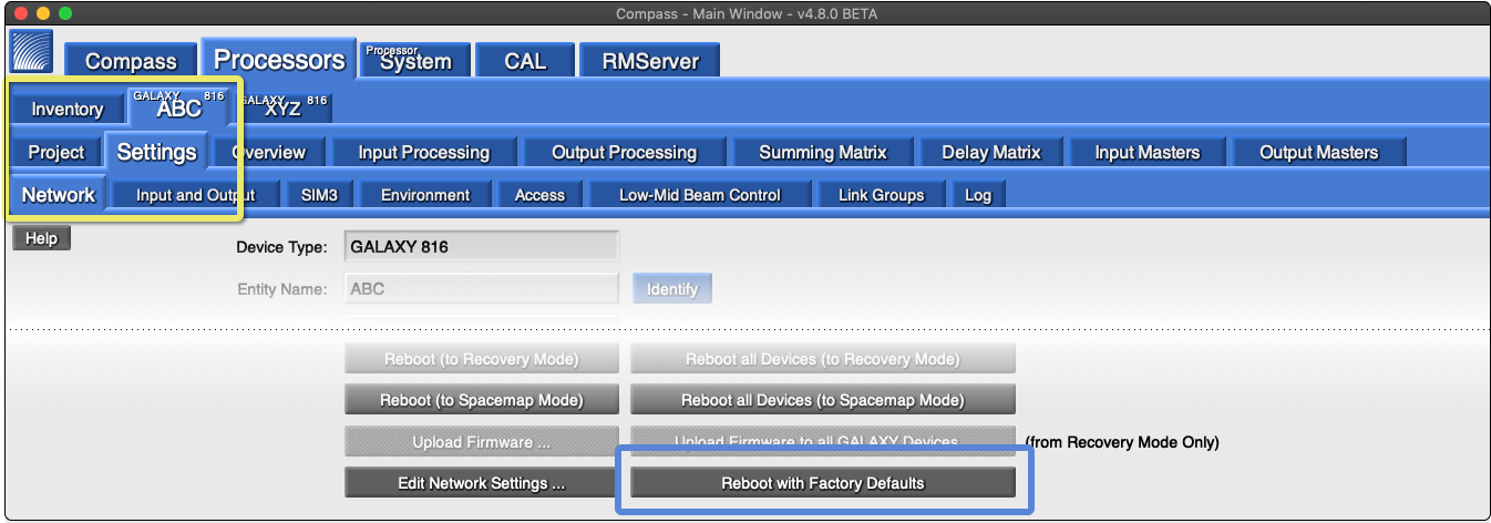
Compass Software – Network Tab, Click Reboot with Factory Defaults
Enter an Entity Name—unique for each processor (e.g., SMG-1, SMG-2…).
Enter a Group Name—use an identical name for all processors of a Spacemap System (e.g., show or venue name).
Repeat Steps 8 and 9 for each processor.
Note
All processors require the same Group Name to be recognized as part of a Spacemap System.
The Entity and Group Names cannot be changed after the processor is booted to Spacemap Mode.
Multiple Spacemap Systems can be created by using a different Group Name for the processors of additional system(s).
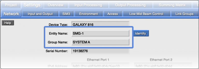
Compass Software – Network Tab, Enter Entity Name (Unique) and Group Name (Identical for All Processors)
Click the REBOOT ALL DEVICES (TO RECOVERY MODE) button.
Note
The processor(s) will disconnect from Compass while rebooting (about 30 seconds) and then reconnect in Recovery Mode.

Compass Software – Reboot to Recovery Mode
Click the UPLOAD FIRMWARE TO ALL GALAXY DEVICES button.

Compass Software – Upload Firmware to all GALAXY Devices
Select the
.galaxyFirmwarefile included with the Compass software. The firmware version will be newer than the illustration below.Default Compass installation directories:
MacOS: /Applications/Compass > <current version>/Win: /Program Files (x86)/Meyer Sound/Compass <current version>/
Note
The processor(s) will disconnect from Compass while rebooting (about 30 seconds) and then reconnect.
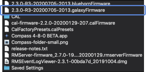
MacOS Finder – Compass Directory Files, GALAXY firmware file
Click OPEN to start uploading the firmware.
Note
The processor(s) will disconnect from Compass during the upload and reboot process (about three minutes) and then reconnect in Normal Mode.
Click the REBOOT ALL DEVICES (TO SPACEMAP MODE) button.
Note
The processor(s) will disconnect from Compass while rebooting (about 30 seconds) and then reconnect.

Compass Software – Reboot to Spacemap Mode
Compass indicates that a processor is in Spacemap Mode by changing the color of the processor tab.

Compass Software – Tab Color Indicates Spacemap Mode
Configure a GALAXY processor that's in use
Follow these steps to save existing input/output processing settings, upload firmware and reboot Galileo GALAXY processors to Spacemap Mode. The saved processor settings will be recalled during the procedure.
Power on the network switch (if used) and all GALAXY processors.
Launch the currently used version of Compass software.
Click the PROCESSORS > INVENTORY tab.
Note
Processors should be auto-discovered and listed. If not, click the FIND DEVICES button.
Click CONNECT for each processor used in a Spacemap System.

Compass Software – Click CONNECT for Each Processor
Select SHOW GLOBAL SNAPSHOT FEATURES, upper-right.
Click GLOBAL SNAPSHOT OPTIONS button, lower-right.

Compass Software – Inventory Tab, Show Global Project Settings and Global Snapshot Options
Click CREATE NEW in the pop-up dialog.
Enter the Snapshot name: SMG MIGRATION; click OK and CLOSE.
Note
This step creates a Snapshot in each GALAXY named SMG MIGRATION, which is recalled later and then saved by the Spacemap Go app as a Spacemap System Snapshot.

Compass Software – Global Snapshot Options, Create New, Enter Snapshot Name
Click the Global Project SAVE AS button.
Select a directory/folder and enter the file name: SMG MIGRATION; click SAVE.
Note
This step saves a Global Project on the computer as a backup

Compass Software – Save As Global Project
Close the older version of Compass.
Download, install, and launch the current version of Compass software (version 4.8 or later).
Click the PROCESSORS > INVENTORY tab.
Note
Processors should be auto-discovered and listed. If not, click FIND DEVICES.
Click CONNECT for each processor used in a Spacemap System, then YES for the firmware mismatch warning.

Compass Software – Inventory Tab, Click Connect and Acknowledge Firmware Mismatch
Select the tab related to the first processor.
Select the SETTINGS > NETWORK tab.
Click the REBOOT WITH FACTORY DEFAULTS button.
Repeat Step 17 for each processor.
Note
The processor(s) will disconnect from Compass while rebooting (about 45 seconds) and then reconnect.
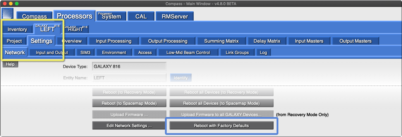
Compass Software – Network Tab, Reboot with Factory Defaults
Enter an Entity Name—unique for each processor (e.g., SMG-1, SMG-2…).
Enter a Group Name—use an identical name for all processors of a Spacemap System (e.g., show or venue name).
Repeat Step 18 and 19 for each processor.
Note
All processors require the same Group Name to be recognized as part of a Spacemap System.
The Entity and Group Names cannot be changed after the processor is booted to Spacemap Mode.
Multiple Spacemap Systems can be created by using a different Group Name for the processors of additional system(s).
Click the REBOOT ALL DEVICES (TO RECOVERY MODE) button.
Note
The processor will disconnect from Compass during the upload period (about 30 seconds) and then reconnect.

Compass Software – Reboot to Recovery Mode
Click the UPLOAD FIRMWARE TO ALL GALAXY DEVICES button.

Compass Software – Upload Firmware to all GALAXY Devices
Select the
.galaxyFirmwarefile included with the Compass software. The firmware version will be newer than illustrated below.Click OPEN to start uploading the firmware.
Note
The processor(s) will disconnect from Compass during the upload/reboot (about three minutes) and then reconnect.

MacOS Finder – Compass Directory Files, GALAXY firmware file
Click the REBOOT ALL DEVICES (TO SPACEMAP MODE) button.
Note
The processor(s) will disconnect from Compass while rebooting (about 30 seconds) and then reconnect.

Compass Software – Reboot All Devices to Spacemap Mode
Compass indicates that a processor is in Spacemap Mode by changing the color of the processor tab.

Compass Software – Tab Color Indicates Spacemap Mode
Configure a virtual GALAXY processor
If Galileo GALAXY hardware is not available, Compass can create virtual processors. All the functions of Spacemap Go are available without passing audio signals. Using virtual processors facilitates learning, testing, and programming off-line.
Quick start example configuration
Follow the steps in this example to quickly configure the Spacemap Go system and pass audio.
Prerequisites:
This quick start example configuration assumes that the audio and network connection instructions and one of the Galileo GALAXY processor configuration methods have been successfully completed.
Step 1: Configure system inputs and outputs
This quick start example configuration uses the Spacemap Go app to define the inputs and outputs of a Spacemap Go system, including:
Inputs: 2 analog, 2 AES3, and 28 Milan AVB channels from an AVB source
Outputs: 16 analog channels
Processors: one GALAXY 816
Network switch: one Milan AVB, Avnu Alliance certified network switch with the AVB license pack installed and configured
Step 2: Set up a quick start example configuration
Note
Ensure the GALAXY processors are booted to Spacemap Mode and the Group Names of each processor are identical.
Power off or disconnect loudspeakers from the GALAXY processor.
Caution
This step prevents the possibility of inadvertently reproducing very loud sounds. After the system is configured, the loudspeakers are powered on or reconnected.
Connect the iPad to a Wi-Fi network connected to the Internet
Install the Spacemap Go app on an iPad. The app is available at no cost from the Apple App Store.
Connect the iPad to the Spacemap Go Wi-Fi network.
Launch the Spacemap Go app.
Note
When Spacemap Go launches, the Group Name assigned to all of the processors is displayed as an available Spacemap System.
Tap a Spacemap Go System Name.
For this example: tap SYSTEM A
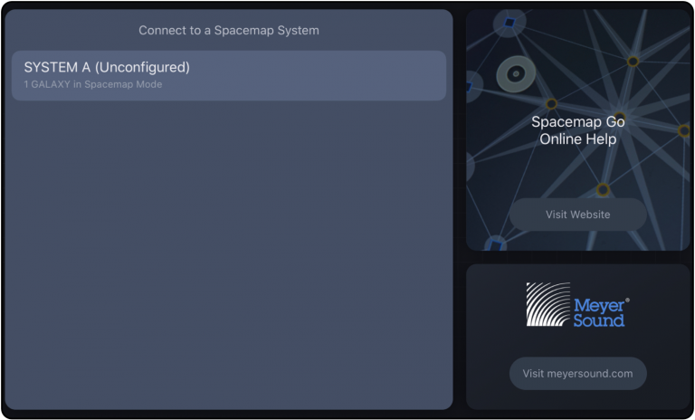
Connection Wizard – Tap a Spacemap System to Connect
If a system has no physical audio inputs (AVB only), tap PROCEED and go to Step 10.
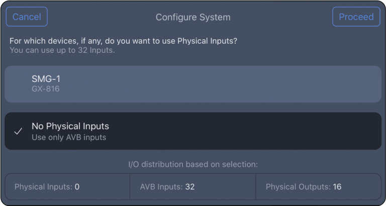
Spacemap Go – No Physical Inputs
Tap the GALAXY processor(s) with physical audio inputs (analog or AES3).
Select Analog or AES3, then tap
 buttons to adjust the total number of analog plus AES3 inputs for each processor; tap PROCEED.
Note
If inputs for a processor are both analog and AES3, individual signal types are selected later.
For this example, tap SMG-1 and set Physical Inputs to 4.
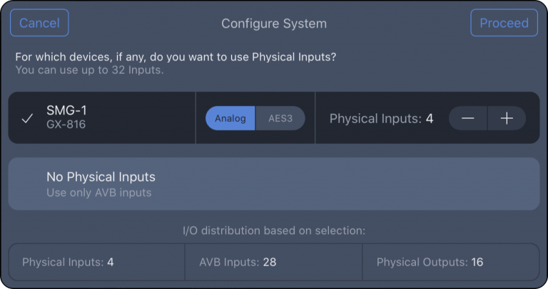
Use the
 buttons to adjust the number of AVB inputs used for the system (0–32 selectable). If the system only shares analog or AES inputs, set the AVB Inputs to “0.” Tap SAVE TO SYSTEM.
For this example, 28 AVB inputs are used:
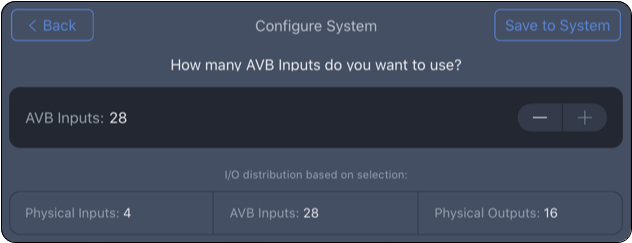
Configure System – Select Number of AVB Inputs
Tap CONNECT AVB.
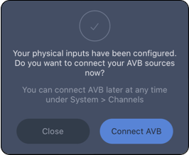
Spacemap Go App, Connect AVB Sources
Select Analog or AES3 for individual inputs, tap UPDATE SYSTEM and confirm.
For this example: Inputs 1 and 2 are analog, Inputs 3 and 4 are AES3.
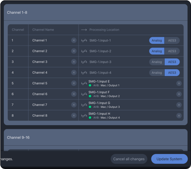
Spacemap Go – Input Type Selections for Analog and AES3
If the GALAXY processor is in-use and the settings need to be preserved, continue to the next Step 3 (optional): Keep GALAXY settings when using an in-use processor.
If this is a new processor and the GALAXY processor settings do not need to be preserved, continue on to Step 4: Create a mix snapshot.
Step 3 (optional): Keep GALAXY settings when using an in-use processor
From the GALAXY Configuration procedure, if a processor is part of a system that is in use, the optimization settings were stored as a Global Snapshot in Compass. This is the appropriate time to recall that Global Snapshot and save the settings to a Spacemap Go System Snapshot.
Using Compass software, from the INVENTORY tab, click the OPEN button (lower-right) to open the Global Project created earlier.
Select the SMG MIGRATION Global Project file; click OPEN.
Click the GLOBAL SNAPSHOT OPTIONS button.
Select SMG MIGRATION Global Snapshot; click RECALL.
Exit the Compass software. It is not used beyond this step.
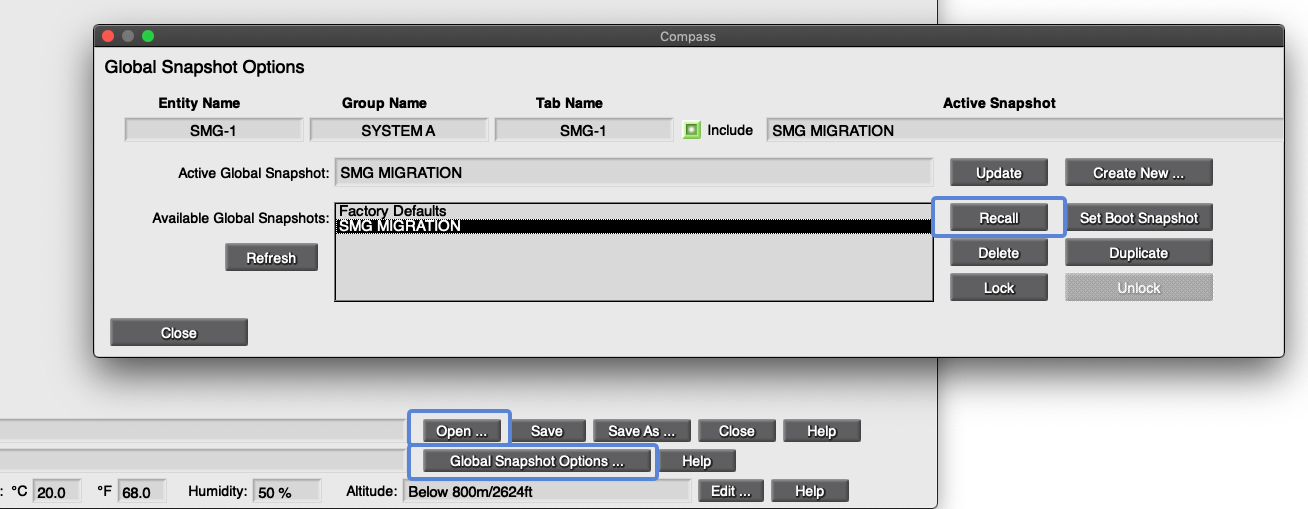
Compass Software – Open Global Project, Recall Global Project
In Spacemap Go, tap SETTINGS VEIW, tap INPUTS and RECONFIGURE INPUTS.
Make physical and AVB input selections again and tap SAVE TO SYSTEM.
In Spacemap Go, tap
 , SYSTEM SNAPSHOTS. Tap More (three-dot icon) next to User System Defaults and select UPDATE SYSTEM DEFAULT SNAPSHOT.
Note
This step captures processor optimization settings. The System Default Snapshot is automatically recalled when app is started.

Spacemap Go, Project Settings – Update User Default Snapshot
Tap
 , and then tap SAVE PROJECT.
Select Save to File… and/or Save to GALAXY, tap PROCEED.
iPadOS: select SAVE TO FILES.
Add a new folder or select the Spacemap Go folder.
Tap the file name to edit it.
Tap SAVE.
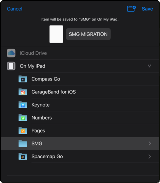
iPadOS – Save Spacemap Go Project File
Step 4: Create a mix snapshot
Tap the SETLIST view.
Tap Demo 1–8.
Tap RECALL to confirm.
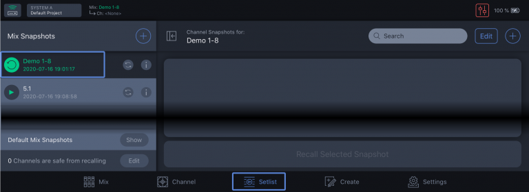
Spacemap Go – Setlist View, Select Demo 1-8
Tap
 to create new Mix Snapshot.
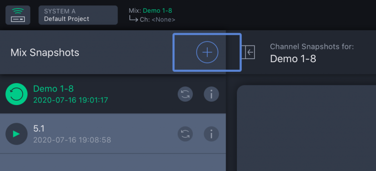
Spacemap Go – Add New Mix Snapshot
Enter
My First Mix Snapshot, tap CAPTURE.
Step 5: Check inputs and adjust levels
Click
 and set the MIX LEVEL fader to -40 dB.
Caution
This step prevents very loud sounds from being reproduced by the loudspeakers when audio is passed. There is also a MUTE button available.
Note
Tap drag the fader or tap the numeric value and enter a value.
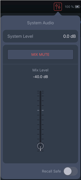
Spacemap Go – System and Mix Levels
Tap MIX VIEW.
Mute each input and move each input fader to -90 dB. Use the four buttons at the top to view all 32 inputs.
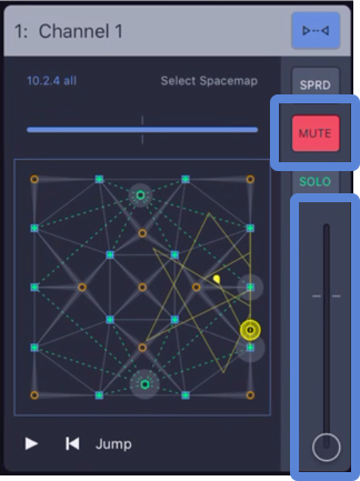
Spacemap Go – Mute and Input Fader Down
Connect or power on the loudspeakers.
Start sending audio from the playback device(s) and confirm audio input levels.
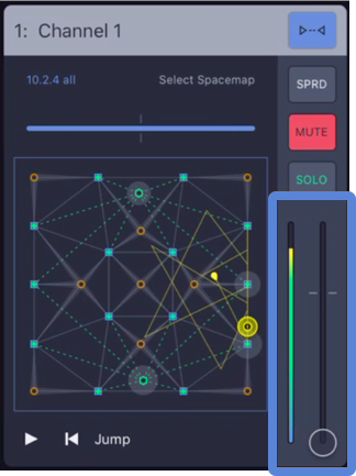
Spacemap Go – Input Meter and Input Fader
Similar to an input of a console, unmute each input and slowly raise the input fader. If the fader of the channel cannot be comfortably set to the nominal (0 dB) level, increase or decrease the Mix Level accordingly. Listen for the expected output.
Tip
One way to use the Mix and System Level is to treat the Mix Level as a “master fader” of the system and the System Level as a system-wide offset. Once the inputs are confirmed and a relative listening level is established, set the System Level to match the Mix Level and return the Mix Level to nominal (0 dB) for better fader resolution during operation. The Mix Level is stored with a Mix Snapshot. The System Level is saved with a System Snapshot.
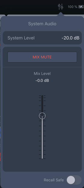
Spacemap Go – System Levels
Simple troubleshooting
If sound is not being reproduced by the loudspeakers, please check:
Input metering is indicated next to the channel in Mix View (to the right of the Spacemap of each channel).
The mix or system level is not too low or muted.
Mix View, for a channel receiving input, move the Spacemap Panner so that a Speaker Node with a connected loudspeaker indicates level.
Loudspeakers are connected to assigned processor outputs (for Demo 1-8 Mix Snapshot, Spacemap Go Ch 1-2 have Speaker Nodes associated with processor outputs 1-14).
Loudspeakers are powered on and patched.
At this point, if there is no sound coming from your loudspeakers, please contact us! Not only would we like to help you get things working, but we may also discover ways to make improvements to the app.
Interface
Operations
This section contains operational information for your reference as you proceed through these help pages. Included is an outline of a typical Spacemap System workflow, information about saving work, and an explanation of Spacemap System audio signal flow.
Typical steps to use the system
Saving in Spacemap Go
Spacemap processor control
Spacemap system audio signals
The Spacemap System controls and functions are listed below.
The System Status, Project Settings, Snapshots, and System Audio are available from any View (below).

Spacemap Go – System Status, Project Settings, Mix Snapshots, and System Audio

Spacemap Go – System Controls
This icon indicates the system connection status and is always visible.
If a connection problem occurs, it is indicated with the System Status icon. If the issue is not resolved within five seconds, the app opens the welcome screen. Select the system again if available. If the connection problem is resolved, the Spacemap System will appear on the welcome screen; tap to connect again. If the GALAXY processor(s) did not lose power, all the settings will remain untouched, even if any modifications were not saved.

Spacemap Go – System Connection Status
Tap the System Status icon to select another Spacemap System if there is more than one available. If no real or virtual GALAXY processors are discovered in Spacemap Mode, a connection message is displayed. On the right, links to provide feedback, Spacemap Go online Help, and the Meyer Sound website are provided.
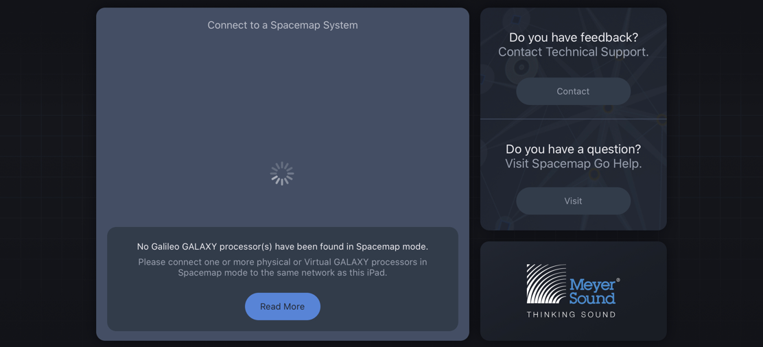
Spacemap Go – No Galileo GALAXY Processor Found in Spacemap Mode.
The System Connection window lists the Spacemap Systems available on the Network. If a System is not yet configured, the system is listed as Unconfigured. Tap a system name to configure that system.
Note
The Spacemap System Name is the Group Name entered for each processor in Compass software.
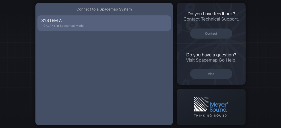
Spacemap Go – Available Spacemap Systems
System configuration wizard
The GALAXY processors of a system are listed. Tap each processor that has analog or AES3 inputs. Adjust the quantity of combined analog and AES3 inputs for each processor. Tap PROCEED if no analog or AES3 inputs are used.

Spacemap Go – Select Processors with Analog or AES3 Inputs, Select Total Number of Analog and AES3 Inputs for Each Processor
Adjust the number of AVB inputs used in the system. Tap SAVE TO SYSTEM. The input configuration is complete.
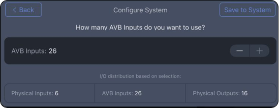
Spacemap Go – Adjust the Number of AVB Inputs
To modify the input configuration, tap SETTINGS VIEW. Select INPUT on the left, and tap RECONFIGURE INPUTS in the upper-right corner.
Displays Spacemap Go System Name and Project Name. Tap to open Project Settings pop-over menu (details are on the Project Settings page).
Displays the current Mix and Channel Snapshot names. Tap to switch to Setlist View.
Spacemap Systems have up to 32 channels. These channels are grouped in 4 layers. Each layer displays 8 channels. Tap a group to display the layer.

Spacemap Go – Layer Selection for Channels
The Overview option plots all 32 of the Spacemap Panner locations. Tap the Channel numbers on the left to show/hide individual Channels. One Spacemap can be selected and viewed when the SHOW SPACEMAP option is enabled.
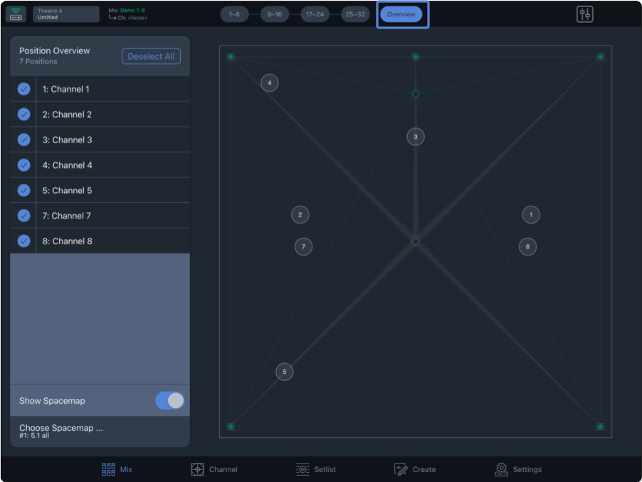
Spacemap Go – Mix View, Overview
Tap the  icon to open the System Audio popover. The color of the icon changes to red when the Mix Level is less than -30 dB and is filled red when the Mix Mute is engaged.
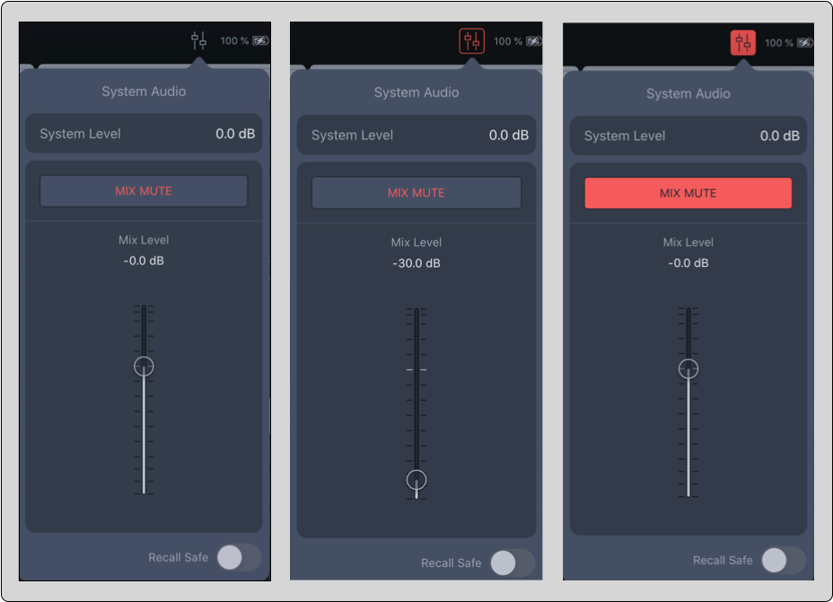
Spacemap Go – System Audio Popover
System Level
The System Level is stored with a System Snapshot. Use the System Level as an offset so the Mix Fader can be set near nominal when the system is operating at the desired output level.
Mix Level
The Mix Level and Mix Mute are stored with a Mix Snapshot. The Mix Level is intended for fine level adjustment during a performance. It is helpful to adjust the System Level so the Mix Level is near nominal (0 dB) for better fader resolution.
Project settings
The Project Settings button displays the Spacemap Go System name and the Project Name. Tap the button to open the menu.
Important
Do not store or recall Snapshots with Compass software or Compass GO while operating a Spacemap System. The Spacemap Go app manages the storage and recall of GALAXY processor settings.
Projects are the upper-most level of saving a Spacemap System, capturing all the parameters of a Spacemap System. When a Spacemap Go Project is saved, the System Snapshot, Mix Snapshot, User and Factory Defaults and the System Configuration are saved.
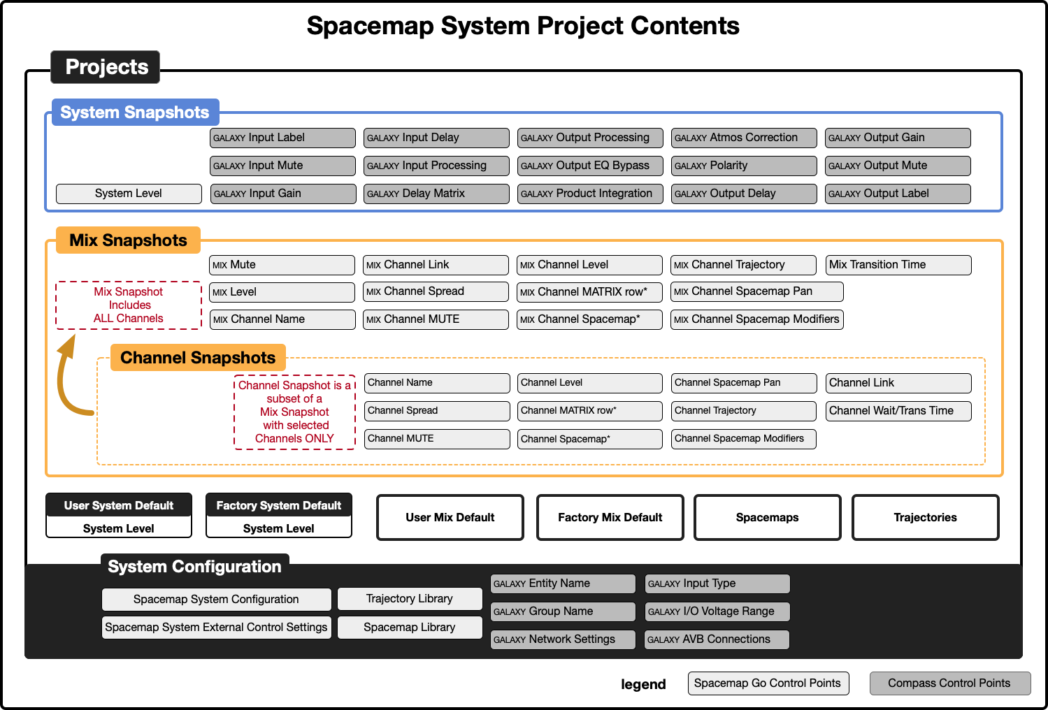
Spacemap Go – Project Contents and Organization
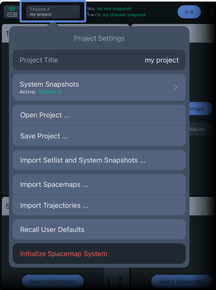
Spacemap Go – Project Settings
Project title
Tap PROJECT TITLE to edit or enter a new name.
System snaphsots
System Snapshots include the System Level, the GALAXY input and output processing, and the delay matrix control points. Tap to reveal controls to create new, delete, and update System Snapshots.
To store a new System Snapshot, tap and enter a name. Tap CAPTURE to finish.Tap the More icon (three-dots) to reveal controls to update the current System Snapshot with the current changes and display the System Snapshot details and External Recall ID number.
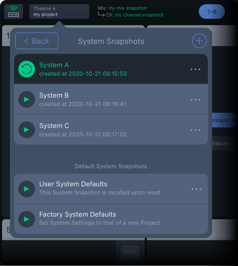
Spacemap Go – Project Settings, System Snapshot
Open and save a project
Tap OPEN PROJECT to open the desired file. Use the iPadOS browser to locate and open a Spacemap Go Project file.
Tap SAVE PROJECT to save or share a Project. Name the Project and select whether to save the file on the iPad, the GALAXY hardware, or both. One Spacemap Go Project can be saved to the hardware of the GALAXY processor(s).
This Project can be recalled when the system is powered on and LOAD PROJECT FROM GALAXY ON RESTART is selected (System Settings, System Configuration).
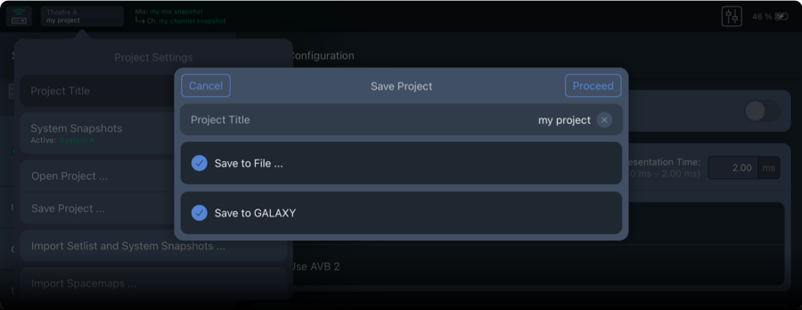
Spacemap Go – Save Project to iPad Files and GALAXY Hardware
The overlay offers different ways to share the file (via AirDrop, mail, messages, etc.). To save the Project file on the iPad, tap SAVE TO FILES and select a folder.
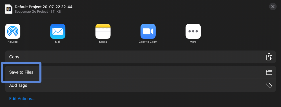
iPadOS – File Save Dialog
The app creates a Spacemap Go folder for convenience. To change the default file name, tap the Project name.
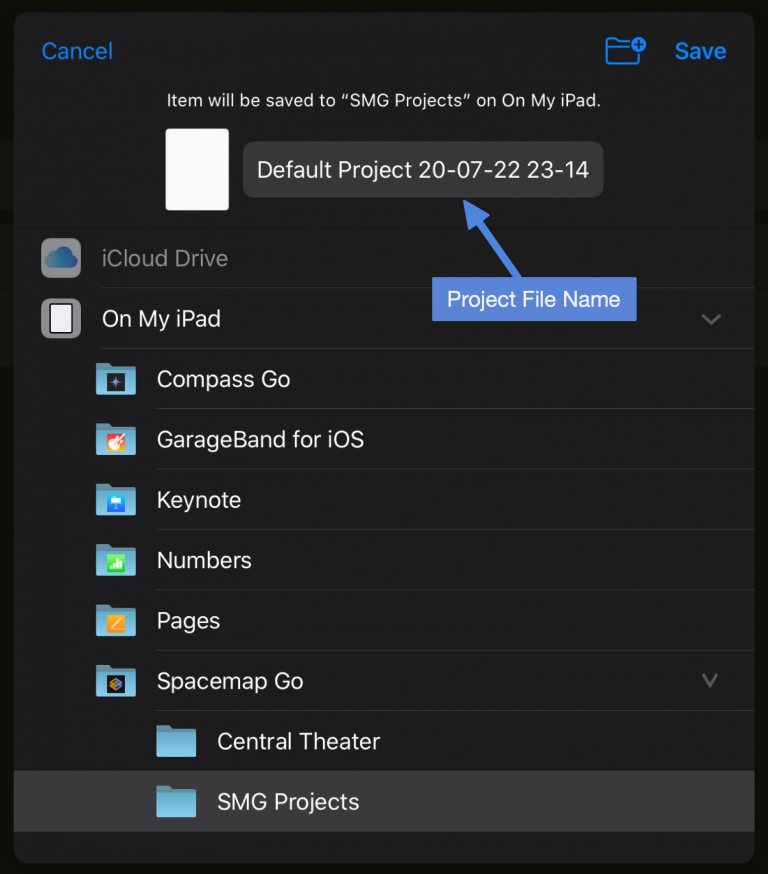
iPadOS – Save Project to On My iPad/Spacemap Go/SMG Projects
Import setlist and system snapshots
Tap to select a Spacemap Project from which to import the Setlist and System Snapshots. The imported Snapshots are added to the Snapshots already in the Project.
Import spacemaps and trajectories
Tap IMPORT SPACEMAP or IMPORT TRAJECTORY, then select the Spacemap or Trajectory file(s) to import. The imported Spacemaps or Trajectories are added to the Spacemap or Trajectory Library.
Recall user defaults
Tap RECALL USER DEFAULTS to recall the User System Defaults Snapshot.
Use the Setlist View controls to recall or update the Default Mix Snapshots. Tap the SHOW button in the Setlist View to reveal the Mix Default Snapshots. Tap the More menu (three-dots) to update the User Mix Defaults Snapshot.
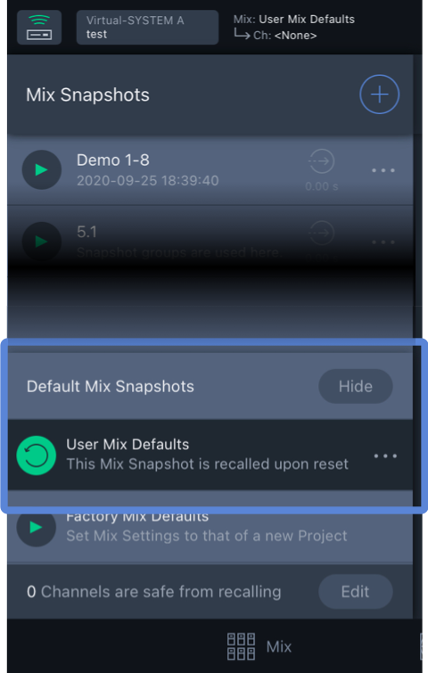
Initialize a Spacemap system
Tap INITIALIZE SPACEMAP SYSTEM to restore the original state of the app. The Mix and System Snapshots, Spacemaps and Trajectories will be deleted and replaced with the defaults.
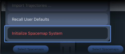
Spacemap Go – Project Settings, Initialize Spacemap System
Mix view
The Mix View presents common controls for 32 Spacemap Channels. For all controls of a channel, use Channel View.
Each Channel represents an input. There are three methods used to route an input signal to outputs:
Real-time gesture control of the Spacemap Panner
Automated control, using a Trajectory (predefined path) that the Spacemap Panner follows
Enter summing matrix cross-point levels (Channel View)
By default, Spacemaps are not selected and Matrix levels are set to -inf dB (off) — no path for audio exists between a system input and an output. This default state is similar to a mixing console input that is not assigned to any buses, matrix outputs, or master outputs.
Select a Spacemap
The Mix View displays eight input channels per layer, up to four layers, 32 channels, as well as an Overview of all channels. The eight active channels are highlighted, Channels 1-8 below.
Tap the SELECT SPACEMAPS button to choose a Spacemap for a channel.
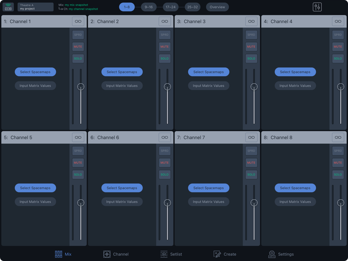
Spacemap Go – Mix View
Tap the ADD SPACEMAP button and select a Spacemap from the Choose Spacemap popover. Select APPLY TO ALL CHANNELS to assign the selected Spacemap(s) to all channels.
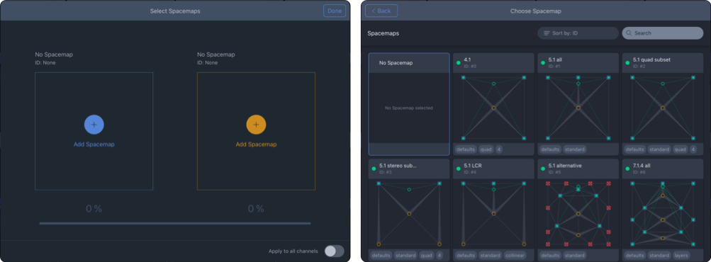
Spacemap Go – Select Spacemaps Window and Spacemap Library
Two Spacemaps can be selected for each channel. Tap the orange ADD SPACEMAP button to add a second Spacemap.
When two Spacemaps are added, use the percentage slider to change the percentage of the input signal sent to each Spacemap. The slider changes color depending on which Spacemap has the higher percentage, although both are routing audio unless the percentage is 0% for one of them. For example, using two Spacemaps, one Spacemap for lateral Speaker Nodes and another for overhead Speaker Nodes, fading between the two Spacemaps pans the input vertically. See details on the Spacemaps page.
Channel matrix values
The second option for routing an input to outputs is to enter cross-point Matrix levels. From the Mix View, tap the name of a channel or tap the Channel View button to open the Channel View. Use the arrows on either side of the channel name in the channel navigator to switch to the previous or next channel. Tap the channel name to open the channel selector pop-over and select another channel. Tap a matrix level to enter the output level for the channel. Swipe the Matrix row for additional outputs.
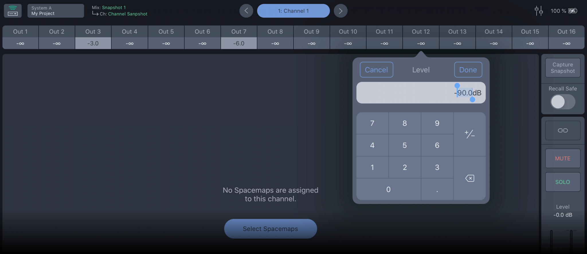
Spacemap Go – Channel Matrix Levels
Select a Trajectory
Trajectories are automated motion paths for the Spacemap Panner. When a Spacemap is assigned, the CHOOSE TRAJECTORY button is added below the Spacemap. Tap it to display the Trajectory Library. Tap a Trajectory to add it to the Spacemap.
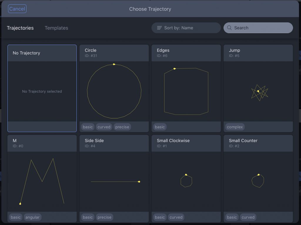
Spacemap Go – Trajectory Templates
From the Mix View, two controls are displayed below the Spacemap: one to play the Trajectory and another to reset the Trajectory. Tap the Trajectory Name next to these controls to open the Trajectory Library and select a different Trajectory or none.
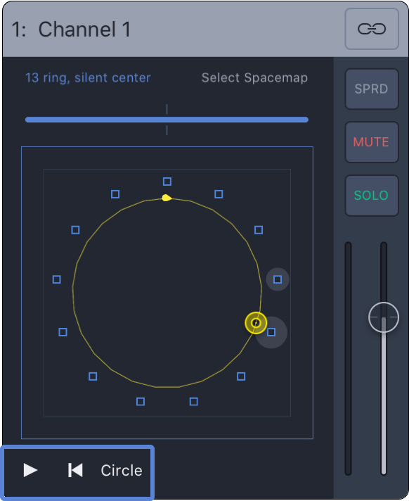
Mix View – Trajectory Controls
Remove a Spacemap or trajectory
To remove a Spacemap or trajectory from a channel, follow the same steps to add a Spacemap or trajectory and select NO SPACEMAP or NO TRAJECTORY from the library.
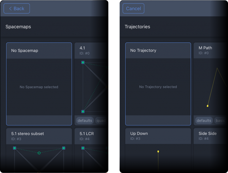
Mix or Channel View – Select No Spacemap or No Trajectory
Channel controls
Each channel has the following controls:
Input Level Meter: Visual indication of the input level.
Fader: Adjusts the audio level using a logarithmic slider. The nominal level (0 dB) is indicated by the grey line.
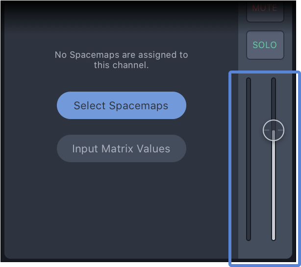
Mix View – Channel Signal Meter and Level Fader
 | Link: Tap this button to link the Fader Level, Solo, Mute, and Spread controls of odd/even channel pairs. Select a link mode for the Spacemap Panner – see options below. Select a Trajectory for the odd numbered channel of a linked pair. The Panner of the even numbered channel will follow the Trajectory of the odd channel depending on the link mode selected. |
SPRD: Regardless the Spacemap Panner position, the spread function routes an input signal to all of the Speaker Nodes in a Spacemap. Tap the SPRD button to open the percentage slider. At 0%, no additional signal is sent to Speaker Nodes. As Spread is increased, the surrounding nodes without signal start receiving the input signal. When Spread is set to 100%, all the Speaker Nodes receive the input signal at 0 dB, no attenuation. | |
MUTE: When MUTE is selected, audio is no longer routed to outputs from the channel. | |
SOLO: When SOLO is selected, only audio from the selected Channel is routed to outputs, commonly referred to as Solo In Place. |
MONO: Both linked channels have the same behavior.
NEAR X: The even channel follows the odd channel, but is offset horizontally to the right.
NEAR Y: The even channel follows the odd one, but is offset vertically from the top.
FAR X: The even channel follows the odd channel, but is offset horizontally further to the right.
FAR Y: The even channel follows the odd one, but is offset vertically further from the top.
MIRROR X: When the X value is positive for the first linked channel, the X value is negative for the second, and vice versa.
MIRROR Y: When the Y values are positive for the first linked channel, the Y values are negative for the second, and vice versa.
MIRROR XY: Both X and Y values are mirrored as described above.
Tip
When linked, the even channel indicates the linked status.
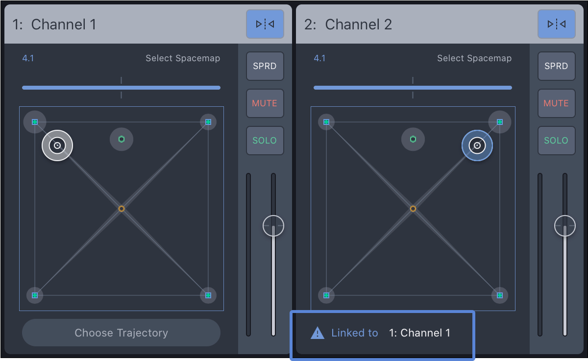
Mix View – Linked Channels
Channel name
Tap-hold the channel label to change the name. A popover window opens; edit the name, and tap DONE.

Mix View – Rename Channel Pop-Over
Channel view
The Channel View presents all of the controls for a single Spacemap Go channel to the user.
Fundamentally, Spacemap Go controls the Summing Matrix cross-point levels of Galileo GALAXY processors. Each Spacemap Go Channel represents a GALAXY processor input. Each input can be routed to any output at any level between -inf and 0 dB. The system outputs are represented as Speaker Nodes in the app.
For each channel, the Summing Matrix cross-point levels can be changed using one of three methods:
Real-time gesture control of the Spacemap Panner.
Automated control, using a Trajectory (predefined path) that the Spacemap Panner follows.
Enter summing matrix cross-point levels.
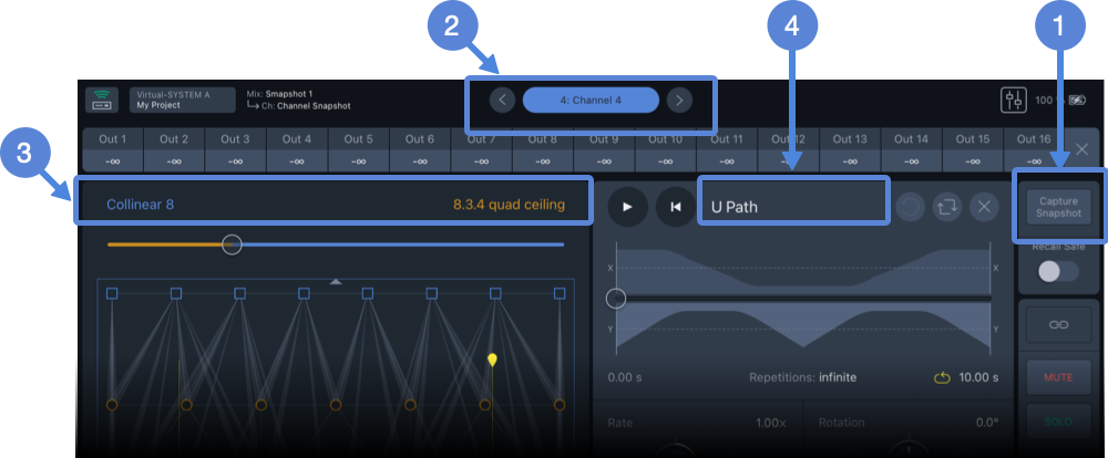
Channel View – Capture Channel Snapshot(1), Channel Navigation(2), Spacemap A & B (3), and Trajectory (4)
The settings of individual channels or groups of channels are stored and recalled using Channel Snapshots (Mix View). Individual Channel Snapshots can be created in the Channel View by tapping the Capture Snapshot button, above.
Use the navigation buttons to display the next or previous channel, above. Tap the channel name to open the channel selection pop-over. Tap-hold the channel name to edit.
Each channel can have one or two Spacemaps and one Trajectory,
above.
Tap the name of a Spacemap or Trajectory to open the library, make another selection or select none.
Summing matrix levels
For each channel, tap an output to manually enter a summing matrix cross-point level, routing the input signal of the channel to the selected processor output at the level entered. Swipe left/right to display additional outputs. Levels entered are overwritten if a Spacemap is added to a channel and the Panner is moved.
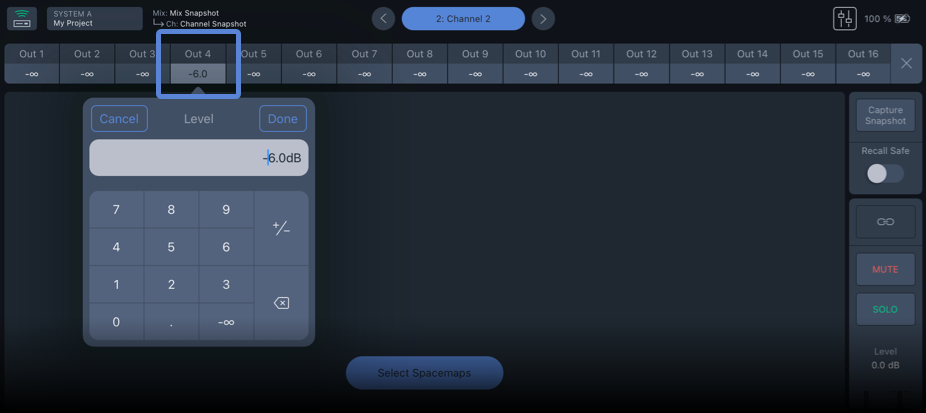
Tap Output to Enter Summing Matrix Cross-point Level
Add Spacemaps
Channels do not have Spacemaps selected initially. Each channel can use two Spacemaps. To select Spacemaps for a channel, tap in Mix View or Channel View. Then, tap either of the Add Spacemap buttons (below, left) to open the Spacemap library, which includes factory examples and user created Spacemaps (below, right). Swipe up/down to scroll the Spacemap library.
Use the Create View to add user-created Spacemaps to the Snapshot Library.
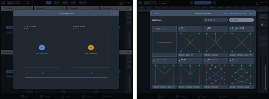
Select Spacemaps Pop-Over – Tap Either ADD SPACEMAP Button (left), Spacemap Library, Select a Spacemap (right)
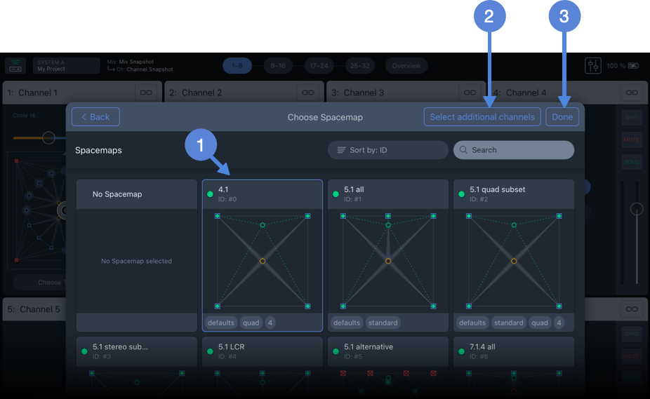
Choose Spacemap Pop-Over – Tap a Spacemap, SELECT ADDITIONAL CHANNELS or DONE to Add the Spacemap to the Channe
Tap a Spacemap to select it, above, then tap SELECT ADDITIONAL CHANNELS
to add the Spacemap to multiple channels or tap DONE
to add the Spacemap to the channel.
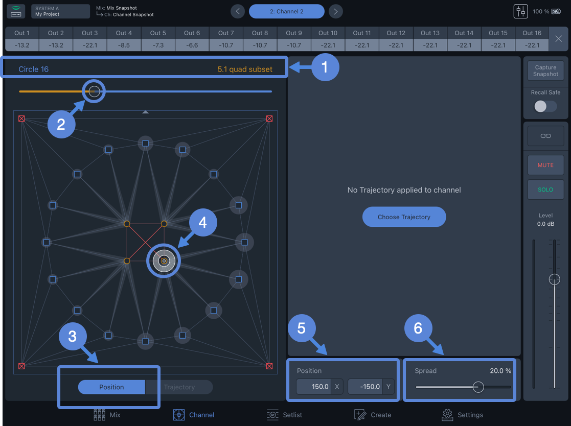
Channel View, Two Spacemaps Assigned, No Trajectory
SPACEMAP NAME: Tap either to make a different selection, including none.
PERCENTAGE: When two Spacemaps are added, this slider adjusts the percentage of input signal routed to each Spacemap. The slider changes color and the Spacemap displayed changes depending on which Spacemap has the higher percentage, although both are receiving signal unless the percentage is zero for either one. There are advantages to using two Spacemaps; see details on the Spacemaps page.
POSITION MODE: Enables gesture control of the Spacemap Panner
.
XY POSITION: Displays the X and Y coordinates of the Spacemap Panner. Tap values to enter coordinates
SPREAD: Controls how much of the input signal to routed to all of the speaker nodes in the Spacemap, regardless of the Spacemap Panner location. When set to 0%, no signal is “spread.” As the Spread percentage is increased, the level of the input signal routed to each Speaker Node is increased. When 100% is selected, the input signal is routed to all Speaker Nodes at 0 dB. This slider is logarithmic.
Add a Trajectory
Use the Create View to add user-created Trajectories to the Trajectory Library.
A Trajectory is a defined movement path for the Spacemap Panner. When a trajectory is selected, a yellow line representing the movement path is overlaid on the Spacemap, and the Trajectory controls are displayed on the right side of the Channel View.
Channels do not have Trajectories selected initially. Each channel can be assigned one Trajectory. To select a Trajectory for a channel, tap in either Mix or Channel View to open the Trajectory library, which includes factory examples and user-created Trajectories. Swipe up/down to scroll the Trajectory Library.
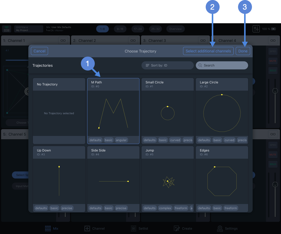
Select Trajectory Pop-Over – Tap a Trajectory, SELECT ADDITIONAL CHANNELS, or DONE to Add the Trajectory to the Channel.
Tap a Trajectory to select it, then tap SELECT ADDITIONAL CHANNELS to add the Trajectory to multiple channels, or tap DONE to add the Trajectory to the channel.
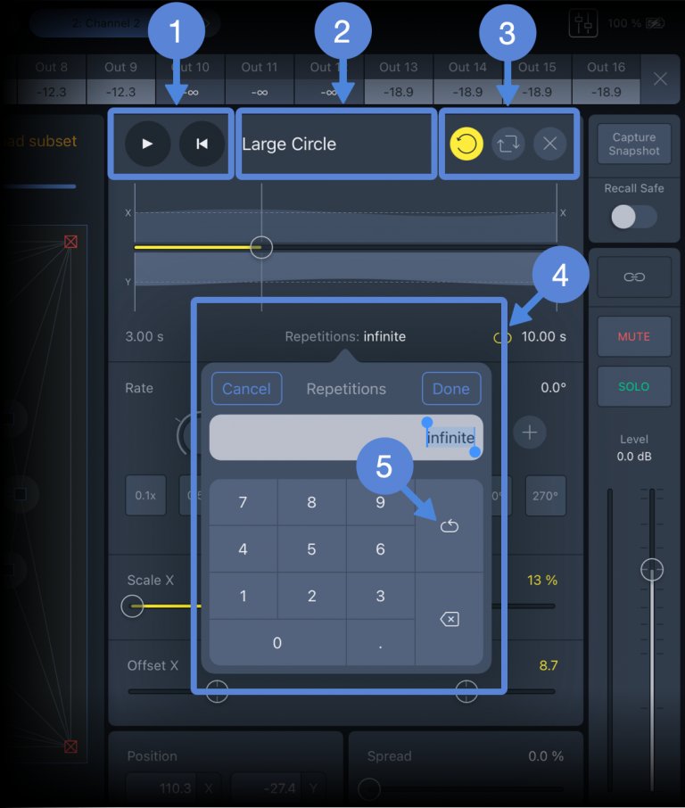
Channel View – Trajectory Controls
PLAY: Starts the Spacemap Panner following the Trajectory.Restart: Stops the Trajectory, if playing, and resets the play head to the beginning of the Trajectory timeline.
TRAJECTORY: Tap to select another Trajectory or none.
RESET: Opens pop-over, select: Reset All, Rate, Scale, or Offset. CHOOSE ANOTHER: Tap to select another Trajectory or none.REMOVE: Removes the Trajectory from the channel.
REPETITIONS opens pop-over, enter number of times to repeat or infinity
.
Tap the TRAJECTORY button to enable gestures to modify the Trajectory path overlaid on the Spacemap.
Use one-finger gestures to move the Trajectory, two-finger pinch/expand to scale, and two-finger twist to rotate.

Trajectory Movement
To switch between Rate and Tap Tempo controls, swipe left/right on the pane.
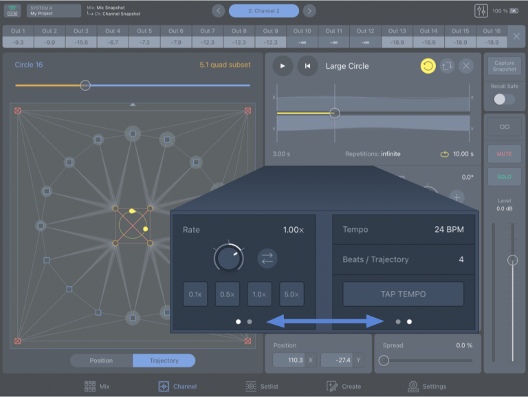
Channel View – Swipe Left/Right to Switch Between Rate and Tap Tempo Controls
RATE: Changes the speed the Trajectory is played. Tap-drag the encoder up/down to change the Rate.
REVERSE DIRECTION: Immediately reverses the direction the Panner travels along the Trajectory.
TEMPO & BPT: Change the Trajectory rate based on BPM or Beats/Trajectory. Tap to edit values.
TAP TEMPO: Tap repeatedly to set Tempo BPM manually – continue tapping until the Tempo BPM updates.
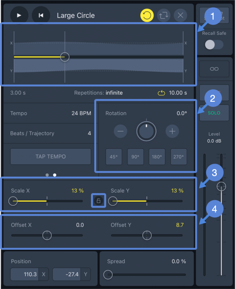
Channel View, Trajectory – Timeline and Rotation, Scale, and Offset Controls
TIMELINE: All changes are reflected on the Trajectory Timeline. The graphic consists of three horizontal axes; the middle represents the time of the trajectory. The other two depict the X and Y coordinates of the Panner.
ROTATION: To rotate the Trajectory, use the encoder, the plus/minus buttons, or tap a preset value.
SCALE: To change the Trajectory size, use the Scale X and Scale Y controls. Tap the Lock icon to link the Scale X and Y values absolutely.
NOTE: If the Spacemap area is exceeded by the Trajectory, it will change shape, respecting the boundary.
Channel controls
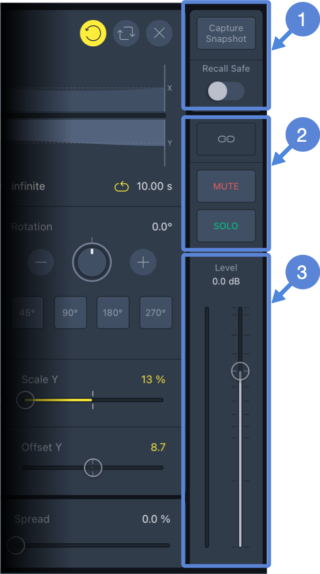
Channel View, Duplicate Controls Available in Mix View
CAPTURE SNAPSHOT: Creates a new Channel Snapshot, which includes: Channel Name, Link, Spread, Mute, Level, Matrix levels, Spacemap, Spacemap Pan, Trajectory and Spacemap modifiers.
RECALL SAFE: Prevents overwriting of the channel settings when either type of Snapshot is recalled. The Recall Safe state is not stored when Channel Snapshots, Mix Snapshots, or Projects are created or saved.
LINK, MUTE, SOLO: Are duplicate controls, also available in Mix View.
LEVEL and INPUT METER: Are duplicate controls, also available in Mix View.
Setlist view
The Setlist View facilitates storing and recalling Mix and Channel Snapshots and is usually used during a performance to recall individual Channel settings or groups of Channel settings.
Mix and channel Snapshots
A Mix Snapshot stores the parameters for all Channels plus the Mix Level and Mute.
A Channel Snapshot stores the parameters of an individual Channel.

Saving Hierarchy – Channel and Mix Snapshots
Overview
The Setlist View displays the Mix and Channel Snapshots in two panels. If the Mix Snapshot panel is hidden, tap button below to reveal.
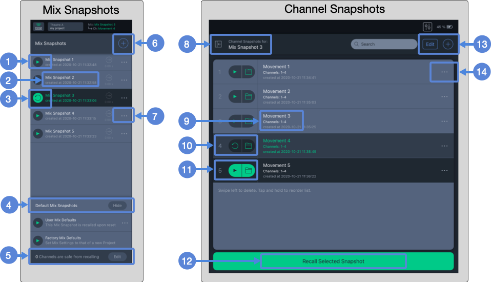
Setlist View – Mix and Channel Snapshot Panels
Recall this Mix Snapshot with confirmation
Mix Snapshot name and comment
Most recent Mix Snapshot Recalled. Tap
 to recall the Mix Snapshot again.
Default Mix Snapshots show/hide
Number of Channels with Recall Safe Enabled
Capture new Mix Snapshot
Opens popover to update or display Mix Snapshot details, view external recall ID#
Collapse/Expand Channel Snapshot panel
Channel Snapshot name, included Channels, and comment
Most recently recalled Channel Snapshot indicated by grey background. Tap again to recall.
Selected Channel Snapshot. Tap PLAY button or Recall Selected Snapshot button
to recall.
Recall selected Channel Snapshot
Tap EDIT to group/ungroup, move, or delete Channel Snapshot;
 to create new Channel Snapshot.
Update Channel Snapshot, update group, ungroup, edit details, or view external recall ID#
Mix Snapshots
To capture a new Mix Snapshot, tap the plus button , to open the popover. Enter a name for the snapshot and tap CAPTURE. The new snapshot will be added to the Mix Snapshots list.
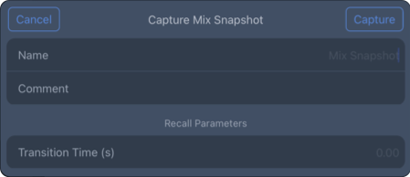
Setlist View – Capture Mix Snapshot Popover
Update a mix Snapshot
If changes are made to one or many channels, and the settings stored in a Mix Snapshot need to be updated, tap the three-dot icon next to the Snapshot Name, then UPDATE MIX SNAPSHOT. Any Mix Snapshot can be updated with the current settings of all the channels.
The Mix Snapshot column also lists the Default Mix Snapshots , which are hidden by default. Tap the SHOW/HIDE button to toggle the User and Factory Defaults display. There are two types of Mix Defaults:
User Mix Default: An additional, user-defined Mix Snapshot, used as a starting point at the beginning of a project or the start of a day. Tap the three-dot icon and select UPDATE MIX SNAPSHOT to update the stored parameters of all channels. This snapshot is recalled when the app connects to a Spacemap System.
Factory Mix Default: Mix Snapshot that returns all channels parameters to nominal, no Spacemaps assigned, and all matrix levels set to -∞ dB.

Setlist View – Default Mix Snapshots
The total number of channels that are set to Recall Safe is displayed . Tap EDIT to select channels to recall safe.
Recall mix Snapshot
Tap the Play Button to overwrite all the channels with the parameters stored in the Mix Snapshot. Tap RECALL to accept, CANCEL to decline. When a Mix Snapshot is recalled, the Play Button changes to a circle with an arrow at the end
; tap to recall the Mix Snapshot again.
Mix Snapshot options
Tap the three-dot icon to open the More pop-over to view these options:
Tap UPDATE MIX SNAPSHOT to overwrite the settings currently stored in the snapshot.
Tap UPDATE MIX SNAPSHOT to overwrite the settings currently stored in the snapshot.
Tap MIX SNAPSHOT DETAILS to edit the name, add a comment, or exclude channels when the snapshot is recalled. The external recall ID number is listed (for external control).
To exclude a channel, tap NONE (below) and select channels from the list to exclude them when the Mix Snapshot is recalled.
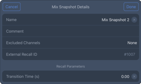
Setlist View – Mix Snapshot Details
Tap INCLUDED CHANNEL SNAPSHOTS to preview the Channel Snapshots without recalling the Mix Snapshot.
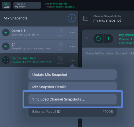
Setlist View – List Channel Snapshots in Mix Snapshot
Channel Snapshots
Setlist View: To store a Channel Snapshot, tap the ADD button . The Capture Channel Snapshot popover opens. Add a name and comment. Then tap CHANNEL to select the channels to include. Enter Wait and Transition Times if an immediate change is not desired. Tap CAPTURE to save a Channel Snapshot.
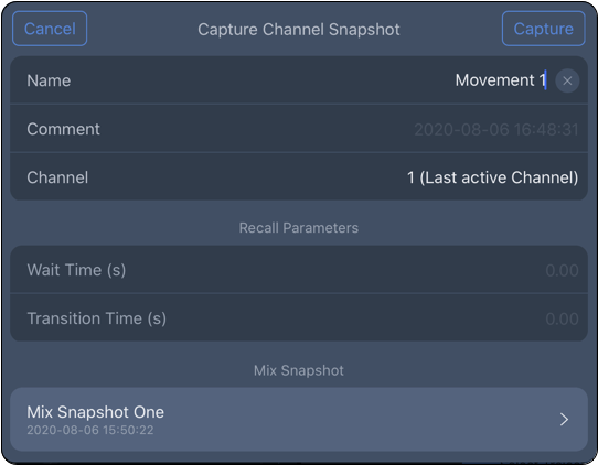
Channel View – Add Channel Snapshot
Channel View: Channel Snapshots are also saved/captured in Channel View. Tap the CAPTURE SNAPSHOT button (below). The Capture Channel Snapshot popover opens. Make the same entries and selections as above and select the Mix Snapshot with which to associate the Channel Snapshot.
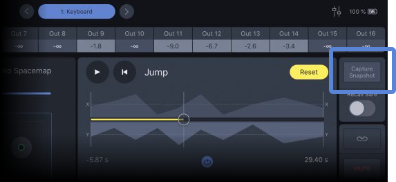
Channel View – Capture Snapshot Button
Group, move, and delete Snapshots
Tap the EDIT button and select Channel Snapshots to group/ungroup, move, or delete. Tap the desired action at the bottom of the pop-over. When GROUP is selected, a popover opens to name the Channel Snapshot Group. Groups are identified by a folder icon (FX 1 below) instead of displaying the channel number (Movement 1-3 below).
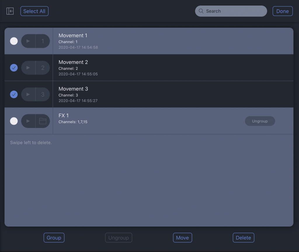
Setlist View – Group/Ungroup, Move, and Delete Channel Snapshots
To move/copy a Channel Snapshot to another Mix Snapshot, tap EDIT , select the channels to be moved, and tap MOVE. The popover that opens lists the possible destination Mix Snapshots.
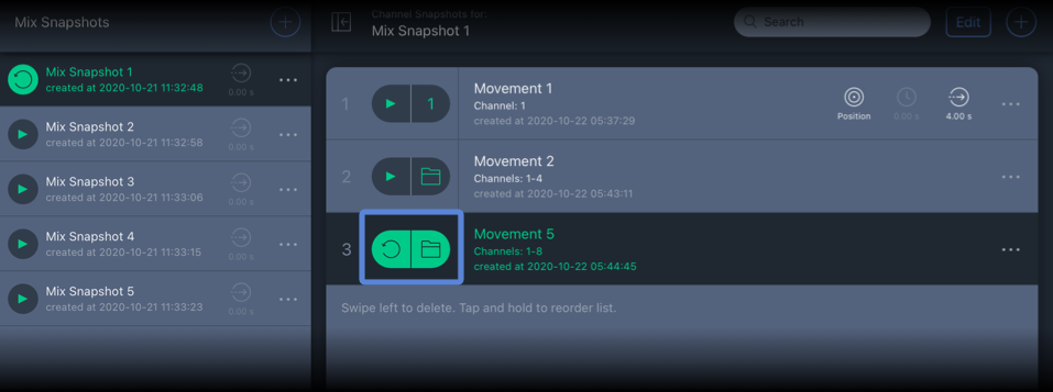
Setlist View – Channel Snapshot Group Indicated by Folder Icon
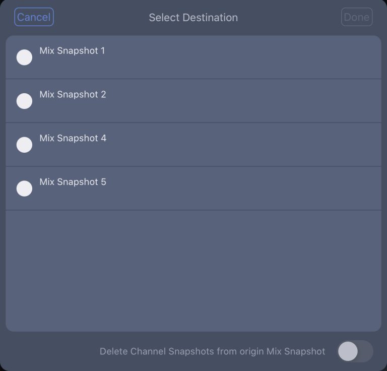
Mix Snapshot Selection
Delete mix or channel Snapshots
To delete a Mix or Channel Snapshot, swipe left on the Snapshot.
Important
This action cannot be undone. Channel Snapshots included in the Mix Snapshot are also deleted.
To delete many Channel Snapshots at the same time, tap EDIT , select the Channel Snapshots, and tap DELETE.
Create view
The Create View displays the Spacemap and Trajectory libraries. Tap the SPACEMAPS and TRAJECTORIES buttons at the top of the view to switch between the libraries.
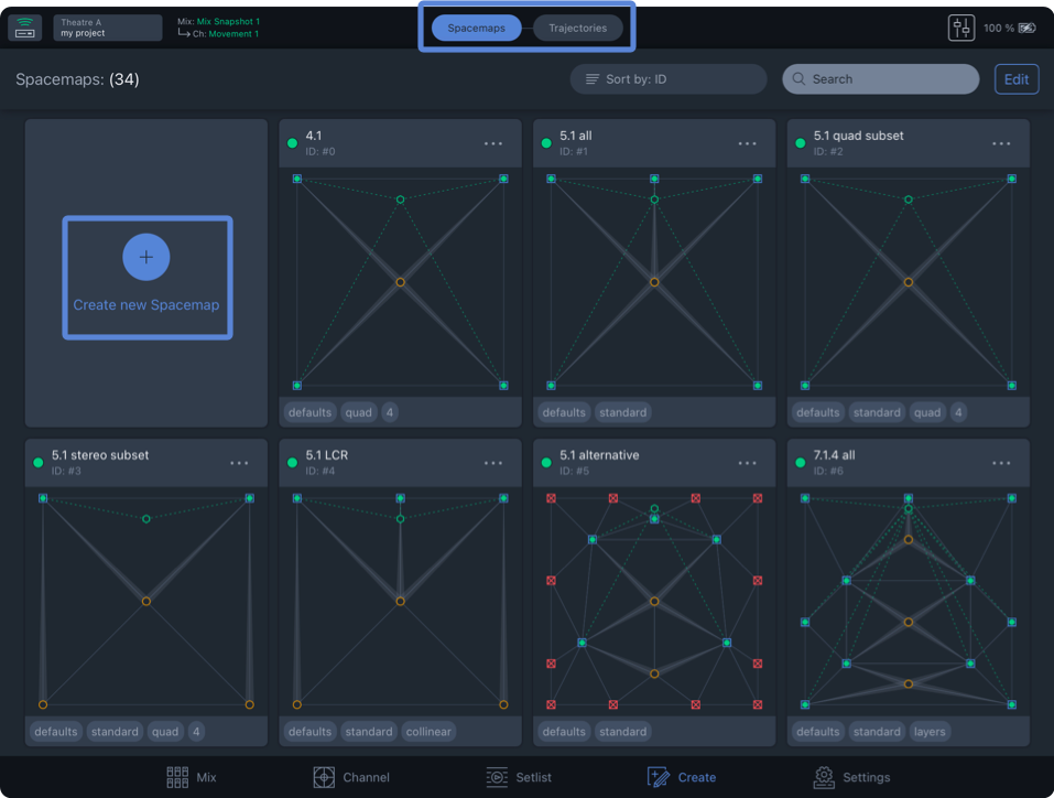
Create View – Spacemap Library
Create a new Spacemap
To create a Spacemap, select SPACEMAP at the top of the view and tap CREATE NEW SPACEMAP (above) to open the Spacemap editor.
Tap the ADD button on the right (below). Select one of the four node types on the left, then tap inside the Spacemap to add nodes. Use two-finger pinch and open gestures to zoom the Spacemap.
Tap More (three-dot icon) next to the Spacemap name to edit the name, save a Spacemap file, and add tags.
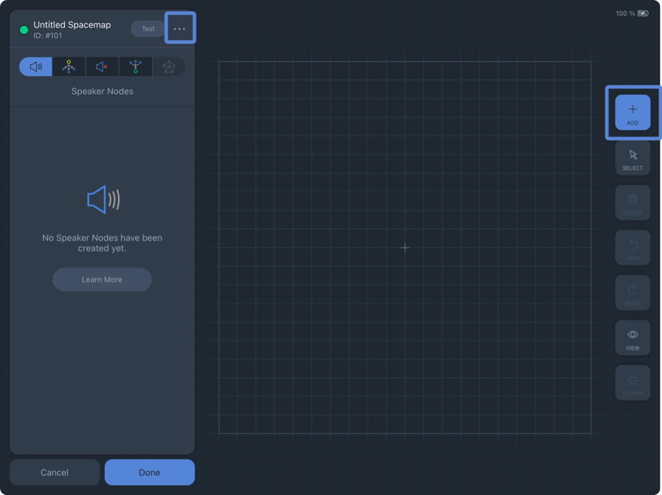
Create View – Add Spacemap
Nodes types
For more information about nodes and their uses in a Spacemap, please see the Spacemaps page.
 | Speaker Nodes Speaker Nodes represent the physical outputs of a Spacemap System as blue squares. Positions of Speaker Nodes in a Spacemap can represent the loudspeaker layout logically, randomly, or abstractly. Abstract layouts are usually used to facilitate specific panning scenarios that would be difficult or impossible to create with a logical speaker node layout. |
 | Virtual Nodes Virtual Nodes simulate a physical output for panning purposes and can be used in conjunction with Silent Nodes. Virtual Nodes are linked to Speaker Nodes and/or Silent Nodes. The links are indicated graphically by a translucent line, wider at the Virtual Node, narrower at the linked Speaker Node. When the Spacemap Panner is moved to a Virtual Node, the input signal is equally distributed to the linked Speaker Nodes by default. Each linked Speaker Node has a Link Weight that is adjustable (0–100%). |
 | Silent Nodes Silent Nodes are included in Trisets, just like Speaker Nodes, but they are not associated with an output. When the Spacemap Panner is moved closer to a Silent Node, all output levels of the channel are reduced. When the Spacemap Panner is on a Silent Node, all output levels of the channel are -∞ (-infinity) dB. Moving the Panner closer or further away from a Silent Node is an easy way to fade-in or fade-out a channel using the Spacemap Panner instead of the channel level control. In a Spacemap, when the Spacemap Panner is moved to a location that does not include a Triset, all of the output levels of the channel drop to -∞ dB. As the Panner is moved on and off of Trisets it will sound like the mute for the channel is being toggled. If this is not the desired effect, Silent Nodes can be added at the extents of a Spacemap with Trisets that include them. When Trisets fill the entirety of a Spacemap and the Spacemap Panner approaches the edge of the Spacemap, the output levels will not suddenly drop to -∞ dB. Instead, the output levels are gradually reduced as the Panner is moved closer to a Silent Node. |
 | Derived Nodes Derived Nodes link to one or more Speaker Nodes and receive the sum of the signals from the linked Speaker nodes. They are represented as hexagons in a Spacemap. Dashed lines indicate the Speaker Nodes to which they are linked. Derived Nodes are used as a method to send input signal to additional outputs, relative to the linked Speaker Nodes. They are commonly used for subwoofer sends, fill mixes, sends to balconies, and other cases where a secondary mix-down of a multichannel mix is required. |
 | Trisets At least one Triset is required in each Spacemap. Trisets are triangular panning surfaces created between three nodes that define the panning area between them. In conjunction with the relative location of the Spacemap Panner, Trisets are used by the app to determine the output levels for each node. The size of the Triset is not critical because the power-preserving panning law is proportional rather than absolute. The output levels are calculated based on the relative distance between the Spacemap Panner and each of the nodes that make up a Triset, rather than the actual physical distance within the grid of the Spacemap. If an area of a Spacemap does not have a Triset and the Spacemap Panner is moved there, the output levels will drop to -∞ dB (the input signal will not be sent to any output). Trisets can be generated automatically or added manually when creating or editing Spacemaps in Create View.  |
Toolbar
Tap the tools to the right of the canvas to add, select, or delete nodes in the Spacemap.
 Toolbar | ADD: Tap in the Spacemap to add the selected node type. |
SELECT: Tap a Node or Triset to edit or move it. | |
DELETE: Tap to delete the selected Nodes or Trisets. | |
UNDO: Tap to undo the last change. | |
REDO: Tap to redo the last undo. | |
VIEW: Opens Spacemap view option popover for Spacemap (see below). | |
CENTER: Zoom to extents. |
View options
The View popover has several options that facilitate Spacemap creation:
SHOW SPACEMAP: A Spacemap can be selected as reference for node locations.
SHOW GRID: Toggles display of grid lines.
SNAP TO GRID: When enabled, nodes are only added at grid intersections.
BLOCK GRID SIZE: The grid size is adjusted in four increments.
SHOW CIRCULAR GUIDE: Overlays a circle with a number of snap points equally spaced. Use sliders to adjust size and number of points (Spacemap only).

Create View, View Options – New Trajectory (left), New Spacemap (middle), New Spacemap with Show Circular Guide On (right)
Test Spacemap
Tap the TEST button next to the Spacemap name in the upper-left corner to open the Spacemap Test View.
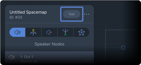
Create View – Spacemap Test Button
Move the Spacemap Panner, observe the output levels and confirm desired behavior.
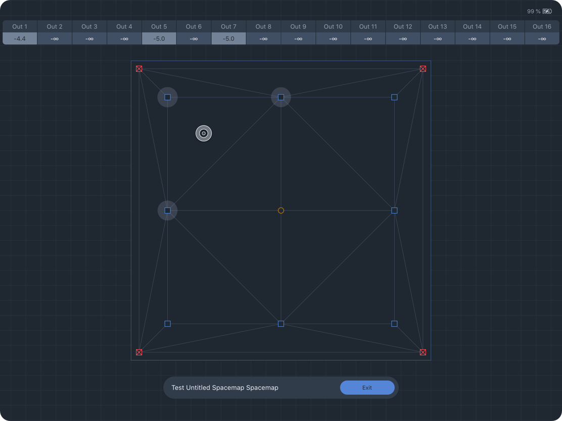
Create View – Spacemap Test Mode
Create a new Trajectory
To create a Trajectory, tap TRAJECTORY at the top of the Create View. Tap  CREATE NEW TRAJECTORY to open the Trajectory editing controls. Tap START RECORDING and draw inside the Spacemap to create a path. Tap FINISH RECORDING to end. Use two-finger pinch and open gestures to zoom the Spacemap.
A trajectory is a series of points that can be edited. Tap TIME and POINTS to edit values. Two times are listed for each point. The first is the wait time, the second is the time between consecutive points. The total time can be edited—modifying the individual wait and next-point times proportionally.
Tap the three-dot icon next to the name in the upper-left to edit the name, save as a Trajectory file, and add tags.
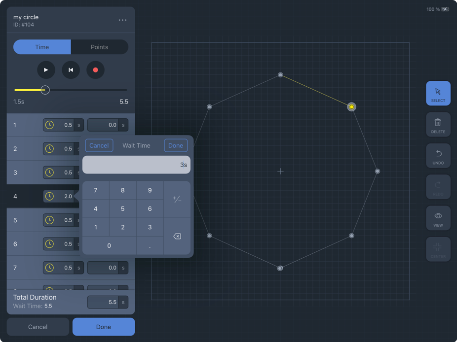
Create View, Trajectory Editor – Edit Wait Time for Point 4
Tap-hold and move a Trajectory Point to modify the trajectory shape. The POINTS option lists the X,Y coordinates (-1000 to 1000) for each point. Tap to edit values. Tap DONE to add the Trajectory to the library.
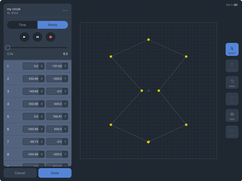
Create View – Edit Trajectory Points
Settings view
The Settings View includes System Settings and App Settings on the left side of the view.
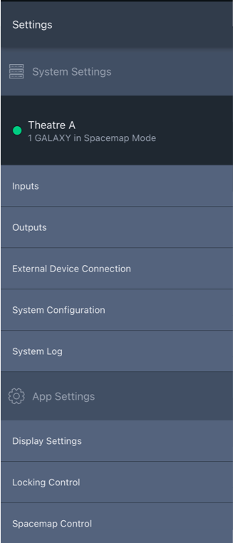
Settings View – System and App Settings
System settings
System Settings includes controls and functions not related to mixing or appearance. Tap the buttons on the left to reveal the associated details and settings.
Galaxy processor status
Tap the name of a Spacemap System to display details about each connected GALAXY processor.
Three colors differentiate the state of each processor (below).
GREEN: The processor is online and operating normally.
YELLOW: Indicates the module is connected but is not part of a Spacemap System.
RED: Indicates the processor is defined as part of a system but is not connected.
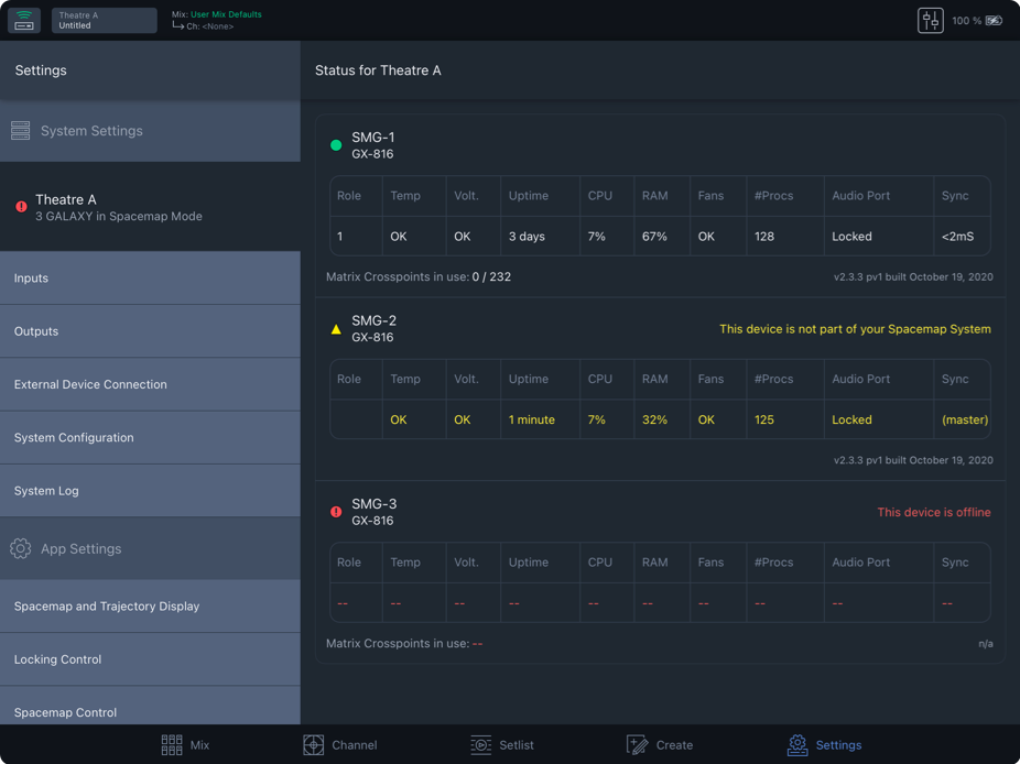
Settings View – System Status, Reported Processor States
Inputs
Outputs
External device connection
System configuration
System log
App settings
Display settings
Locking control
Spacemap control
Spacemaps
This sction includes definitions and examples of items that are used to create a Spacemap. See Create View for Spacemap creation and editing instructions.
What is a Spacemap?
Spacemap Go uses a graphic interface to control multichannel panning, the placement and movement of sound through space. Traditional pan controls for stereo systems are one-dimensional, panning sound along a line between two points: left and right. A Spacemap uses a two-dimensional interface to represent either a 2D or 3D space, determined by its layout. The Spacemap Panner of each channel is used to move or pan a sound in a Spacemap. Each input of a Spacemap Go System can have one or two Spacemaps assigned to it.
Spacemaps have two basic elements: Nodes and Trisets. Nodes ( below) commonly represent the positions of loudspeakers or groups of loudspeakers, and have several types. Trisets
link three nodes together, providing the means to distribute signal proportionally among them using an equal-power panning algorithm. The input of a channel is represented by the Spacemap Panner
. The closer the Panner is to a Speaker Node, the more the input signal is sent to the outputs associated with that node. When an area of a Spacemap does not have a Triset
and the Panner is moved to the area, the channel output levels drop to -∞ dB (minus infinity dB). A Trajectory
is the path along which the Spacemap Panner
can travel.
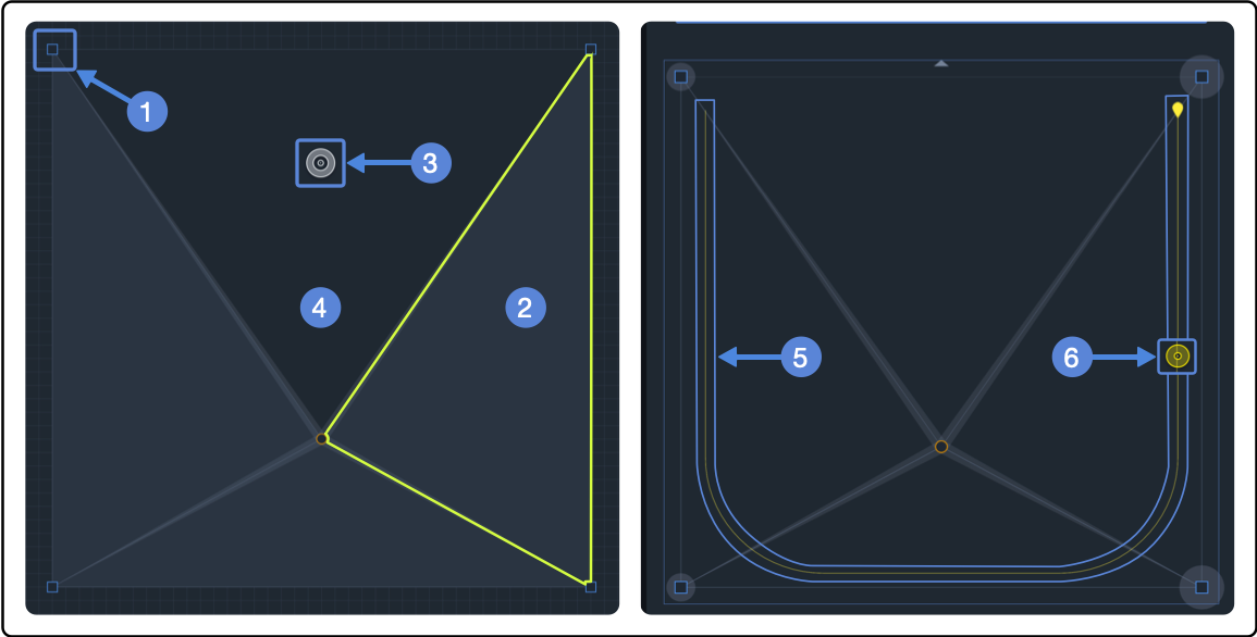
Spacemap – Nodes (1), No Triset (2), Spacemap Panner (3), Triset (4), Trajectory (5), Panner Following Trajectory (6)
Nodes
Nodes in a Spacemap are static locations that, based on the Spacemap Panner’s relative location, cause the input signal to be sent to outputs at different levels.
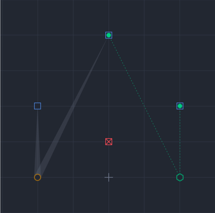
Spacemap Go – Node Types: Speaker, Virtual, Derived, and Silent
Speaker nodes 
Speaker nodes represent the GALAXY processor outputs of a Spacemap System and are represented in the app as blue squares. Positions of Speaker Nodes in a Spacemap can represent the loudspeaker layout logically, randomly, or abstractly. Abstract layouts are usually used to facilitate specific panning scenarios that would be difficult or impossible to create with a logical speaker node layout. Each Speaker Node is associated with only one output. However, multiple Speaker Nodes can be associated with the same output. These outputs can be connected to loudspeakers, effects processors, or any other audio device.
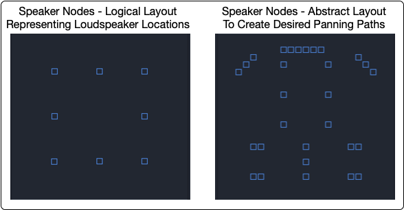
Spacemap Go – Speaker Node Arrangement Examples
Assign each Speaker Node to an output. Tap the More icon next to a Speaker Node and tap SET OUTPUT to open the pop-over and select an output. Multiple Speaker Nodes can be assigned to the same output.
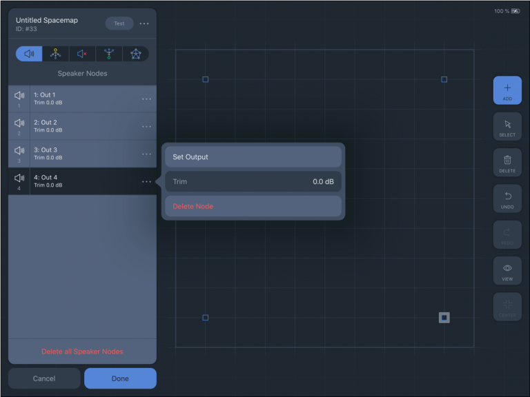
Spacemap Go – Create View: Speaker Node Parameters
Speaker nodes example 1: Circle
This video illustrates a sound panning around a circle of 12 Speaker Nodes. The arrangement of the Speaker Nodes in the Spacemap and loudspeaker layout are the same. The Speaker Nodes in the Spacemap are assigned to outputs sequentially. The loudspeakers are connected to those outputs sequentially. When the Spacemap Panner follows the circular trajectory, sound smoothly pans from one loudspeaker position to the next, panning the sound around the room.
Speaker nodes example 2: Circle shuffle
 ULTRA-X80 Datasheet (x/xx/xxxx)
Virtual nodes 
Virtual Nodes simulate a physical output for panning purposes and can be used in conjunction with Silent Nodes. Virtual Nodes are linked to Speaker Nodes and/or Silent Nodes. The links are indicated graphically by a translucent line, wider at the Virtual Node, narrower at the linked Speaker or Silent Node. When the Spacemap Panner is moved to a Virtual Node, the input signal is equally distributed to the linked Speaker Nodes by default. Each linked Speaker Node has a Link Weight that is adjustable (0-100%), see below.
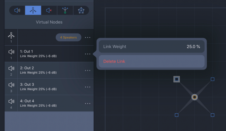
Spacemap Go – Create View, Four Speaker Nodes, One Virtual Node, Output 1 Link Weight
Virtual Nodes are commonly used to complete a Triset, while not being linked to an output. Below, the left Triset uses an un-linked Virtual Node. As the Spacemap Panner moves closer to the Virtual Node that is not linked, the level for Outputs 1 and 2 decreases to -∞ dB. The right Triset uses a linked Virtual Node. As the Spacemap Panner moves closer to this node, because it is linked to both Speaker Nodes, the level for Outputs 1 and 2 increases to a maximum of -3 dB.

Spacemap Go, Spacemap Test Mode – Upper Virtual Node Un-Assigned, Lower Virtual Node Assigned to Outputs
Virtual Nodes can be used in a Triset with one or two Silent Nodes. Adjust the Link Weights of the Virtual Node to alter the panning results.
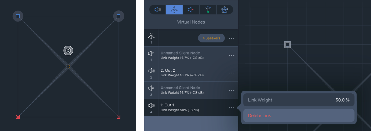
Virtual node example 1
Below, the Virtual Node in the center of the Spacemap is linked to the four Speaker Nodes in the four corners. As the Spacemap Panner is moved closer to the Virtual Node, the signal is equally distributed among linked speaker nodes. A trajectory traveling around the perimeter of this Spacemap pans from one speaker node to the next. A trajectory that moves toward the Virtual Node (center) causes the signal to spread out to all four Speaker Nodes gradually. This proportional distribution method creates a convincing phantom image throughout the panning area.
Virtual Node example 2: 3D Movement
If movement of a sound from lateral loudspeaker positions to overhead positions is desired, one method is to use an abstract layout of the Speaker Nodes with linked virtual nodes. Trisets are built including the Virtual Nodes. The Trajectory below pans between the Virtual Nodes, enabling vertical sound movement, simplifying operation.
play video
Silent nodes 
Silent Nodes are included in Trisets, just like a Speaker Node, but they are not associated with an output. As the Spacemap Panner is moved closer to a Silent Node, all output levels are reduced. When the Spacemap Panner is on a Silent Node, all output levels are reduced to -∞ dB. This is an easy way to create fade-in and fade-out effects based on the Panner location rather than using the level fader of the channel.
When the Spacemap Panner is moved to an area of a Spacemap that does not have a Triset, the outputs will suddenly drop to -∞ dB. To avoid this, add Silent nodes at the extents of a Spacemap and build Trisets that include them. The Panner will no longer be able to “fall off” of a Triset because the entire Spacemap is “covered” by Trisets.
Silent Node Example
Below, four Silent Nodes are added to the corners of the Spacemap. Trisets are added that include the Silent Nodes. By adding the Silent Nodes and Trisets, the Spacemap Panner can be moved to any point in the Spacemap without causing all of the channel output levels to drop to -∞ dB. As the Spacemap Panner approaches the Silent Node, the output levels are reduced, providing a smooth fade-out. When the Panner reaches the Silent Node, all of the output levels of the channel are reduced to -∞ dB.
Derived nodes 
Derived Nodes link to one or more Speaker Nodes and receive the sum of the signals from the linked Speaker nodes. They are represented as hexagons in a Spacemap. Dashed lines indicate the Speaker Nodes they are linked to.
Derived Nodes send the input signal to additional outputs, relative to the linked Speaker Nodes. They are commonly used for subwoofer sends, fill mixes, sends to balconies, and other cases where a secondary mix-down is needed.
When a Derived Node is added, it is assigned to the next available output, which can be changed, see below. Each link level of the associated Speaker nodes can be adjusted, see below.
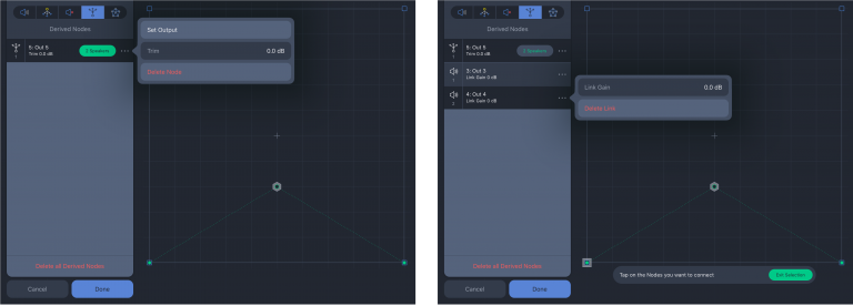
Spacemap Go – Create View: Derived Node Options and Speaker Node Link Level Adjustment
In the example below, the Derived Node output is connected to a subwoofer. The Derived Node is linked to the left and right Speaker Nodes, outputs 1 and 2. The subwoofer receives a constant signal as the Spacemap Panner is panned between the Speaker Nodes. When the Panner is centered between outputs 1 and 2, they each receive -3 dB level, while the Derived Node (output 5) receives 0 dB. When the Panner is moved to the right, the levels change for outputs 1 and 2, while the level of output 5 remains unchanged.

Test Spacemap – Spacemap Panner Moved from Center to Right, Derived Node Level Remains the Same
Trisets
Trisets are triangular, planar, panning surfaces that enable smooth panning without signal drops. Just as a conventional pan pot requires two points (the minimum required to define a line), a Triset requires a minimum of three points (the minimum required to define a plane). When building Trisets, three nodes (points) are used to define an area. The area between the selected nodes becomes the Triset (plane).
The size of the Triset is not critical because the power-preserving panning law proportionally scales: the relative distance between the Spacemap Panner and each of the Triset’s three nodes, rather than the actual physical distance within the grid, determines the output levels.
Usually, nodes are added to a Spacemap in such a way that when Trisets are added, the entire area of a Spacemap is “covered” by Trisets. If the Spacemap Panner is not on a Triset, all the output levels of the channel immediately drop to -∞ dB, which may not be desired.
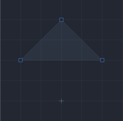
Spacemap Go – One Triset Including Three Speaker Nodes
Trajectories
When a Trajectory is added to a Spacemap and then played, the Spacemap Panner follows the Trajectory path, automating the Panner movement. A Trajectory can be recorded, edited, and reshaped, then assigned to an input channel, played, and can even be modified while it is playing.
One Trajectory can be assigned to each Channel. Each trajectory is an independent entity, with no absolute relationship to any Spacemap. The same Trajectory can be assigned to different Channels and played simultaneously using different modifications for each. All or some of the Channel Trajectories can be active at the same time, each being independently started and stopped. See Channel View page for control details.
From the Mix View, a Trajectory can be started, stopped, and reset (below, left) by tapping the transport icons at the bottom of each channel. All of the Trajectory controls are available in the Channel View, including real-time modifications: rate, tap tempo, rotation, scale, and position offset (below, right).
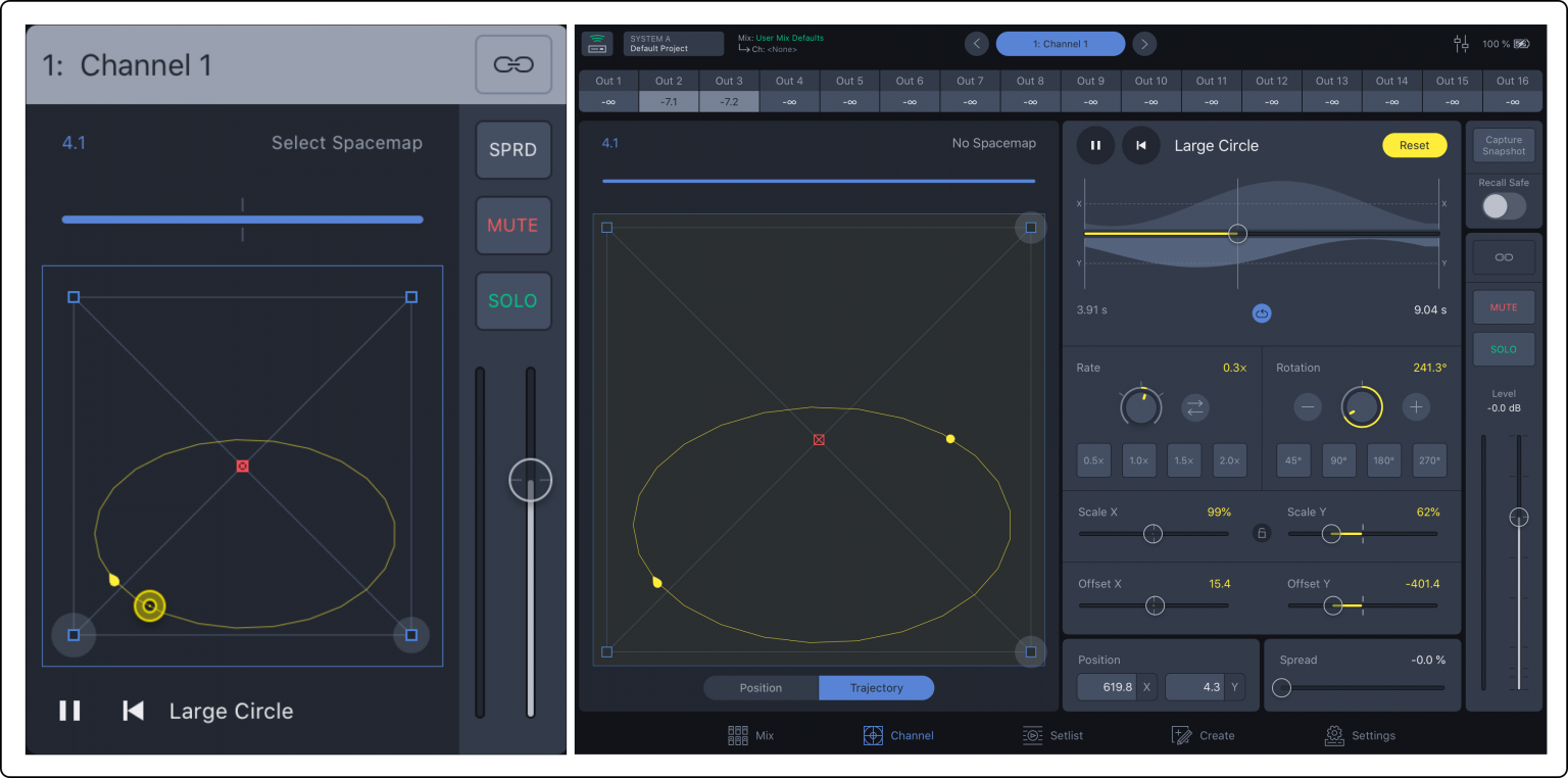
Spacemap Go – Mix View Channel with Spacemap and Trajectory, Channel View with Trajectory Editing Selected
Two Spacemaps per channel
Each Spacemap Channel can have two Spacemaps assigned. The level sent to each is adjusted with a slider, changing the percentage of the input signal sent to each Spacemap. The Spacemap with more than 50% selected is displayed on the Spacemap canvas. They both remain active unless 0% is selected for either Spacemap. This function adds another dimension of panning to Spacemap Systems. Below, the percentage is set with the horizontal orange/blue slider.
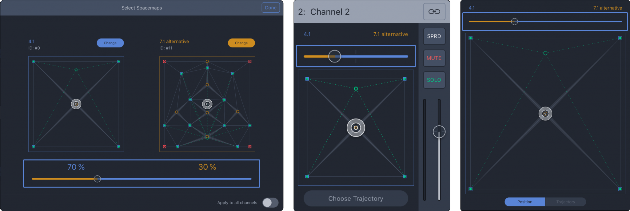
Spacemap Go – Select Spacemaps, Mix View of Channel, Channel View of Spacemap
3D Spacemap examples
Three-dimensional movement of a sound source can be accomplished using one of these methods:
3D Method 1
Create a Spacemap with nodes representing surround/lateral loudspeaker positions around the edge of a Spacemap and overhead loudspeaker locations near the center of the Spacemap. Move the Spacemap Panner around the edges for lateral panning and towards the middle to move the sound vertically.
Example: 10 surround and 4 overhead loudspeakers are represented in their logical locations in the Spacemap. The video below pans the input around the lateral positions at the edge of the Spacemap, then overhead by moving the Spacemap Panner towards the middle four nodes.
3D Method 2
Each channel in Spacemap Go can have two Spacemaps assigned. A percentage of the input signal can be sent to each Spacemap (0-100%), a cross-fade between the two. For example, Spacemap A could represent the lateral loudspeaker locations and Spacemap B could represent the overhead locations.
Example: Spacemap A has 10 lateral speaker nodes (outputs assigned from 1 to 10) and Spacemap B has 4 overhead speaker nodes (outputs assigned from 11 to 14). As the Spacemap cross-fade is adjusted, the output levels (top of the view) change, panning the sound vertically in the listening area.
Loudspeaker system design
by Bob McCarthy
There are an unlimited number of ways to design a loudspeaker system for immersive experiences; it depends on what you want the audience experience to be; it is an artistic decision. A minimum of two loudspeakers and two processor outputs are required for panning using Spacemap Go. Beyond that, a Spacemap Go loudspeaker system has no restrictions.
A typical loudspeaker system used to amplify or reproduce audio sources is designed for minimum overlap of loudspeaker coverage, where each audience location receives correlated signals from the minimum number of sources. Spacemap Go loudspeaker system designs are different: each audience location is covered by all of the loudspeakers. Each audience member can receive uncorrelated signals from all the loudspeakers, depending on the artistic desires.
The system design information below is a guide to selecting loudspeaker models, locations, and aiming for an immersive Spacemap System. The goal of this example immersive system is to provide continuous panning from one sound source to another, observable by the maximum number of audience members, allowing the audience to localize a source anywhere within half of a sphere. We will refer to this set of criteria as a “granular system.” Other design goals may use different system design methods, which are completely valid. Please contact Meyer Sound or solicit ideas from the Spacemap Go Forum (link above) if you have questions or comments.
Video references
SMG Origami Loudspeaker System Design v1: A tangible method to determine locations and spacing for loudspeakers.
System Design Roundtable #1, 2021-01-13: Fundamentals of design and methodology, with Spacemap examples.
System Design Roundtable #2, 2021-01-20: Design examples for various room shapes, with Spacemap examples.
System Design Roundtable #3, 2021-01-27: Design examples with balconies and fills, with Spacemap examples.
Loudspeaker homogeneity (sameness)
To preserve localization, rooms with low reverberation times and minimal echoes are desirable. Acoustically reverberant and reflective rooms will cause sounds to localize to additional points in the room or become less distinct. If that is not the desired aesthetic, change the acoustic properties of a room, which usually involves adding materials to either enhance or dampen reflections. Selection of loudspeaker models based on directivity and careful aiming of the loudspeakers can change the amount of sound that reaches acoustically reflective surfaces.
Room acoustics
Spacemap Go interactive application
Spacemap Go at its core is a graphic interface, that has a core function of controlling the summing matrix cross-point levels of GALAXY processors. The iPad interface uses a virtual representation of loudspeaker locations. The locations can mirror the real loudspeaker locations or can be arranged abstractly, in any way desired. If a Speaker Node is at the “rear” of a room, the sound will not move to rear of the room if no loudspeaker is there – no matter what the app displays. Physical reality requires that sound sources exist at milestone locations, allowing Spacemap Go to “pan” a given input between them.
Terminology used
Lateral System: Loudspeakers placed around the room perimeter, perceived as having a relatively low vertical orientation to the listener, less than 45° above them, e.g., side and rear surrounds.
Overhead System: Loudspeakers placed above the listeners, perceived as having a relatively high vertical orientation to the listener, more than 45° above them.
360° “Fully Granular”: Each loudspeaker is a unique Spacemap node, capable of being perceived as the exclusive image source of a given signal channel.
Coverage Pattern: The range of frequencies in which a loudspeaker model is directional. These are higher frequencies, almost always reproduced by a compression driver and a horn or a dome tweeter, usually above 2 kHz, depending on the model.
In Coverage or Covers: These phrases refer to SPL in a loudspeaker’s coverage pattern. An area is defined as “in coverage,” if the area has less than 6 dB of variation from the loudest point to the quietest point.
Design criteria
Loudspeaker coverge
Loudspeaker models
This design method utilizes wide (horizontal) coverage loudspeakers. The family of 110° wide loudspeakers is preferred (current products): LYON-W, LEOPARD, ULTRA‑X40, ULTRA‑X20/23, UP‑4slim, UP‑4XP, HMS‑12, Ashby‑5C/8C, MM‑4XP, MM‑4XPD. The family of 80° to 90° wide loudspeakers may require slightly higher density (current products): LYON‑M, UPQ‑D1/D3, UPJ‑1P, HMS‑5/10/15/15AC.
Design goals
Before designing a Spacemap Go system, it is important to understand what the artistic and aesthetic goals of the system are, and what content is intended to be reproduced. If a system will be used to continuously pan a sound horizontally around a space, a Lateral, 360° Granular design is needed (example on the left, below). To smoothly pan above the audience’s heads, an Overhead, 360° Granular design is needed (center, below). To pan a sound from one corner to overhead to the opposite corner, an 360° Fully Granular design is needed (right, below).
For the examples below, the design goals are:
Multi-channel main system
Fully granular lateral system
Fully granular overhead system
Low frequency system

System Design Goals – Lateral Panning (left), Overhead Panning (center), Lateral to Overhead to Lateral Panning (right)
Design steps
Define the Space: Loudspeaker Perimeter, Coverage Area, “Go Distance” and “Go Zone.”
Main System: horizontal spacing, height, horizontal and vertical aim.
Lateral System: scale for power, height, horizontal spacing, height, horizontal and vertical aim.
Overhead System: scale for power, locations, height, horizontal spacing, horizontal and vertical aim.
Low-Frequency System: scale for power, locations.
Assign signal processing channels.
Define the space
There are many room shapes. To describe the design steps, we will use a room that is square with a high ceiling (22 m x 22 m, 12 m high).
Perimeter: The distance between the wall and the mounting locations of the main and lateral loudspeaker (1 m).
Coverage Area: The area of the room within the Loudspeaker Perimeter (20 m x 20 m).
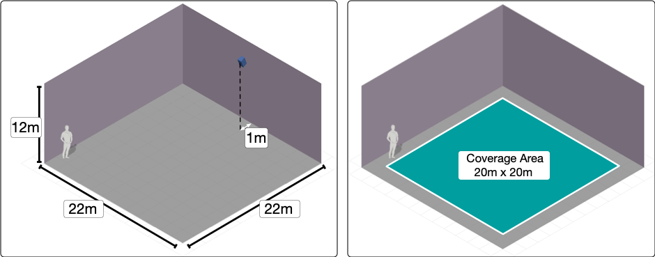
Example Room – Dimensions and Loudspeaker Perimeter (left), Coverage Area (right)
Go Distance: 1/4 the distance of the narrow side of the Coverage Area (20 m x 0.25 = 5 m).
Go Zone: Subtract 1x “Go Distance” (5 m) from all sides and elevate to ear height of the listeners (1.5 m). The narrow side of the Go Zone is 2x the Go Distance (10 m). In this square room, the Go Zone is 2x the Go Distance square (10m x 10 m).
Note
The Go Zone and Go Distance provide a scalable reference for identifying loudspeaker locations and do not define the immersive experience area. The immersive experience area can be as large as the loudspeaker parameter, if the loudspeaker positions and loudspeaker directivity are optimal.
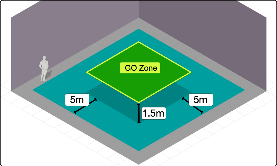
Example Room – Dimensions and Loudspeaker Perimeter (left), Coverage Area (right)
Main system
To meet the design goals for this example, the Main loudspeakers should have a narrower vertical and wider horizontal coverage. Beyond directivity, bandwidth and SPL needs to reproduce the desired signals versus the loudspeaker capabilities should be considered.
Main System Horizontal Spacing:
Spread the loudspeakers to fill a length of 2x the Go Distance (10 m).
Example 1: Three Mains Scenario – Spread the mains horizontally to fill a length of 2x Go Distance (10 m), horizontal spacing of 5 m. The outer mains are in line with the edges of the Go Zone.
Example 2: Five Mains Scenario – Spread the mains horizontally to fill a length of 2x Go Distance (10 m), horizontal spacing of 2.5 m
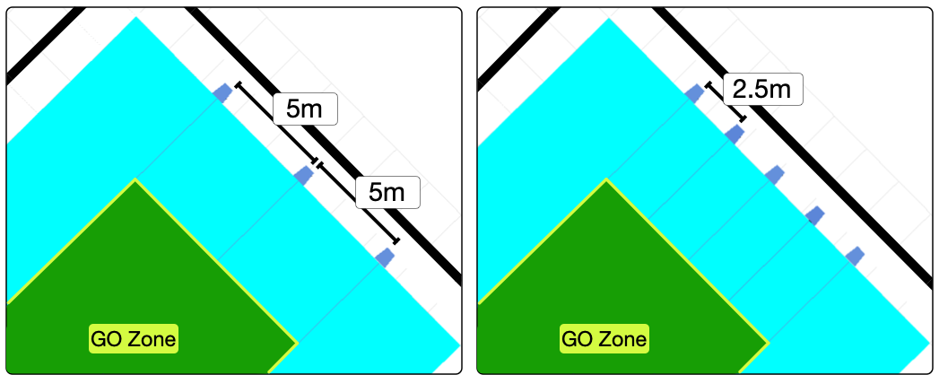
Main System – Three and Five Loudspeakers
Example 3: If using higher SPL models as primary Left/Right anchors, with lower SPL models used in secondary positions: spread the loudspeakers horizontally to fill a length of 2x Go Distance (10 m). Use the outer positions or the second and forth positions for the Left/Right anchors.
Main System Height:
Maximum: One Go Distance above the Go Zone (5 m), less than 45° downtilt to closest edge of Go Zone.
Minimum: 1/2 Go Distance above the Go Zone (2.5 m).
Usually, maximum height yields the most uniform coverage.
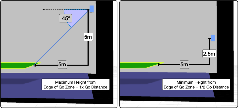
Main System – Maximum and Minimum Height
Mains Coverage Verification
One way to simplify verification of loudspeaker coverage, is to adjust the SPL preferences in MAPP 3D:
To make coverage easier to identify, change the preferences in FILE > PROJECT SETTINGS, SPL Tab to be ATTENUATION mode, Range = 12 dB, 6 dB/color.
Set the Prediction Parameters to 1 Octave, 4kHz. This frequency range is representative of the high-frequency coverage of most loudspeaker models.
The prediction data in red represents 0 dB to -6 dB of attenuation and we will call that “in coverage.” The Go Zone should be completely red or very close to it.
Note
All MAPP 3D predictions below use these settings unless otherwise stated.
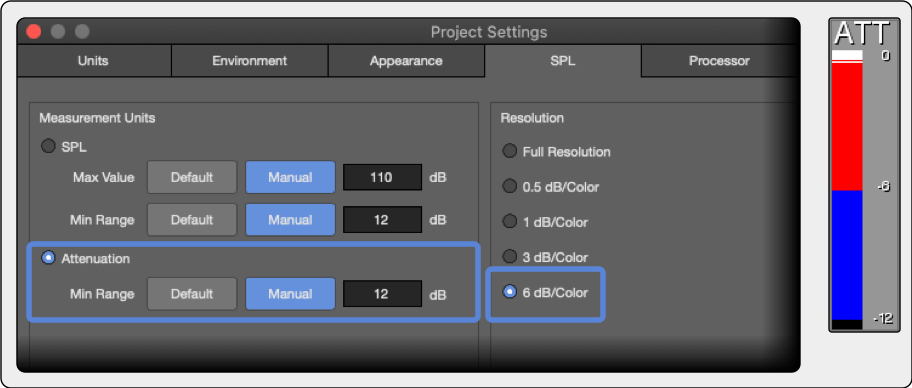
MAPP 3D Project Settings, SPL Tab, Attenuation Settings
Ideally, each loudspeaker provides the same coverage for each audience location. Because that is not realistic, we work towards that goal. Spill outside the Go Zone is great! But, if the walls above listener height are in coverage, consider a loudspeaker model with a narrower pattern. If a loudspeaker model provides less than 75% coverage in the Go Zone (relative, 0 dB to -6 dB), use a loudspeaker with different directivity or change the height and aim.
Example 1: The ULTRA‑X40 (110° vertical x 50° horizontal ) at the maximum height (6.5 m, 1.5 m listener height + 5 m Go Distance), provides uniform coverage from each main position for this space (below).

Main System Coverage Verification – Good Go Zone Coverage Achieved (ULTRA‑X40, 110° Horizontal)
Example 2: With the ULTRA‑X40’s in the same location and the horns rotated (50° horizontal x 110° vertical), the coverage is insufficient, below.

Main System – Insufficient Coverage, ULTRA‑X40 Horns Rotated to 50° Horizontal
Example 3: As the height of the center loudspeaker is changed, the coverage is affected. The downtilt is adjusted for each height, always at the opposite edge of the coverage area. The coverage area decreases as loudspeaker height is lowered from 1x Go Distance (5 m) to 1/2x Go Distance (2.5 m).

Main System – Maximum, Middle, and Minimum Height Effects Coverage
Lateral system
Like the mains, select models with wide horizontal coverage and more narrow vertical coverage.
Lateral System – Power Scaling
The maximum SPL output of a loudspeaker in the Go Zone is dependent on your relative power needs. It is a decision based on creative needs – what sound needs to be reproduced at what maximum level? If the surrounds must reproduce signals at the same level as the mains – then they require an equal power scale. If the surrounds need to only supplement the mains, they can be 6 to 12 dB less in power scale or more, depending on the desired SPL.
Example 1: Leopard Mains – equal power = ULTRA‑X40 surrounds, reduced power = ULTRA‑X20
Example 2: ULTRA‑X40 mains – equal power = ULTRA‑X20 surrounds, reduced power = UPJ‑1P
Lateral System – Height (same as main system)
Maximum: One Go Distance (5 m) above Go Zone (1.5 m), less than 45° downtilt to closest edge of Go Zone.
Minimum: 1/2 Go Distance (2.5 m) above Go Zone (1.5m).
Lateral System, Sides – Horizontal Spacing
Locate first and last Side Surround 1/2 Go Distance beyond the Go Zone (5 m / 2 = 2.5 m).
Nominal spacing for the Side Surrounds is the Go-Distance (5 m). Fill between first and last Side Surround at evenly spaced intervals, not exceeding 1x Go Distance.
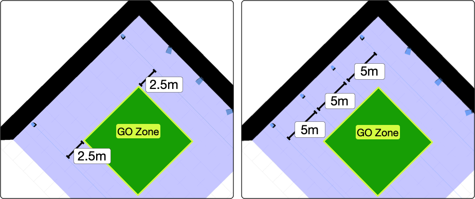
Lateral System, Side Locations – First and Last 1/2 Go Distance Outside Go Zone (left), Fill Between (right)
Lateral System – Aiming: (same as Main System)
Pan (horizontal) to middle of Go Zone
Tilt (vertical) to opposite Loudspeaker Perimeter.
Note
The center lines of the Meyer Sound HMS models from the CINE-STUDIO Series differ slightly from the center of the acoustic output: HMS‑15 and HMS‑10 aim 2°‑low, HMS‑5 aim 2°‑higher.

Lateral System, Sides – Pan to Center of Go Zone, Downtilt to Opposite Loudspeaker Perimeter
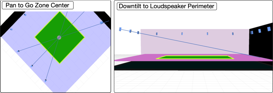
Lateral System, Rears – Pan to Center of Go Zone, Downtilt to Opposite Loudspeaker Perimeter
Lateral Coverage Verification
Use the same verification method for the side and rear laterals as was used for the mains: target the Go Zone and cover as much of the entire space as possible without covering the walls above listening height. If coverage is not sufficient, adjust the height and downtilt and/or try another loudspeaker model.
Example 1: The ULTRA‑X20 (110° vertical x 50° horizontal ) at the maximum height (6.5 m, 1.5 m listener height + 5 m Go Distance), provides uniform coverage of the Go Zone from each Lateral Side position for this space.

Lateral System, Sides – Coverage Verification, Good Go Zone Coverage Achieved (ULTRA‑X20, 110° Horizontal)
Overhead system
These positions will benefit from a model selection that has both a wide horizontal and vertical coverage pattern.
Overhead System – Power Scaling
The maximum SPL output of a loudspeaker in the Go Zone is dependent on your relative power needs. If the overheads must reproduce signal at the same level as the mains – then they must have equal power scale. If the overheads need only supplement the mains, then they can be 6 to 12 dB down in power scale.
Example 1: Leopard Mains – equal power = ULTRA‑X40 surrounds, reduced power = ULTRA‑X20
Example 2: ULTRA‑X40 mains – equal power = ULTRA‑X20 surrounds, reduced power = UPJ‑1P
Overhead System – Height
Maximum: 2x Go Distance (10 m) above the Go Zone (1.5 m)
Minimum: 1x Go Distance (5 m) above the Go Zone (1.5 m)
Tip
Maximum height usually provides more coverage area.
Overhead System – Horizontal Spacing
Locate loudspeakers above the corners of the Go Zone. On the long side of a rectangular room, if the distance between the Go Zone corners is between 1x and 2x Go Distances, consider adding a loudspeaker between the corners. If the distance is 2x Go Distances or more, add evenly spaced loudspeaker positions at 1x Go Distance spacing.
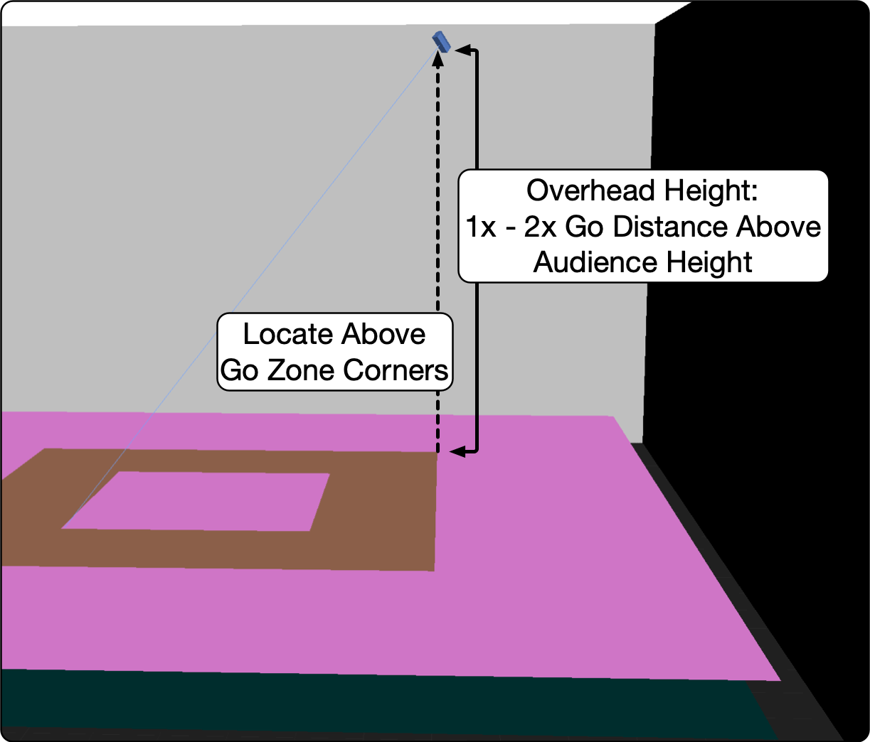
Overhead System – Locate above Go Zone Corners, Height Between 1x and 2x Go Distance
Overhead System – Aiming
Pan (horizontal) through middle of the Go Zone
Tilt (vertical) to 1/2 Go Distance past the center of the Go Zone.
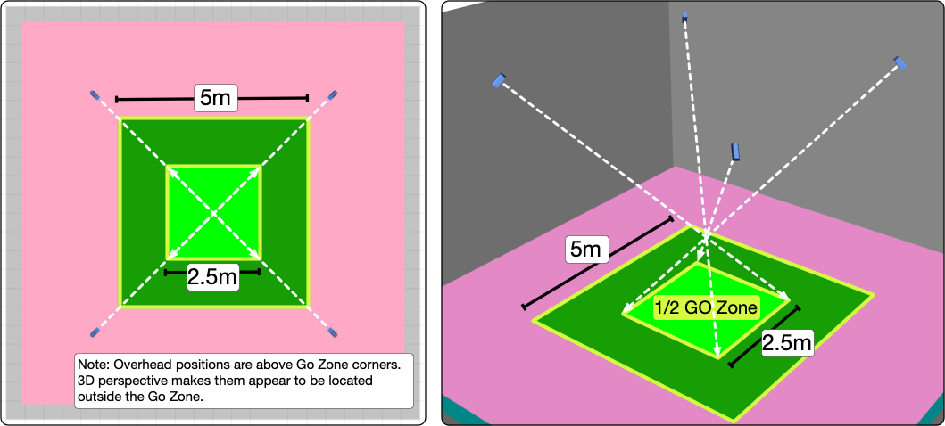
Overhead System Aiming – Pan Through the Go Zone Center, Tilt to 1/2 Go Zone Corners
Overhead Coverage Verification
Again, target the Go Zone and cover as much of the entire space as possible without covering the walls above listening height. Adjust the height or select another loudspeaker model if coverage is not sufficient.
Example 1: The ULTRA‑X23 (110° vertical x 110° horizontal) at the maximum height of 2x Go Distance (11.5 m, 1.5 m listener height + 2x Go Distance, 10 m), provides uniform coverage of the Go Zone from each Overhead position for this space.

Overhead System – Coverage Verification, Good Go Zone Coverage Achieved (ULTRA‑X23, 110° x 110°)
Low-frequency system
Low-Frequency Power Scaling
The maximum SPL output of a subwoofer is dependent on your relative power needs in lower frequencies when compared to the SPL capabilities of the mid-high loudspeakers. Usually, subwoofers used with the main mid-high system can reproduce at least the same in-band SPL as the mid-high models, but commonly more(e.g., 6 to 12 dB. Subwoofers used with the lateral and overhead system are usually scaled with the mid-high models used, may be extremely over-specified, or not used at all, depending on the expected content and maximum SPL needs.
Low-Frequency Locations
Because lower frequencies are more difficult to localize, fewer locations are required than the mid-high loudspeakers for effective low-frequency panning.
For the subwoofers paired with the main/front system, the scaling criteria and locations are the same as used with a typical system. Single elements or arrays are used, flown or ground stacked, to achieve coverage uniformity and SPL as desired. For the lateral and overhead systems, it is important to understand what the intended reproduction signals are, how loud they need to be reproduced, and the amount of localization desired. It may be that a single, lower-powered subwoofer on each side wall is sufficient for reproducing lower-level, atmospheric content while reproducing the sound of giant creature footfalls might require many positions and as much power as the main system subwoofers. Overhead subwoofers can be used to convincingly reproduce a sound that has low-frequency content above the audience.
Low-Frequency Examples
On the left, four subwoofers augment the output of the Main or Frontal System. Two subwoofers are located in the rear corners to augment the Side and Rear Systems. On the right, the Main Subwoofer Array is arranged in a spaced line and utilizes delay offset to increase the width of coverage, the outer pair is delayed 2 ms and the middle pair 1 ms, relative to the center subwoofer. The Overhead Subwoofer Array is directional. The rear element is polarity reversed, delayed 2.9 ms, and is 1 m above the bottom element. Spacemaps can be created to pan between these arrays or individual elements within an array.
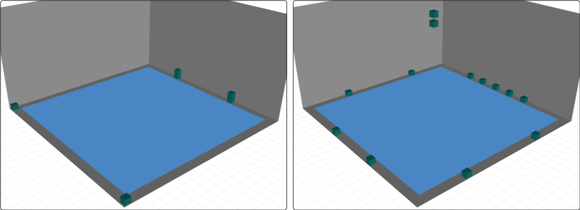
Subwoofer System – Less Localization (left), More Localization (right)
Signal processing channel assignments
For maximum panning control, each GALAXY processor output is connected to an individual loudspeaker or an array of loudspeakers. When one processor output is connected to multiple loudspeakers, panning between the loudspeakers is not possible. If panning within an array is not needed, a single Spacemap Go processor output can be used as an input, routed to several outputs connected to an array, and/or used for inner-array optimization.
Variations of room geometry
This design method is also used for rooms that are not square. Find out how in this video: SMG System Design Roundtable #2 that includes design examples for non-square rooms, design strategies used with balconies and fills, and concludes with several Spacemap examples.
00:00-10:00 Review of the Above Design Methodology
10:00-41:30 Design Methodology in Non-Square Rooms
41:30-end Example Spacemaps
DiGiCo Spacemap Go plugin
DiGiCo and Meyer Sound Laboratories have worked in partnership to provide integrated control of a Spacemap Go immersive loudspeaker system from Quantum and SD series consoles. Spacemap Channels can be associated with console Channels or Groups, with full control of Spacemap Panner, Crossfade, Spread and Trajectory transport controls available from the console for each Spacemap Channel. The control view also provides the Channel name, both Spacemap names, and the trajectory name if active.
The Spacemap Server runs on the Galileo GALAXY network platform processor, and the Spacemap Go app, as well as all external controllers that are connected as clients to the Spacemap server.
Software and firmware requirements
This feature is available when using the following software and firmware versions, or more recent releases:
DiGiCo Console software V1742
Meyer Sound Compass version 4.13.1, which includes Meyer Sound GALAXY firmware version 2.8.1
Meyer Sound Spacemap Go version 1.2.2, available at the Apple App Store
System configuration in the Spacemap Go app
Using the Spacemap Go app, navigate to the SETTINGS VIEW. In the left pane, select EXTERNAL DEVICE CONNECTION. In the right pane, in the SPACEMAP SYSTEM IP CONFIGURATION fields (top of pane), enter an IPv4 address for the Spacemap system and a Subnet Mask to establish a communication path to/from the DiGiCo console (e.g., IPv4 address 192.168.1.10, subnet mask 255.255.255.0).
See this FAQ for additional Spacemap system Galileo GALAXY processor IPv4 addressing information.

Spacemap Go app - Settings view, External Device Connection, Spacemap System
In the same pane (EXTERNAL DEVICE CONNECTION), scroll down to CONSOLE, tap ENABLE, and enter the console's IPv4 address in the EXTERNAL DEVICE (CLIENT) IPv4 ADDRESS field.
Note
See Configure Console, Step 2 for console IPv4 address information.
Each IPv4 address on the network must be unique, but in the same subnet for successful communication between Galileo GALAXY and the console (e.g., 192.168.1.100, 192.168.1.110, using the subnet mask 255.255.255.0)
In the EXTERNAL DEVICE (CLIENT) RECEIVING PORT field, enter the port number for the Spacemap system to receive communication from the SSL console. The suggested port number is 4001.

Spacemap Go app – Settings view, External Device Connection, Console
Note
This connection is exclusive, meaning that the Spacemap server will only accept messages arriving from the entered IPv4 address of the console, and will only reply or update the console at that address.
Configure the console
Navigate to the DiGiCo console’s EXTERNAL CONTROL options tab (MASTER SCREEN > SETUP > OPTIONS). In the Channel Controllers panel, select SpaceMap.
DiGiCo console – External Control options, OSC
In EXTERNAL DEVICES, select add device, and then select other OSC from the drop-down menu. Enter a Name, and then in the IP ADDRESS field, enter the IPv4 address of the Spacemap System.
Note
The console’s IPv4 address is displayed at the bottom of the dialog for reference and must be in the same subnet as, but not identical to, the IPv4 addresses of the devices running Compass and the Spacemap Go app. See model-specific documentation at digico.biz.
Verify the console IPv4 address has not changed when the console is power cycled.
In the SEND field, enter the Spacemap System OSC Port number (38033), in the RCV field enter the same port number entered in the Spacemap Go app, EXTERNAL DEVICE (CLIENT) RECEIVING PORT (default is 4001). Then enable control by clicking on the Enabled field.
Path assignment
Control of a Spacemap Go Channel can be enabled on any of the console’s Channel or Groups paths. Navigate to the channel, and open the Controller view by tapping on CHANNEL > GROUP ASSIGNMENT, at the bottom of the popover window enable Spacemap Controller, and then View. Close the popover and click on the 2D XY Panner, the external controls will appear. The assigned Spacemap channel can be changed by clicking on the blue box with the currently assigned Spacemap channel in white.
DiGiCo Console Path Assignment
Audio routing
Ensure the console and GALAXY Processor sample rates are compatible. Set the console output sample rate to either 96 kHz (recommended) or 48 kHz. If the console output is 48 kHz, engage the AES ASCR (asynchronous sample-rate converter) option for the Galileo GALAXY input(s) in Compass software ({processor name} > SETTINGS > INPUT AND OUTPUT). If the console output is set to 96 kHz, ASCR’s are not needed, but won’t have an adverse effect. The internal sample rate of GALAXY processors is 96 kHz. Also, refer to model-specific documentation at digico.biz for details.
GALAXY Processors support analog, AES3, and AVB inputs. Route the console’s Channel/Stem outputs to the required ports for connection to the Meyer Sound GALAXY processor. Please refer to the Routing section for further information.
Note
The recommended routing is to use the Channel/Group direct outputs as inputs to the Spacemap system. Set the outputs to POST ALL processing (see model-specific documentation at digico.biz).
Available controls
When the Spacemap Go Control is enabled on a Channel or Group, the path’s SPACEMAP CONTROL VIEW of each Channel or Group presents the Spacemap Go control interface. This provides control of the following parameters for the associated Spacemap Go Channel:
X/Y of Spacemap Panner
Crossfade
Spread
Trajectory Rate
Trajectory Transport Controls
A 2D panning interface is provided for touch control of the X/Y position of the Spacemap Panner for the assigned Spacemap Channel.
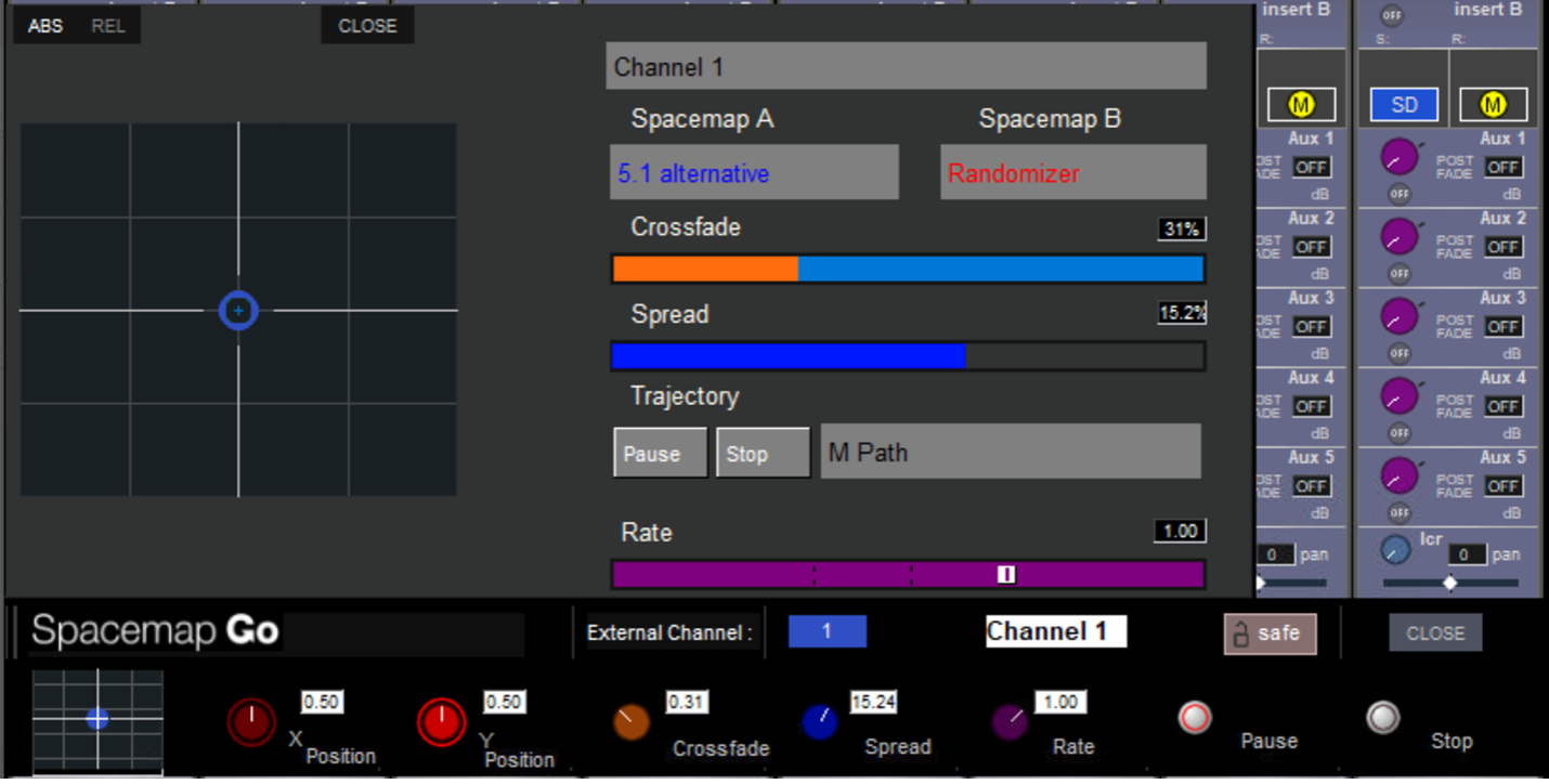
DiGiCo console – Spacemap Go interface
Avid VENUE plugin
Software and firmware requirements
This plugin requires the following software and firmware versions, or more recent releases:
Avid VENUE | S6L consoles running Version 7 software
Meyer Sound Compass version 4.9.2, which includes Meyer Sound GALAXY firmware version 2.4.2
Meyer Sound Spacemap Go version 1.2.0, available at the Apple App Store
Plugin installation
Download the plugin, unzip it, and copy the SpacemapControllerForVENUE.aaxplugin file to a USB drive.
At the Avid VENUE console, click EXIT TO DESKTOP by holding down CTRL + the shutdown command.
Connect the USB drive to the console and add the
SpacemapControllerForVENUE.aaxplugin file to this directory:Step 4: Launch the VENUE 7.0 software. Click OPTIONS, then the PLUG-INS tabs.

Avid Console – Exit to Desktop
From the DEVICE drop-down, select CONSOLE from the drop-down menu.
In the PLUG-INS TO INSTALL list, click to select SpacemapControllerForVENUE.
Click INSTALL.
Once installed, the plugin will be listed in the INSTALLED PLUG-INS list (Result, below).
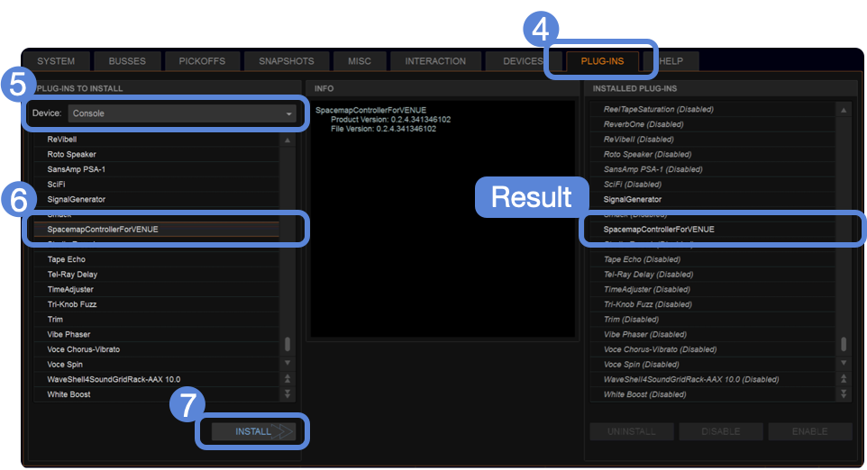
Avid Console – Options > Plug-Ins Tab, Select Device = Console, Select Spacemap Plugin, Click Install
Physical connections
Connect the ECx NIC to the same Ethernet network as the GALAXY processors in Spacemap mode.
Note
Spacemap Go commands are sent from the console ECx Ethernet NIC. MILAN AVB streams are sent from the console via the installed MLN-192 card(s) NICs.
Load the plugin to a console channel
The Spacemap plugin is loaded to a channel in the same way other plugins are.
Select the PLUG-INS tab.

Avid Console – Plug-Ins Tab
Select MONO or STEREO.
Select SOUND FIELD.
Select SPACEMAP GO PLUGIN.
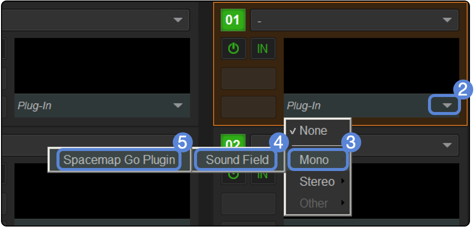
Avid Console – Plug-In Tab, Select Plugin
Select a console channel or output to assign this plugin instance to.
Note
This step does not make the audio connection to the Spacemap system. The audio of the channel must be delivered to the intended Spacemap system input and, using Spacemap Go, assigned to the proper Spacemap Go channel.
The plugin can be assigned to any channel that can host a plugin (e.g., Input Channels, Groups, Aux Sends, etc.). The SELECT button of the channel will recall the plugin and populate the CKM module above the fader bank of the channel.
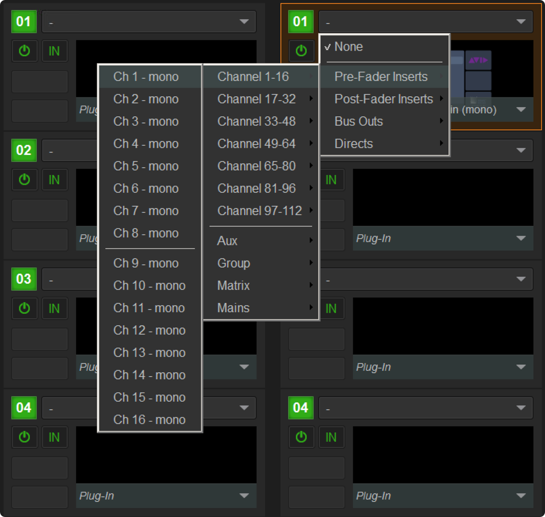
Avid Console – Plug-In Rack, Assign Plug-In to a Signal Path
Double-click the Plug-In Rack to open the plugin interface.
On the Connection page, select which Spacemap system to connect with the plugin.
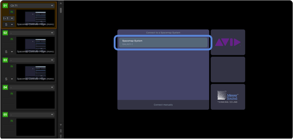
Plug-In Connection – Select Spacemap System, Click on System Name
Generally, it is not necessary to connect the plugin to the Spacemap system manually, but in case it is, click CONNECT MANUALLY at the bottom of the Connection page and enter the IPv4 address of the Spacemap system. By default, the Spacemap system uses IPv6 addressing, but the system can be assigned an IPv4 address in the Spacemap Go app by navigating to SETTINGS VIEW > EXTERNAL DEVICE CONNECTION > SPACEMAP SYSTEM IP CONFIGURATION and entering an IPv4 address in the same subnet as the VENUE console. See this FAQ for additional Spacemap system GALAXY processor IPv4 addressing information.
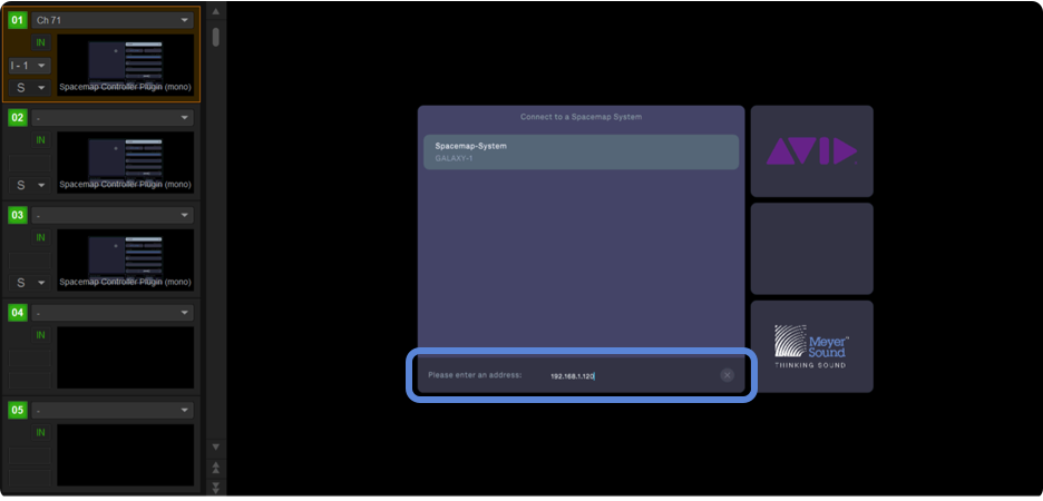
Plug-In Connection – Enter the IPv4 Address of a Spacemap System Address
Select the Spacemap Channel for the plugin to control by clicking the Channel button in the upper right of the plugin and select a channel from the drop-down menu.
Note
The Channel selection enables control of the parameters of the selected Spacemap Channel, the Spacemap System Mix Level, and System, Mix, and Channel Snapshot recalls.
Selecting NONE for the Channel selection limits the instance of the plugin to control only the Spacemap System Mix Level and recall of Spacemap Go Snapshots. This can help separate global controls and channel controls at the console.
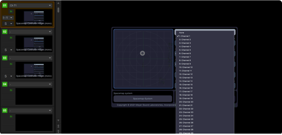
Plug-In Connection – Select the Spacemap Channel to Control with the Plug-In
Plugin controls
These controls can be modified on screen and are visible in the CKM channel when the console channel is selected:
X-Y Position
Crossfade between Spacemaps of a Spacemap Channel
Spread
Trajectory Start, Pause, and Stop
Trajectory Rate
Spacemaps are not displayed in the plugin. The Spacemap and Trajectory names are read only in the plugin. Use the Spacemap Go app to select different Spacemaps or Trajectories, or use the plugin to recall Spacemap Snapshots that have different Spacemaps or Trajectories assigned to a Spacemap Channel. The Spacemap Snapshots can then be recalled using the plugin.
All controls can be modified on the screen by click-dragging the controls available in the plugin, e.g., the Spacemap Panner, Crossfade and Spread sliders, Trajectory buttons, and Rate slider.
Use the Spacemap Go app to change/edit all names displayed in the plugin.
The Setlist and System Controls at the bottom of the plugin are described in the Snapshot Control section below.
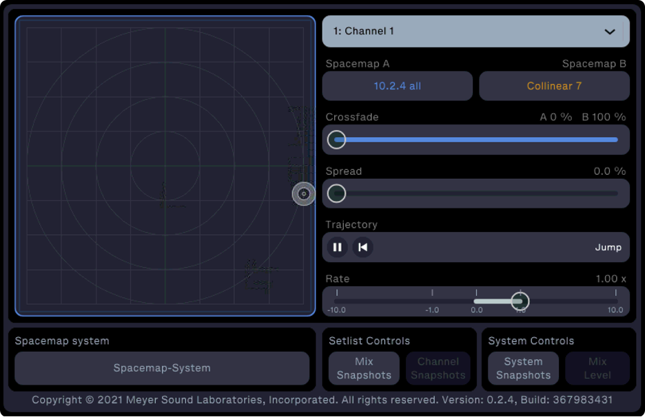
Spacemap Plugin Available Controls
CKM controls
The CKM module displays the plugin controls for the selected channel of the console.
The first two columns (Console Channel Plugin Control, below) relate to the console channel plugin rack.
The last three columns (Spacemap Global Controls, below) control global Spacemap Go functions: Mix Level and Snapshot recall.
These controls are the same as those displayed in the plugin. The settings are displayed in the OLED screen and are controlled by the corresponding rotary knob. Depressing the rotary knob has no function.
Mix Level controls the output level of the entire Spacemap system. The other global Spacemap functions are explained in the Snapshot Recall section below.
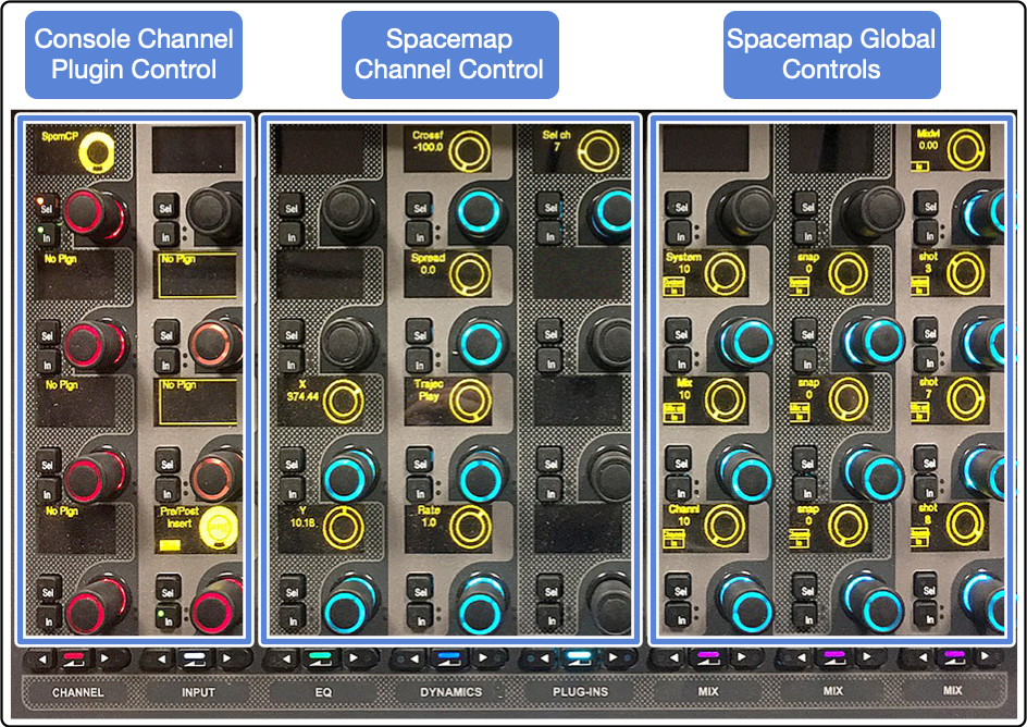
CKM Spacemap Plugin Controls
Snapshot recall
Spacemap snapshot external ID value
In Spacemap Go, the External Recall ID numbers for each Snapshot are displayed in the Setlist view by tapping the three-dot icon  next to each Snapshot.
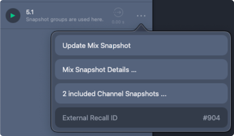
Spacemap Go App, Setlist View – Details of Snapshot, Including External Recall ID Number
Enable setlist and system controls
For Snapshot recall, two options are available: manually using the CKM module controls or storing the state of the plugin with a console snapshot. Both require the Setlist and System Controls for the instance of the plugin to be enabled in the plugin interface.
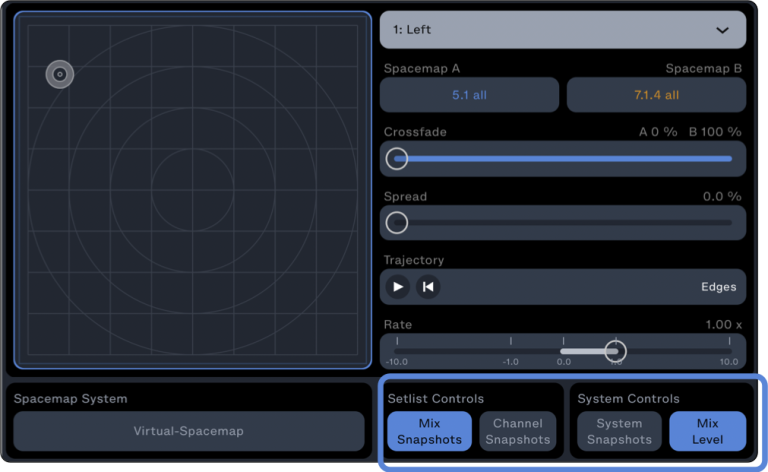
Spacemap Go Plugin – Setlist Controls, Mix Snapshots Enabled and System Controls, Mix Level Enabled
Manual recall
The CKM module displays the active Snapshot Recall ID number in each of the last three rows of the last three columns of the module. The Mix Snapshot is highlighted below.
Due to the resolution of the encoders, the Recall ID value has been split into the three columns: hundreds, tens, and ones. For example, to recall Snapshot #1248, set the encoders to 12, 4, and 8.
To change a value, press the IN button next to the rotary knob.
Use the rotary knob to change the value(s).
Within 5 seconds, press the SEL button next to the rotary encoder to send the updated value to the Spacemap system.
The SEL and IN button LEDs will turn off and the updated value will be displayed.
Note
When a value is changed using the rotary knob, the SEL button times out after 5 seconds and the current value is displayed. If SEL is not pressed within 5 seconds, the value will revert to the current Spacemap value.
In the left image below, the IN button has been pushed and the rotary knob is used to change values to be sent to the Spacemap system.
In the right image below, the SEL button is also illuminated and Mix Snapshot #1005 is ready to be recalled. When the SEL button is pressed within 5 seconds, the command to recall Mix Snapshot #1005 is sent to the Spacemap system.
Note
Remember that a Mix snapshot should always be recalled before a Channel Snapshot. System snapshots can be recalled at any time.
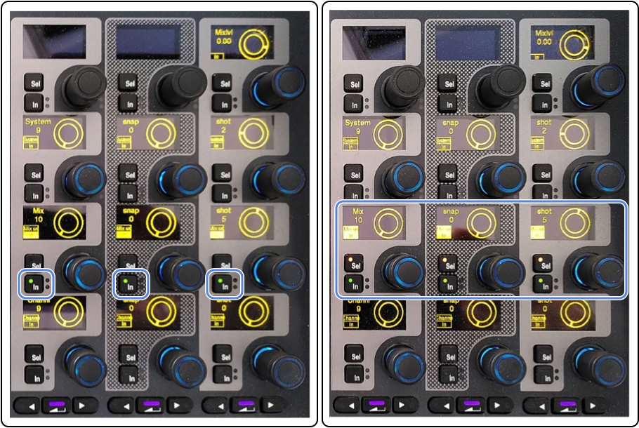
Console CKM Display – Global Spacemap Controls Section, Snapshot ID #1005 Ready for Recall
Automation recall
The plugin state needs to be stored with the Console Snapshot. To do this, go to the instance of the plugin that will control the Snapshot recall and either:
Create a new console Snapshot, including the Spacemap Plugin, or
UPDATE or ADD the plugin to a Target Snapshot > console_snapshot_name here >
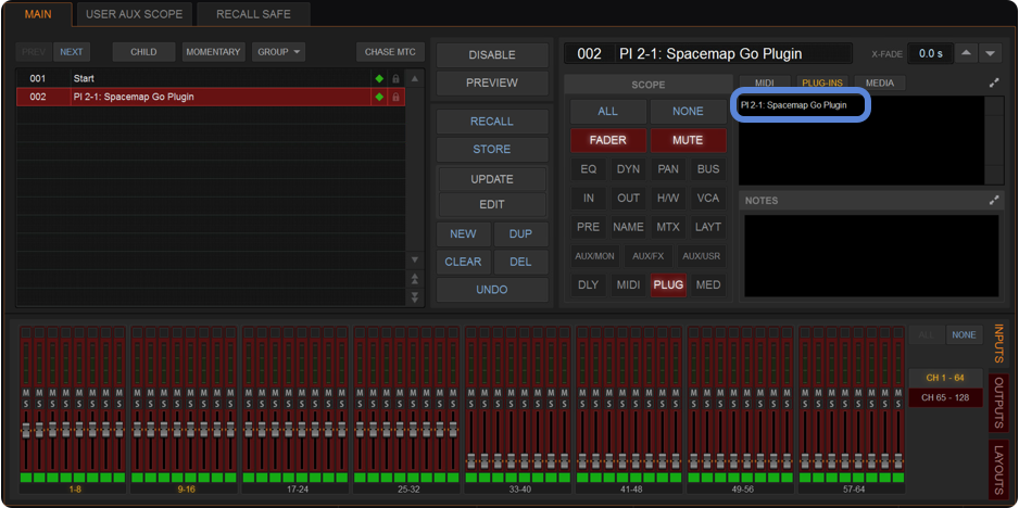
Avid Console – Create Console Snapshot Including Spacemap Plugin
Plugin control can be integrated with the Console Snapshot recalls. At this time, the plugin stores the current Spacemap Snapshot Recall ID number displayed on the CKM. It is not affected by manual control.
The plugin controls at the bottom must be enabled to trigger Snapshots. The state of these controls is also stored with a Console Snapshot.
When stored with a Console Snapshot, the plugin state includes:
The state of the Global controls (if recall is enabled or not).
The current Spacemap System Snapshot.
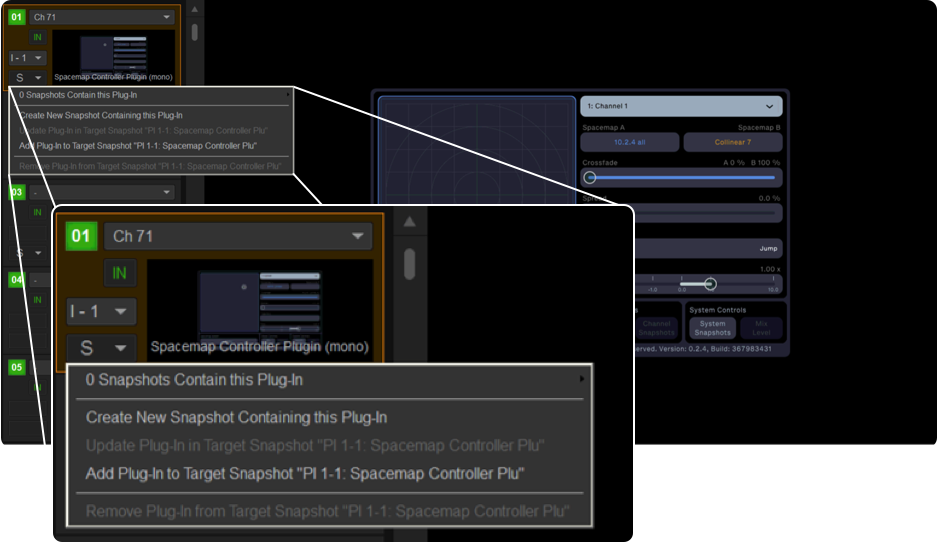
Avid Console – Console Snapshot Including Spacemap Plugin State
Recommended workflow
Assign instances of the plugin to console inputs or outputs for control of associated Spacemap Channels. For these instances, disable the Setlist and System Controls.
Assign one instance of the plugin to an otherwise unused console channel, expressly for the purpose of making manual or automated changes to the Global Spacemap controls, Mix Level, and Snapshot recalls. This strategy minimizes the likelihood of multiple instances of the plugin making changes to Global Spacemap controls.
Note
The plugin can be assigned to a Console Channel, using NONE as the selected Spacemap Channel, enabling only Mix Level and Spacemap Snapshot recall controls.
In the Spacemap Go app, after Spacemap Snapshots are created and the Setlist is established, recall the first Snapshot.
From the Plug-In tab of the Console, choose the instance of the plugin that will control Snapshots.
Create a new Console Snapshot from the Plug-In Rack using the S drop-down menu in the bottom-left corner (see above).
In the Spacemap Go app, recall the next Snapshot from the Setlist view.
Create a new Console Snapshot from the Plug-In Rack using the S drop-down menu in the bottom-left corner (see above).
Repeat for additional Spacemap Snapshot recalls.
SSL Spacemap Go plugin
Meyer Sound Laboratories, Incorporated and SSL have worked in partnership to provide integrated control of a Spacemap Go immersive loudspeaker system from the console interface. Spacemap Channels can be associated with console Channels or Stems, with full control of Spacemap Panner, Crossfade, Spread and Trajectory transport controls available from the console for each Spacemap Channel.
Software and firmware requirements
This feature is available when using the following software and firmware versions, or more recent releases:
SSL Live console software version 5.0
Meyer Sound Compass version 4.9.2, which includes Meyer Sound GALAXY firmware version 2.4.2
Meyer Sound Spacemap Go version 1.2.0, available at the Apple App Store
Configure the Spacemap Go app
Using the Spacemap Go app, navigate to the SETTINGS VIEW. In the left pane, select EXTERNAL DEVICE CONNECTION. In the right pane, in the SPACEMAP SYSTEM IP CONFIGURATION fields (top of the pane), enter an IPv4 address for the Spacemap system and a Subnet Mask to establish a communication path to/from the SSL console (e.g., IPv4 address 192.168.1.10, subnet mask 255.255.255.0). See this FAQ for additional Spacemap system GALAXY processor IPv4 addressing information.

Spacemap Go App – Settings View, External Device Connection, Spacemap System
In the same pane (EXTERNAL DEVICE CONNECTION), scroll down to CONSOLE, tap ENABLE, and enter the console’s IPv4 address in the EXTERNAL DEVICE (CLIENT) IPv4 ADDRESS field.
Note
The IPv4 address of the console is displayed and changed in the console’s Network Options (MENU > SETUP > NETWORK).
Each IPv4 address on the network must be unique but in the same subnet for successful communication between devices (e.g., 192.168.1.100, 192.168.1.110, using the subnet mask 255.255.255.0)
In the EXTERNAL DEVICE (CLIENT) RECEIVING PORT field, enter the port number for the Spacemap system to receive communication from the SSL console. The suggested port number is 4001.

Spacemap Go App – Settings View, External Device Connection, Console
Configure the console
Navigate to the SSL console’s EXTERNAL CONTROL options tab (MENU > SETUP > OPTIONS). In the OSC SETTINGS panel, select SPACEMAP GO in the device list to open the DEVICE CONFIGURATION panel.
Figure 2.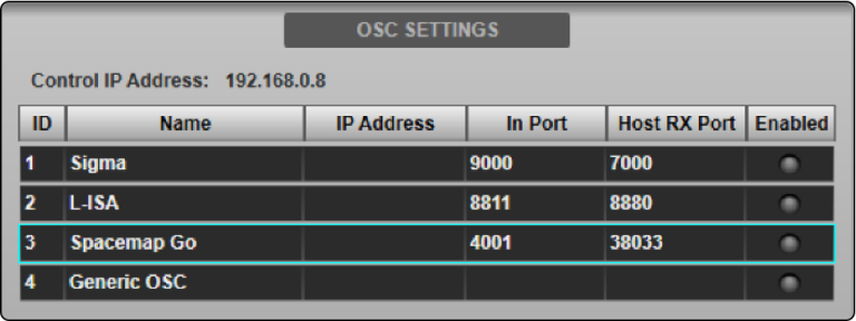
In the DEVICE CONFIGURATION panel, HOST IP ADDRESS field, enter the IPv4 address of the computer running Compass software.
In the INCOMING PORT field, enter the same port number entered in the Spacemap Go app, EXTERNAL DEVICE (CLIENT) RECEIVING PORT.

SSL Console – Device Configuration Panel
In the OSC SETTINGS window, tap ENABLE CONTROL to enable control of Spacemap Go from the console.
The ENABLED indicator in the OSC SETTINGS panel for Spacemap Go will turn green. Multiple devices can be enabled simultaneously.
Note
The console’s IPv4 address is displayed for reference and must be in the same subnet as, but not identical to, the IPv4 addresses of the devices running Compass and the Spacemap Go app. These addresses can be changed in the NETWORK options tab (MENU > SETUP > NETWORK OPTIONS tab; see Network Options for more details.
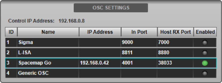
SSL Console – OSC Settings Panel, Spacemap Go Enabled
Navigate to the EXTERNAL CONTROL, Detail View page and select Spacemap Go from the SELECTED DEVICE menu.
Path Link can be used to assign and enable Spacemap Go control to multiple paths simultaneously. The selected External Control device will be stored in the console’s Showfile.
Ensure the console and GALAXY Processor sample rates are compatible. Set the console output sample rate to either 96 kHz (recommended) or 48 kHz. If the console output is 48 kHz, engage the AES ASCR (asynchronous sample-rate converter) option for the input(s) in Compass software ({processor name} > SETTINGS > INPUT AND OUTPUT). If the console output is set to 96 kHz, ASCR’s are not needed, but won’t have an adverse effect. The internal sample rate of GALAXY processors is 96 kHz. Also, refer to Clocking > Sync for details.
GALAXY Processors support analog, AES3 and AVB inputs. Route the console’s Channel/Stem outputs to the required ports for connection to the Meyer Sound GALAXY processor. Please refer to the Routing section for further information.
Note
The recommended routing is to use the Channel/Stem direct outputs as inputs to the Spacemap system. Set the outputs to POST ALL processing. Please see System Options for further details.
Available controls
When the Spacemap Go plug-in is enabled on a Channel or Stem, the path’s EXTERNAL CONTROL DETAIL VIEW presents the Spacemap Go control interface. This provides control of the following parameters for the associated Spacemap Go Channel:
X/Y of Spacemap Panner
Crossfade
Spread
Trajectory Rate
Trajectory Transport Controls
A 2D panning interface is provided for touch control of the X/Y position of the Spacemap Panner for the assigned Spacemap Channel.
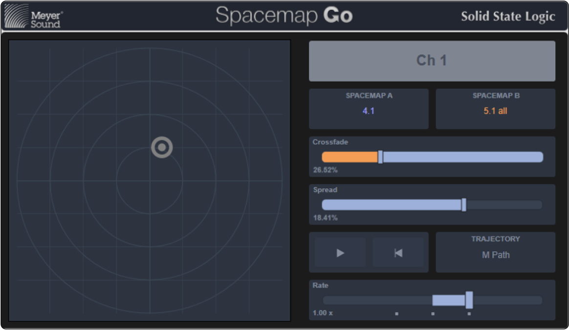
SSL Console – Spacemap Go Plug-In
The Spacemap Go iPad app takes control precedence. The console plug-in controls will be temporarily disabled while parameters are adjusted in the Spacemap Go app.
Important
It is recommended by SSL and Meyer Sound that console automation of EXTERNAL CONTROL parameters is disabled for paths using Spacemap Go. Instead, automate the Spacemap Go parameters using Mix and Channel Snapshots in the Spacemap Go app. Spacemap Go Snapshots include optional wait and transition times.
However, Spacemap Go parameters can be automated in the same way as other path parameters; use the EXTERNAL CONTROL column in the Automation Filters page to adjust the store and recall scope.
All of the Channel’s/Stem’s regular processing and bus controls remain available and function as normal.
Configuring Spacemap Go master level control
Create one OSC Path for the Spacemap Go Mix Level control using the Console Configuration page (MENU > SETUP > CONSOLE CONFIGURATION). Refer to the Console Configuration information for further details about using this page.
Place the OSC Path on the console surface using the Layer Manager to assign it to a Fader Tile layer/bank. OSC Paths may also be assigned to the console’s Master Tile FOCUS and MAIN faders. Refer to the Master Tile section for further instructions.
Navigate to the OSC Path in the Channel View and double-tap the Eyeconix area at the bottom of the screen to open the Name/Eyeconix Detail View page.
Name and select a color for the OSC Path as desired (e.g., SMG Master).
Navigate to the EXTERNAL CONTROL DETAIL VIEW page and select Spacemap Go from the SELECT DEVICE menu. The OSC Path’s fader will synchronize to the Spacemap Go Mix Master level position and can now be used to adjust it.
Caution
Care should be taken if automating the fader position, as it can cause large changes in level. Like other path types, the OSC Path’s fader position can be stored in console automation, but as with the per-path Spacemap Go controls described above, it is recommended that External Control parameters are disabled in console automation.
Automating Spacemap Go parameters
To prevent possible data conflicts, Spacemap Go parameters should be stored in only one automation system, either in Spacemap Go (recommended) or in the console. To disable recall from the console’s automation system, navigate to the AUTOMATION page (MENU > AUTOMATION) and select the GLOBAL RECALL FILTERS page. Refer to the Automation Filters section for details.
Navigate to the paths that have Spacemap Go control enabled and ensure the External Control column is turned off for these paths.
Note
This will only disable recall of the External Control parameters. To disable storing these parameters, turn off the External Control column in the Global Store Filters page as well.
Using a generic OSC path to trigger Spacemap Go snapshots
To trigger Spacemap Go Snapshots in sync with firing console scenes, a Generic OSC device assigned to an OSC path can be used.
Configure the Generic OSC device with the same IP address and port numbers as the Spacemap Go plug-in configured above.
Configure one of the Generic OSC Faders with an OSC Address of /Console/recall/system.
Note
Spacemap Go Snapshots are automatically assigned an External Recall ID number between 900 and 3000. Set the Fader’s Min and Max fields to cover the number of snapshots required. Keep in mind the Fader is represented in percentage, so a range (Min and Max) of 900 to 1000 would mean that a 1 % change in Fader position equates to increasing the External Recall ID by 1 (starting at 900). For example, a Fader value of 42 % would equal Snapshot #942 (900+42).
Generic OSC Fader 1 is mapped to the physical fader when assigned to an OSC Path. Therefore, it is recommended that another fader number is used, so as to prevent accidental physical fader moves causing a snapshot change.
Create a new OSC Path in the Console Configuration page (MENU > SETUP > CONSOLE CONFIGURATION). Refer to the Console Configuration section for further details about this page.
Ensure that the OSC Path’s External Control parameters are set to STORE and RECALL in the console’s automation scenes. Refer to the Automation Filters section for details.
Place the new OSC Path on the console surface for ease of access using the Layer Manager or use the LAYERS button in the Channel View sidebar to gain access.
Navigate to the OSC Path in the Channel View and double-tap the Eyeconix area at the bottom of the screen to open the Name/Eyeconix Detail View page. Name/color the OSC Path as desired, e.g., SMG Snapshot.
Navigate to the EXTERNAL CONTROL DETAIL VIEW page and select GENERIC OSC from the SELECT DEVICE menu.
In each console scene you wish to recall a Spacemap Go snapshot, change the OSC Fader position to match the required Spacemap Go External Recall ID number, keeping in mind the offset and range (Min and Max) of values entered above. Remember to store this value in the console’s automation system so it is recalled when the scene is fired.
Tip
Tap on the OSC Fader to select it, then double-tap in the text field in the lower right corner of the DETAIL VIEW to envoke a keyboard to enter a specific value. Refer to the Detail View section for further details.
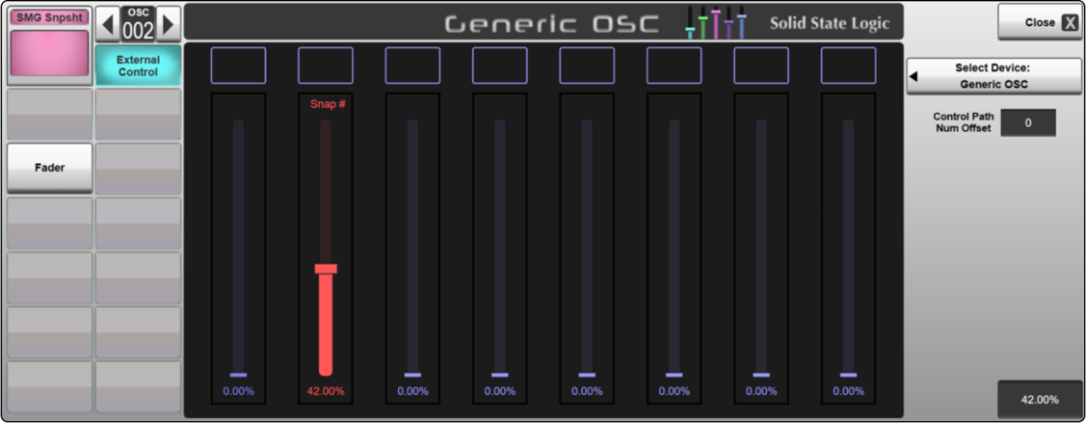
SSL Console – OSC Fader Set to Recall a Spacemap Go Snapshot
Now, when a scene is fired that contains a new value for the OSC Fader in the Generic OSC Path, an OSC message is sent to Spacemap Go, prompting a snapshot change to coincide with the console automation scene change.
DAW plugin
Plugin installation
Download the Spacemap Go VST3 and AAX plugin.
Unzip the file archive and launch the installer file Spacemap Go Plugin Setup.exe.
This file installs the VST3 and the AAX Spacemap Go plugin in the common files folder for plugins. If the DAW software is running, use the “re-scan for plugins” function of the DAW to update the available plugins.

Plugin Archive Contents, Windows OS – Launch Installer
Expand the archive file and launch the disk image file: Spacemap Go Plugin Setup.dmg
The Spacemap Go Plugin.pkg package installs the VST3, AU and AAX Spacemap Go plugin in the common files folder for plugins. If the DAW software is running, use the “re-scan for plugins” function of the DAW to update the available plugins.

Plugin Archive Contents, macOS X – Launch Installer
Using the plugin with a DAW
The following example uses Reaper software. The steps are similar for most DAW software. For specific DAW information, see user entries in the Spacemap Go section of the Forum (link also in the navigation menu at the top of this page).
Setup the Spacemap System using Virtual GALAXY processors (launched in Compass) or GALAXY processors. Use the Spacemap Go app to configure the Spacemap System; see Hardware Connections and Configure Galaxy pages under the START menu above.
In the DAW, add an instance of the plugin to any channel.

DAW – Add the Spacemap Go Plugin to Any Channel
The plugin will load and a control window opens displaying the Spacemap System connection page. Select the Spacemap System to control with the plugin.
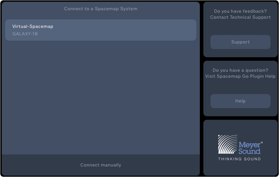
Spacemap Go Plugin – Select Spacemap System to Connect Plugin
Click CONNECT MANUALLY at the bottom of the window to enter the IPv4 address of a Spacemap System if an IPv4 address has been set for the system.

Spacemap Go Plugin – Set Manual IPv4 Address
In the plugin interface, use the Channel drop-down to select the Spacemap Channel this instance of the plugin will control.
Note
The assignment “None” controls global settings only (System, Mix, and Channel Snapshots, and Mix Level). Using different channels in the DAW can help separate Spacemap global controls and channel controls.

Spacemap Go Plugin – Select Spacemap Channel to Control with Plugin
Plugin controls
The Spacemap Go Plugin interface allows for direct control of the following Spacemap Go Channel parameters:
X/Y Panner Location, Crossfade, Spread, Trajectory Start, Pause, Stop, and Rate
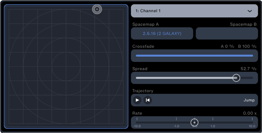
Spacemap Go Plugin – Available Channel Controls
The Channel Name, Spacemaps, and Trajectories are not modified using the plugin. These can be modified using the Spacemap Go app.
The global controls of the Spacemap System are located at the bottom of the plugin user interface. The left-hand button invokes the Spacemap Go Plugin Connection Page. The right-hand buttons enable recalling of the various Spacemap Snapshots and adjustment of the Mix Level. When the buttons are blue, the functions are enabled for the instance of the plugin.

Spacemap Go Plugin – Tap Spacemap System Name to Open Connection Panel (left), Recall Spacemap Go Snapshot
The Spacemap Go Plugin will send “Touch” commands to the DAW to write automation dynamically. The settings below will write the X and Y envelopes when the Spacemap Panner is moved in the Spacemap Go app, otherwise, the DAW will read the envelope values.
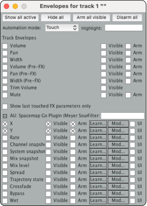
DAW – Available Automation Lane and Selections

DAW – Channel Envelope Points Recorded, Ready to be Played Back
Record snapshot recalls in the DAW
There are several methods to recall a Spacemap Go Snapshot from a DAW. One method is to set markers, that when passed, trigger OSC commands to recall Spacemap System, Mix, or Channel Snapshots. Another method is to use channel envelopes to either record Spacemap Snapshot recalls using the Spacemap Go app or to write channel envelopes manually:
Use the Spacemap Go app to establish the Snapshot order.
Using the DAW, set the track to WRITE and select the Snapshot type (System, Mix, or Channel).

DAW – Channel “Write” Enabled for Mix Snapshot
Right-click on the automation envelope and set the envelope default point shape behavior to SQUARE.
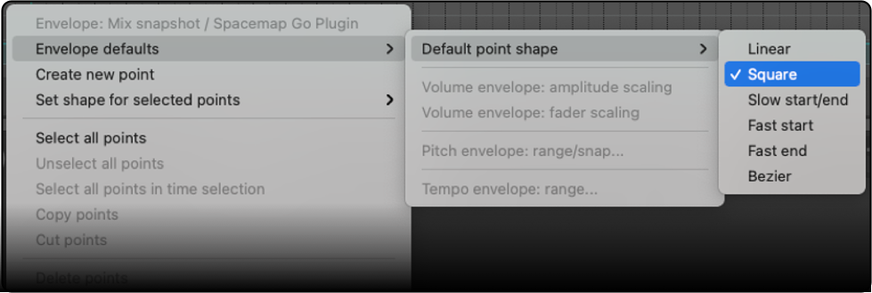
DAW – Set Point Shape to Square for Snapshot Recalls
Note
When using automation lanes to recall Spacemap Snapshots, avoid ramps between Snapshot recall ID values. The DAW will extrapolate all the values between the points, recalling many Snapshots instead of only the intended Snapshot.
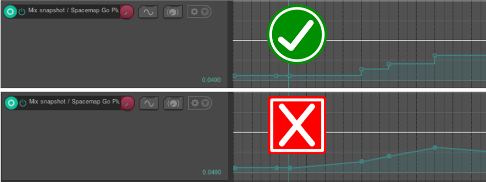
DAW – Square (above) and Linear (below) Mix Snapshot Recall Envelopes
In the DAW, play the track. Using the Spacemap Go app, recall Snapshots when desired. The envelope will update with the values.
In the DAW, set track to READ. In the Plugin, enable Snapshot recall. The envelope points can be edited for time and/or Snapshot Recall ID values.

Spacemap Plugin – Mix Snapshot Recall Enabled
Create snapshot recalls using the DAW
The recalling of Snapshots can also be written into automation lanes using the DAW. This allows for “offline” Snapshot recall programming and editing.
Make sure the intended automation lane (Mix, Channel or System Snapshot) is displayed for the track containing the plugin. The automation mode is not relevant at this point, but it will need to be changed to READ when playing back.
Create automation points using one of the methods below. Options, behaviors and shortcuts vary between DAW’s, but the basic steps are universal.
Option 1: Manually draw envelope breakpoints at (or close to) the desired points in the timeline. This is achieved in any DAW by either clicking, double-clicking or clicking with a modifier key in the automation lane field.

DAW – Manually Draw Snapshot Recall Envelope
Option 2: Create envelope breakpoints at the edge of the selection. This is usually achieved by either making a selection in the automation lane and then dragging the horizontal automation envelope up or down, or by clicking and dragging while holding specific modifier keys (e.g.,
OPT+SHIFT+CLICKandDRAGin Reaper/macOS). This method has the advantage of creating square edges at each end of the selection by default, avoiding the ramping issues mentioned above.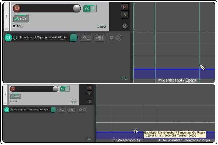
DAW – Create Envelope Breakpoints at Edge of Selection
Adjust the time and value of the envelope breakpoints by either clicking and dragging on the points, by clicking and dragging entire (horizontal) sections of the automation line, or by entering them in the Envelope Point (or similarly named) menu in your DAW. Please note that clicking and dragging might require modifier key(s) to be pressed in order to do fine adjustments to the values. Make sure the automation line is actually “square” (e.g., that successive breakpoints happen at the same moment in time and there is no ramping).
Note
The parameter value will always display the correct Snapshot ID when using the VST3 and AAX plugins. The AU version may have variable behaviors depending on the DAW used.
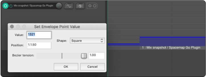
DAW – Edit the Time and Value of Breakpoints
Recommended workflow
Assign instances of the plugin to tracks for control of associated Spacemap Channels. For these instances, disable the Setlist and System Controls (lower-right of plugin). These controls are disabled by default. The buttons are grey when controls are disabled and blue when enabled.
Assign one instance of the plugin to an otherwise unused track, a bus track, or the master track, expressly for the purpose of making manual or automated changes to the Global Spacemap controls (Mix Level and Snapshot recalls). Enable the Setlist Controls and/or System Controls in the plugin. This strategy minimizes the likelihood of multiple instances of the plugin making changes to Global Spacemap Controls.
Note
The plugin can be assigned to a track, using NONE as the selected Spacemap Channel, allowing only Mix Level and Spacemap Snapshot recall controls.
In the Spacemap Go app, after Spacemap Snapshots are created and the Setlist is established, recall the first Snapshot.
In the DAW, use one of the above methods to create automation envelopes to recall Spacemap Snapshots.
Note
In some DAWs, all of a track’s envelopes are captured when the track is in Write, Touch, or Latch mode. Ensure that only the intended automation data is read during playback. For example, using envelopes to control the Panner X/Y position could conflict with a change in trajectory status because both will try to update the Panner position at the same time. The same conflict could exist when a Snapshot is recalled to start or stop a trajectory and an X/Y Panner move is in progress. We recommend avoiding instances where automation lanes make simultaneous changes that send the Spacemap system conflicting commands.
QLab
Hardware and software requirements
Galileo GALAXY processor booted into Spacemap Mode – requires firmware version included with Compass software version 4.9, or later which matches the version of the Spacemap Go app in use. This can be real hardware (required to pass audio) or a Virtual GALAXY running in Compass.
Computer running the latest OS and QLab versions.
Network Switch – AVB capable, Avnu-certified.
Spacemap Go receives OSC commands via port 38033 and QLab receives OSC commands via port 53000.
Connection steps: hardware (not virtual GALAXY)
The Apple computer and the GALAXY processor must be on the same network.
The Apple computer running QLab must be within the same IPv4 range and subnet as the Spacemap Go System IPv4 address, GALAXY processor(s), and iPad.
In the Spacemap Go app on the iPad, tap SETTINGS VIEW (bottom), then SYSTEM SETTINGS > EXTERNAL DEVICE CONTROL.
SYSTEM IP CONFIGURATION > IPv4 ADDRESS: Enter a system IPv4 address, in the same subnet of the computer running QLab.
Note
Spacemap Go uses this IPv4 address as the master IPv4 address of the system. Following that address, a contiguous range of IPv4 addresses for each Spacemap Go GALAXY processor is automatically assigned. These addresses are independent of the IPv4 addresses listed in Compass software on the PROCESSORS > SETTINGS > NETWORK tab.
Ensure the range of IPv4 addresses is available on the network. Do not use or allow the Spacemap system to create duplicate IPv4 addresses on the network.
SYSTEM IP CONFIGURATION > SUBNET MASK: Enter a system subnet mask, usually, 255.255.255.0.
GENERAL PURPOSE OSC > IPv4 ADDRESS: leave set to the default, (any).
Note
When an IPv4 address is entered, QLab will only listen for commands from the device with that IPv4 address.
GENERAL PURPOSE OSC > PORT: Leave the port set to default (0). In the instance that an event in SMG needs to trigger a QLab event, set the port number to 53000 – the default Rx (receiving) port used by QLab.
GENERAL PURPOSE OSC: toggle the ENABLE slider to ON
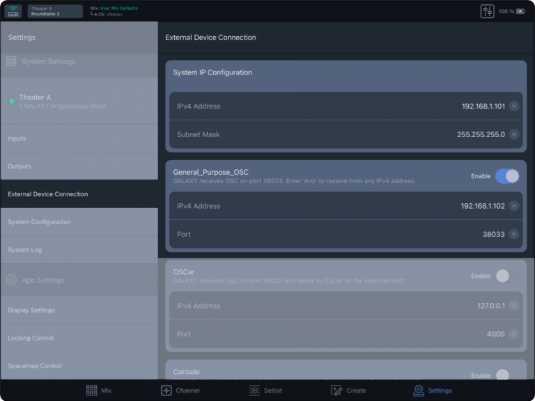
Settings, External Device Connection – System and General Purpose OSC IP Settings
Set the IPv4 address of the computer running QLab to be in the same IPv4 address range as the Spacemap Go system.
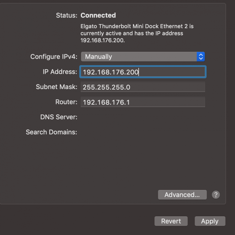
Setting IPv4 address of Apple computer
Note
If an IPv4 address was entered in the GENERAL PURPOSE OSC field, use that IPv4 address to set the QLab Alias IPv4 address (Spacemap Go targets this address).
Set the network settings in QLab: under NETWORK > NETWORK CUE DESTINATION PATCHES, select the Spacemap Go interface, type in the Spacemap Go system IP address and port number 38033.
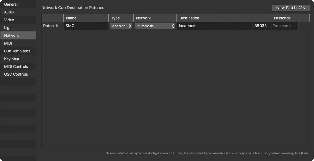
QLab Settings with GALAXY Hardware
Connection steps: Virtual GALAXY processor(s)
Virtual GALAXY processors running on the same computer as QLab
GENERAL PURPOSE OSC: toggle the ENABLE slider to ON. Use the default values for all other settings.
In QLab: NETWORK > NETWORK CUE DESTINATION PATCHES, select the Spacemap Go interface. Enter
localhostor127.0.0.1in the Destination Address field. Enter38033in the Port field.
QLab Network Settings
Virtual GALAXY processors NOT running on the same computer as QLab
The Spacemap Go SYSTEM IP ADDRESS is not necessary in this instance. The Virtual GALAXY will respond to the Compass computer IPv4 address.
GENERAL PURPOSE OSC > IPv4 ADDRESS: Enter the IPv4 address of the Compass computer.
GENERAL PURPOSE OSC > PORT: Leave the port set to default, (0). In the instance that an event in SMG needs to trigger a QLab event, set the port number to 53000 – the default Rx (receiving) port used by QLab.
GENERAL PURPOSE OSC: toggle the ENABLE slider to ON.
In QLab: NETWORK > NETWORK CUE DESTINATION PATCHES, select the Spacemap Go interface, enter the IPv4 address of the Compass computer running the Virtual Galaxy. Enter
38033in the port field.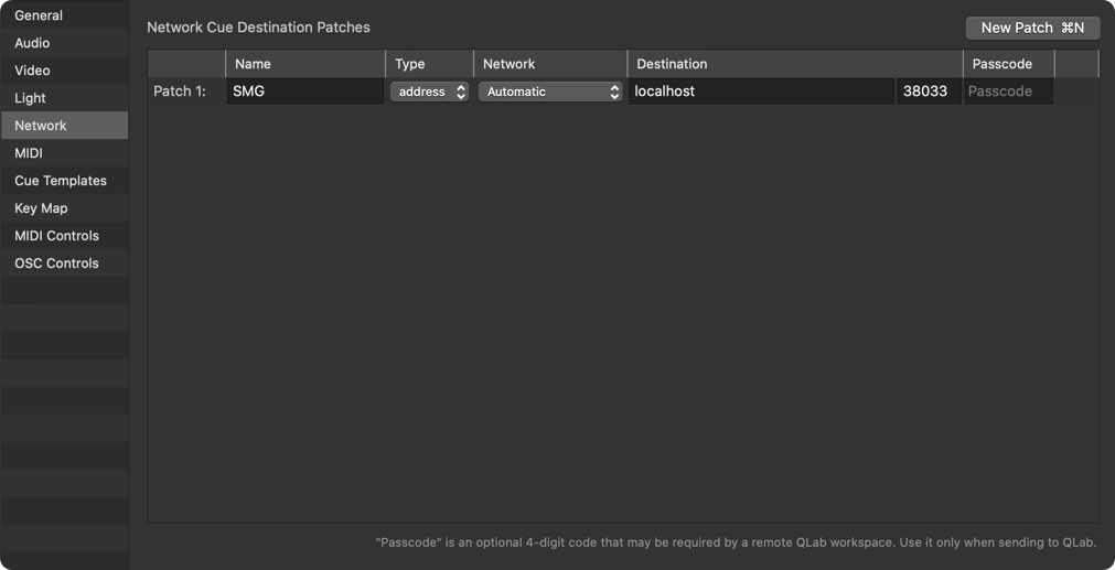
QLab Settings with GALAXY Hardware
Virtual GALAXY processors not running on the same computer as QLab
The Spacemap Go SYSTEM IP ADDRESS is not necessary in this instance. The Virtual GALAXY will respond to the Compass computer IPv4 address.
GENERAL PURPOSE OSC > IPv4 ADDRESS: Enter the IPv4 address of the Compass computer.
GENERAL PURPOSE OSC > PORT: Leave the port set to default (0). In the instance that an event in SMG needs to trigger a QLab event, set the port number to 53000 – the default Rx (receiving) port used by QLab.
GENERAL PURPOSE OSC: toggle the ENABLE slider to ON.
In QLab: NETWORK > NETWORK CUE DESTINATION PATCHES, select the Spacemap Go interface, and enter the IPv4 address of the Compass computer running the Virtual Galaxy. Enter 38033 in the port field.
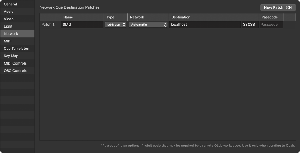
QLab Settings with GALAXY Hardware
Virtual GALAXY processors running on the same computer as QLab
GENERAL PURPOSE OSC: toggle the ENABLE slider to ON. Use the default values for all other settings.
In QLab: NETWORK > NETWORK CUE DESTINATION PATCHES, select the Spacemap Go interface. Enter
localhostor127.0.0.1in the Destination Address field. Enter38033in the Port field.
QLab Network Settings
General purpose OSC commands
The table below lists the general purpose OSC commands that a Spacemap Go system will respond to.
Command | String | Value | Example(s) |
|---|---|---|---|
Spacemap Go Channel | /channel | ||
X and Y Value of the Panner Position within a Spacemap | /channel/1-32/position (1st Argument is X, 2nd Argument is Y) | -1000 to 1000 | /channel/1/position 125 300 (X Position is 125, Y Position is 300) |
Control Channel Level | /channel/1-32/level | -90 to +10 -90 = -90 dB +10 = +10 dB | /channel/1/level 0 (Set Channel 1 Level to 0 dB) /channel/1/level -6 (Set Channel 1 Level to -6 dB) |
Control Channel Mute | /channel/1-32/mute | 0 = OFF 1 = ON | /channel/1/mute 0 (Unmute Channel 1) /channel/1/mute 1 (Mute Channel 1) |
Crossfade Value Between Two Spacemaps on a Channel | /channel/1-32/crossfade | -100 to 100 -100=Left Map 100% 100=Right Map 100% | /channel/1/crossfade -100 /channel/1/crossfade 0 /channel/1/crossfade 100 |
Control Channel Spread | /channel/1-32/spread | 0 to 100 0 = 0% 100 = 100% | /channel/1/spread 14 (Sets the Spread to 14%) NOTE: Spread is Logarithmic, 14% is Optimal for Most Cases |
Play Trajectory | /channel/1-32/trajectory/status | play | /channel/1/trajectory/status play |
Pause Trajectory | /channel/1-32/trajectory/status | pause | /channel/1/trajectory/status pause |
Stop and Restart Trajectory from Start Point | /channel/1-32/trajectory/status | stop | /channel/1/trajectory/status stop |
Control Mix Level | /mix/level | -90 to +10 -90 = -90 dB +10 = +10 dB | /mix/level 0 (Mix Level = 0 dB) /mix/level -6 (Mix Level = -6 dB) |
Control Mix Mute | /mix/mute | 0 = OFF 1 = ON | /mix/mute 0 (Unmute the Mix) /mix/mute 1 (Mute the Mix) |
Control System Trim Level | /system/level | -90 to +10 -90 = -90 dB +10 = +10 dB | /system/level 0 (System Trim Level = 0 dB) /system/level -6 (System Trim Level = -6 dB) |
Recall Channel Snapshot | /recall/channel | Use the External Recall ID Value Found for Each Snapshot to Recall | /recall/channel 3003 (Recalls the Channel Snapshot with the External Recall ID of 3003) |
Recall Mix Snapshot | /recall/mix | Use the External Recall ID Value Found for Each Snapshot to Recall | /recall/mix 2002 (Recalls the Mix Snapshot with the External Recall ID of 2002) |
Recall System Snapshot | /recall/system | Use the External Recall ID Value Found for Each Snapshot to Recall | /recall/system 1001 (Recalls the System Snapshot with the External Recall ID of 1001) |
Translating QLab regular expressions into channel range commands
Channel Range Values | QLab Regular Expression Values | Example Range Cues |
|---|---|---|
Channels 1-9 | [1-9] | /channel/[1-9]/position: #x# #y# |
Channels 10-19 | 1[0-9] | /channel/1[0-9]/position: #x# #y# |
Channels 20-29 | 2[0-9] | /channel/2[0-9]/position: #x# #y# |
Channels 10-19 | 1[0-9] | /channel/1[0-9]/position: #x# #y# |
Control using OSCar
To automate the Spacemap Panner coordinates, Spread percentage, and the Spacemap A/B Crossfade, the OSCar plugin from IRCAM is used with a Digital Audio Workstation (DAW). The Oscar plugin is available in the following formats: AU, VST3, AAX for macOS, and VST3 for Windows. OSCar requires a 64-bit DAW application.
Universal Setup Instructions
Note
The Spacemap System must be operational before attempting the following steps.
Set IPv4 addresses
Set the following IPv4 addresses to the same class C range (e.g., 192.168.1.x, where x is between 1 and 255):
The computer running the DAW,
The OSCar External Device Connection window,
The iPad running Spacemap Go,
IPv4 address of OSCar External Device Connection in Spacemap Go (Spacemap Go > SETTINGS VIEW > EXTERNAL DEVICE CONNECTION > OSCar). This step also sets the IPv4 address of the GALAXY processor(s).
Spacemap Go – enable OSCar
Enable OSCar within the Spacemap Go App (Spacemap Go > SETTINGS VIEW > EXTERNAL DEVICE CONNECTION > OSCar).
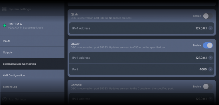
Spacemap Go – Settings View, External Device Connection, OSCar
Add a Spacemap to the desired channel.
Download the OSCar plugin.
Unzip the folder and find the user manual in the main directory (Windows) or in the Documents folder (MacOS).
Follow the instructions included with the download to install OSCar.
Navigate to /Ircam/oscar/oscar.xml:
macOS: /Users/username/Documents/Ircam/oscar/
Windows: C:\Users\username\Documents\Ircam\oscar\
Delete the default
oscar.xmlfile in the Ircam/oscar directory.Download the
.zipfile containing the Spacemap version of theoscar.xmlfile: oscar.zip.
Move the downloaded
.zipfile (oscar.zip) to theIrcam/oscardirectory.Decompress the Spacemap
oscar.zipfile and delete the.zipfile.Launch the DAW of your choice.
Initialize the OSCar Plugin.
Note
If the DAW does not initialize the Oscar Plugin, confirm it is allowed within the plugin manager.
Configure settings in OSCar:
Plugin ID # = SpaceMap Go Channel Number
Output IP = Spacemap Go OSCar External Device Connection IPv4 Address (default is 127.0.0.1; tap to edit), not the IP address of the iPad
Output Port = 38033
Input Port = 4000
To verify the IPv4 connection, click the ping button in the OSCar plugin; the green circle should blink.
Add an automation lane for a channel in the DAW and select a specific Spacemap control point:
Channel Position X
Channel Position Y
Channel Crossfade
Channel Spread
Add automation to the automation lane.
Note
An instance of the OSCar plugin can be added to any channel. Each instance of the OSCar plug-in controls one channel.
Playback of the automation should move the control point(s) of the Spacemap System and be displayed in Spacemap Go for the selected channel.
These control points are bidirectional, also allowing automation lane values to be written in the DAW by changing the controls of a channel in Spacemap Go.
Note
Frequently, the first time some DAWs try to load OSCar, a re-scan of the plug-ins is required. Each DAW behaves differently.

Logic Pro X – Plugin Manager, select Use and Reset & Rescan Selection
OSCar in Logic

Spacemap Go, Logic, OSCar – Bi-Directional Control
OSCar in Reaper
After the OSCar plugin is installed, open Reaper.
Select Insert a New Track from the Track menu.
On the channel, select the FX button to insert a plugin. In the pop-up, use the filter at the bottom to easily find the OSCar plugin. Select OSCar from the plugin list; click OK. When the FX window is opened, the OSCar plugin is listed.
If the plugin is not listed, select REAPER > PREFERENCES. In the left column, scroll to PLUG-INS > VST, and click the RE-SCAN button in the right panel.
Repeat steps 1 and 2 to add the plug-in to the desired channels.
Click the ENVELOPE button on a channel to make display selections for the envelopes under the waveform of the audio track – X Locator, Y Locator, Spacemap Crossfades, and Spread envelopes. Select the automation mode to write the values sent from Spacemap Go or the automation mode to read the envelope values and send them to Spacemap Go.
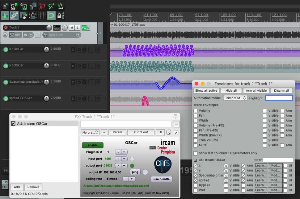
OSCar Plugin in Reaper
OSCar in Pro-Tools
In the OSCar folder is a video with instructions for using OSCar with Pro-Tools.
Spacemap Go frequently asked questions (FAQ)
The state of Channel Recall Safe is not stored when saving Channel or Mix Snapshots. The Recall Safe state is not stored when a Project is saved.
If the iPad is running iOS 15 or later, it may be the Privacy Settings of the iPad. See System Requirements.
The two GALAXY Ethernet NICs can each have up to three IPv4 addresses assigned to them. The GALAXY <-> Compass communication will either have a static or a DHCP assigned IPv4 addresses which are viewed in Compass software (IPv4 address #1 for each GALAXY Ethernet NIC).
The Spacemap System doesn’t use IPv4 addresses by default, but if a user enters an IPv4 address for a Spacemap System in the SETTINGS > EXTERNAL DEVICE CONNECTION tab:
Each GALAXY is assigned another IPv4 address for each Ethernet NIC (IPv4 address #2 for each GALAXY Ethernet NIC).
The “Master” GALAXY Ethernet NICs are also assigned the System IPv4 Address set in the app’s SETTINGS > EXTERNAL DEVICE CONNECTION tab (IPv4 address #3 for each of the “Master” GALAXY Ethernet NICs).
Note
The “Master” GALAXY controls the system-level communication with Spacemap Go and coordinates the communication with other devices that are part of the Spacemap Go System.
Yes, and: the IPv4 addresses listed in Compass software are used for GALAXY <-> Compass communication. This communication is usually via IPv6. GALAXY processors maintain IPv4 addresses as a fallback option in case a network does not support IPv6 addressing or to receive external commands from devices using IPv4 when a GALAXY is in Normal mode. If there is a DHCP server present on the network, the GALAXY will request an IPv4 address.
Spacemap Go uses IPv6 by default until there is a System IPv4 Address entered in the SETTINGS > EXTERNAL DEVICE CONNECTION tab. An IPv4 address is added to the “Master” GALAXY and each additional GALAXY processor.
The IPv4 addresses for GALAXY <-> Compass communication, and the IPv4 addresses for GALAXY <-> Spacemap Go communication reside on the same GALAXY Ethernet NIC at all times.
Note
The “Master” GALAXY controls the system-level communication with Spacemap Go and coordinates the communication with other devices that are part of the Spacemap Go System.
By default, the Spacemap Go system uses IPv6 addresses for connection between GALAXY processors and iPads. IPv4 addresses can be enabled for networks that will not allow IPv6 traffic or for external control from devices that only use IPv4 address.
IPv6 addressing is used when a Spacemap Go system is initially configured. After configuration, an IPv4 address for a Spacemap System can be entered in the app’s SETTINGS > EXTERNAL DEVICE CONNECTION tab, enabling IPv4 communication. By default, this field is empty, and the system will not request an IPv4 address from DHCP server.
For additional information, see FAQ: Is the IPv4 address shown in Compass the IPv4 address of the GALAXY processor?
When a Galileo GALAXY is in Spacemap Mode, the AVB controller embedded in the GALAXY processor controls the AVB input assignments of all the GALAXY processors that have the same AVB Group Name on the same network. This includes any GALAXY processors operating in Normal mode. All AVB connections established when a GALAXY processor is in Normal mode will be overwritten when it is re-started in Spacemap Mode and the Spacemap Go System is configured with the Spacemap Go app.
To manually control the AVB input connections of a GALAXY processor using the Compass software or other AVB controller software, change the AVB Group Name of the GALAXY processor to one that does not include any GALAXY processors in Spacemap Mode.
For Spacemap Go systems that have more than one GALAXY processor, Milan AVB signal connections are necessary to share the inputs across multiple processors, requiring an AVB Avnu certified network switch. When using three or more processors, the network connection speed needs to be 1000baseT (1Gb/sec), enough bandwidth to transmit multiple AVB streams, up to 28 96k/32-bit streams. When using two processors, 100bT speed provides enough bandwidth for the transport of shared inputs via Milan AVB between the processors.
If a network cable is damaged, the link may be non-operational or the speed may drop to 100baseT, without notification in the software.
When some laptop computers are in sleep mode, the network connection speed is reduced to 100baseT.
The output processing settings of a GALAXY processor can be stored from both Compass software and the Spacemap Go App. When a GALAXY processor reboots in Spacemap Mode, the processor will not recall a Snapshot identified as Boot, but will instead load the System Snapshot and User Default Mix Snapshot, see Configure GALAXY processors and Quick Start Step 3 (optional): Keep GALAXY settings when using an in-use processor sections.
Your data is not lost if you saved a GALAXY Snapshot during system tuning. To save the processor settings with the Spacemap Project:
Launch Spacemap Go on an iPad and Compass software on a computer.
In Compass, recall the proper GALAXY Snapshot.
In Spacemap Go, update the System Snapshot, and save a new Spacemap Project.
If the GALAXY processors are in Spacemap Mode and the network connections are correctly made, restart/power cycle the iPad.
Nothing is wrong. When testing a Spacemap in Create View, audio is not sent to the outputs intentionally. Observe the matrix values (top of view – swipe to view additional matrix outputs) to verify the Spacemap is performing the panning functions desired.
To save the configuration to the GALAXY memory, tap the Project Settings button to open Project Settings. Tap SAVE PROJECT and select SAVE TO GALAXY. When saved and the LOAD PROJECT FROM GALAXY ON RESTART (Project Settings, System Configuration) is selected, the Project will be recalled upon power cycle.
Most likely, Trisets need to be added. In Create View, Create New Spacemap, tap Triset icon , tap ADD to manually select three nodes or tap the Autobuild Trisets OPEN button (lower-left), then tap BUILD TRISETS to build Trisets automatically.
General purpose OSC commands
The table below lists the general purpose OSC commands that a Spacemap Go system will respond to.
Command | String | Value | Example(s) |
|---|---|---|---|
Spacemap Go Channel | /channel | ||
X and Y Value of the Panner Position within a Spacemap | /channel/1-32/position (1st Argument is X, 2nd Argument is Y) | -1000 to 1000 | /channel/1/position 125 300 (X Position is 125, Y Position is 300) |
Control Channel Level | /channel/1-32/level | -90 to +10 -90 = -90 dB +10 = +10 dB | /channel/1/level 0 (Set Channel 1 Level to 0 dB) /channel/1/level -6 (Set Channel 1 Level to -6 dB) |
Control Channel Mute | /channel/1-32/mute | 0 = OFF 1 = ON | /channel/1/mute 0 (Unmute Channel 1) /channel/1/mute 1 (Mute Channel 1) |
Crossfade Value Between Two Spacemaps on a Channel | /channel/1-32/crossfade | -100 to 100 -100=Left Map 100% 100=Right Map 100% | /channel/1/crossfade -100 /channel/1/crossfade 0 /channel/1/crossfade 100 |
Control Channel Spread | /channel/1-32/spread | 0 to 100 0 = 0% 100 = 100% | /channel/1/spread 14 (Sets the Spread to 14%) NOTE: Spread is Logarithmic, 14% is Optimal for Most Cases |
Play Trajectory | /channel/1-32/trajectory/status | play | /channel/1/trajectory/status play |
Pause Trajectory | /channel/1-32/trajectory/status | pause | /channel/1/trajectory/status pause |
Stop and Restart Trajectory from Start Point | /channel/1-32/trajectory/status | stop | /channel/1/trajectory/status stop |
Control Mix Level | /mix/level | -90 to +10 -90 = -90 dB +10 = +10 dB | /mix/level 0 (Mix Level = 0 dB) /mix/level -6 (Mix Level = -6 dB) |
Control Mix Mute | /mix/mute | 0 = OFF 1 = ON | /mix/mute 0 (Unmute the Mix) /mix/mute 1 (Mute the Mix) |
Control System Trim Level | /system/level | -90 to +10 -90 = -90 dB +10 = +10 dB | /system/level 0 (System Trim Level = 0 dB) /system/level -6 (System Trim Level = -6 dB) |
Recall Channel Snapshot | /recall/channel | Use the External Recall ID Value Found for Each Snapshot to Recall | /recall/channel 3003 (Recalls the Channel Snapshot with the External Recall ID of 3003) |
Recall Mix Snapshot | /recall/mix | Use the External Recall ID Value Found for Each Snapshot to Recall | /recall/mix 2002 (Recalls the Mix Snapshot with the External Recall ID of 2002) |
Recall System Snapshot | /recall/system | Use the External Recall ID Value Found for Each Snapshot to Recall | /recall/system 1001 (Recalls the System Snapshot with the External Recall ID of 1001) |

