Operating Instructions — USW-210P
Subwoofer



The USW-210P compact narrow subwoofer provides robust, extended low-frequency response for installed sound applications that require convincing bass impact from a slender, low-profile loudspeaker. Its dual-driver configuration permits a narrow form factor that fits into restricted architectural spaces to produce output levels equal to or exceeding systems with single 12-inch (or larger) drivers. Its slanted connector panel enables flush-mounting the cabinet against wall surfaces, reducing required installation depth to 12 inches (30.5 cm), including connectors.
The USW-210P subwoofer is ideal for installations requiring high performance and versatility along with an appealing, discreet aesthetic appearance. The USW-210P integrates easily with other Meyer Sound loudspeaker systems, such as CAL™ and ULTRA Series loudspeakers.
The USW-210P has an operating frequency range of 30–140 Hz with a linear peak SPL of 126 dB (measured in half-space at 4 m and referred to 1m using M-noise). The long skinny bass reflex cabinet employs the same port design as Meyer Sound’s flagship 1100-LFC low-frequency control element for high efficiency and low port distortion.
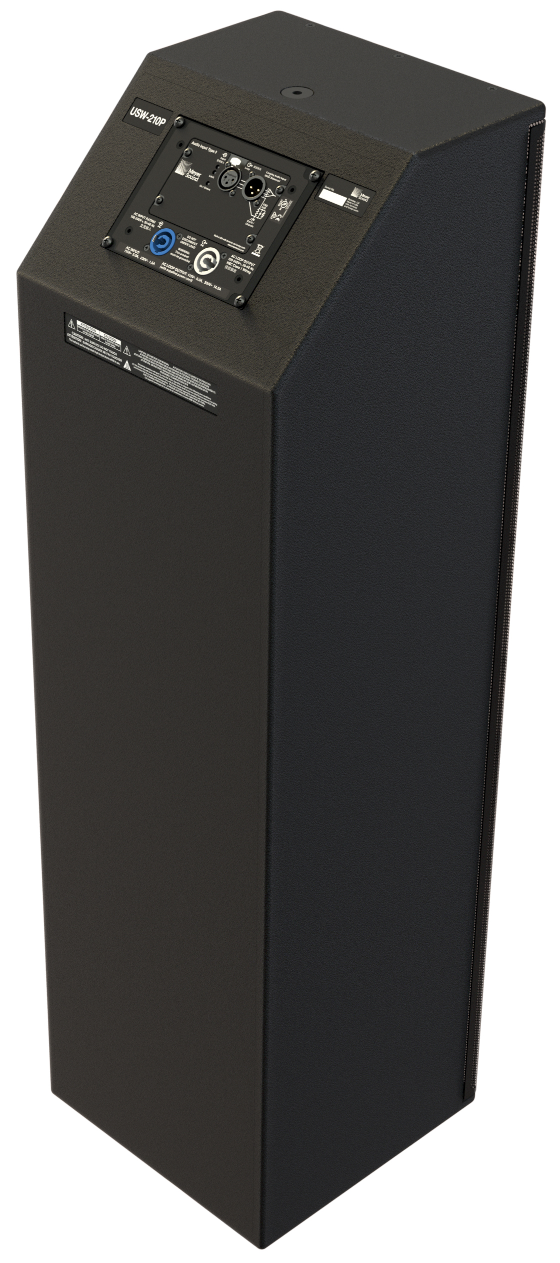
USW-210P Slanted Connector Panel
Integrated Amplifier and Processing
A self-powered loudspeaker, the USW-210P cabinet houses a two-channel Class D power amplifier. The audio signal is processed with correction filters for flat frequency and phase responses, and by driver protection circuitry. The amplifier/processing package incorporates Meyer Sound’s Intelligent AC which auto-selects the correct operating voltage, suppresses high voltage transients, filters EMI and provides soft-start power-up. The USW-210P cabinet provides audio XLR and powerCON 20 input and looping output connectors.
An optional RMS™ remote monitoring system module provides comprehensive monitoring of loudspeaker parameters from a host computer running Compass Control Software.
The USW-210P loudspeaker’s on-board amplifier is convection cooled.
Integrated Rigging Points
Meyer Sound constructs the USW-210P cabinet from premium multi-ply birch coated with a slightly textured black finish and includes a stamped-steel grille to protect the drivers. Weather protection and custom color finishes for specific cosmetic requirements are available options.
With its versatile shape, the USW-210P can be placed on the ground in a horizontal or vertical position to accommodate installation requirements.
The USW-210P comes standard with M8 mounting points at the top and bottom for use with the optional U-bracket that facilitates wall or ceiling mounting.
In addition, an optional aluminum base plate is available to enhance stability when placing the USW-210P free-standing vertically. This base plate can attach to either end of the loudspeaker, so that the connectors can be oriented at either the top or the bottom when it is free-standing.
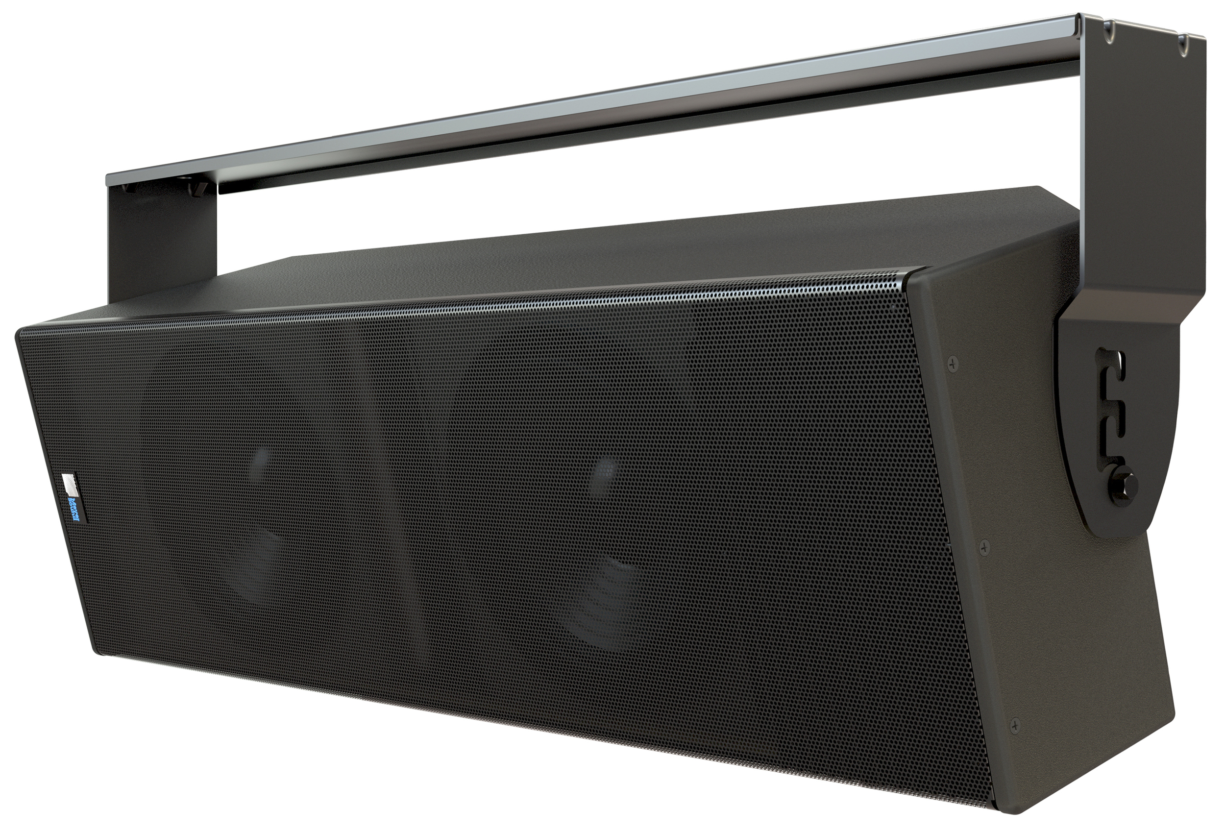
USW-210P with MUB-USW-210P (ceiling mount)
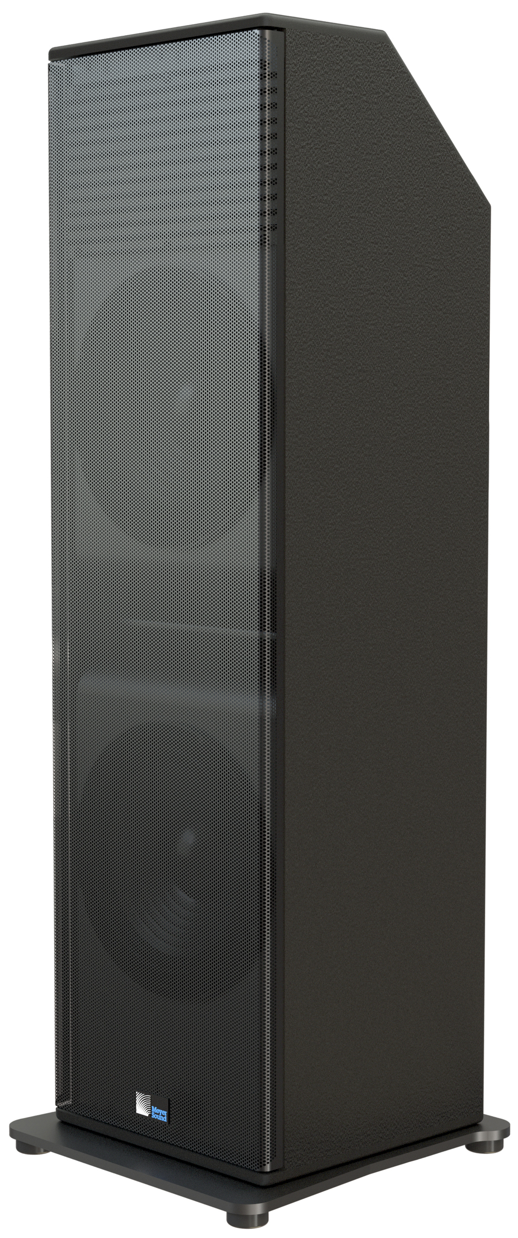
USW-210P in MBP-USW-210P Base Plate
The USW-210P subwoofer combines advanced loudspeaker technology with equally advanced power capabilities. Understanding power distribution, voltage and current requirements, and electrical safety guidelines is critical for the safe operation of the device.
Power Requirements
AC Power Distribution
All components in an audio system (self-powered loudspeakers, mixing consoles, and processors) must be properly connected to an AC power distribution system, ensuring that AC line polarity is preserved and that all grounding points are connected to a single node or common point using the same cable gauge (or larger) as the neutral and line cables.
Caution
Make sure the voltage received by the USW-210P loudspeaker remains within its 90–264 V AC operating range. In addition, the ground line must always be used for safety reasons and the line-to-ground voltage should never exceed 250 V AC (typically 120 V AC from line to ground).
Before applying AC power to any Meyer Sound self-powered loudspeaker, make sure that the voltage potential difference between the neutral and earth-ground lines is less than 5 V AC when using single-phase AC wiring.
Note
Improper grounding of connections between loudspeakers and the rest of the audio system may produce noise or hum, or cause serious damage to the input and output stages of the system’s electronic components.
AC Connectors
The USW-210P user panel includes two powerCON 20 connectors, one for AC Input (blue) and one for AC Loop Output (gray), as shown in the figure below.
AC Input (Left) and AC Loop Output (Right) Connectors
AC Input (Blue)
The blue AC Input connector supplies power to USW-210P. The 3-conductor powerCON 20 is rated at 20 A and uses a locking connector that prevents accidental disconnections. A 10-foot AC power cable, rated at 15 A, is included with each loudspeaker. If the included AC power cable is replaced, make sure to use a cable with the appropriate power plug (on the other end) for the region where the unit will be operated. USW-210P requires a grounded outlet. To operate safely and effectively, it is extremely important that the entire system be properly grounded.
The AC Input connector also supplies power to any additional loudspeakers connected to the loudspeaker’s gray Loop Output connector.
Caution
When looping AC power for loudspeakers, do not exceed the current capability of the AC Input connector (20 A) or the included AC power cable (15 A). Consider the total current draw for all loudspeakers on the circuit, including the first loudspeaker.
AC Loop Output (Gray)
The gray AC Loop Output connector allows multiple
USW-210P to be looped and powered from a single power source. The 3-conductor powerCON 20 is rated at 20 A and uses a locking connector that prevents accidental disconnections. For applications that require multiple
USW-210P, connect the AC Loop Output of the first loudspeaker to the AC Input of the second loudspeaker and so forth.
The maximum number of loudspeakers that can be looped from the AC Loop Output connector is determined by the voltage of the power source, the current draw of the looped loudspeakers, the circuit breaker rating, and the rating of the AC power cable connected to the first USW-210P loudspeaker, as shown in the table below.
Circuit Breaker/ Connector Rating | 115 V AC | 230 V AC | 100 V AC |
|---|---|---|---|
15 A | 9 looped (10 total) | 18 looped (19 total) | 8 looped (9 total) |
20 A | 13 looped (14 total) | 24 looped (25 total) | 11 looped (12 total) |
Note
Current draw for USW-210P is dynamic and fluctuates as operating levels change. The indicated number of loudspeakers that can be looped assumes that operating levels are normal and not such that loudspeakers are constantly limiting.
USW-210P ships with a gray powerCON 20 cable mount connector, rated at 20 A, for assembling AC looping cables. Assembled 1-meter AC looping cables (PN 28.115.032.03) are also available from Meyer Sound.
Wiring AC Power Cables
USW-210P ships with a gray powerCON 20 cable mount connector, rated at 20 A, for assembling AC looping cables, as shown in the figure below. The pins on the powerCON 20 cable mount connector are labeled as follows:
L (Line)
N (Neutral)
PE (Protective Earth or Ground)
powerCON20Cable Mount Connector
How AC power cables are wired is determined by the type of AC power distribution system used (see AC Power Distribution). When wiring AC power cables for single-line systems, use one of the wiring schemes shown in the figure below, and described in the table below:
AC Wiring Scheme
Wire Color | Attach to the Following Terminal | |
|---|---|---|
U.S. / Canada 60 Hz | European 50 Hz | |
Black | Brown | Hot or live (L) |
White | Blue | Neutral (N) |
Green | Green and Yellow | Protective earth / ground (E or PE) |
Caution
When wiring AC power cables and distribution systems, it is important to preserve AC line polarity and connect the earth ground at both ends of the cable. USW-210P requires a grounded connection. Always use a grounded outlet and plug. It is extremely important that the system be properly grounded to operate safely and properly. Do not ground-lift the AC cable.
Voltage Requirements
USW-210P operates as intended when receiving AC voltage within the following range:
90–264 V AC, 50–60 Hz
If the voltage drops below 90 V, the loudspeaker uses stored power to continue operating temporarily; the loudspeaker powers off if the voltage does not return to its operating range.
If the voltage rises above 275 V, the power supply could become damaged.
Caution
The power source for USW-210P should always operate within the required operating range, at least a few volts from the upper and lower limits. This approach ensures that AC voltage variations from the service entry—or peak voltage drops due to cable runs—will not cause the loudspeaker’s amplifier to cycle on and off or cause damage to the power supply.
Current Requirements
Current draw for loudspeakers is dynamic and fluctuates as operating levels change. Because different cables and circuit breakers heat up at varying rates, it is important to understand the following types of current ratings and how they affect circuit breaker and cable specifications.
Idle Current — The maximum rms current during idle periods.
Maximum Long-Term Continuous Current — The maximum rms current during a period of at least 10 seconds. The maximum long-term continuous current is used to calculate temperature increases for cables and to ensure that the size and gauge of each cable conforms to electrical code standards. This current rating is also used to select appropriately rated, slow- reacting thermal breakers, which are recommended for loudspeaker power distribution. In addition, the maximum long-term continuous current can be used to calculate the AC looping capability for USW-210P loudspeakers.
Burst Current — The maximum rms current during a period of around 1 second. The burst current is used as a rating for magnetic breakers. It is also used for calculating the peak voltage drop in long AC cable runs according to the following formula:
V pk (drop) = I pk x R (cable total)
Maximum Instantaneous Peak Current — A rating for fast-reacting magnetic breakers.
Use the information in the table below to select the appropriate cable gauge and circuit breaker ratings for the system’s operating voltage.
Current Draw | 115 V AC | 230 V AC | 100 V AC |
|---|---|---|---|
Idle | 0.27 A rms | 0.25 A rms | 0.29 A rms |
Maximum Long-Term Continuous | 1.4 A rms | 0.7 A rms | 1.6 A rms |
Burst | 4.5 A rms | 2.1 A rms | 4.8 A rms |
Maximum Instantaneous Peak | 9.7 A rms | 4.6 A rms | 10.8 A rms |
The minimum electrical service amperage required by a loudspeaker system is the sum of the maximum long-term continuous current for all loudspeakers. An additional 30 percent above the combined Maximum Long-Term Continuous amperages is recommended to prevent peak voltage drops at the service entry.
Note
For best performance, the AC cable voltage drop should not exceed 10 V (10 percent at 115 V and 5 percent at 230 V). This approach ensures that the AC voltage variations from the service entry—or peak voltage drops due to longer cable runs—do not cause the amplifier to cycle on and off.
Intelligent AC Power Supply
USW-210P’s Intelligent AC™ power supply automatically selects the correct operating voltage (allowing the loudspeaker to be used internationally without manually setting voltage switches), eliminates high inrush currents with soft-start power up, suppresses high-voltage transients up to several kilovolts, filters common mode and differential mode radio frequencies (EMI), and sustains operation temporarily during low-voltage periods.
Powering on USW-210P
When powering on USW-210P, the following startup events take place over several seconds.
Audio output is muted.
Voltage is detected and the power supply mode is auto- matically adjusted as necessary.
The power supply ramps up.
On the user panel, the On/Status LED flashes multiple colors successively.
The On/Status LED turns solid green, indicating the loudspeaker is unmuted and ready to output audio.
Caution
If the On/Status LED does not turn solid green, or the USW-210P does not output audio after 10 seconds, remove AC power immediately and verify that the voltage is within the required range. If the problem persists, contact Meyer Sound Technical Support.
Electrical Safety Guidelines
Make sure to observe the following important electrical and safety guidelines.
The powerCON 20 connector should not be engaged or disengaged when under load or energized. Either de-energize or disconnect the other end of the cable.
USW-210P requires a grounded outlet. Always use a grounded outlet and plug.
Do not use a ground-lifting adapter or cut the AC cable ground pin.
Do not exceed the current capability of the 20 A AC Input connector for the loudspeaker. When looping loudspeakers, consider the total current draw for all loudspeakers on the circuit, including the first loudspeaker.
Make sure the AC power cable for the loudspeaker has the appropriate power plug (on the other end) for the area in which you will operate the loudspeaker. In addition, the AC power cable must be rated for the total current draw of all loudspeakers looped from the power source.
Do not operate the unit if the power cable is frayed or broken.
Keep all liquids away from USW-210P loudspeakers to avoid hazards from electrical shock.
Amplification and Audio Connectors
The USW-210P drivers are powered by a proprietary
2-channel, open-loop, class D amplifier. The audio signal is processed with correction filters for flat phase and frequency responses, and by driver protection circuitry.
Each channel has peak and rms limiters that prevent driver over-excursion and regulate voice coil temperatures.
The USW-210P user panel, shown in the figure below, includes Input and Loop output connectors for audio, Limit and On/Status LEDs, and RMS connectors and controls (see RMS Remote Monitoring System).
USW-210P User Panel (Shown with Optional RMS Module)
Audio Connectors
USW-210P is available with XLR 3-pin connectors for audio Input and audio Loop output, as shown in the figure below.
XLR 3-Pin Audio Connectors, Input and Loop Output
Audio Input (XLR 3-Pin Female)
The XLR 3-pin female Input connector accepts balanced audio signals with an input impedance of 10 kΩ. The connector uses the following wiring scheme:
Pin 1 — 1 kΩ to chassis and earth ground (ESD clamped)
Pin 2 — Signal (+)
Pin 3 — Signal (–)
Pins 2 and 3 carry the input as a differential signal. Pin 1 is connected to earth through a 1 kΩ, 1000 pF, 15 V clamped network. This circuitry provides virtual ground lift for audio frequencies while allowing unwanted signals to bleed to ground. Make sure to use balanced XLR audio cables with pins 1–3 connected on both ends. Telescopic grounding is not recommended and shorting an input connector pin to the case may cause a ground loop, resulting in hum.
Tip
If the loudspeaker produces unwanted noise or hiss, disconnect its input cable. If the noise stops, there is most likely nothing wrong with the loudspeaker. To locate the source of the noise, check the source audio, AC power, and electrical ground.
Audio Loop Output (XLR 3-Pin Male)
The XLR 3-pin male Loop output connector allows multiple loudspeakers to be looped from a single audio source. The Loop output connector uses the same wiring scheme as the Input connector. For applications that require multiple USW-210P, connect the Loop output of the first loudspeaker to the Input of the second loudspeaker and so forth.
Note
The Loop output connector is wired in parallel to the Input connector and transmits the unbuffered source signal even when the loudspeaker is powered off.
Calculating Load Impedance for Looped Audio Signals
To avoid distortion when looping multiple loudspeakers, make sure the source device can drive the total load impedance of the looped loudspeakers. In addition, the source device must be capable of delivering approximately 20 dBV (10 V rms into 600 Ω) to yield the maximum SPL over the operating bandwidth of the loudspeakers.
To calculate the load impedance for the looped loudspeakers, divide 10 kΩ (the input impedance for a single loudspeaker) by the number of looped loudspeakers. For example, the load impedance for 10 USW-210P is 1000 Ω (10 kΩ/ 10). To drive this number of looped loudspeakers, the source device should have an output impedance of 100 Ω or less. This same rule applies when looping USW-210P with other Meyer Sound self-powered loudspeakers.
Note
Most source devices are capable of driving loads no less than 10 times their output impedance.
Tip
Audio outputs from Meyer Sound’s loud- speaker GALAXY Network Platform have an output impedance of 50 ohms. Each output can drive up to 20 Meyer Sound (10 kΩ) loudspeakers without distortion.
Caution
Make sure that all cabling for looped loudspeakers is wired correctly (Pin 1 to Pin 1, Pin 2 to Pin 2, and so forth) to prevent the polarity from being reversed. If one or more loudspeakers in a system have reversed polarity, frequency response and coverage will be significantly degraded.
TruPower Limiting
The USW-210P employs Meyer Sound’s advanced TruPower® limiting. Conventional limiters assume a constant driver impedance and set the limiting threshold by measuring voltage alone. This method is inaccurate, because driver impedances change as frequency content in the source material changes, and as thermal values for the loudspeaker’s voice coil and magnet vary. Consequently, conventional limiters often begin limiting prematurely, which reduces system headroom and dynamic range.
In contrast, TruPower limiting anticipates varying driver impedances by measuring both current and voltage to compute the actual power dissipation in the voice coil. This approach improves performance, both before and during limiting, by allowing the driver to produce the maximum SPL across its entire frequency range, while also retaining signal peaks. TruPower limiting also eliminates power compression at high levels over lengthy periods, which helps regulate voice coil temperatures, thereby extending the life of the driver.
LF Limit LEDs
The low-frequency drivers for USW-210P are powered by separate amplifier channels, each with their own limiter. Limiting activity is indicated with two Limit LEDs on the user panel.
USW-210P Limit LEDs
When engaged, the limiters not only protect the drivers but also prevent signal peaks from causing excessive distortion in the amplifier channels, thereby preserving headroom and maintaining smooth frequency response at high levels.
When levels return to normal, below the limiter thresholds, limiting ceases.
USW-210P performs within its acoustical specifications at normal temperatures when the Limit LEDs are unlit, or when the LEDs are lit for 2 seconds or less and then turn off for at least 1 second. If the LEDs remain lit for longer than
3 seconds, the loudspeaker enters hard limiting where:
Increases to the input level have no effect
Distortion increases due to clipping
Drivers are subjected to excessive heat and excursion, thereby compromising their lifespan
Caution
The Limit LEDs indicate when a safe, optimum level is exceeded. If an USW-210P loudspeaker system begins to limit before reaching the desired SPL, consider adding more units to the system.
AMPLIFIER COOLING SYSTEM
The USW-210P loudspeaker is convection cooled. The amplifier’s heat sink provides natural convection cooling from the air flowing near its fins.
Caution
The USW-210P heat sink can reach very high temperatures during extreme operation. Wait 15 minutes for the unit to cool before touching.
CHAPTER 3: AMPLIFICATION AND AUDIO CONNECTORS
ON/STATUS LED
During normal operation, when USW-210P is powered on, the On/Status LED is solid green. If the loudspeaker encounters a hardware fault, or the unit begins to overheat, the LED flashes red. In some instances, the loudspeaker will continue to output audio while the LED flashes red, though with a reduction in the limiter threshold and acoustic output to protect the loudspeaker.
If a loudspeaker is overheating (for RMS-equipped loudspeakers, you can verify this situation in Compass RMS), a reduction in SPL may be necessary. If after a reduction in SPL and an appropriate cooling period the On/Status LED continues to flash red (does not return to solid green), contact Meyer Sound Technical Support.
If the On/Status LED flashes red and the loudspeaker does not output audio, contact Meyer Sound Technical Support immediately.
CAUTION: If an USW-210P loudspeaker system consistently overheats before reaching the
desired SPL, consider adding more units to the system.
NOTE: During startup, the On/Status LED flashes multiple colors successively. For more
information about the power on sequence, see “Intelligent AC Power Supply” on page 14.
TIP: When an USW-210P is connected to an RMS network, the Compass RMS software provides
additional feedback about the loudspeaker’s hardware status and operating temperature. For more informa- tion, see Chapter 5, “RMS Remote Monitoring System.”
CHAPTER 4: RIGGING
With its versatile shape, the USW-210P can be placed on the ground in a horizontal or vertical position to accommodate installation requirements. The USW-210P comes standard with M8 mounting points at the top and bottom for use with the optional U-bracket that enables wall or ceiling mounting.
In addition, an optional aluminum base plate is available to enhance stability when placing the USW-210P free-standing vertically (connectors at top or bottom). Optional rigging details are provided in Table 4
Amplifier Cooling System
On / Status LED
Rigging
Important Safety Considerations
When installing Meyer Sound loudspeakers, the following precautions should always be observed:
All Meyer Sound products must be used in accordance with local, state, federal, and industry regulations. It is the owner’s and user’s responsibility to evaluate the
Table 4: USW-210P Rigging Kit Options
reliability of any rigging method for their application. Rigging should only be carried out by experienced professionals.
Use mounting and rigging hardware that has been rated to meet or exceed the weight being hung.
Make sure to attach mounting hardware to the building's structural components (studs or joists), and not just to the wall surface. Verify that the building's structure and the anchors used for the installation will safely support the total weight of the mounted loudspeakers.
Use mounting hardware appropriate for the surface where the loudspeaker will be installed.
Make sure bolts and eye bolts are tightened securely. Meyer Sound recommends using Loctite® on eye bolt threads and safety cables.
Inspect mounting and rigging hardware regularly. Immediately replace any worn or damaged components.
Model | Features |
|---|---|
MBP-USW-210P Base Plate (PN 40.010.970.01) | Aluminum base plate enhances stability when placing the USW-210P free-standing vertically (it connects to top or bottom). The kit includes an M8 screw to attach the base plate to the loud- speaker. |
MUB-USW-210P U-Bracket (PN 40.277.969.01) | The MUB-USW-210P U-Bracket allows a single USW-210P loudspeaker to be mounted to a wall (in either vertical or horizontal orientations), to the ceiling or onto the floor. The kit includes two M8 screws to attach the MUB-USW-210P to the loudspeaker. |
THE MBP-USW-210P BASE PLATE
The MUB-USW-210P Base Plate (PN 40.010.970.01)
enhances stability when placing the USW-210P
free-standing vertically (connects to top or bottom). This kit includes the aluminum base plate and an M8 screw to attach the base plate to the loudspeaker. The base plate may be mounted on either end of the speaker to provide flexibility in accessing the user panel. For specifications, see “MBP-USW-210P Dimensions” on page 41.
MBP-USW-210P Base Plate
NOTE: The base plate has an M20 thread and can be used as a base plate with a short M20 pole for small speakers, such as
Meyer Sound’s MM-4XP or UP-4slim loudspeakers.
The base plate attaches to the subwoofer using the M8 center bolt as the main attachment point. One of the grille frame screws is also used to increase stability and to avoid rotation of the loudspeaker on the plate.
To attach the plate, first remove the center grille screw. Then insert the M8 bolt through the base plate and reinsert the grille screw (Figure 14).
Base Plate Attachment to Loudspeaker, Exploded View
MBP-USW-210P Base Plate, User Panel Oriented on Top
MBP-USW-210P Base Plate, User Panel oriented on Bottom
CHAPTER 4: RIGGING
THE MUB-USW-210P U-BRACKET
The MUB-USW-210P U-Bracket (Figure 17) (40.277.969.01) allows a single USW-210P loudspeaker to be mounted to a wall in either vertical or horizontal orientations (Figure 18 and Figure 19), to the ceiling
(Figure 20) or onto the floor. The MUB-USW-210P has three positions for attachment to provide flexibility in mounting. The kit includes two M8 screws for attaching the
MUB-USW-210P to the loudspeaker. For specifications, reference “MUB-USW-210P Dimensions” on page 39 and “USW-210P with MUB-USW-210P Dimensions” on
MUB-USW-210P U-Bracket
MUB-USW-210P Wall Mount, Horizontal
MUB-USW-210P Wall Mount, Vertical
MUB-USW-210P Ceiling Mount
The USW-210P loudspeaker optionally includes an RMS remote monitoring system module, allowing it to be connected to an RMS network. RMS reports, in real time, the status and power usage of multiple Meyer Sound loudspeakers from a Mac or Windows-based computer. The RMServer communicates with Meyer Sound loudspeakers equipped with RMS modules. RMServer is a compact, Ethernet-based hardware unit with two FT-10 RMS data ports. RMServer stores system configurations internally, eliminating most manual data entry. Systems can be monitored from a computer at front-of-house or backstage, or from a laptop anywhere within the venue over WiFi.
NOTE: For the latest RMS system requirements, visit meyersound.com).
NOTE: RMS does not control AC power