Operating Instructions — TIGRA
Line Array



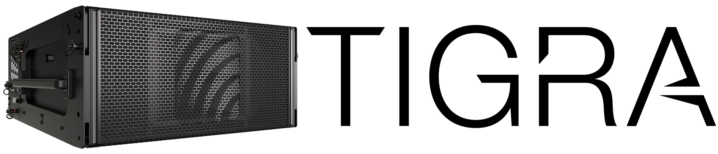
The self-powered TIGRA™ linear array loudspeaker delivers full-scale impact in applications where space, weight, and sightlines matter, with the authority of a major touring system in a compact cabinet.
There are two TIGRA loudspeaker models with different horizontal dispersions:
TIGRA-L: 85 degrees
TIGRA-W: 110 degrees
TIGRA loudspeakers carry forward the Native Mode concept; they are ready to be deployed without the need for equalization, tuning, or presets. By delivering the same signal to all array elements, whether by looping analog signals or assigning each loudspeaker the same Milan AVB signal, the array's response will match or closely resemble user expectations. Larger and smaller arrays will have a little more or less low-mid response, which is easily modified by engaging the on-board Tru-Shaping filters.
A high-output switch-mode power supply reduces weight and improves efficiency, operating at 100–240 V AC, 50–60 Hz.
Each loudspeaker ships with a 9-foot (3 m) power cable terminated with a female NAC3F-TRUE1-S powerCON connector at one end and a regionally appropriate wall socket connector at the other end, or a power connector-only option in addition to an unterminated cable-mount CAT 5E NE8MX-B-TOP network connector and an unterminated cable-mount 3-pin XLR NX3MX-TOP analog audio connector.
Integrated Galileo GALAXY processing in Type 3P GEN-1 input modules reduces or eliminates upstream processing. The Milan AVB digital audio input enables direct connection from a Milan AVB-enabled console to TIGRA loudspeakers, reducing hardware, cabling, and processor racks.
The user panel provides analog audio, Milan AVB network, and AC power connections using Neutrik True Outdoor Protection (TOP) connector systems. IP65 ingress protection is maintained only when compatible Neutrik TOP cable connectors are used or when the sealing caps are properly seated on unused connectors.
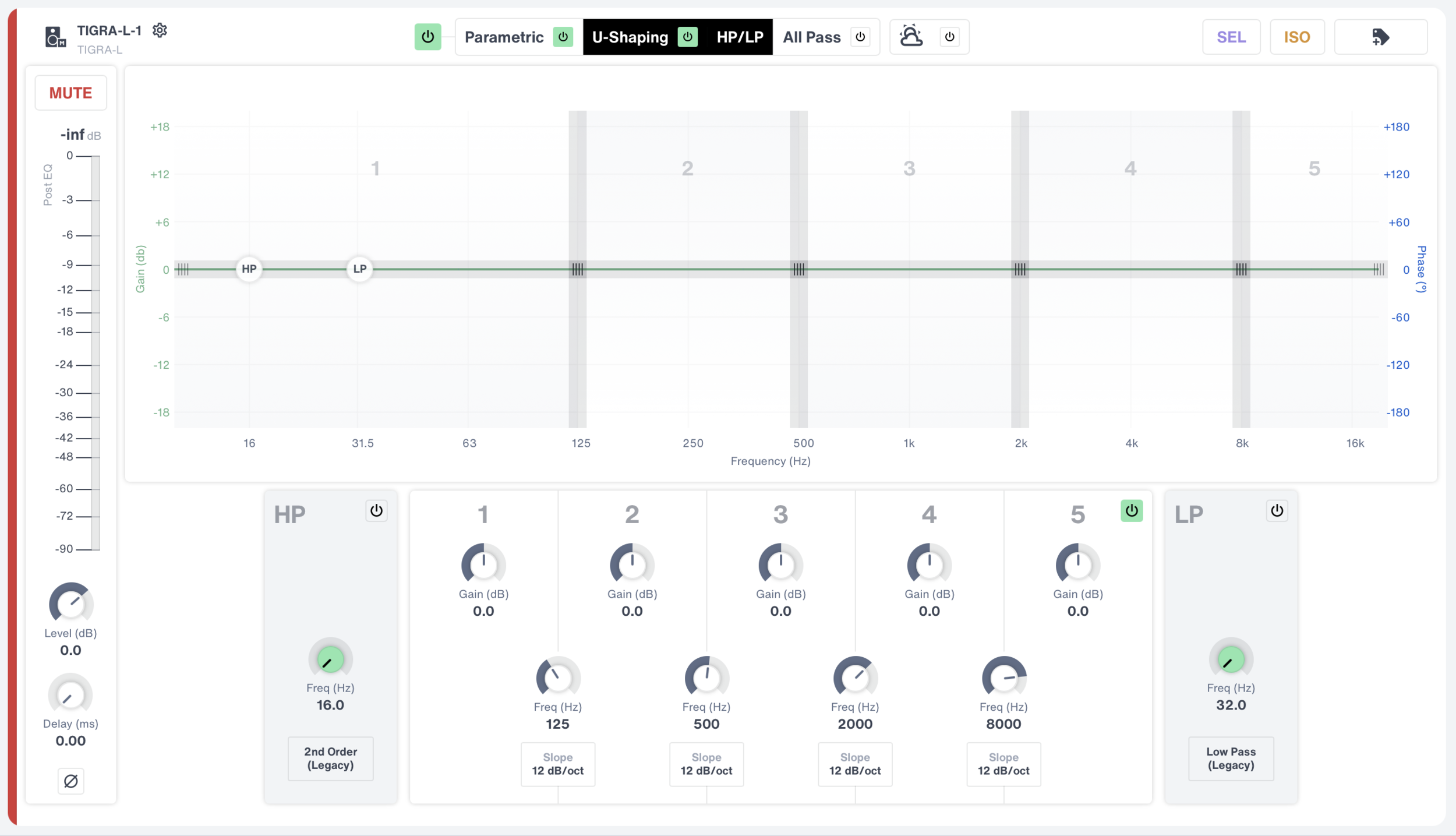
Nebra software provides user control of the signal processing included in the Type 3P GEN-1-enabled input module and displays Remote Product Monitoring (RPM) telemetry data.
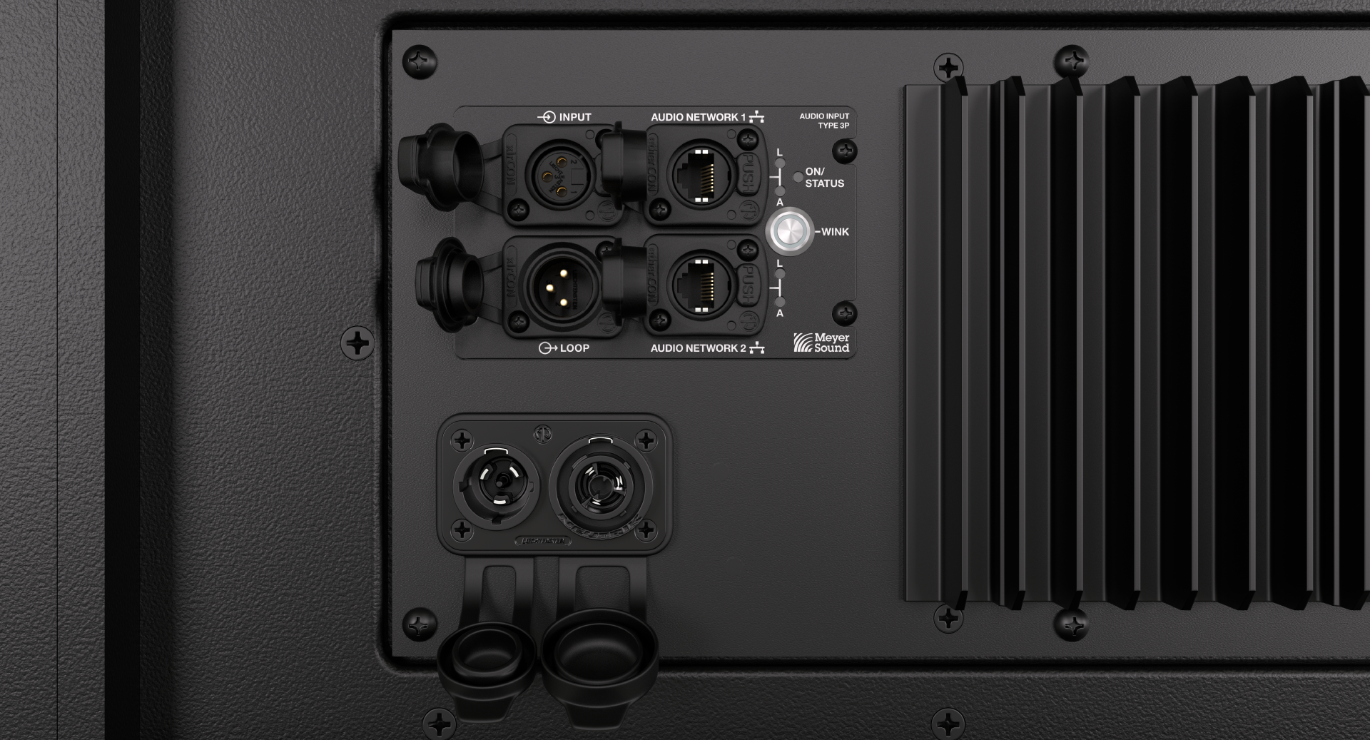
Pressing the WINK button on the loudspeaker user panel, or in Nebra, turns front and rear wink LEDs on and off for loudspeaker identification. The WINK button also facilitates resetting the onboard signal processing and the audio input format to analog.
Accessories
The MGB-T1 Grid Box connects the top TIGRA of an array to hoisting equipment if the array center of gravity falls within the extents of the grid box.
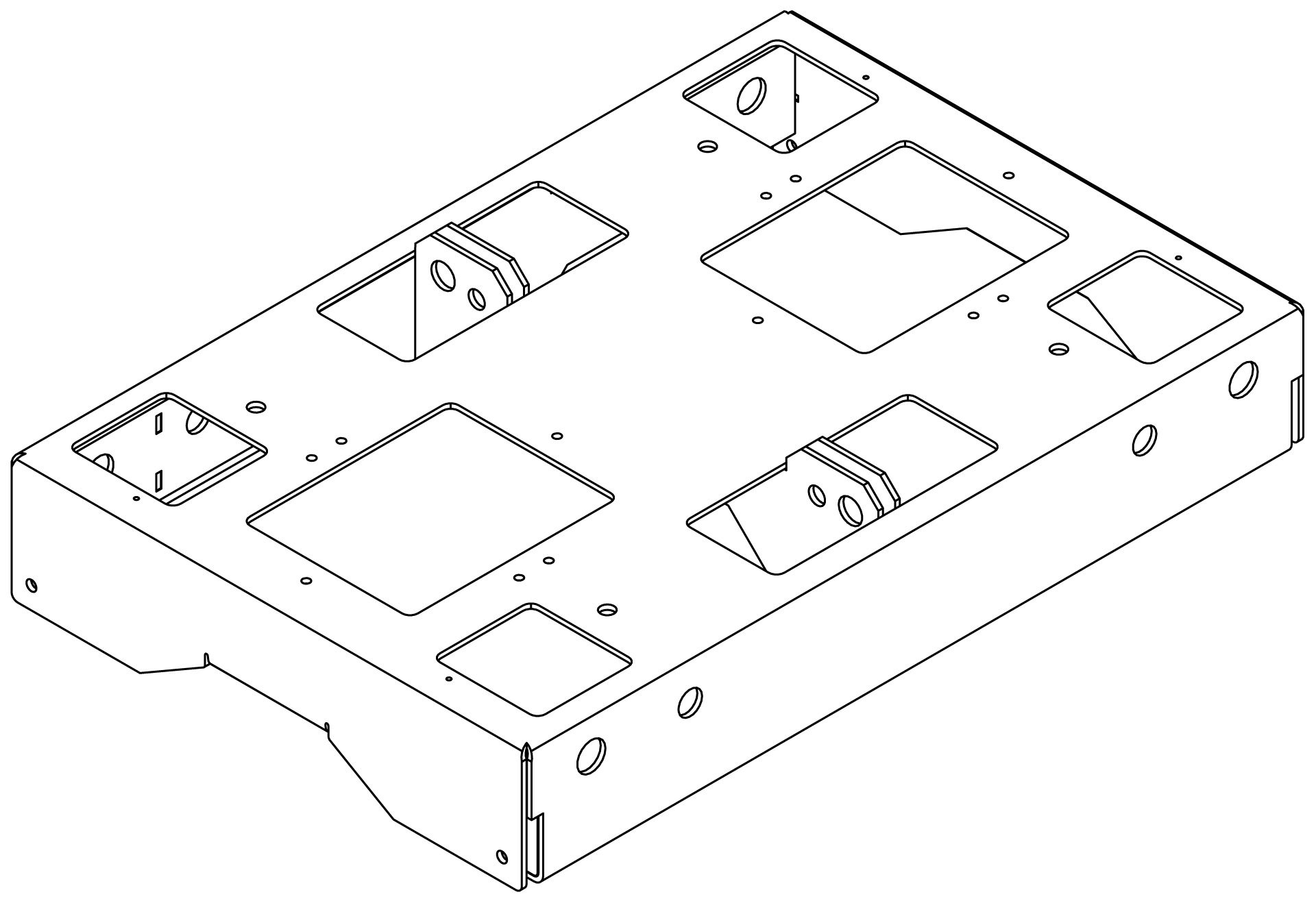
Part of the MTG-TIGRA Top Grid Kit and available separately, the MSB-T1 Shackle Bar connects to the MGB-T1 Grid Box to expand the maximum up/down tilt of an array. See TIGRA rigging for further details.
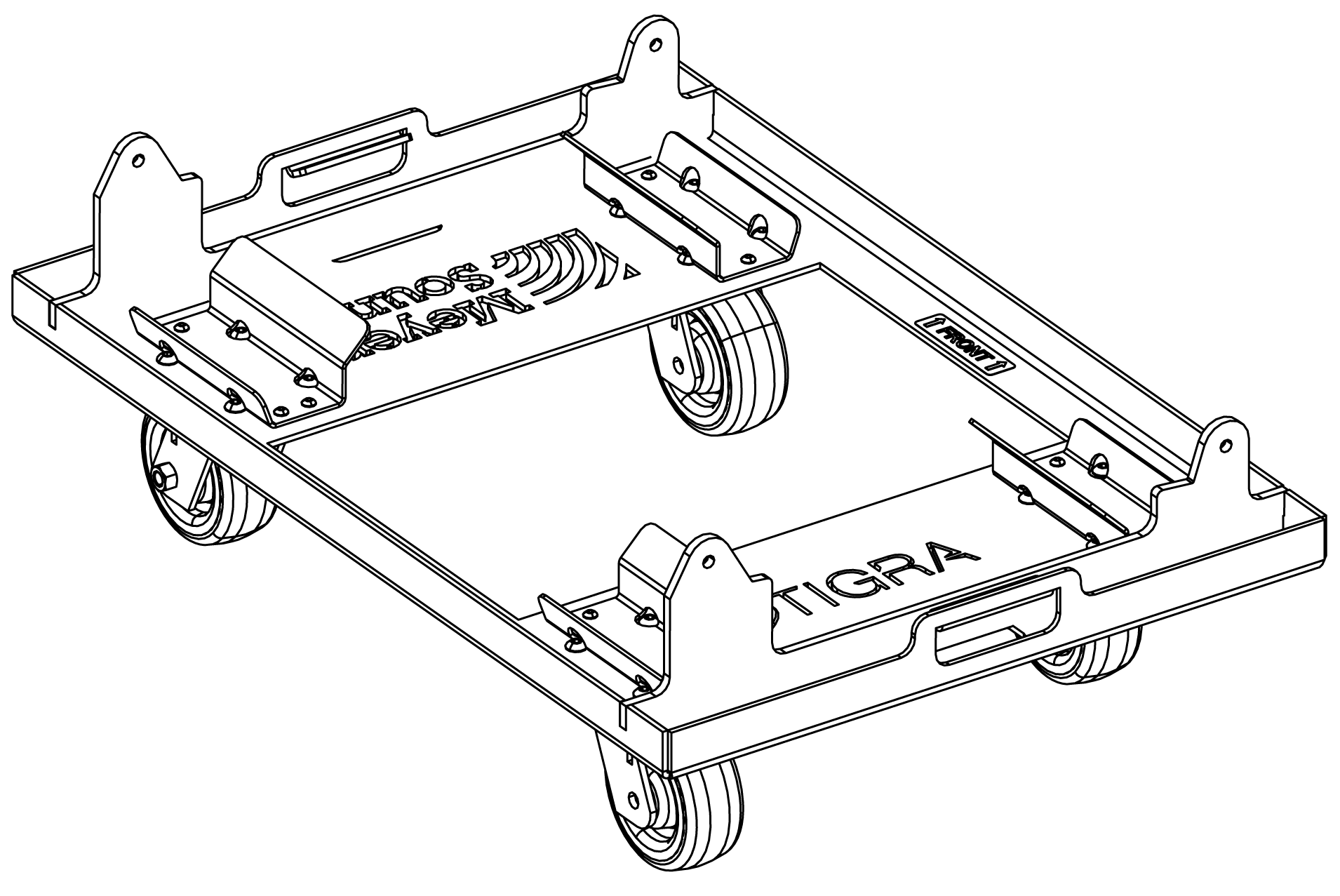
The MCF-T1 caster frame transports up to four TIGRA loudspeakers and aids in suspending arrays.
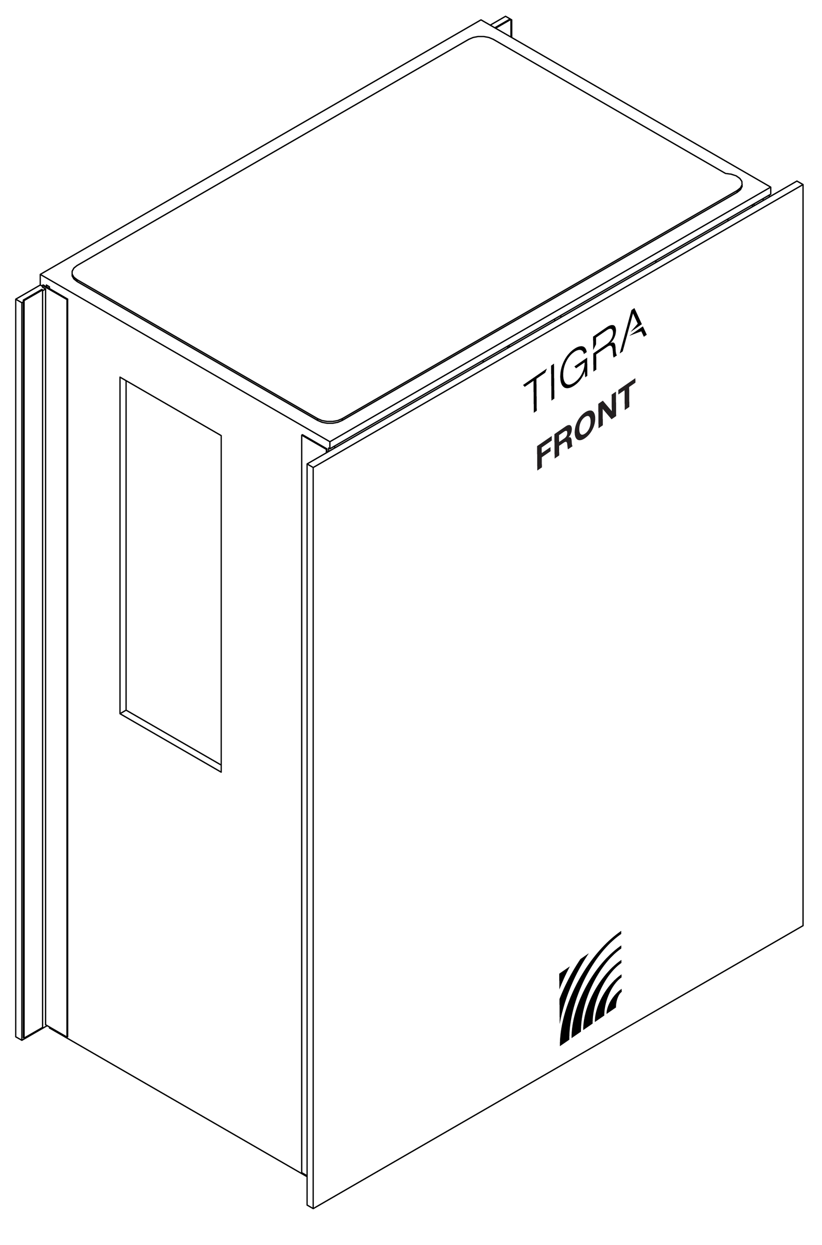
MPC4-T1 4-high Pullover Covers protect TIGRA loudspeakers when stored or transported.
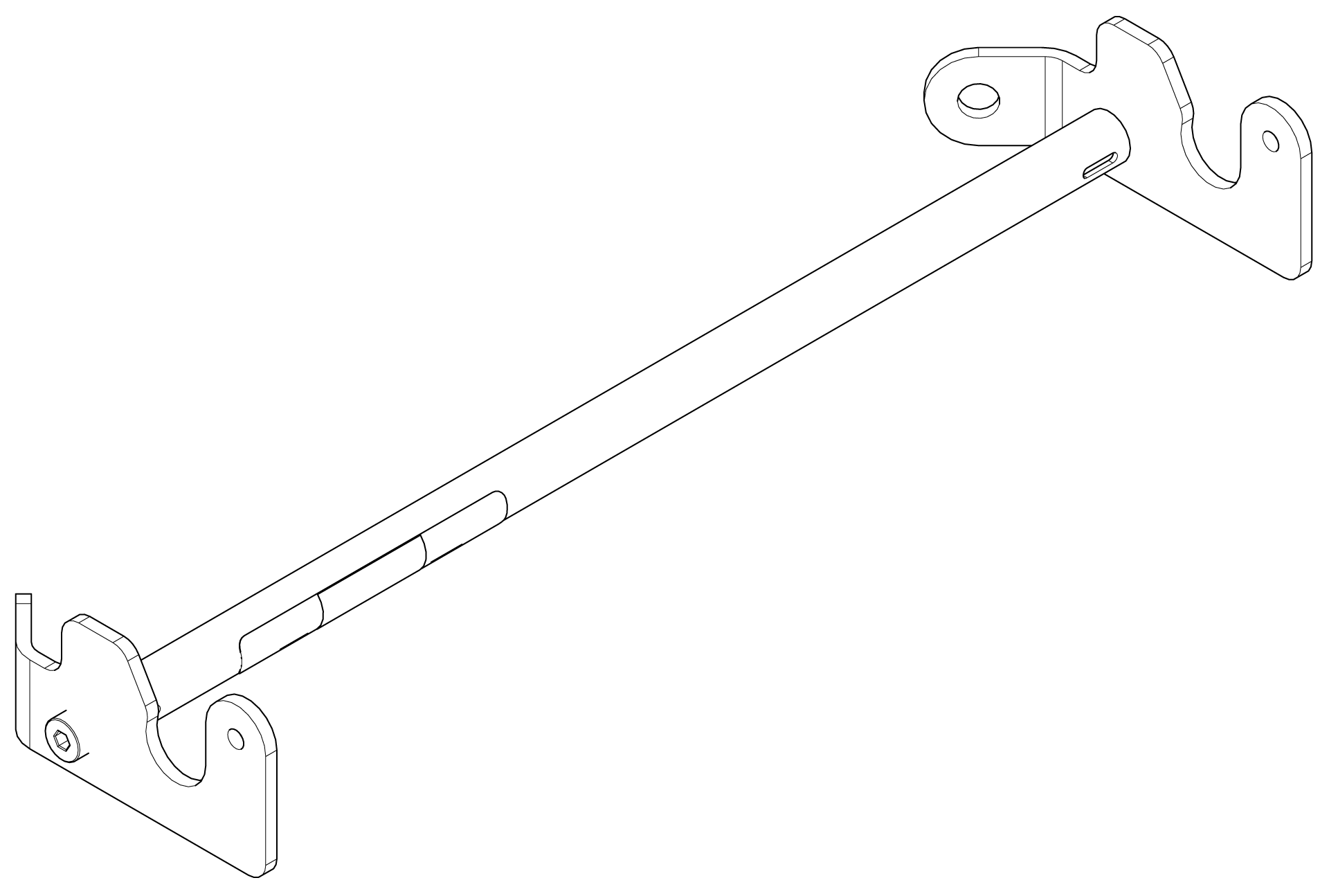
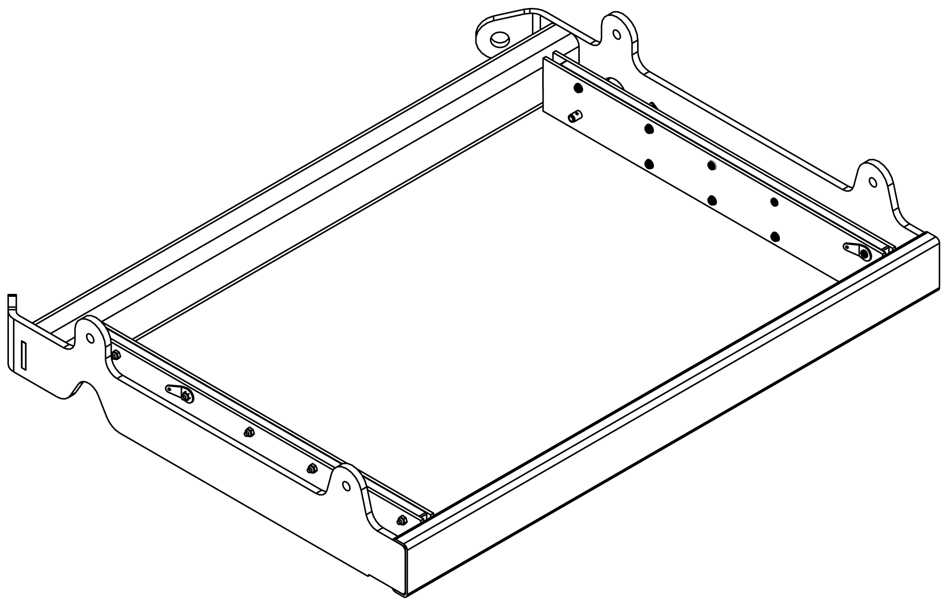
The MPBF-T1 Pull-back Frame connects the bottom of an array to a hoist for additional downtilt when not achievable with the MTG-T1 Top Grid Kit alone.
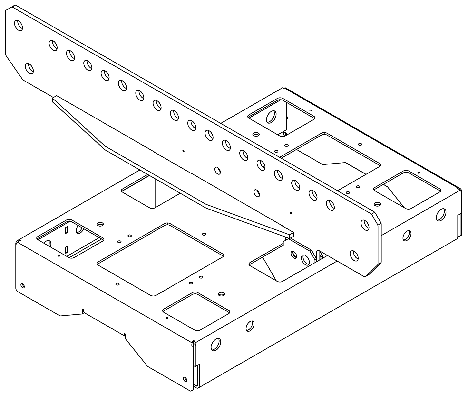
The MTF-T1 Transition Frame connects TIGRA loudspeakers under a PANTHER array.
The MVP Motor Vee Plate allows horizontal aiming of an array while suspended (shackles not included).
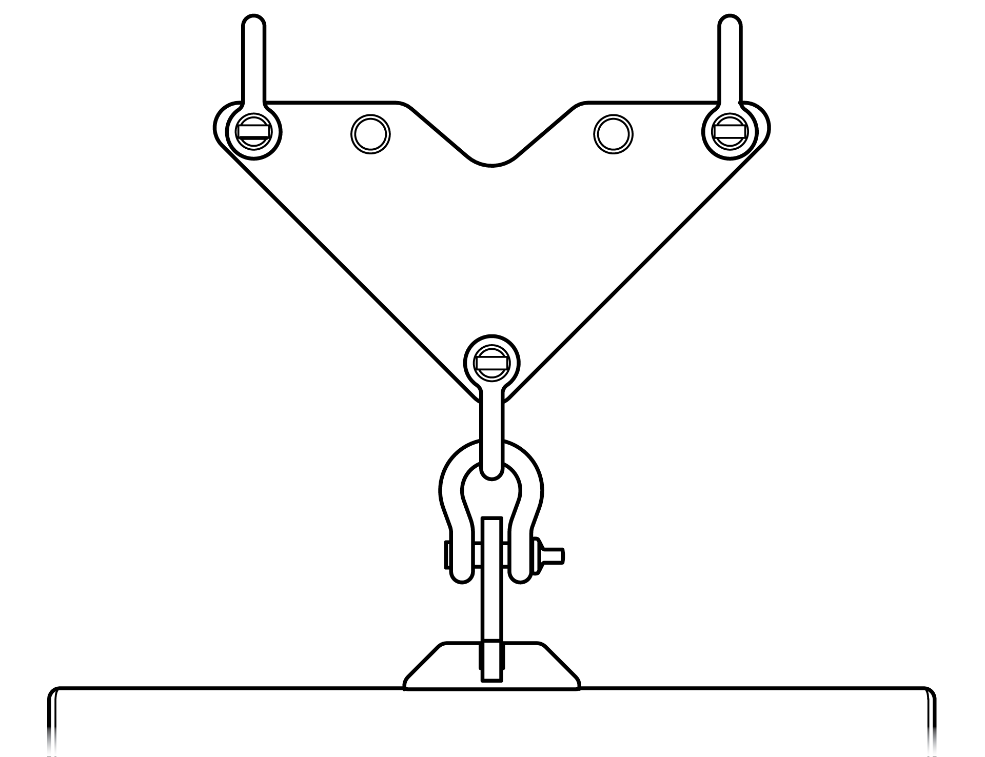
See TIGRA rigging for further details.
Electrical service requirements
Safe operation of TIGRA loudspeakers requires knowledge of proper power distribution, voltage, current, and electrical practices.
To avoid reproduction degradation and potential power-down due to insufficient voltage, provide sufficient power for full dynamic range reproduction of the input signal, especially at maximum output.
Use TIGRA only with professionally installed AC power systems that meet local electrical codes.
Input voltage protection and operating behavior
TIGRA loudspeakers incorporate protective circuitry to support stable operation under non‑ideal AC supply conditions.
If the AC input voltage drops below approximately 90 V, the loudspeaker may continue operating briefly using internally stored energy. If the input voltage does not return to the normal operating range, the loudspeaker will power off.
AC input above approximately 275 V exceeds power-supply limits and may damage the loudspeaker.
Caution
Always verify that AC power sources remain within the rated operating range specified in this manual.
Power supply
The power supply included in TIGRA loudspeakers prevents high inrush currents with soft-start power up, suppresses high-voltage transients up to several kilovolts, and filters common-mode and differential-mode radio frequencies (EMI).
Powering on
When powering on TIGRA loudspeakers, the following startup events take place over several seconds:
The On/status LEDs flash during initial startup.
Solid green On/status LEDs indicate the loudspeaker can reproduce audio.
Caution
After 15 seconds without solid green On/status LEDs, remove AC power and verify voltage and power-cable conductor termination. If blinking continues or solid green never appears, contact Meyer Sound Technical Support.
AC power distribution
Connect all audio components (self-powered loudspeakers, mixing consoles, and processors) to the AC power distribution while preserving line polarity. Tie all grounds to one common point using cable gauge equal to or larger than neutral and line conductors.
Caution
The nominal operational AC mains voltage range is 100–240 V AC.
The voltage between the earth/ground and line should never exceed 264 V AC or be less than 90 V AC
Before applying AC power to any Meyer Sound self-powered loudspeaker, make sure the voltage potential difference between the Neutral and earth/ground conductors is less than 5 V AC when using single-line AC wiring (LINE - NEUTRAL - EARTH/GROUND).
For safety, always use the earth/ground conductor
Improper earthing/grounding of connections between loudspeakers and the rest of the audio system may produce noise or hum or cause serious damage to the input and output stages of the system’s electronic components.
The following examples show one and two-line electrical distribution systems.
120V AC, single line
3-phase Wye system — line-neutral-earth/ground
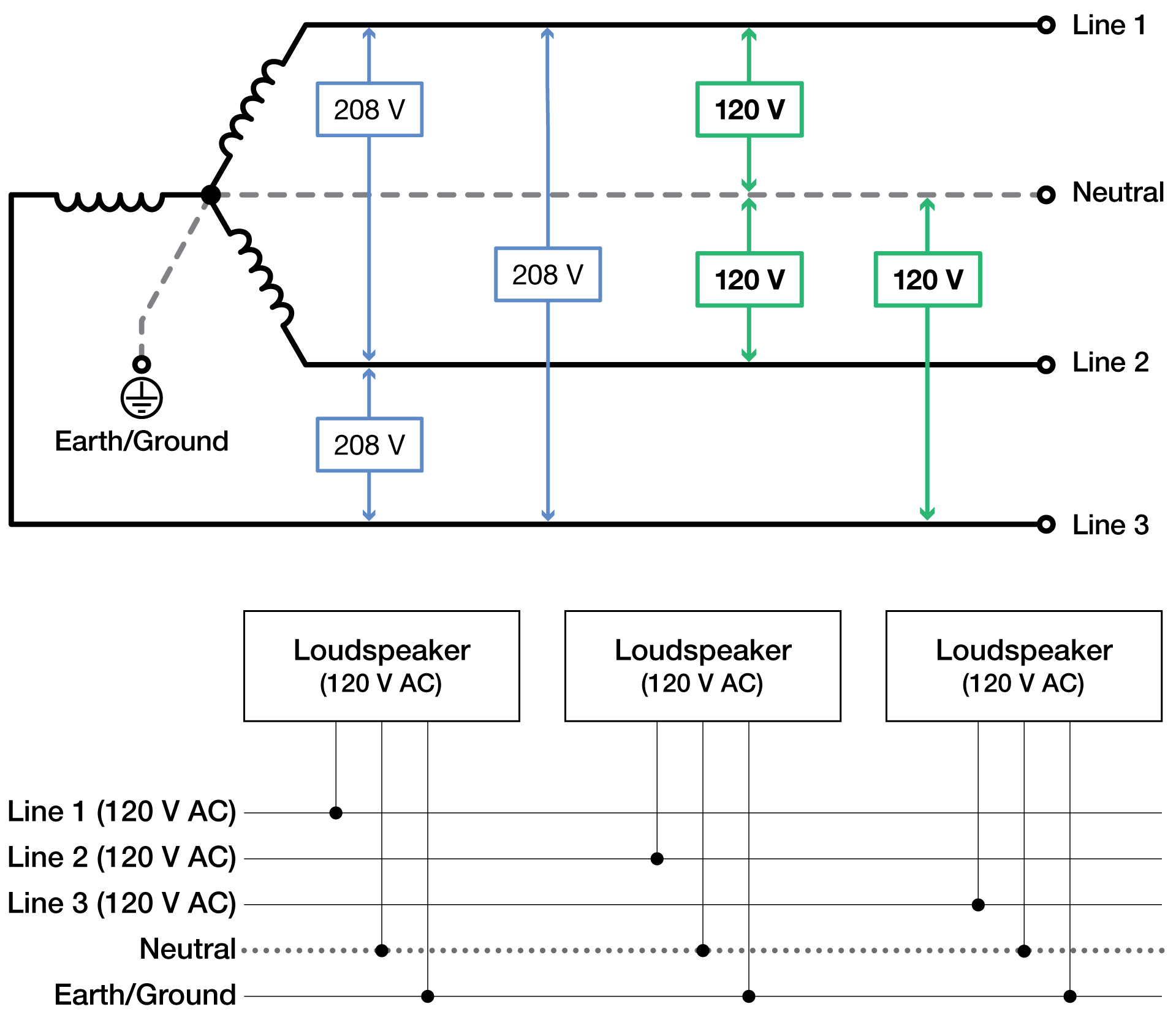
The figure below illustrates the secondary of a 120/208 V AC, 3-phase Wye distribution system with the loudspeaker load distributed across all three phases, with each loudspeaker connected to a single line, a common neutral, and earth/ground. This system and these connections deliver 120V AC to each loudspeaker.
120 V AC, two lines
3-phase Wye system — line-line-earth/ground
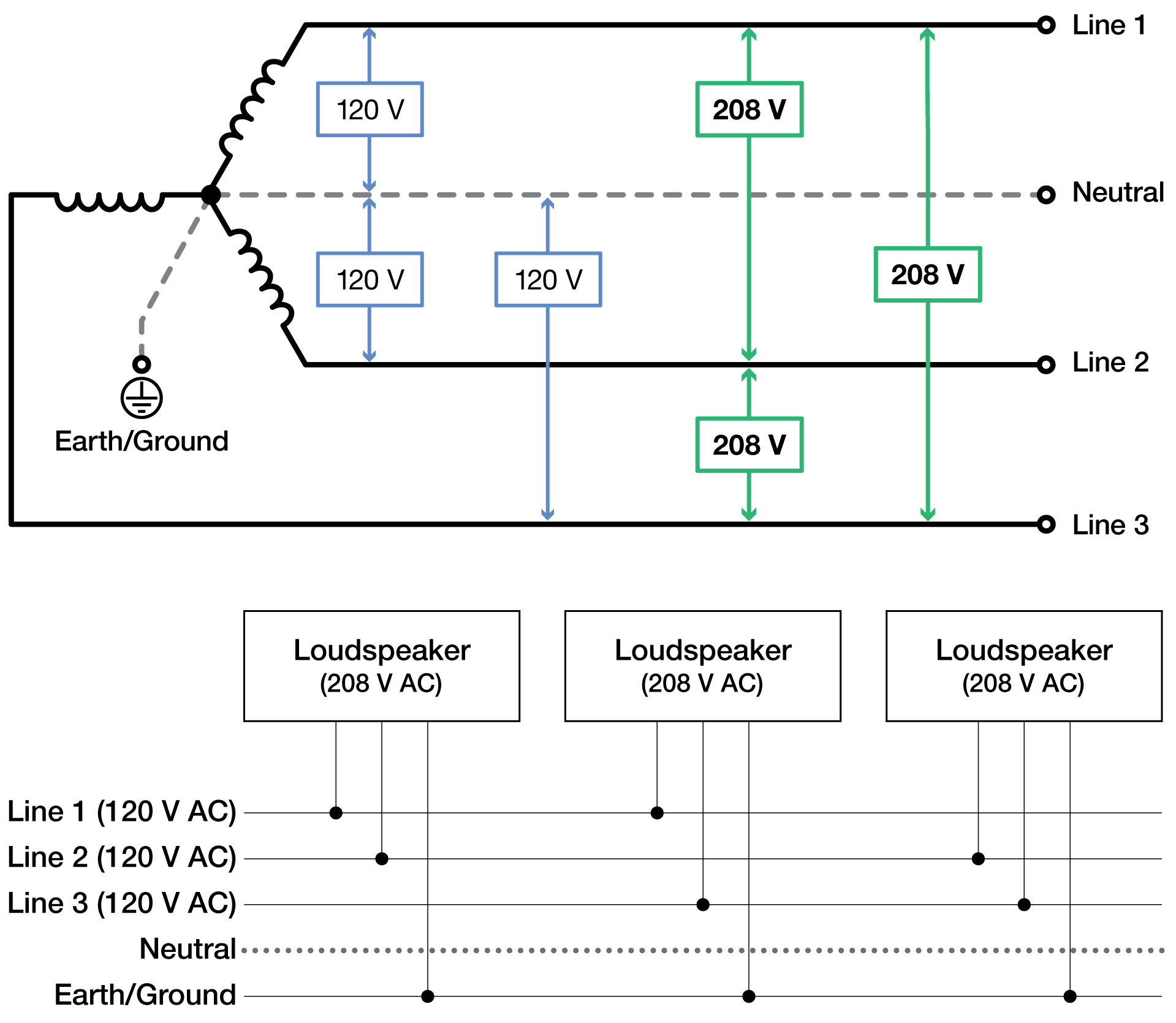
The figure below illustrates the secondary of a 120/208 V AC, 3-phase Wye distribution system with the loudspeaker load distributed across all three phases, with each loudspeaker connected to two lines, a common neutral, and earth/ground. This configuration is possible because TIGRA loudspeakers tolerate elevated voltages from the Earth/Ground conductor and do not require a Neutral line. This system and these connections deliver 208 V AC to each loudspeaker.
Recommended because it allows loudspeakers to draw less current than with single-line systems, this configuration thereby reduces voltage drop due to cable resistance. It also excludes the possibility of varying ground-to-neutral voltages, producing an audible hum.
240 V AC, single line
3-phase Wye system — line-neutral-earth/ground
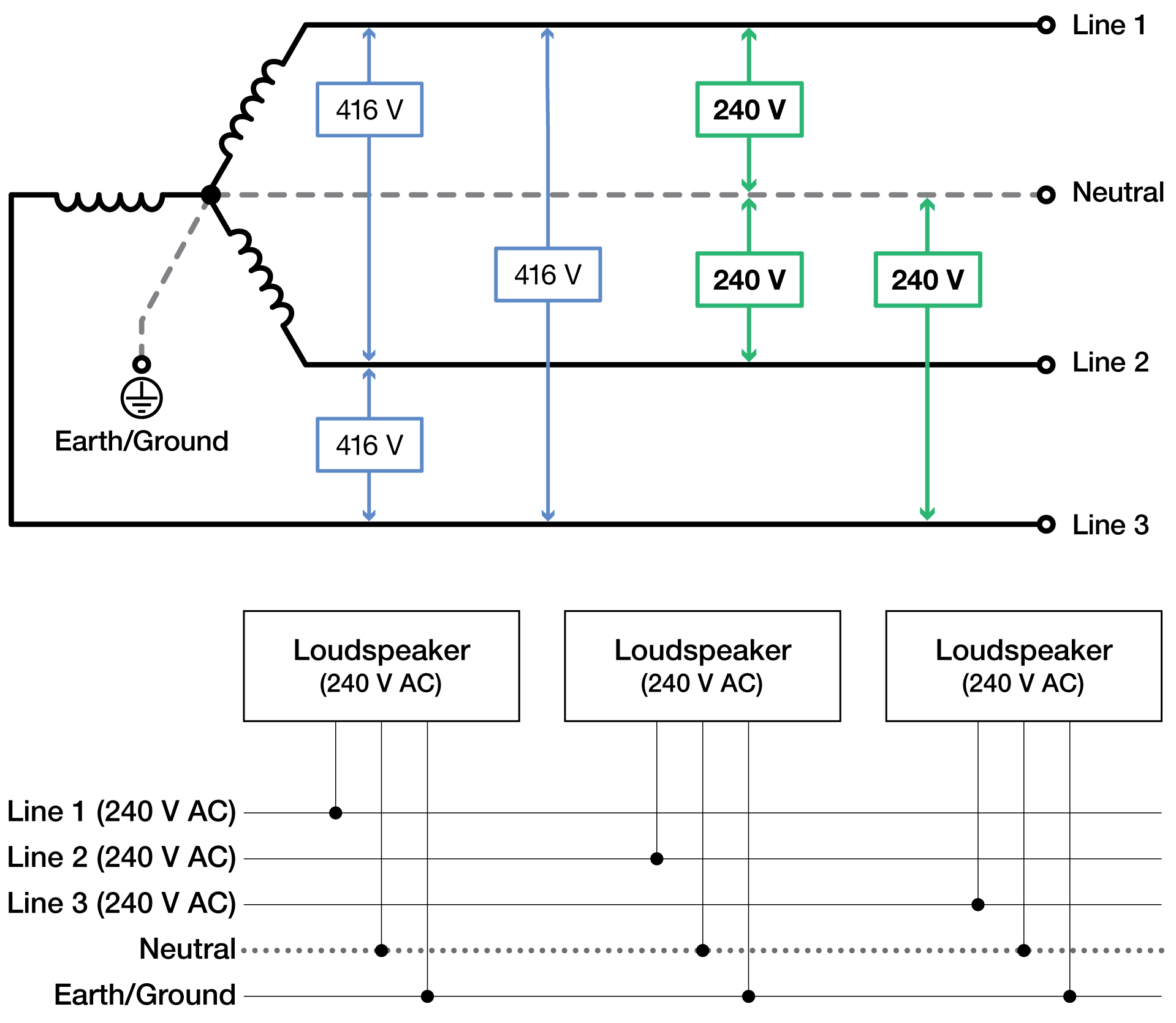
The figure below illustrates the secondary of a 240/416 V AC, 3-phase Wye distribution system with the loudspeaker load distributed across all three phases, with each loudspeaker connected to a single line, a common neutral, and earth/ground. This system and these connections deliver 240V AC to each loudspeaker.
Caution
For 240/416 V AC, 3-phase Wye distribution systems, never connect two lines to the AC inlet of TIGRA loudspeakers, which exceeds the upper voltage limit (264 V AC) and will damage the loudspeaker.
Circuit breaker requirements
Circuit protection devices for main and branch circuits of any power distribution system used in conjunction with TIGRA loudspeakers should react slowly to brief over-current occurrences, but respond immediately to short circuits, and comply with one of the following standards to avoid nuisance tripping.
IEC 61009, Type C trip curve
UL‑489, equivalent to IEC Type C trip curve (approximately 5-10 x inrush current)
Note
Many Residual Current Circuit Breakers (RCCB) are sensitive to high-frequency noise in the line-neutral path and may false/nuisance trip. If required, make certain the residual current device ignores or rejects high-frequency noise and artifacts. Line-to-Ground and Neutral-to- Earth/Ground capacitance can cause an imbalance between the current carrying conductors in a cable or a conduit, potentially causing RCCB nuisance tripping. Consult with a licensed electrician or electrical engineer when designing electrical distribution systems.
Power connectors
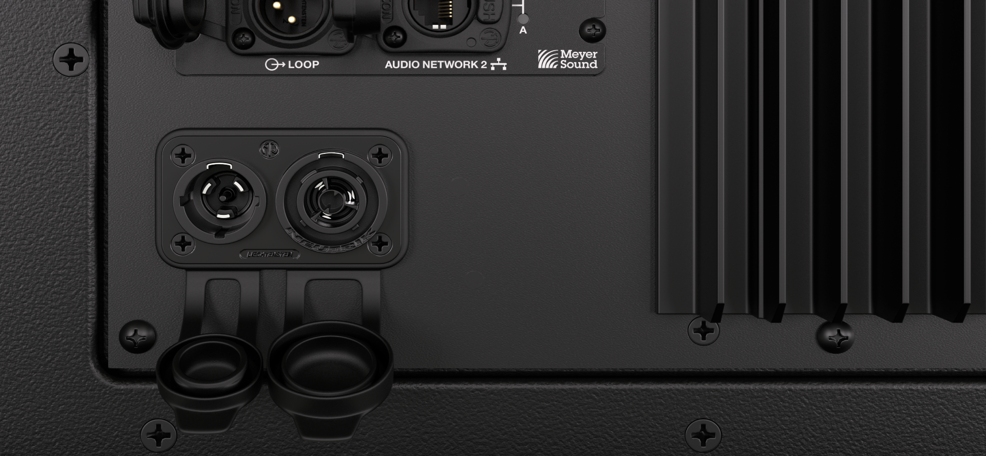
For AC power input and AC loop output, TIGRA loudspeakers have Neutrik powerCON® TRUE1 TOP‑series chassis connectors,
IEC 60320‑1 / EN IEC 60320‑1
UL 60320‑1
CSA C22.2 No. 60320‑1
When used with compatible cable connectors, the connector system supplies power to an appliance and provides power from an appliance to other equipment.
Connect only compatible powerCON TRUE1 cable connectors to the chassis-mounted AC connectors.
Caution
Connectors achieve IP65 protection only with properly assembled Neutrik powerCON TRUE1 cable connectors or fully inserted sealing caps.
Check the sealing caps for moisture before covering the connectors. If wet, dry the cap before covering the connector to avoid introducing liquid to the connectors.
Always seal the connector with the sealing cap when not in use.
Before connecting power cables, inspect the chassis-mounted AC connector assembly for secure mounting and damage.
AC input
The AC input connector supplies mains power to the TIGRA loudspeaker’s internal power supply.
Locking Neutrik powerCON® TRUE1 connector
Three conductors: line, neutral, and protective earth (PE)
Certified as an appliance inlet with breaking capacity in accordance with UL 60320‑1 and CSA C22.2 No. 60320‑1
Rated up to 20 A at 250 V AC in North America (UL/CSA)
Rated up to 16 A at 250 V AC in IEC regions (EN / IEC 60320‑1)
Make all loudspeaker audio and Ethernet connections while disconnected from AC power.
Caution
The applied AC supply must not exceed the voltage or current ratings specified for the connector, cabling, or upstream circuit protection.
AC loop output
The AC loop output connector provides AC pass‑through power from the loudspeaker to downstream equipment, and features:
The same AC voltage present at the AC Input
A locking Neutrik powerCON TRUE1 connector, which helps prevent accidental disconnection during operation
Appliance outlet breaking capacity in accordance with UL 60320‑1 and CSA C22.2 No. 60320‑1
Up to 20 A at 250 V AC in North America (UL/CSA) rating
Up to 16 A at 250 V AC in IEC regions (EN / IEC 60320‑1) rating
Caution
Exceeding allowable current ratings may result in tripped circuit breakers, voltage drop, or equipment damage.
AC looping - standard installed wall power circuits
For applications requiring multiple TIGRA loudspeakers, connect the AC loop output of the first loudspeaker to the AC input of the second loudspeaker, and continue this sequence as required.
The maximum number of TIGRA loudspeakers that can be AC-looped is limited by both circuit capacity and voltage drop in the power distribution system. If the supply voltage decreases, the current draw increases because the power supply delivers a constant amount of power (watts). Although the loudspeaker's average current draw may indicate that additional units could be supported, field testing has shown that cable resistance, branch-circuit impedance, and peak loudspeaker power demands can cause excessive voltage sag when more units share the same circuit. Limiting AC looping to three loudspeakers helps ensure reliable operation across a wide range of real-world electrical installations, reduces the likelihood of nuisance breaker trips, and maintains amplifier performance during high-output reproduction. For best results, use the shortest practical cable lengths and circuit protection devices with a Type C or equivalent trip characteristic.
The AC loop output provides pass‑through power only and does not include current limiting, over‑current protection, or power conditioning. The total current drawn by all connected loudspeakers must remain within the limits of the AC supply, cabling, and upstream circuit protection as specified in the following table:
Country | Voltage | Circuit breaker | Power cable | Looping Qty |
|---|---|---|---|---|
Japan | 100 V AC | 15 A | Japan 5-15 | 1 |
USA | 115 V AC | 20 A/15 A | NEMA 5-15 wall plug is 15A derates to 12A | 1 |
EU | 230 V AC | 16 A | CEE7/7 wall plug is 16A EU has no derating | 3 |
USA | 240 V AC | 20 A | NEMA L6-20 wall plug is 20A derates to 16A | 3 |
Note
These limits assume typical program material and proper AC distribution.
Lower line voltages reduce the number of loudspeakers per circuit.
Locking Neutrik powerCON TRUE1 connectors protect against unintended disconnection.
Maintain protective earth continuity across all AC connections, including loop-through cabling.
Verify circuit capacity before connecting multiple loudspeakers to a single source.
See Circuit breaker requirements for more information.
Wiring AC power cables
TIGRA loudspeaker AC power cables must use powerCON TRUE1 cable connectors certified to UL 60320‑1 / CSA C22.2 No. 60320‑1.
Qualified personnel must assemble cables according to local electrical regulations.
Caution
Improperly wired or damaged AC power cables may present an electrical hazard.
Voltage and power requirements
TIGRA loudspeakers have a universal, multi-voltage power supply that automatically adapts to AC voltage for worldwide operation without user configuration.
Parameter | Specification |
|---|---|
Input voltage | 100–240 V~ |
Frequency | 50–60 Hz |
Input current | 5.5–2.3 A |
Maximum power consumption | 550 W |
The AC input uses a locking Neutrik powerCON TRUE1 TOP appliance-certified inlet with a breaking capacity of 20 A in North America, 16 A in Europe/IEC.
Parameter | Specification |
|---|---|
Output voltage | 100–240 V~ |
Frequency | 50–60 Hz |
Maximum looping current | 6.5–13.7 A (system‑dependent) |
Output current rating | 12–16 A |
The AC loop output uses a locking powerCON TRUE1 TOP appliance-certified inlet with a breaking capacity of 20 A in North America, 16 A in Europe/IEC.
Amplification and audio
TIGRA Type 3P input modules provide Milan AVB and analog audio inputs, while Nebra software controls EQ, delay, gain, Low-Mid Beam Control, input switching, RPM telemetry, and Wink over Ethernet.
Network transport of Milan AVB digital audio requires specific network switch capabilities. See Recommended Network Switches for Milan AVB Systems for information on network switch requirements.
Factory reset
To reset both the onboard user-controlled signal processing to the factory defaults and the audio input type to analog, apply power to the loudspeaker, then:
In Nebra, select Device List, right-click the listed device, then select Reboot device to factory default.
- OR -
At the loudspeaker, press and release WINK once, then hold WINK for 10–13 seconds. During rapid LED blinking, release WINK to initiate a factory reset. Hold about 20 seconds until the LEDs stop blinking to cancel the reset.
Select the input type
To select the input type (analog, Milan AVB):
Connect the loudspeaker directly to a computer running Nebra or to a network that includes a computer running Nebra.
In the Processing tab, select Processing Overview, and select a device.
In the Meter column, next to the input meter, select the up/down arrows to change input format type.
Update firmware
Nebra can update the firmware for all Meyer Sound loudspeakers and devices, including:
Type 3P, GEN-1
Nadia
GALAXY
Type 3M, MEP
MPS-X
Bluehorn GALAXY
CAL
RMServer
There are two ways to update the firmware of connected Meyer Sound Milan AVB devices using Nebra:
Automatic download
Manual install
Automatic download
When you open Nebra and the computer is connected to the Internet, it automatically downloads the latest firmware versions.
If a newer firmware version is available for a device that needs updating, a notification banner displays at the top of the application window.
Select View Details in the firmware notification banner.
Select Install for each device, or Install All to install the current version of device firmware.
Manual install
If you have a firmware file, use the following procedure to individually update devices manually.
Copy the firmware file to the computer running Nebra.
In
 Devices, right-click a device, then select Manual firmware install.
Choose the firmware file, then select Open.
On/Status LED
The On/Status LED indicates the state of the loudspeaker:
Off — | Loudspeaker not powered |
Green blinking — | Loudspeaker starting up |
Green — | Ready to reproduce the input signal |
Red flash — | Audio input clipped (solid red during clipping) |
Yellow — | RMS limiting engaged (displayed for at least 1 second, longer if limiting continues) |
Red blinking — | An error has occurred. Connect to Nebra software to display additional information. |
Warning
If the On/Status LED does not turn solid green within 15 seconds, disconnect AC power, verify 100–240 V AC supply voltage, and confirm correct power cable conductor terminal connections.
Network connector LEDs
The LEDs next to the network connector indicate (L) link speed and (A) activity.
(L) amber LED | (A) green LED | Indication |
|---|---|---|
off | off | no link/connection |
off | on | 100Base-Tx link with no activity |
off | blinking ≥ 2 Hz | 100Base-Tx link with activity |
on | off | 1000Base-Tx and above, link with no activity |
on | blinking ≥ 2 Hz | 1000Base-Tx and above, link with activity |
Limiting
The Limit On/Status LED signals excessive level. If limiting starts before the desired acoustic output, add loudspeakers or use models with higher output capability.
The loudspeaker meets acoustical specifications at normal temperatures while the LED stays green or limiting occurs only briefly. Limiting changes the On/Status LED from green to yellow for at least one second and reduces channel gain. A steady yellow LED indicates active limiting. The limiter protects drivers, reduces peak-related amplifier distortion, preserves headroom, and maintains smooth frequency response at high levels.
Continuous limiting indicates operation near system limits and can cause:
No added output from increased input level
Increased distortion from clipping and nonlinear driver operation
Excessive driver heat and excursion, shortened driver life, and possible damage
When source levels drop below the limiter threshold, the LED turns green and limiting stops.
Conventional limiters can limit too early because they assume fixed driver impedance. Driver impedance changes with signal level and voice coil and magnet temperature, reducing headroom and dynamic range. Meyer Sound TruPower® limiting measures current and voltage to calculate actual voice coil power dissipation. This method maximizes SPL across the driver’s frequency range, preserves signal peaks, reduces power compression at sustained high levels, regulates voice coil temperature, and extends transducer life.
Wink function
The bi-directional wink function identifies physical loudspeakers listed in Nebra.
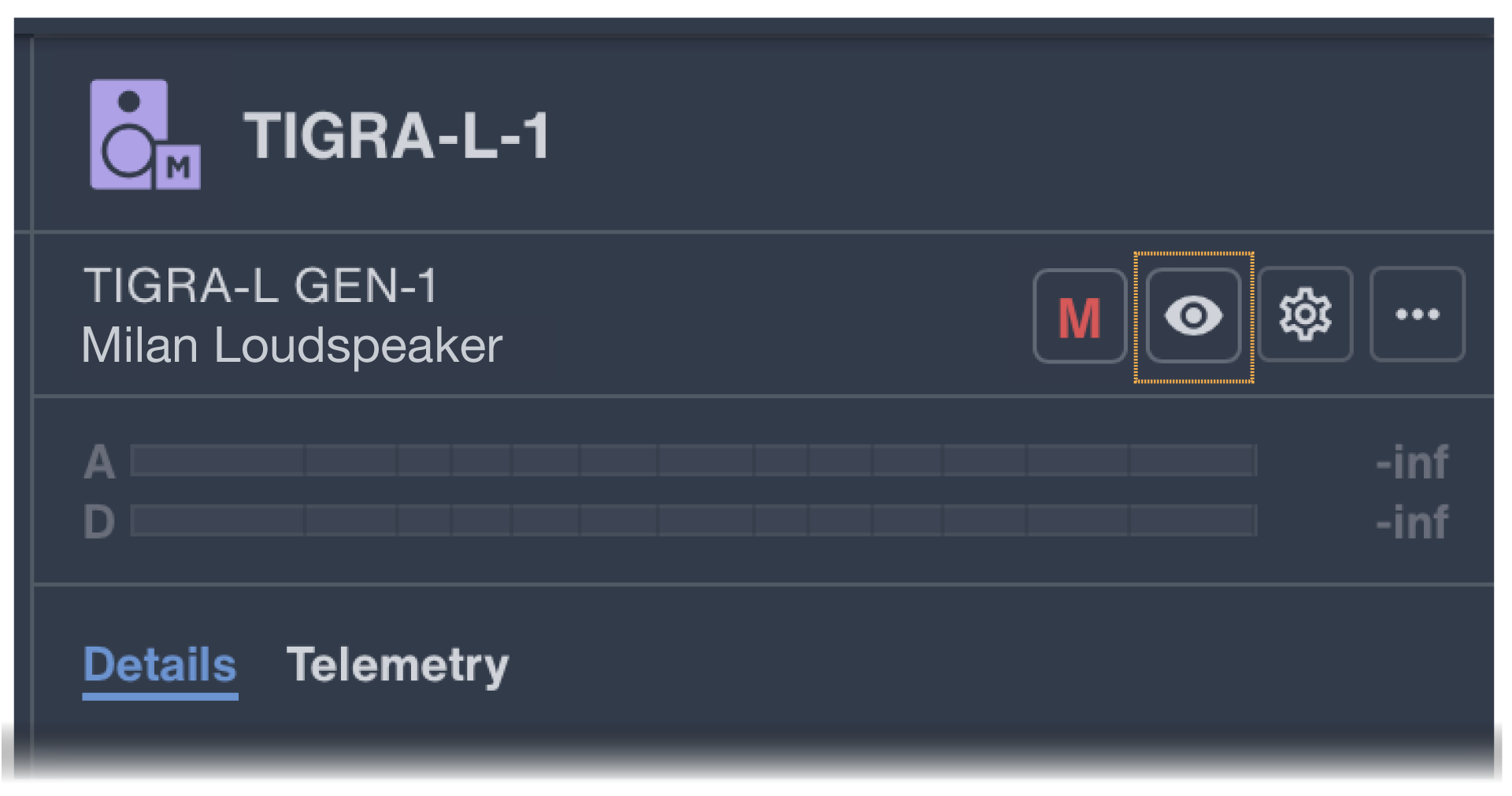
When active, Wink appears in Nebra on the Type 3P module WINK button/LED and on both grille LED bars. Wink times out after 10 seconds. In Nebra, activating Wink for a loudspeaker folder winks each loudspeaker in sequence for 5 seconds.
Devices — Identify (wink) a device
You can identify Meyer Sound devices using the wink function, which flashes LEDs on the front or rear panel.
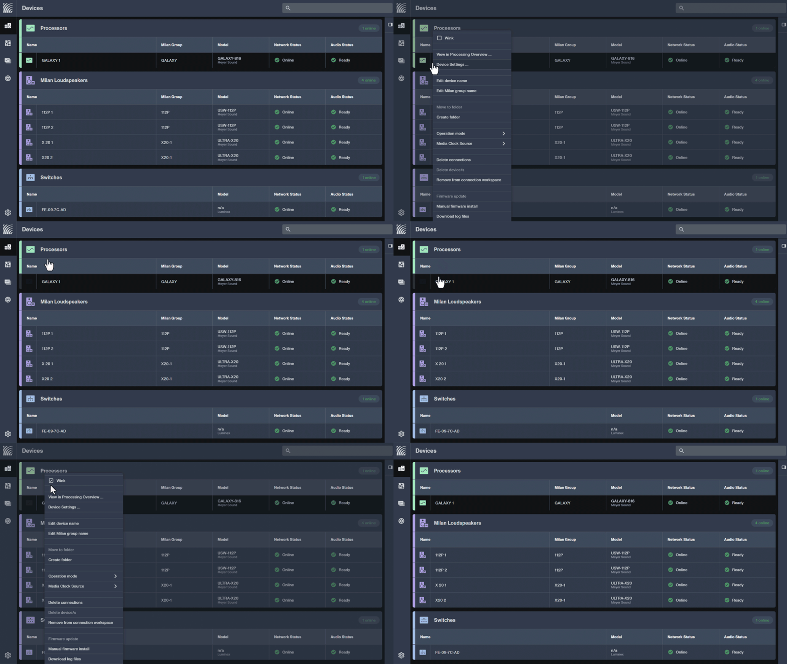
In
Devices, right-click a device to identify and check Wink. Repeat to wink multiple devices.To turn off Wink, right-click the device again and uncheck Wink.
To activate Wink at the loudspeaker, press and hold the Wink button down while watching the Limit/On/Status LED, which turns red and then off, then release the WINK button. The WINK LED turns yellow for 10 seconds. If the WINK button remains pressed, the Limit/On/Status LED will turn red again, and the Wink function will remain off.
To turn Wink off at the loudspeaker, wait 10 seconds or press and hold the Wink button — the On/Status LED will turn red. Wait until the On/Status LED turns off, then release the Wink button.
Remote Product Monitoring (RPM)
After connecting the network, power on the loudspeakers and open Nebra software. Nebra lists connected loudspeakers, status, and monitored parameters, including amplifier voltage, limiting activity, power output, fan speed, and driver status.
Audio input/loop output
The Type 3P input module includes two Neutrik etherCON TOP connectors for digital audio input, onboard signal processing control, and RPM data display in Nebra software, plus two 3-pin Neutrik XLR TOP connectors for analog audio input and loop output.
Warning
Analog and network chassis connectors provide outdoor protection (IP65, UL50E) only with mated Neutrik TOP cable connectors or fully inserted sealing caps.
Check sealing caps for moisture before covering connectors; dry wet caps first to prevent liquid entry.
Seal unused connectors with sealing caps.
Replace damaged or leaking sealing caps.
Network connections
For RPM telemetry and onboard DSP control only, connect each loudspeaker to a standard Ethernet network using IEEE 802.3-compliant switches that support at least 100 Mb/s full-duplex. Looping or daisy-chaining loudspeaker network connections is not supported due to increased latency and to minimize the impact of a cable failure.
To make Milan AVB connections to loudspeakers, in Nebra software, connect loudspeakers to available Milan AVB stream channels, including Galileo GALAXY and NADIA processors.
Switch-to-switch links require 1 Gb/s. Switch-to-Type 3P links use 100 Mb/s, allowing CAT5/6 cable splitting: two pairs for one Type 3P connection and two pairs for another, typically split in the network fanout connector.
Milan AVB digital audio connections
Nebra software provides the interface to make digital audio connections between send and receive devices.
The transmitting device must generate the following stream formats for connection to the Type 3P module:
Data Encapsulation | PCM |
Data Format | AAF |
Packet Bit Depth | 32 fixed |
Audio Bit Depth | 24-bit |
Number of Channels | 1, 2, 3, 4, 5, 6, 7, 8 |
Sample Rate | 96 kHz only |
Samples per PDU (Protocol Data Unit) | 12 (96 kHz) |
NADIA modules and Galileo GALAXY processors both transmit Milan AVB streams compatible with Type 3P input modules. For more information on Milan AVB, see User Guide — Managing AVB Networks.
Milan AVB stream connection
For the most current information, please see Nebra Help for steps to make Milan AVB connections between devices. Before making Milan AVB connections, mute the loudspeaker(s) to avoid any unintentional, potentially very loud sound reproduction.
Analog audio input (3-pin XLR female)
The 3-pin XLR female input connector accepts balanced audio signals with an input impedance of 10 kOhm. The connector uses the following wiring scheme:
Pin 1 — 1 kOhm to chassis and earth/ground (ESD clamped)
Pin 2 — signal (+)
Pin 3 — signal (–)
Case — earth (AC) ground and chassis
Pins 2 and 3 carry the differential input signal. Pin 1 connects to Earth/Ground through a 1 kOhm, 1000 pF, 15 V clamped network, providing virtual ground lift at audio frequencies while bleeding unwanted signals to ground. Use balanced XLR cables with pins 1, 2, and 3 connected at both ends; do not connect signal ground at only one end.
Shorting signal ground to the connector case may create a ground loop and hum.
If the loudspeaker produces unwanted noise or hiss, disconnect the audio signal cable from the input. If the noise stops, the loudspeaker likely functions correctly. Check the audio cable, source audio, AC power, and electrical ground.
Analog input and loop connectors
Wire looped loudspeaker cabling pin-to-pin, Pin 1 to Pin 1, Pin 2 to Pin 2, and so on, to prevent reversed polarity. Reversed polarity in one or more loudspeakers significantly degrades frequency response and coverage.
The loop output connector connects in parallel with the input connector and passes the unbuffered source signal, even without loudspeaker power.
Calculating analog input load impedance
Most source devices, such as processors and mixers, can drive loads at least 10 times their output impedance, typically 500–20,000 Ω for 50–2000 Ω outputs.
A Galileo GALAXY analog output, with 50 Ω output impedance, can drive up to 20 Meyer Sound 10 kΩ-input loudspeakers without distortion.
To avoid distortion when looping loudspeakers, confirm the source device can drive the total load impedance and produce +24 dBu into 50 Ω for maximum peak SPL. Cable capacitance, especially over 500 ft of typical balanced cable, can reduce high-frequency transmission and cause distortion; with a 50 Ω output, limit loops to 10 loudspeakers in most applications.
To calculate loop load impedance, divide 10 kΩ by the number of loudspeakers. For example, ten TIGRA loudspeakers create a 1000 Ω load. Since source devices should drive loads at least 10 times their output impedance, this loop requires 100 Ω output impedance or less.
Analog audio loop output (3-pin XLR male)
The 3-pin XLR male loop output connector loops one audio source to multiple loudspeakers and follows the same wiring as the Input connector. Connect each loudspeaker’s loop output to the next loudspeaker’s Input.
Amplifier cooling
The TIGRA amplifier module uses convection cooling. Keep airflow unobstructed around the rear heat sink, with at least 12 in (30 cm) behind the array, 3 ft (1 m) above it, and, for soffit-mounted arrays, 12 in (30 cm) on each side.
Grille removal
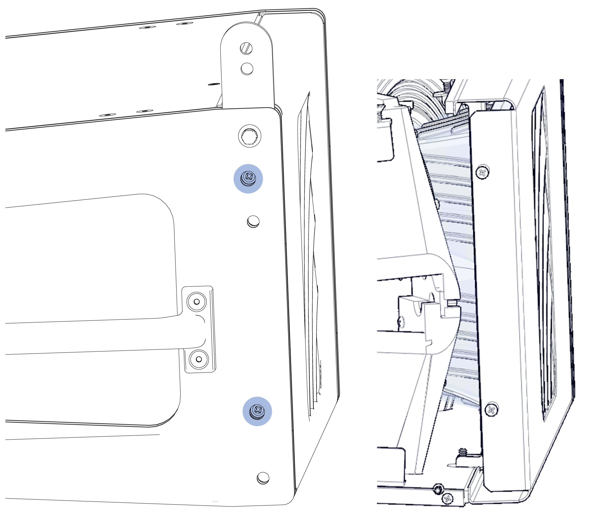
Four side-access Phillips head screws secure the grille. Remove the quick-release pins securing the front links, then rotate the links up to access the top screws.
TIGRA rigging
Safety statement for rigging
READ THIS STATEMENT CAREFULLY IN ITS ENTIRETY |
It contains important information regarding safety issues, including guidelines for general safe use of rigging systems as well as advisories on government regulations and liability laws.
This statement assumes that the owners and/or users of a Meyer Sound QuickFly® system are knowledgeable and experienced in the areas of rigging and flying loudspeaker systems. Many issues of crucial concern, such as the determination of appropriateness and condition of venue rigging points, cannot be addressed here. Therefore, the user must assume all responsibility for the appropriate use of QuickFly systems in any particular location or circumstance.
The suspension of large, heavy objects in public places is subject to numerous laws and regulations at the national/ federal, state/provincial, and local levels. The user must assume responsibility for making sure that use of any QuickFly system and its components in any particular circumstance or venue conforms to all applicable laws and regulations in force at the time.
GuideALinks
GuidALinks provide connection to the MBG-T1 Box Grid or to TIGRA loudspeakers above. Each loudspeaker includes four captive GuideALinks, two in the front, two in the rear. Located at the top corners of the cabinet, the GuideALinks extend or rotate into the GuideALink sockets of the grid box or into the GuideALink sockets of the cabinet above it in an array.
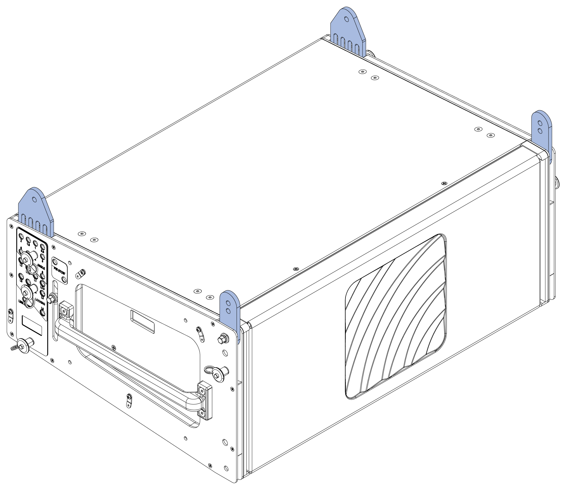
Raise, lower, or rotate GuideALinks only by the hexagonal knob, then secure them with lanyard-attached quick-release pins from the TIGRA end frame.
Caution
Never grasp the GuideALink itself to move it. Always use the square-shaped knob to raise, lower, or rotate GuideALinks to avoid hand injury.
Front GuideALinks
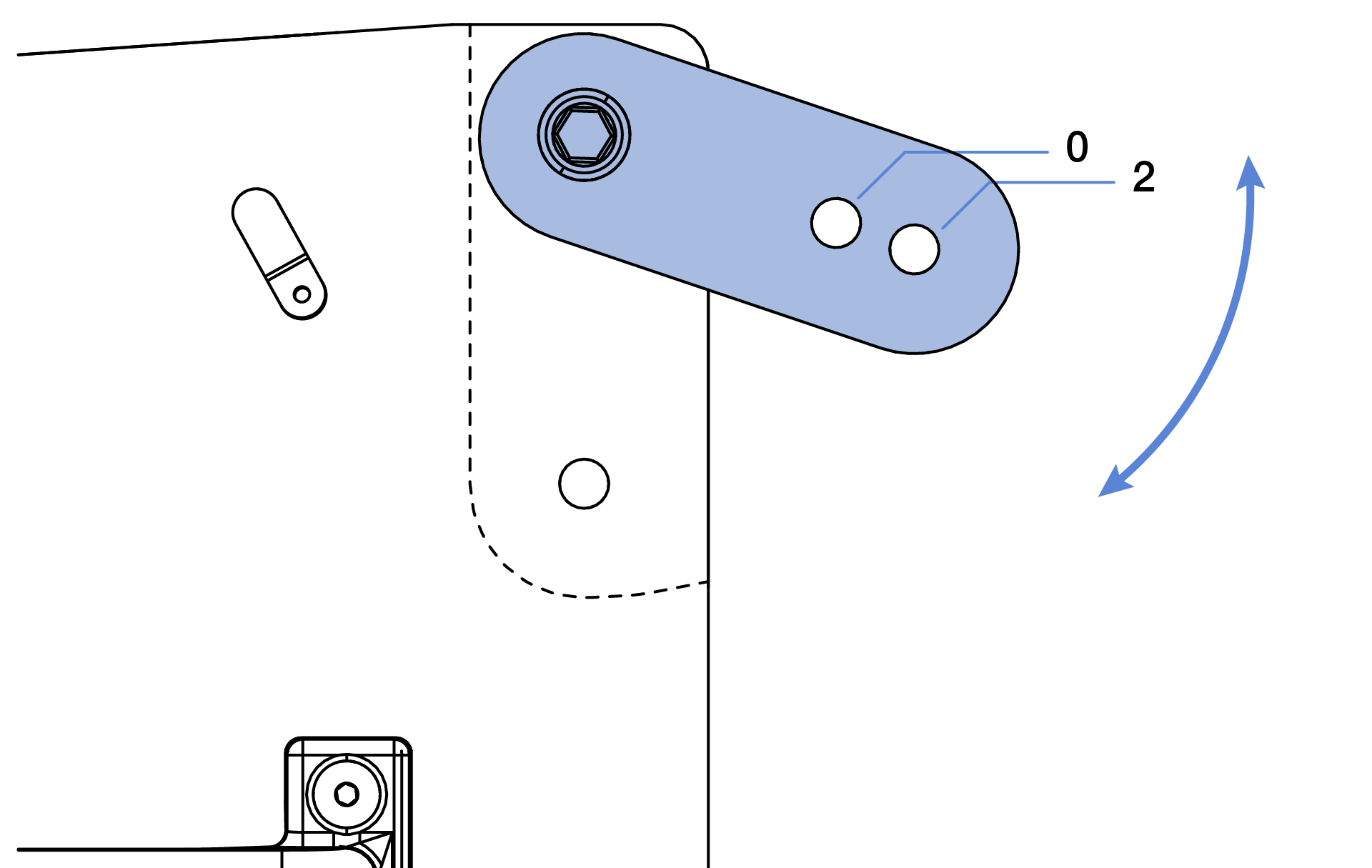
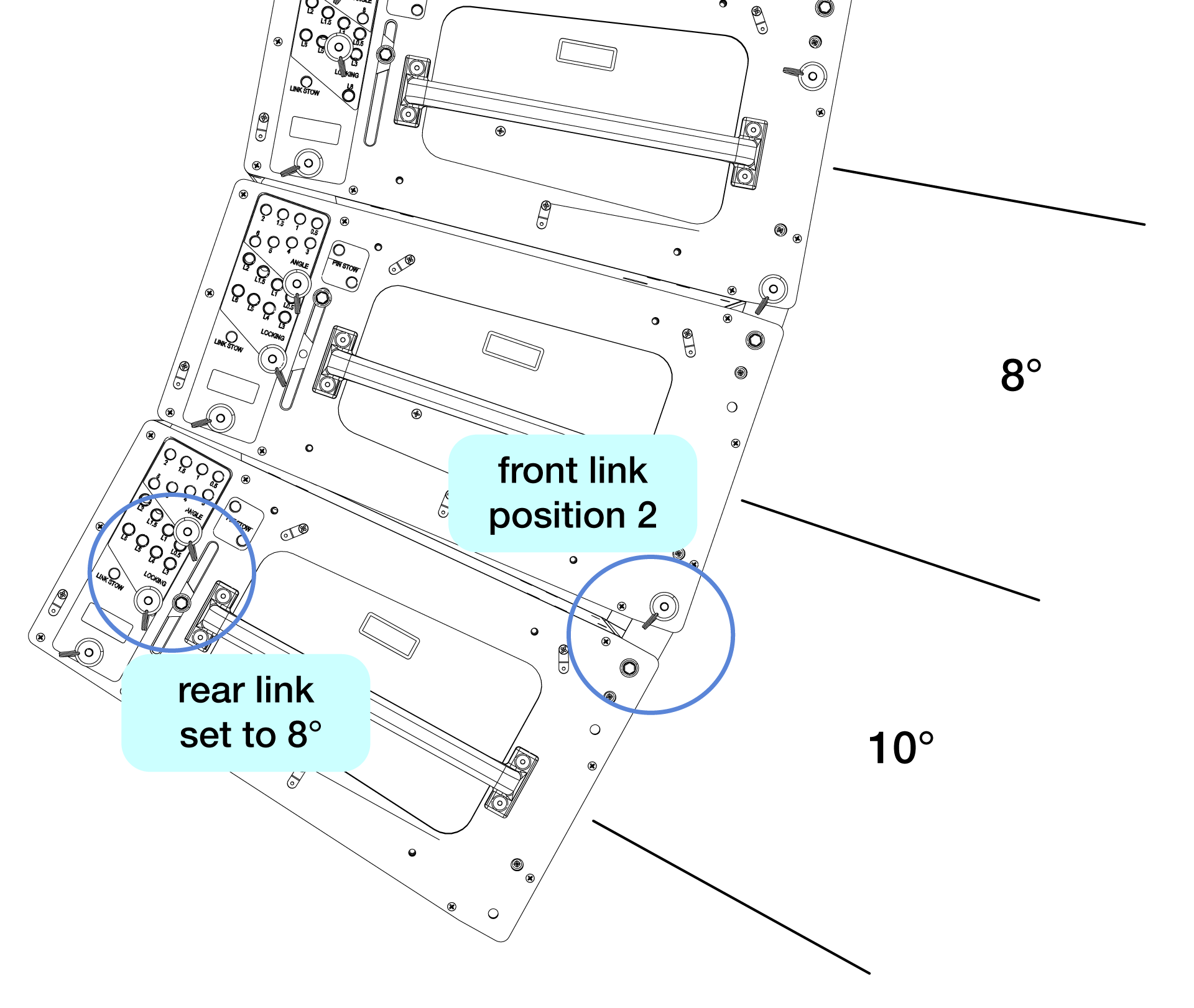
The front GuideALinks provide the rotation point between splayed TIGRA loudspeakers. Rear GuideALinks set cabinet splay except at 10°. For 0.5°–8° splay, secure the front link to the upper TIGRA in the 0 position. For 10° splay, secure the front link in the 2 position, adding 2° to the rear GuideALink 8° setting.
Rear GuideALinks
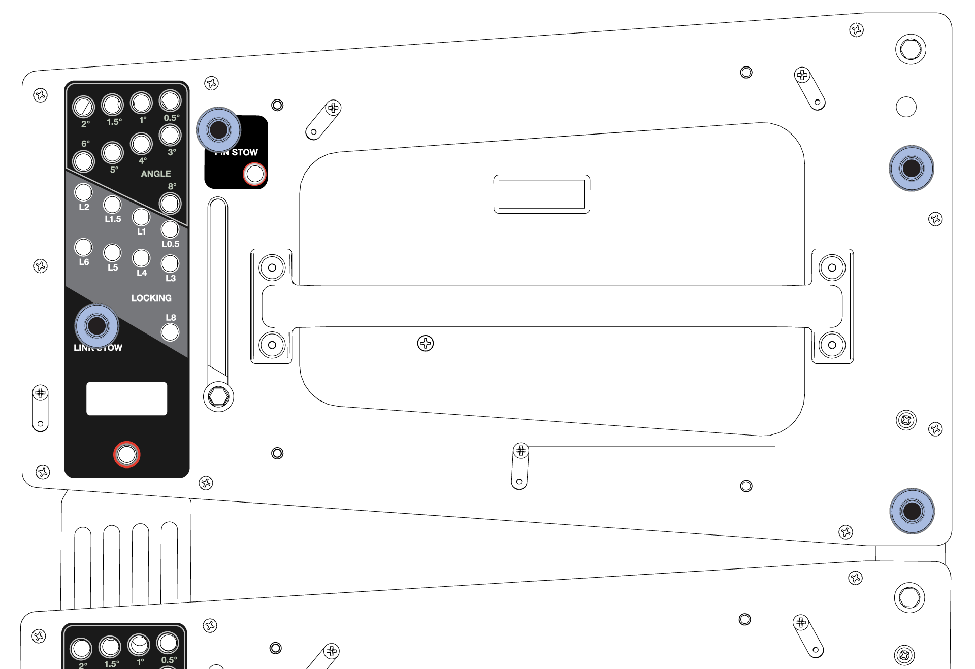
Rear GuideALinks set cabinet splay from 0.5°–8° relative to the cabinet above. Insert a quick-release pin on each side into the gray-on-black ANGLE hole; for example, a 5° rear GuideALink setting adds 5° downtilt relative to the cabinet above.
Each rear GuideALink includes eight ANGLE holes and eight LOCKING holes. While cabinets sit stacked on caster frames, insert pins into the selected ANGLE holes. When lifted, the GuideALinks extend to the selected splay angle; secure them with quick-release pins in the matching LOCKING holes.
Caution
Secure extended rear GuideALinks with at least one quick-release pin in an ANGLE, LOCKING, or LINK STOW hole. Never extend a link without a pin; otherwise, loudspeaker weight transfers to the non-load-bearing GuideALink knob.
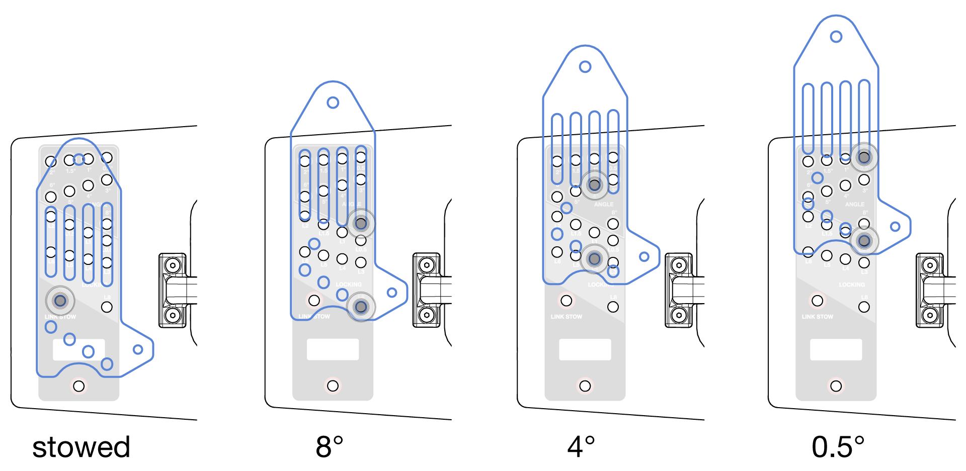
To achieve a 10° splay angle, set the rear link to 8° and the front link to the 2 position.
Quick-release pins
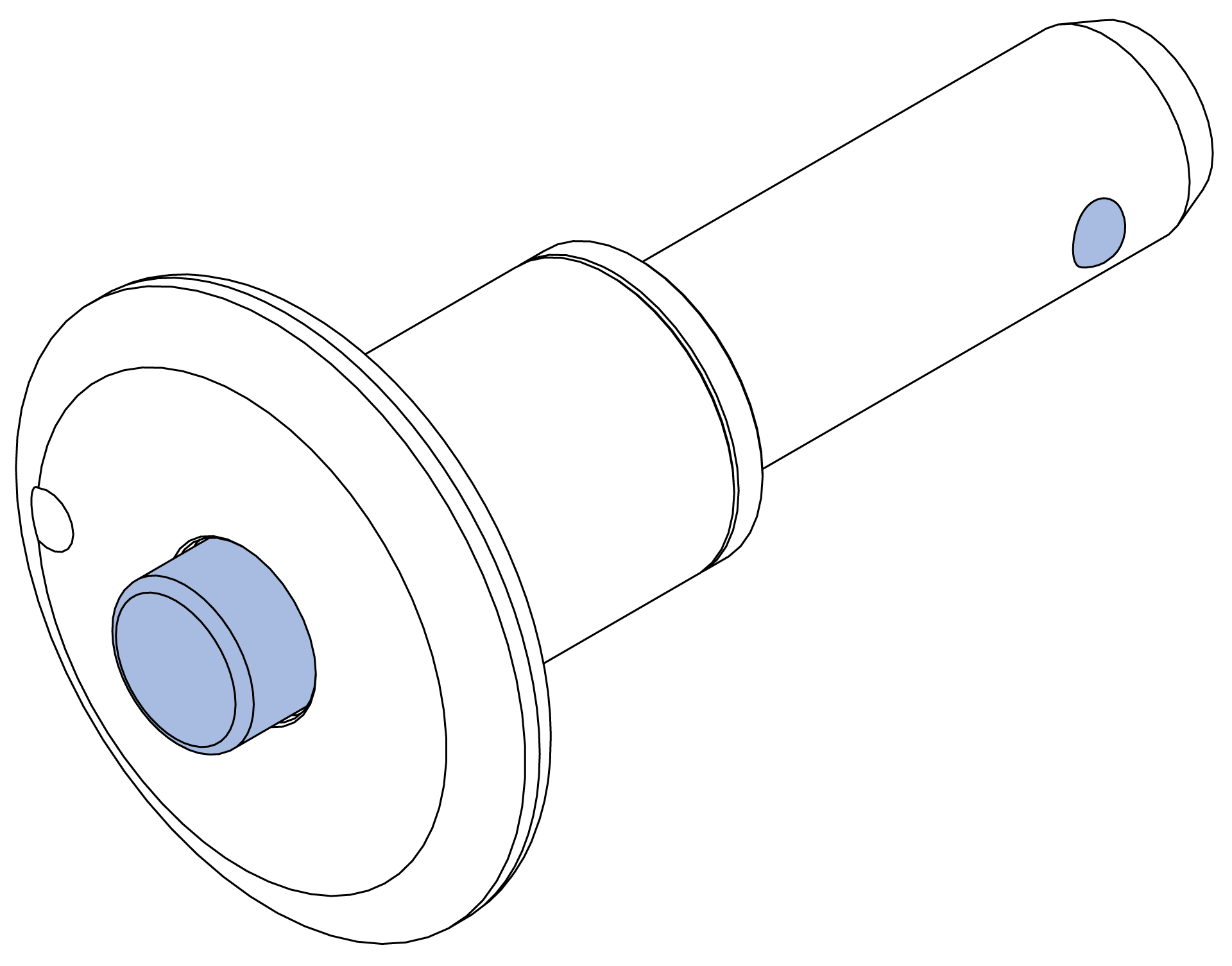
Quick-release pins lock after insertion. Press the head button while inserting or removing a pin; release the button to engage the lock. Verify full insertion and locking by pulling the pin away from the cabinet or rigging accessory without pressing the button.
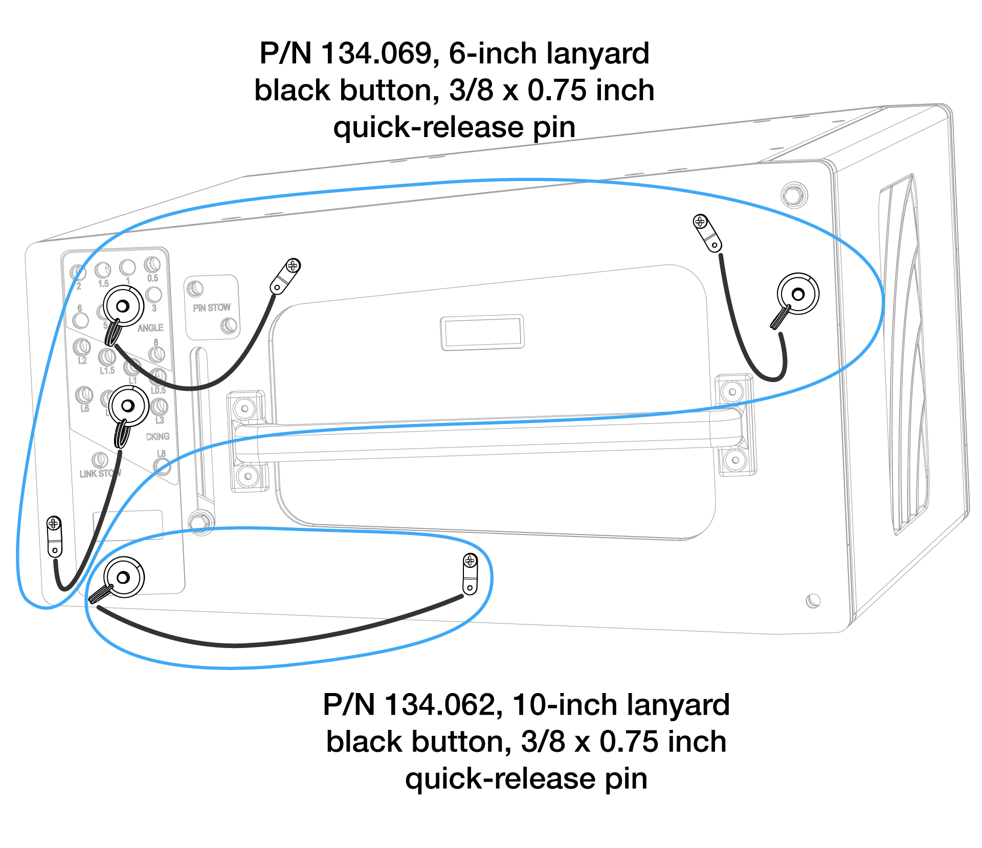
TIGRA ships with four lanyard-attached quick-release pins on each side. Move ANGLE, LOCKING, and lower pins only within the same cabinet. Use front pins on their attached cabinet and the cabinet above. Using rear pins in an adjacent cabinet may damage the lanyard when the array lifts and splay angles open.
Caution
Do not use any kind of tool to insert or remove quick-release pins. Adjust the height of the front or rear motor until the quick-release pin moves freely.
Do not strike a hard-to-insert quick-release pin with your palm; the locking balls may not release, causing hand injury.
The TIGRA QuickFly rigging system uses custom quick-release pins. For TIGRA arrays, secure GuideALinks and rigging accessories only with Meyer Sound quick-release pins; non-obvious custom features affect safety and performance.
Do not use damaged, deformed, or worn quick-release pins.
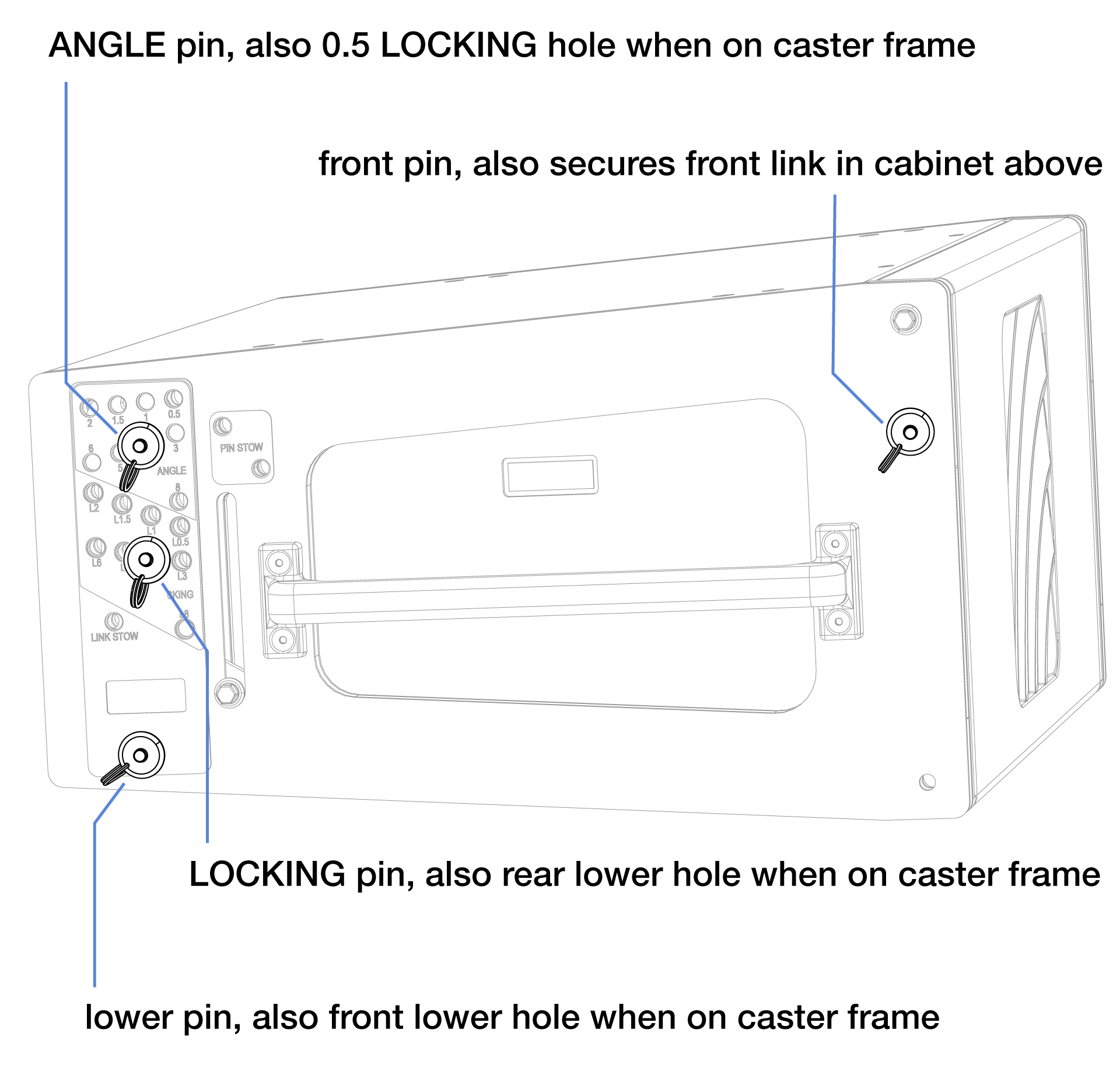
Each quick-release pin has a specific purpose.
·The ANGLE pin limits rear GuideALink extension but allows retraction to 8°, enabling preset angles with retracted links.
The LOCKING pin prevents GuideALink from extending or retracting.
The front quick-release pin retains the front GuideALink in the stow slot or secures it in the cabinet-above link slot; never use it with the grid box because of its short length.
The lower quick-release pin secures the top of the GuideALink from the cabinet below.
When securing a caster frame to an enclosure, move the ANGLE pin to the 0.5 LOCKING hole to secure the GuideALink; use the LOCKING pin for the cabinet rear and the lower pin for the cabinet front.
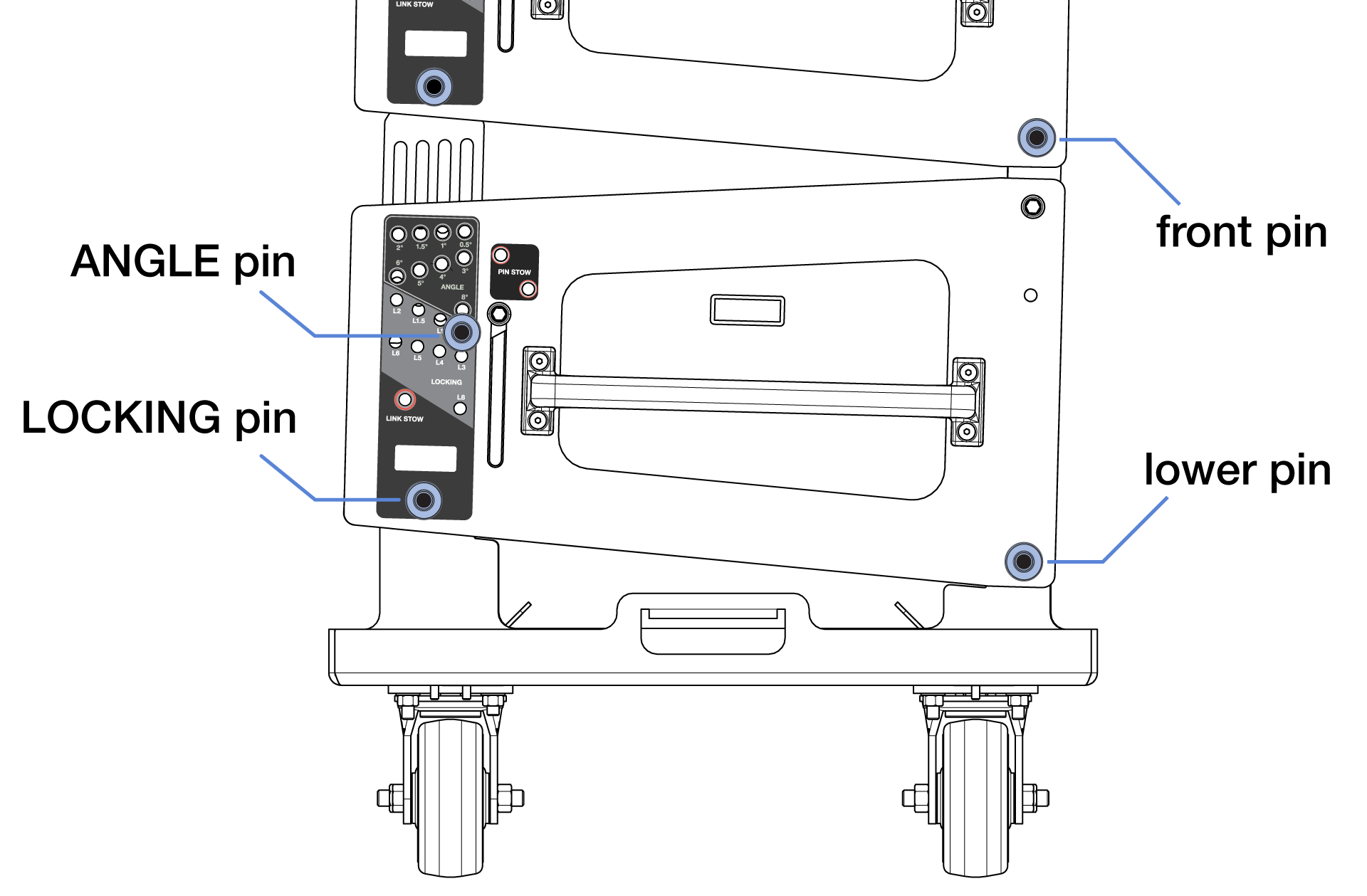
To retract and secure the rear GuideALink, move the ANGLE pin to a PIN STOW hole, remove the LOCKING pin, let the GuideALink retract, then move the LOCKING pin to the LINK STOW hole for transport. This rear-link configuration typically applies to the top cabinet in a caster-frame stack.
TIGRA rigging accessories
Model | Weight | Features | Required quick-release pins | Required shackles |
|---|---|---|---|---|
TIGRA Loudspeaker | 120 lb (54) kg) | 3/8 x 0.75-inch QRP (black button) with 6-inch lanyard (PN 134.069) qty 3 included 3/8 x 0.75-inch QRP (black button) with 10-inch lanyard (PN 134.062) qty 1 included | qty 1 included | (none required) |
MTG-T1 Top Grid Kit (PN 40.336.400.01) | 122 lb (55 kg) | Supports up to 16 TIGRA without splay angle limitations with a 5:1 safety factor. For up to 24 TIGRA, limited to 23-degrees of maximum uptilt, no Downtilt restriction, 5:1 safety factor:
Connects to top TIGRA of an array. Kit includes MGB-T1 Grid Box (PN 40.336.401.01) and MSB-T1 Shackle Bar (PN 40.336.402.01). | grid box 3/8 x 1.0-inch QRP (red button) with lanyard (PN 134.068) qty 4 included to connect to top TIGRA GuidALinks shackle bar 5/8 x 1.5-inch QRP (red button) with lanyard (PN 134.067) qty 2 included to connect to grid box | 5/8-inch for Shackle Bar connection to hoist(s) |
MBG-T1 Grid Box (PN 40.336.401.01) | 80 lb (36 kg) |
| 3/8 x 1.0-inch QRP (red button) with lanyard PN 134.068 qty 4 included to connect to top TIGRA GuidALinks | 5/8-inch for center points, 3/4-inch for corner points |
MSB-T1 Shackle Bar (PN 40.336.402.01) | 42 lb (19kg) | Attaches to MGB-T1 Grid Box, provides additional up/down tilt for array. | 5/8 x 1.5-inch QRP (red button) with lanyard PN 134.067 qty 2 included to connect Shackle Bar to Grid Box | 5/8-inch |
MPBF-T1 Pull Back Frame (PN 40.336.185.01) | 11 lb (5 kg) | For up to 12 TIGRA, 5:1 safety factor provided the MPBF-T1 is always lower in height than the grid box connected to the top of the array. For any number of cabinets, can support up to 1464 lb ( 664 kg) of array weight not supported by the grid box, 5:1 safety factor Pull-up (connection to shackle bar) not supported. Connects to the rear links of the bottom cabinet of TIGRA array. Provides additional array downtilt not achievable with the MTG-T1 Grid Kit alone. Pull-up (connection to shackle bar) configuration not supported. | This accessory is secured with the quick-release pins included with each TIGRA cabinet. | 5/8-inch, two locations |
MCF-T1 Caster Frame (PN 40.336.200.01) | 75 lb (34 kg) | Safely transports up to four TIGRA cabinets and the MG-TIGRA Grid Box (without the Shackle Bar), allowing assembly and disassembly of arrays in blocks of four cabinets. | This accessory is secured with the quick-release pins included with each TIGRA cabinet. | (none required) |
MTF-T1Transition Frame Kit (PN 40.336.140.01) | 71 lbs (32 kg) | Connects to the bottom cabinet of a PANTHER array to add TIGRA loudspeakers below. With some restrictions, up to six (6) TIGRA at any available splay angle, 5:1 safety factor. For rigging limitations, consider the added TIGRA as PANTHER cabinets and do not exceed the limits of a PANTHER array. | 5/8 x 1.5-inch QRP (red button) with lanyard PN 134.067 qty 4 included | 5/8-inch for pull-back tabs |
MVP Motor V Plate (PN 40.215.184.01) | 20 lb (9.1 kg) | Fine-tunes the horizontal aim of arrays; compatible with other Meyer Sound products. | N/A | 3/4-inch or 7/8- inch |
Caution
Use of any rigging replacement part not provided by Meyer Sound affects both safety and liability.
The TIGRA rigging system only supports a relative angle of 0 between the top TIGRA and the grid box.
Note
The accessories listed above ship with the required quick-release pins.
MCF-T1 caster frames do not include quick-release pins. Use TIGRA quick-release pins to attach the cabinet to the caster frame.
MBG-T1 Box Grid
The MBG-T1 Grid Box connects hoisting mechanisms to TIGRA cabinets. Two center shackle points, labeled A, measure 0.94 in (24 mm) and accept user-provided 5/8 or 3/4 in shackles. Four corner shackle points, labeled B, measure 1.13 in (29 mm) and accept user-provided 3/4 in shackles.
The grid box must either be suspended from:
both mounting points labeled A
-- OR --
all four mounting points labeled B
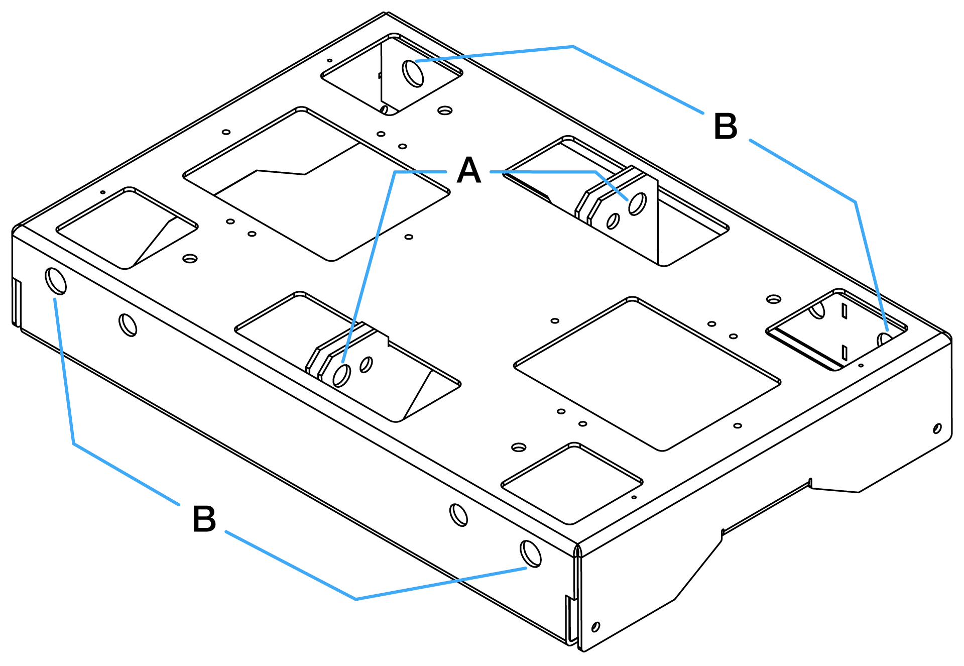
The center mounting points (A) are 16.25-inches (413 mm) apart.
The symmetrical MBG-T1 Grid Box has no front or rear and connects to a TIGRA loudspeaker in either orientation.
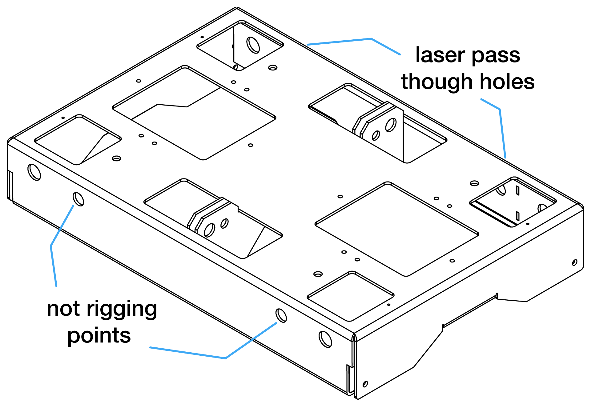
Top-plate accessory mounting holes support accessories up to 25 lb (11 kg) total.
When mounting an inclinometer under the top plate, use the four holes near the corner mounting points for laser beam clearance only; do not use them as rigging attachment points.
MSB-T1 Shackle Bar
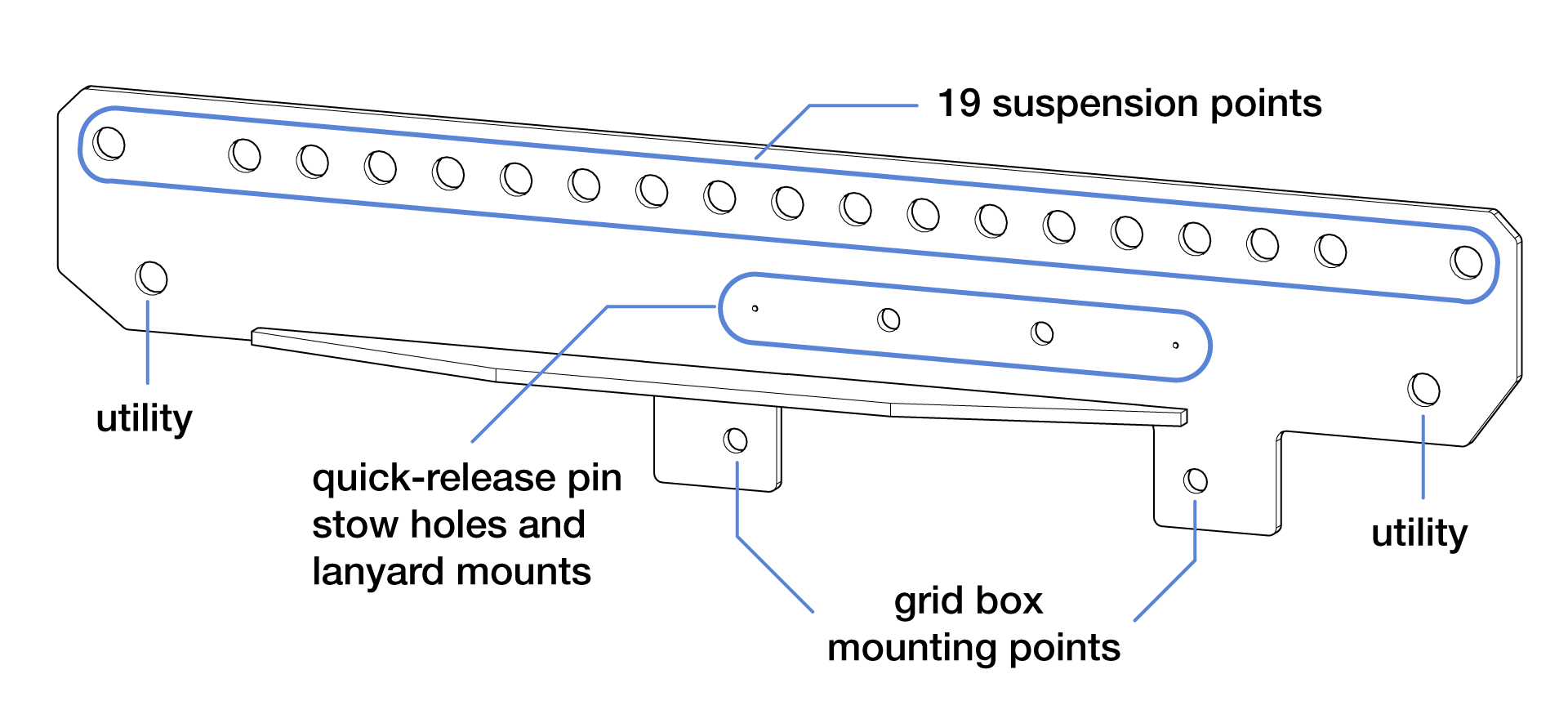
Secure the MSB-T1 Shackle Bar to the MBG-T1 Grid Box with the two red-button 5/8 × 1.5 in quick-release pins attached to the shackle bar to increase maximum array up/down tilt. Mount the shackle bar in either orientation to maximize up or down tilt. End mounting holes are 40 in (1 m) apart.
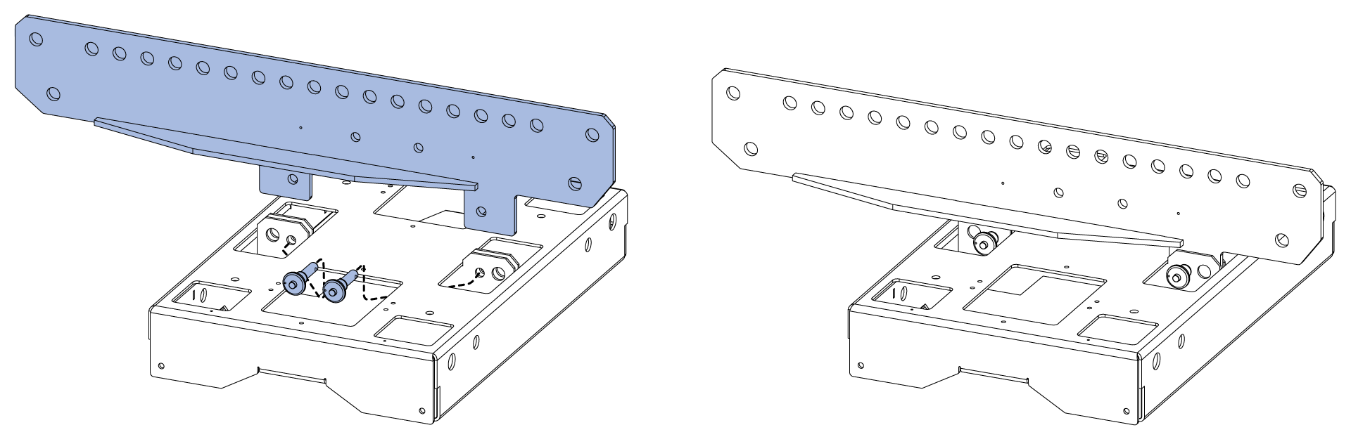
Suspend the shackle bar from one or two suspension points. For two-point suspension, connect hoists to the end holes to maximize uptilt or downtilt. Use utility holes for cable picks.
User-provided equipment
Depending on application needs, consider:
Motorized hoists
Rated rigging hardware, such as shackles, wire rope, and pear rings
Inclinometer
Tape measure
Laser distance meter
Load cells for measuring rigging loads
For inverted chain motors, motor down, add a short wire rope or deck chain between Meyer suspension hardware and the motor hook to allow proper take-up chain collection and keep the front chain bag from blocking the top-cabinet high-frequency output.
For bridles between MG-PANTHER Shackle Bar points, the bridle apex must be 90° or less.
Include all suspended items, such as downfill loudspeakers, pull-back accessories, transition accessories, and cable, when calculating suspended weight.
For two-hoist arrays, one hoist may support the full array weight during assembly; use hoists, wire rope, shackles, and other rigging hardware rated for the maximum possible load.
Prepare to assemble a TIGRA array
Use acoustic predictions provided by Meyer Sound’s MAPP 3D system design and prediction software to determine the optimum array position, number of TIGRA loudspeakers required, which models provide the coverage desired, the shackle bar orientation, the trim height, grid box angle, and the splay angles between cabinets.
From the MAPP design, document the following array information:
Trim height
Grid rotation angle
MG-PANTHER shackle bar orientation (forward/max downtilt or rearward/max uptilt)
If suspending from a single point, document the attachment point of the MG-PANTHER shackle bar to connect the hoist to
Splay angles of TIGRA cabinets
Locations in the array of TIGRA models
Front and rear rigging weights
Total array weight
Drive lines, Galileo GALAXY output channels
In some regions, regulations require dead-hanging of all suspended loads, bypassing the loading of all movable hoists. A dead-hang uses a wire rope or chain to carry the suspended load, removing the entire load from the hoisting mechanism(s) used to raise and lower the array. Ensure the proper rigging equipment is available when needed
Assemble a TIGRA array
Warning
BEFORE ASSEMBLING ARRAYS, REVIEW THE Safety statement for rigging.
The following assembly steps assume TIGRA cabinets stacked on caster frames, each GuideALink connected to the TIGRA above, and the grid box disconnected from the top cabinet. Portable caster-frame arrays require front and rear motors; small motor bumps may relieve quick-release pin tension or compression.
For installations or single-point suspension, position each TIGRA below the rigging points and add cabinets to the array one at a time. For assistance, visit meyersound.com/contact and submit a support case.
Important
Because the sides of the TIGRA cabinets are symmetrical, when the steps below give instructions related to one side of a cabinet, always duplicate the action on the other side of the cabinet. The duplicate instructions for the other side of the cabinet are not included.
For readability of the following steps, quick-release pin is shortened to pin, and GuideALink is shortened to link.
To assemble a TIGRA array:
Step 1: Prepare TIGRA cabinets
Remove protective covers from TIGRA stacks and arrange stacks in array order.
Retract all links on each stack’s top cabinet. Landing a grid box or cabinet on ground-supported cabinets with extended links can damage the end frames or links if alignment is not perfect.
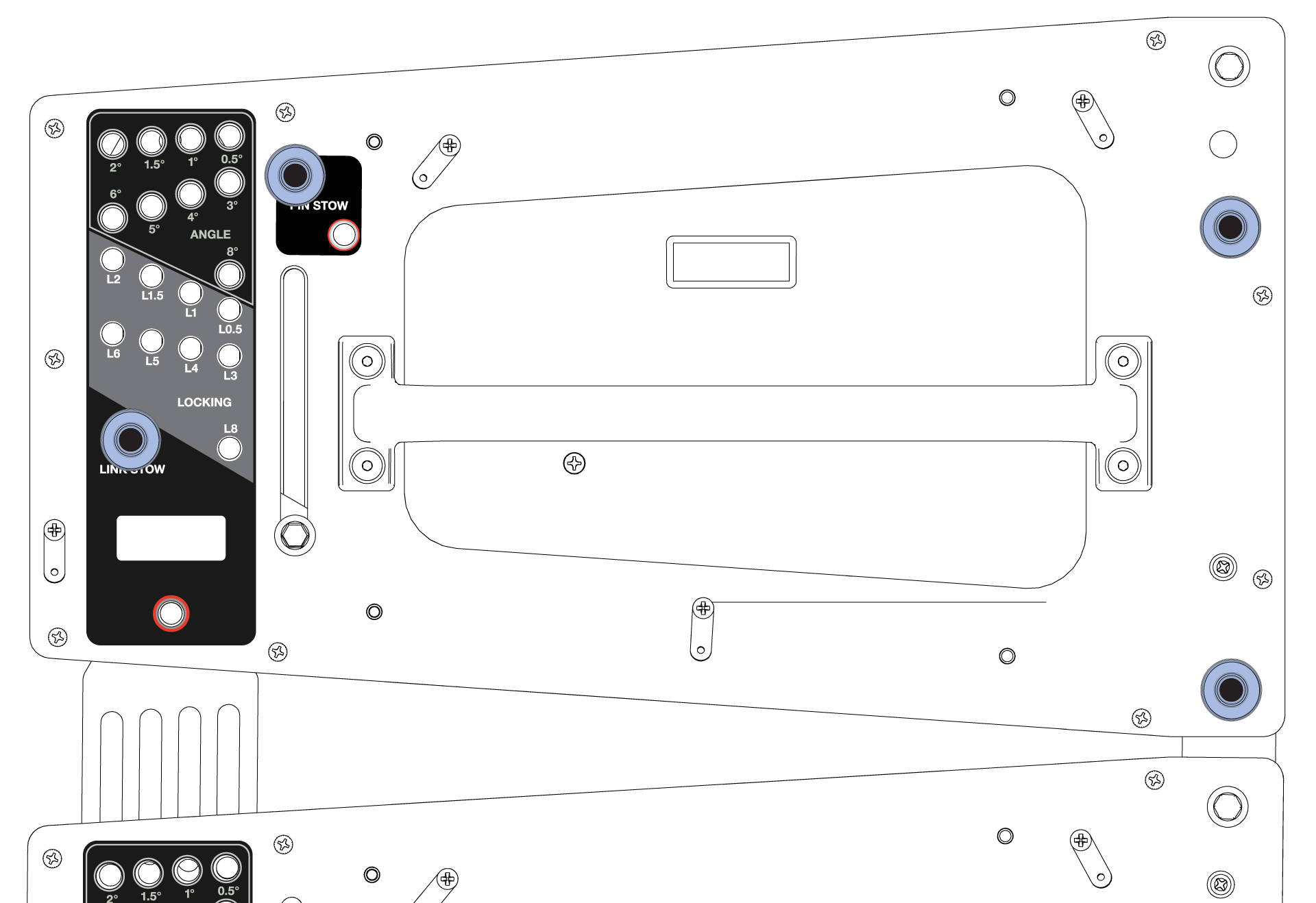
Step 2: Suspend the grid box or top grid kit
If called for in the array design, secure the shackle bar to the grid box with the two 5/8 x 1.5-inch (red button) pins attached to the shackle bar. Connect the hoists to the shackle bar or grid box.
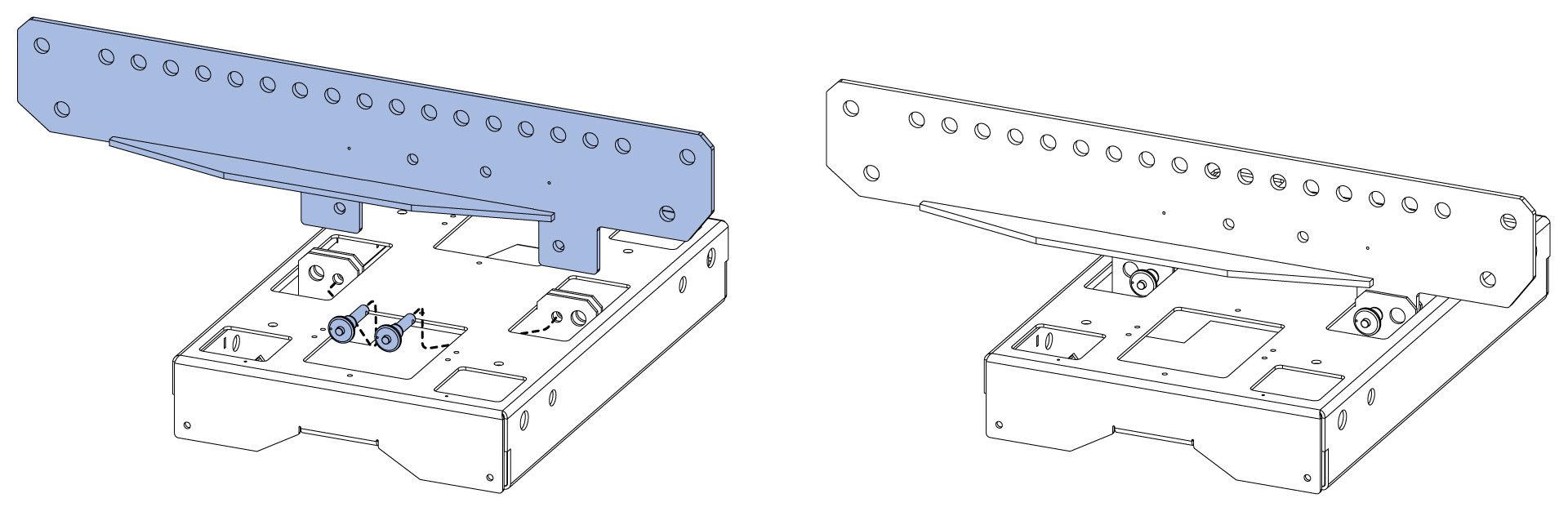
Securely mount any accessories to the shackle bar or grid box - lasers, inclinometers, tape measure, cable pick, etc.
Roll a stack of TIGRA under the grid box, then lower the grid box until it is within 2-inches (5 cm) of the TIGRA enclosure.
On the side of the grid box, remove the rear red-button pin.
Remove the LOCKING pin from the LINK STOW hole and put it in a PIN STOW hole.
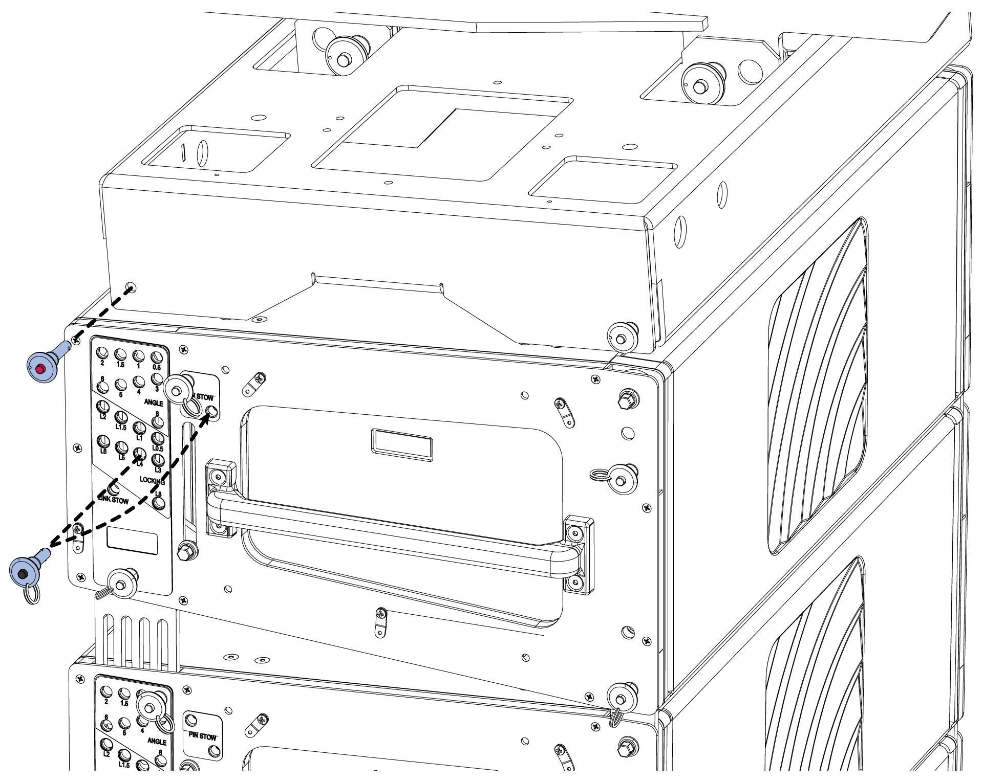
Grasp the hex link knob and raise the rear link of the TIGRA into the link socket of the grid box. Secure the link with the red-button pin that is attached to the grid box.
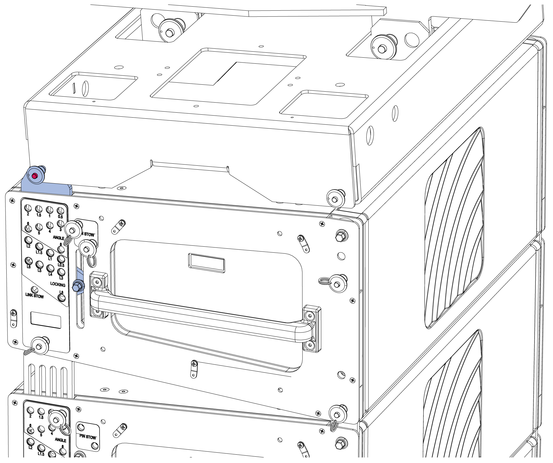
Remove the front red pin from the grid box.
Remove the front link pin and rotate it into the grid box link socket. Replace the front link pin.
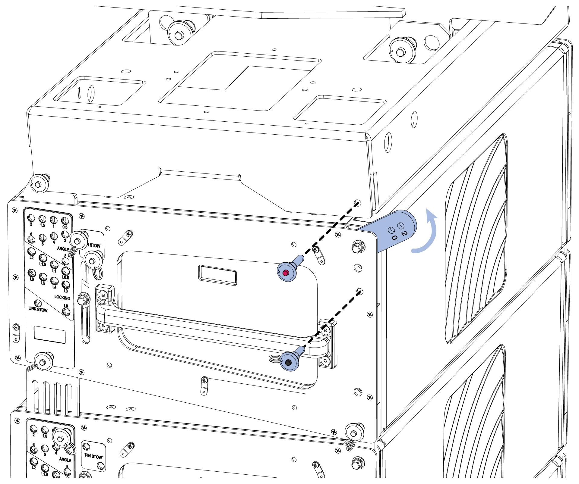
Adjust the front hoist as needed to secure the front link in position 0 with the red-button pin that’s attached to the grid box.
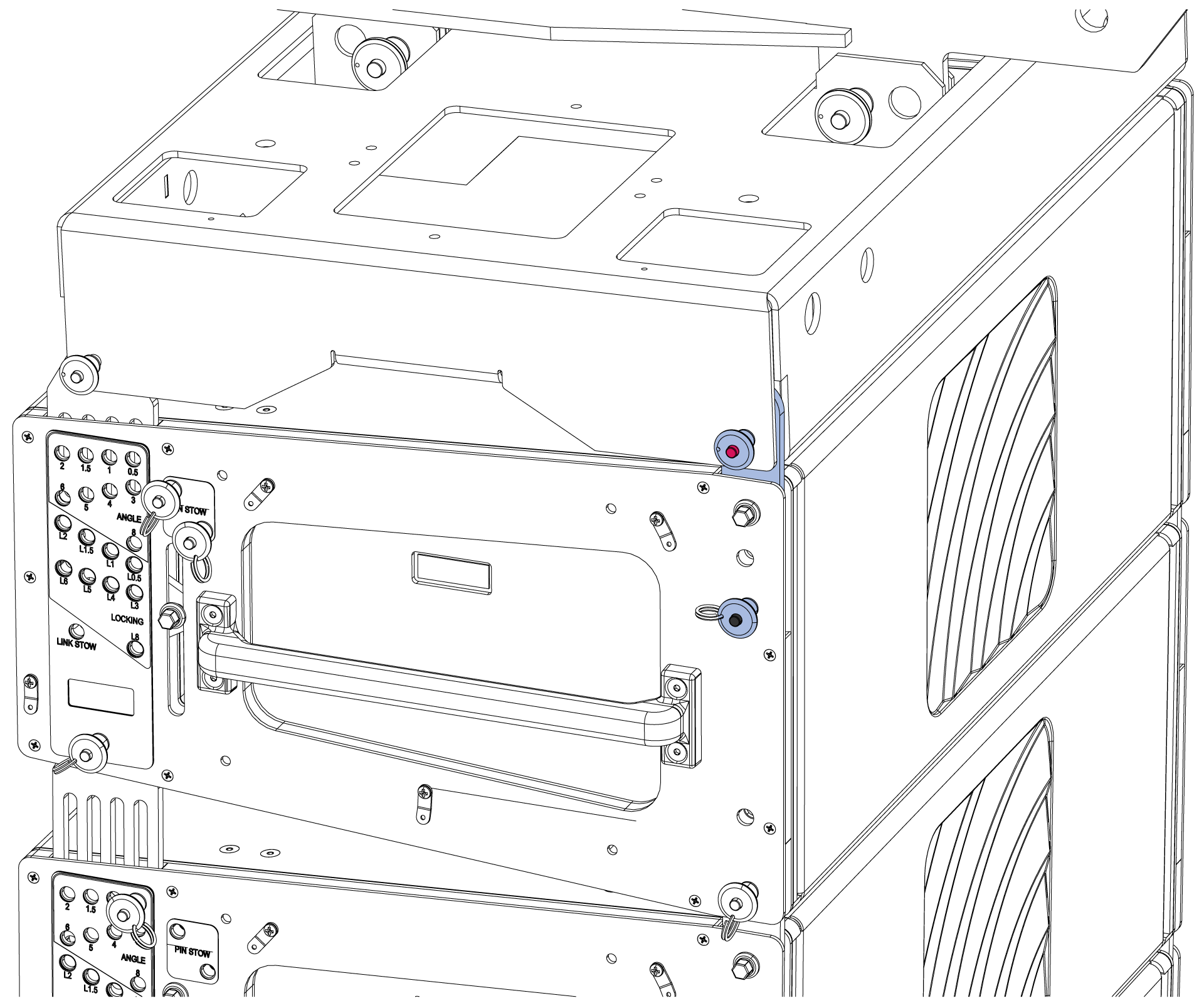
At the rear of the endframe, move the ANGLE pin to the 4° position.
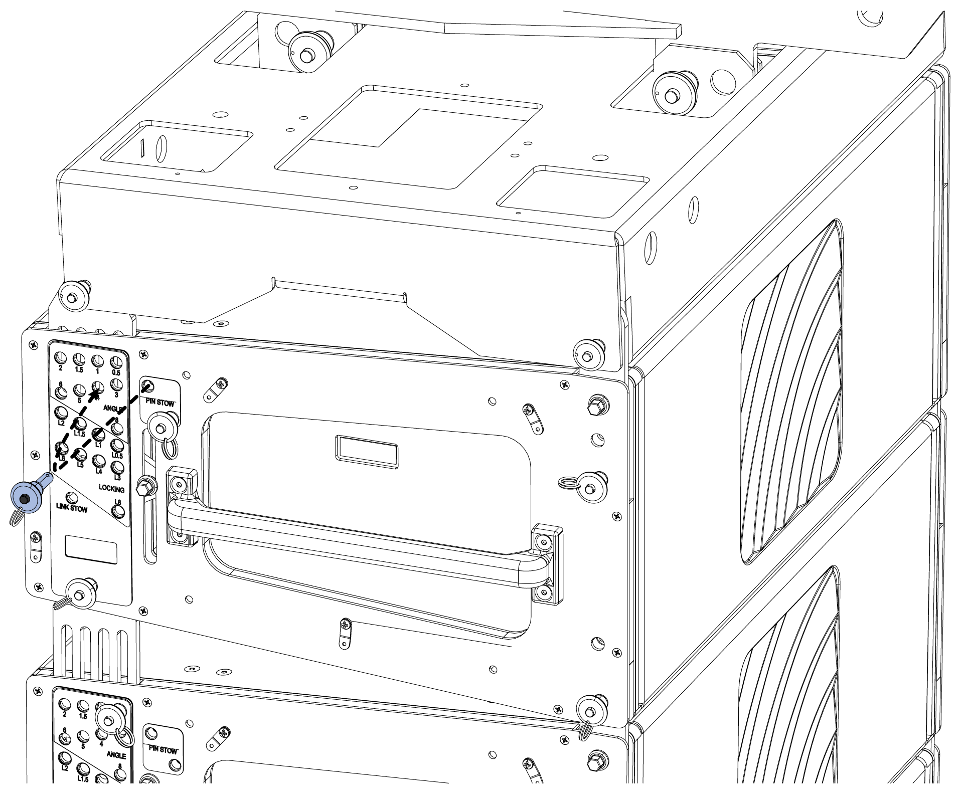
Raise the rear hoist until the rear link stops extending. Move the LOCKING pin to the 4° hole.
The top TIGRA is now connected to the grid box and the center lines are parallel.
This rigging system does not support any other relative angle between the top TIGRA and the grid box other than zero degrees.
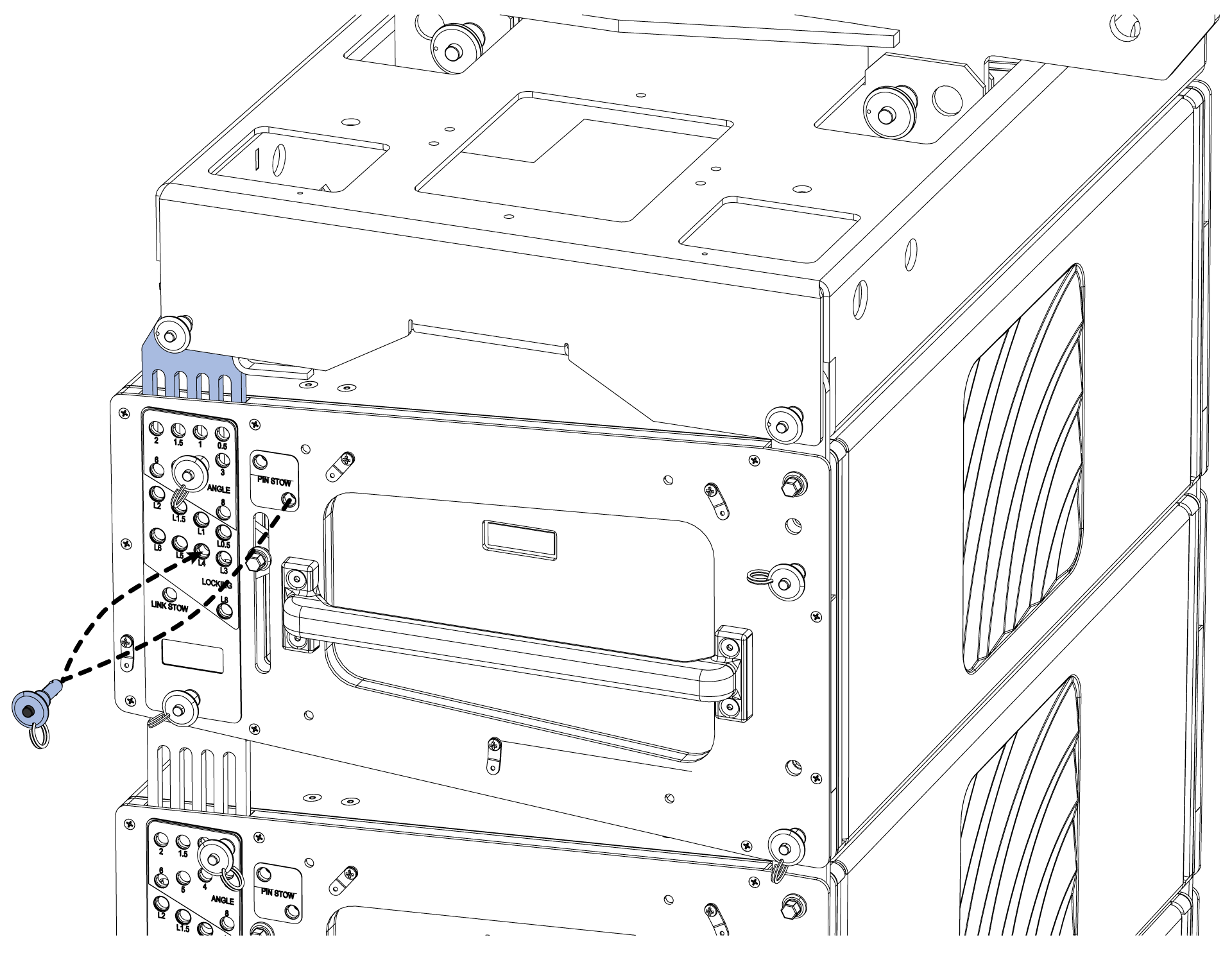
Step 3: Set splay angles
TIGRA 2-3, move the LOCKING pins to the PIN STOW holes.
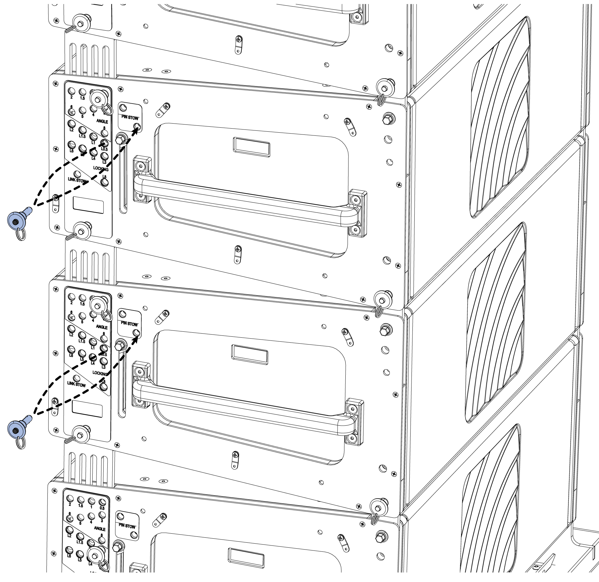
TIGRA 4, move the LOCKING and ANGLE pins to PIN STOW holes – adjust the rear hoist as needed.
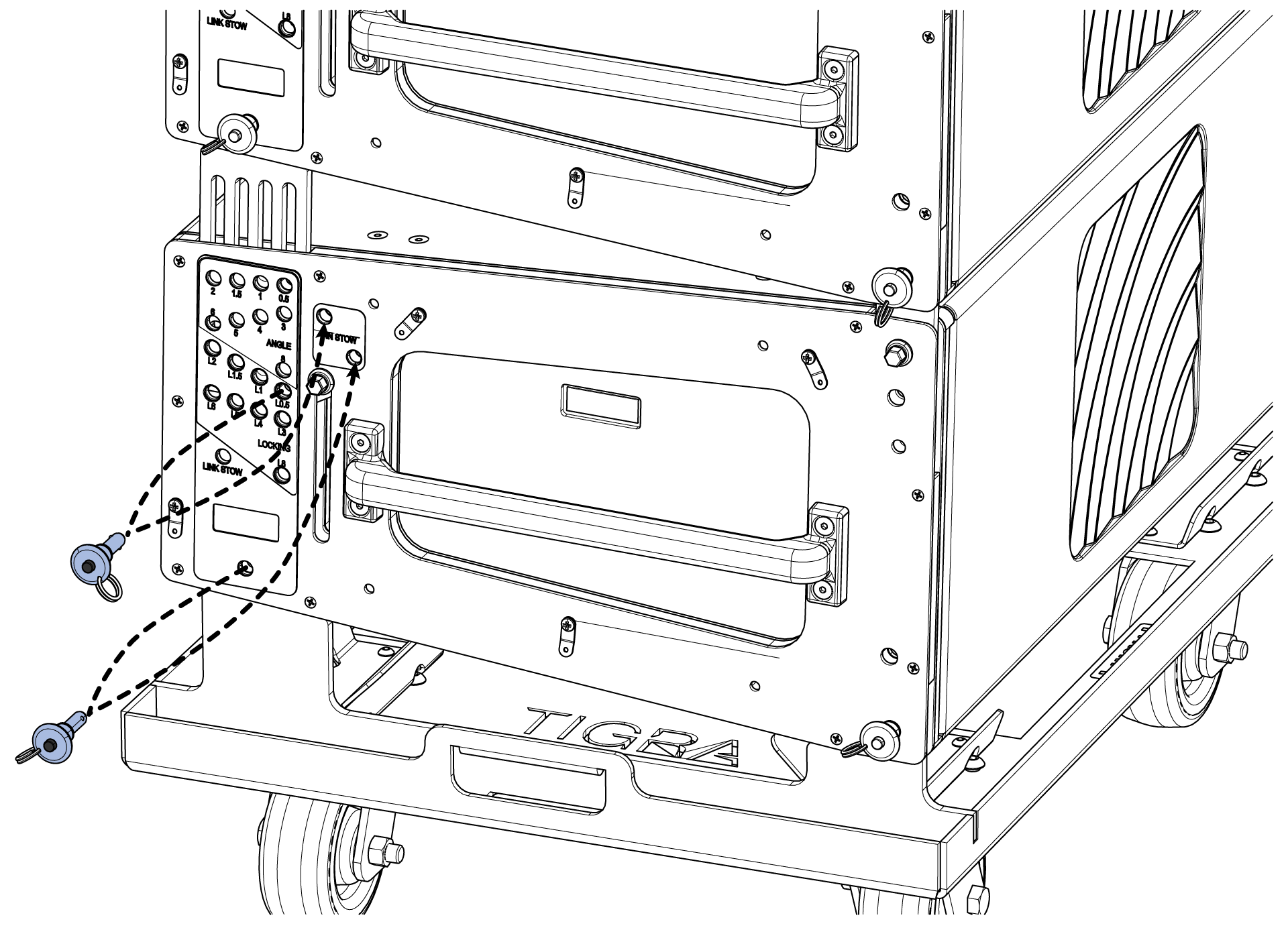
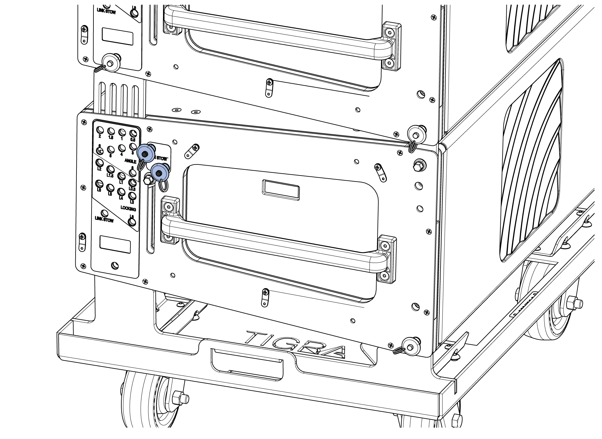
Lower the rear motor until all the rear links are completely retracted and move TIGRA 2-4 ANGLE pins to the ANGLE holes that correspond with array design.
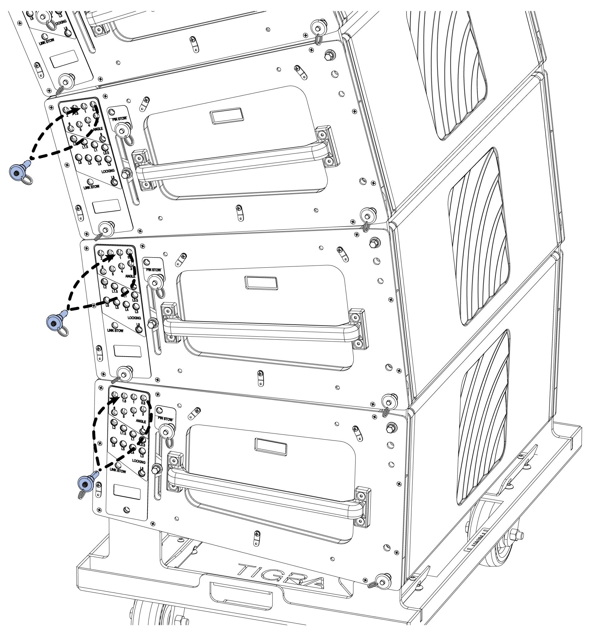
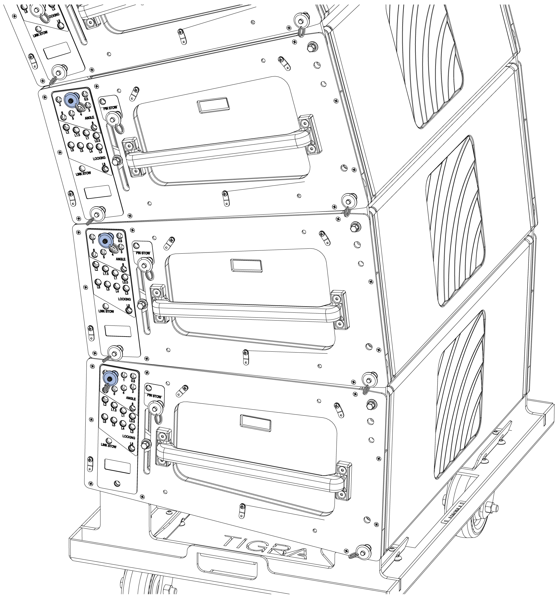
Raise the rear motor until all the rear links are extended. Move TIGRA 2-4 LOCKING pins from the PIN STOW hole to the LOCKING hole that correspond with each ANGLE pin.
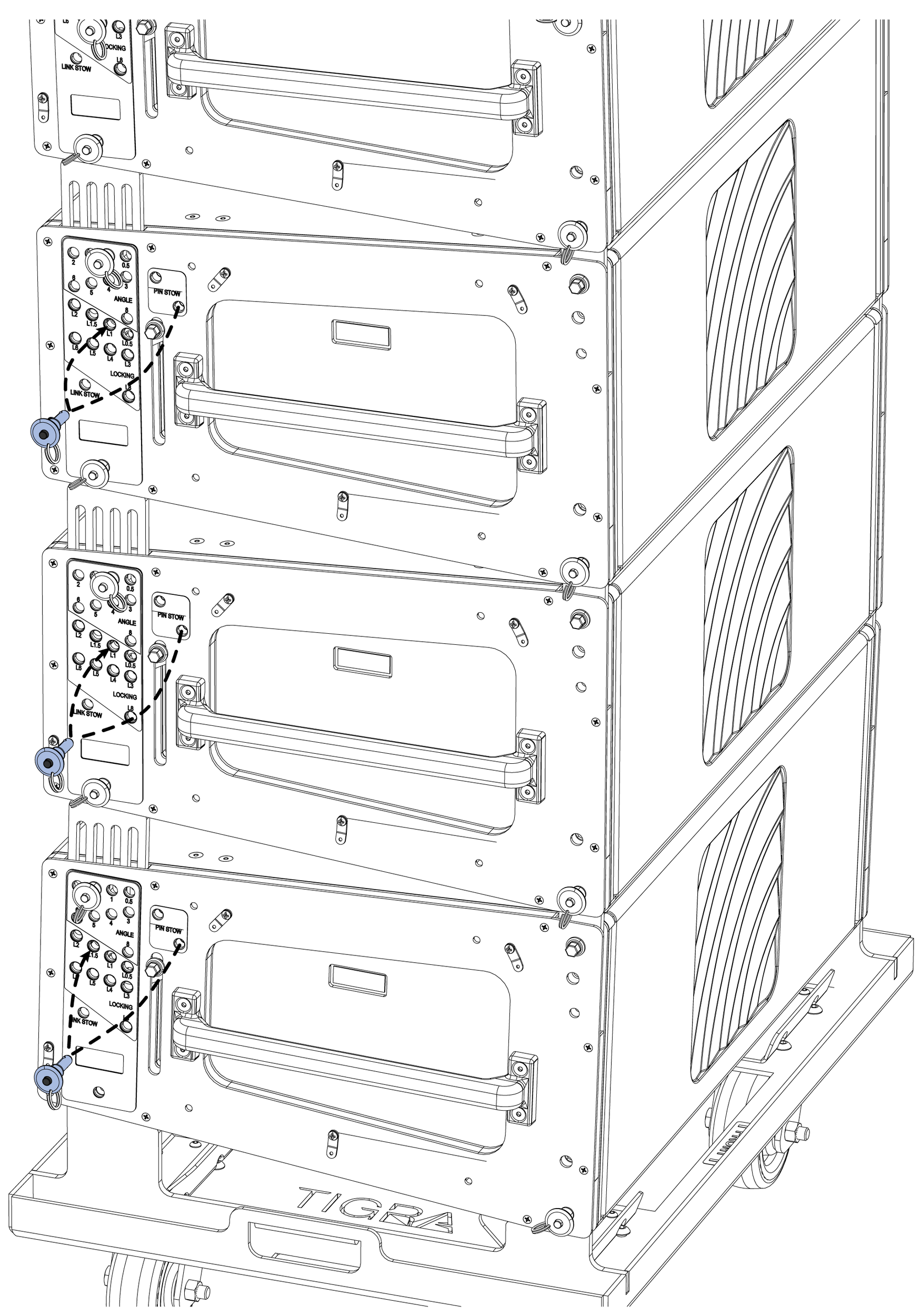
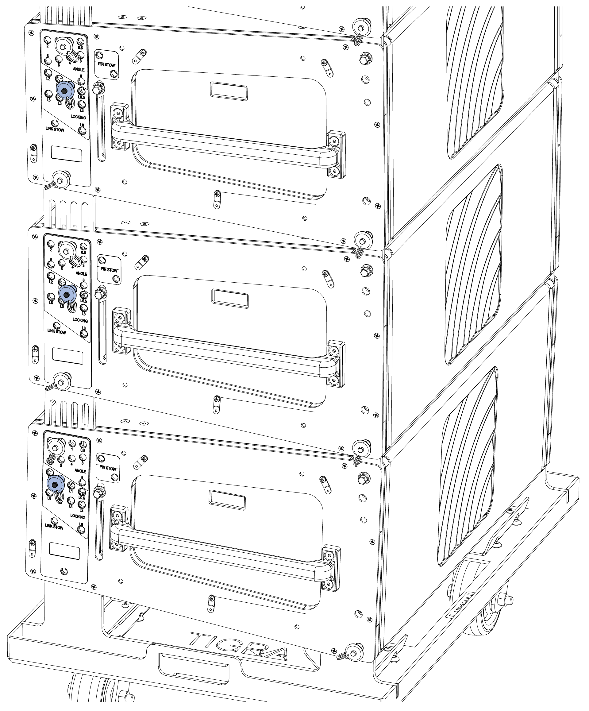
Step 4: Remove the caster frame
Remove the lower pin, raise both motors slightly, and move the pin to the rear, lower hole.
Move the caster frame to a nearby location. Additional caster frames will be stacked on this one.
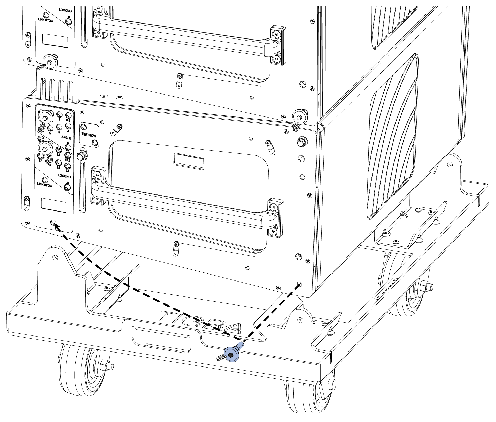
Visually confirm the pins are in the correct locations on both sides of the array.
Attach the cable pick to the utility hole on the shackle bar and make all power, signal and network connections.
Step 5: Add another stack of cabinets
Roll the next stack of TIGRA under the flown cabinets and lower the flown cabinets until they are within 2-inches (5 cm) of the top stacked cabinets.
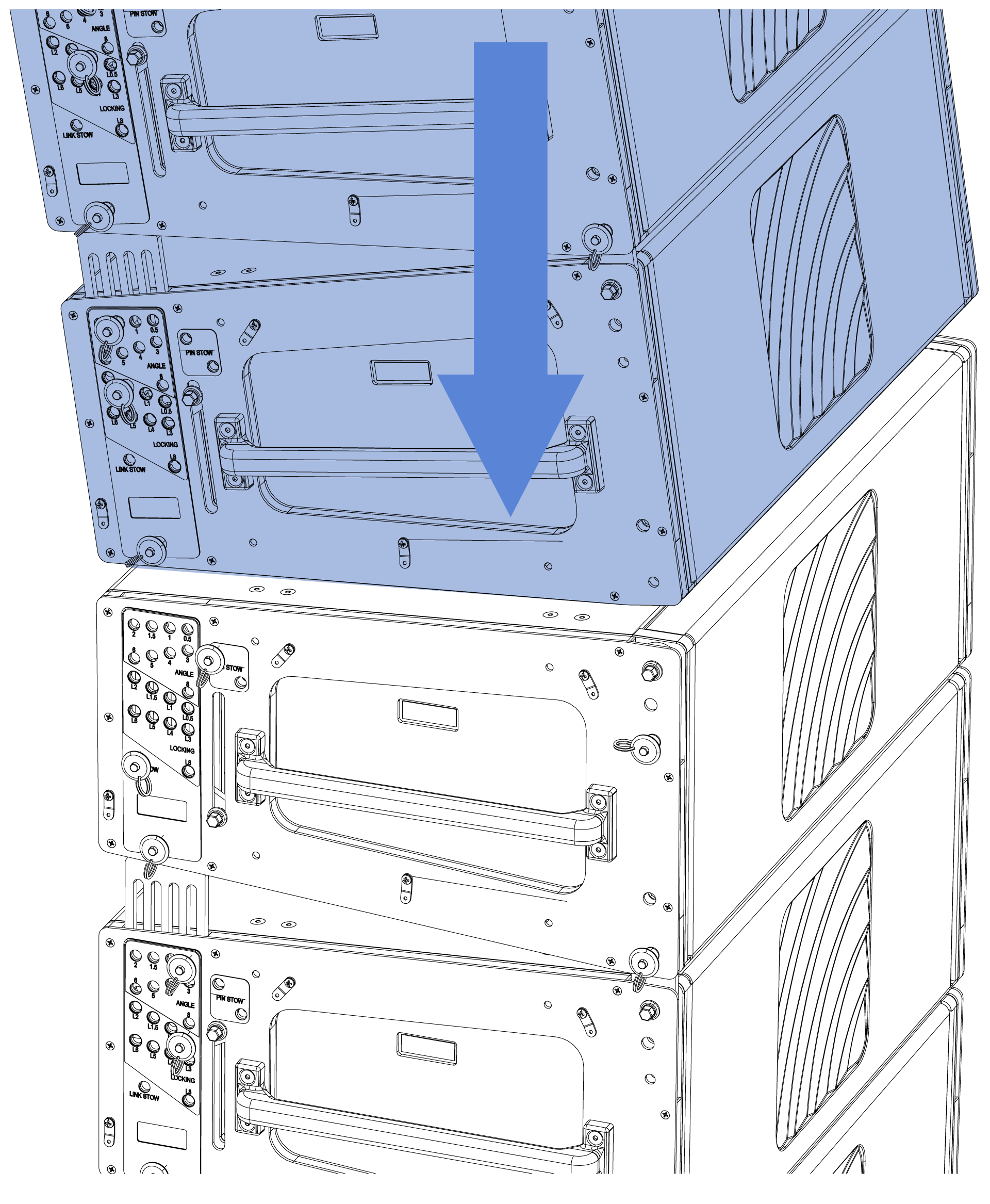
For the top cabinet of the stack, move the LOCKING pin from the LINK STOW hole to the PIN STOW hole.
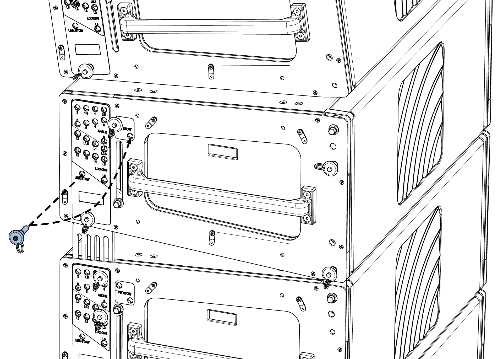
Remove the lower pin from the suspended cabinet, raise the link knob of the stacked cabinet extending the link into the link socket of the suspended cabinet, and secure it with the lower pin.
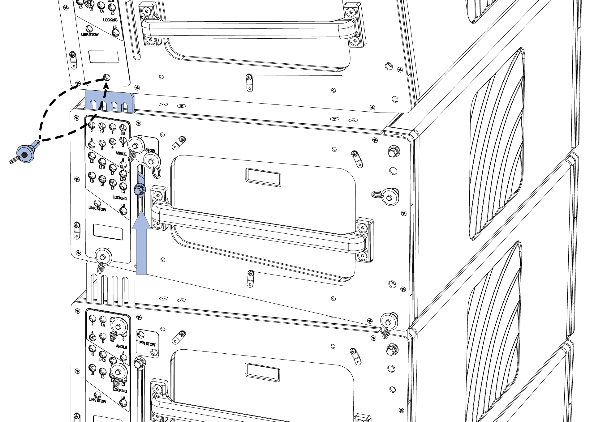
Move the ANGLE pin of the first stacked cabinet to the ANGLE hole that matches the array design - lower the rear hoist if needed.
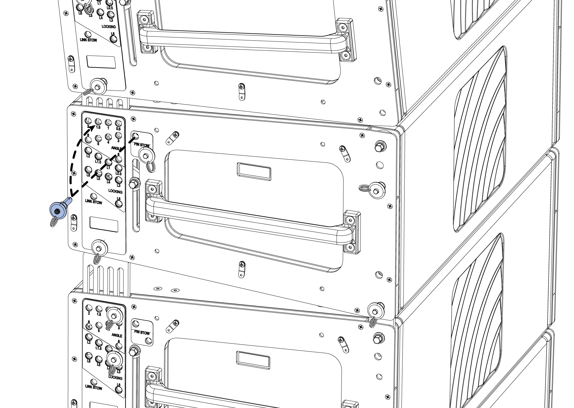
Remove the front pin and rotate the front link into the link socket of the suspended cabinet. Adjust the front hoist as needed to secure the link with the front pin. Reference the array design for the front link position, 0 or 2.
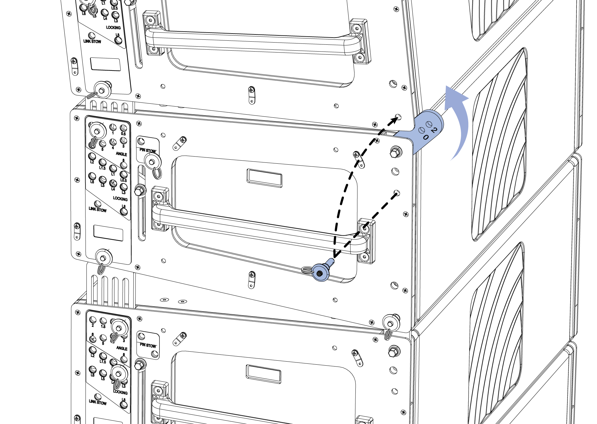
Repeat the Set splay angles and Remove caster board steps for the second stack of cabinets.
Add more TIGRA stacks the same way: repeat Add another stack of cabinets, Set splay angles, and Remove caster board.
After assembly, raise the array to trim height and adjust the grid angle to match the array design.
Stack caster frames for storage. Before stacking, tip the caster frame until all wheels face the same direction, then lower one end onto the frame below, followed by the other end.
Prepare to disassemble a TIGRA array
Complete the following before disassembling the array:
De-energize the electrical system providing power to the loudspeakers.
Disconnect cabling connected to equipment on the ground.
Disconnect any rigging hardware used to secure the horizontal aim of the array.
If the array is dead hung (required in some regions), raise the hoists so they take weight and remove the rigging hardware associated with the dead hang.
Disassemble a TIGRA array
Important
Before lowering the array, make sure that attached cabling has enough slack and that the area around and under the array is clear of obstructions.
Because the sides of the TIGRA cabinets are symmetrical, when the steps below give instructions related to one side of a cabinet, always duplicate the action on the other side of the cabinet. The duplicate instructions for the other side of the cabinet are not included.
When using two hoists, lower the hoist carrying the greater weight to approximately equalize the weight carried by each hoist.
Lower the array to within 3 ft (1 m) of the working surface and tip the array up, making the bottom cabinet more parallel with the working surface.
Lower the array until the bottom cabinet is 1 to 2 inches (2.5 to 5 cm) above the height of an MCF-PANTHER Caster Frame and move an MCF-PANTHER under the cabinets.
Connect an MCF-T1 Caster Frame to the bottom of the array.
Lower the array until either the front or rear caster frame wheels contact the working surface.
Disconnect all cabling from the cabinets to be removed from the array.
Remove the quick-release pins in the white-on-gray LOCKING holes of the cabinets to be disconnected from the array.
Note
Small adjustments of the hoists may be necessary to relieve tension or compression of the front GuideALinks.
Raise the rear of the array until the rear links are completely extended.
Insert the LOCKING pins in the 0.5° hole.
Remove the quick-release pin securing the rear link of the top cabinet to be disconnected from the array.
Raise the hoists until the quick-release pin securing the front GuideALink can easily be removed.
Prepare the stack to be transported.
Note
The quick-release pins can be in any of the gray-on-black ANGLE holes.
Caution
When TIGRA loudspeakers are stacked on the caster frame, the splay angles should all be 0.5°. The rear links of each cabinet should be extended and secured in place with quick-release pins connecting each cabinet of the stack to one another. For stacks that do not include the grid box, retract the GuideALinks of the top cabinet.
Move the stack of cabinets from under the suspended array.
Open the flap of the 4-high cover and slide over the top of the stacked cabinets.
Repeat steps 5-12 for additional stacks of cabinets.
PN: 05.336.005.01 B 2607 |