MM-10XP Subwoofer
The MM-10XP is powered by an external 48 V DC power supply (see meyersound.com/product/mps for details), eliminating the need for wiring conduits while still preserving the advantages of self-powered loudspeaker systems. The unit's onboard amplifier and signal-processing circuits were designed to store DC power and tolerate voltage drops, thereby accommodating light-gauge cables and lengthy cable runs.
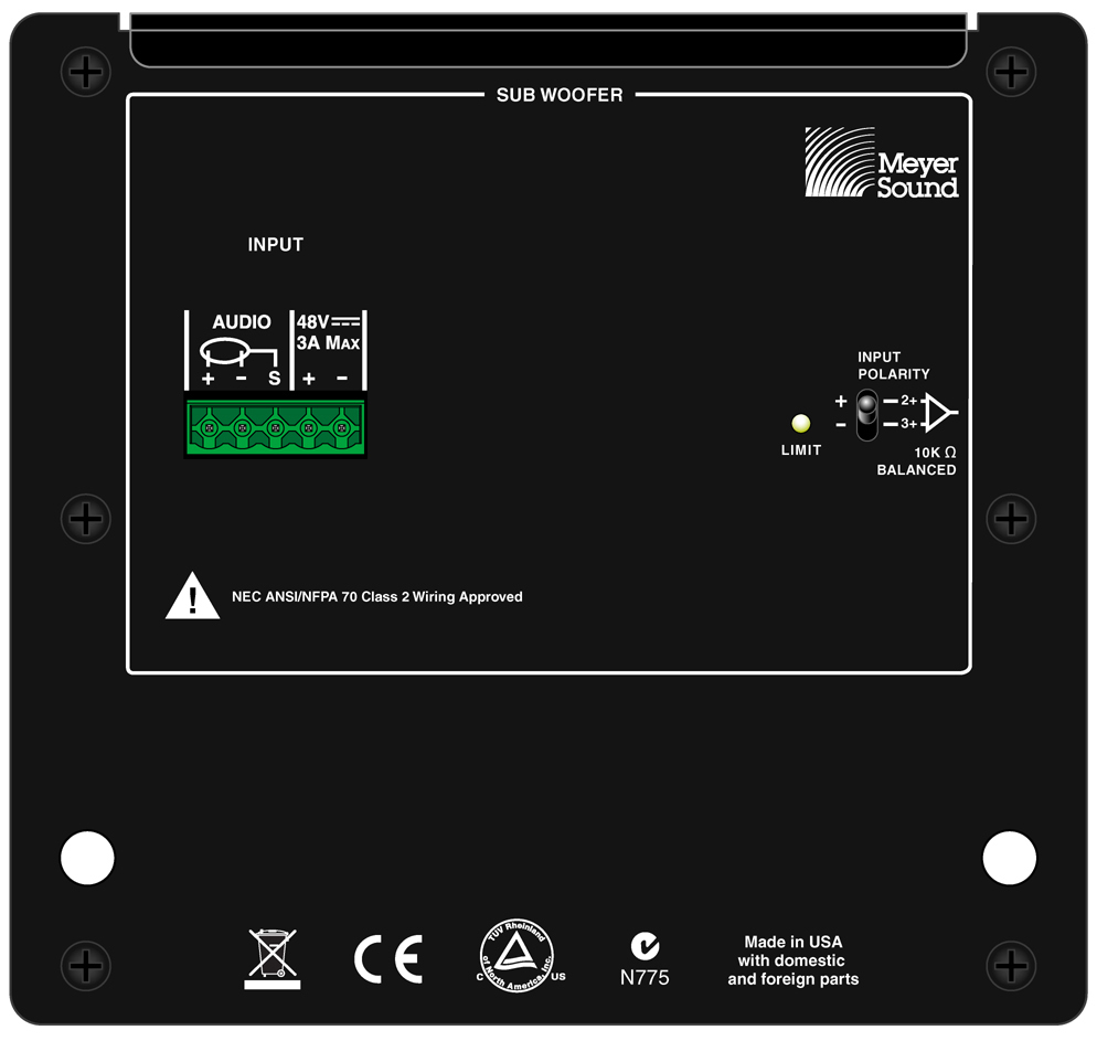 |
MM-10XP Rear Panel, Phoenix Connector
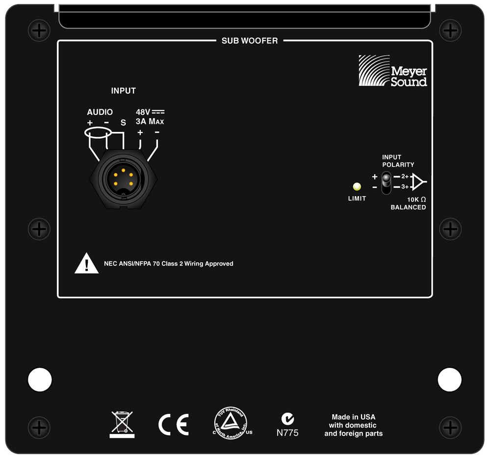 |
MM-10XP Rear Panel, EN3 Connector
MM-10XP Input Connector
The MM-10XP is powered by a Meyer Sound external 48 V DC power supply, eliminating the need for wiring conduits while still preserving the advantages of self-powered loudspeaker systems. The unit's onboard amplifier and signal-processing circuits were designed to store DC power and tolerate voltage drops, thereby accommodating light-gauge cables and lengthy cable runs.
The MM-10XP subwoofer is available with either a Phoenix 5-pin male or SwitchCraft EN3 5-pin male connector for receiving DC power and balanced audio. The connectors’ five pins include two for DC power (negative and positive) and three for balanced audio (shield, negative, and positive). These pins are clearly labeled on the MM-10XP rear panel. To function properly, the MM-10XP requires 48 V of DC power.
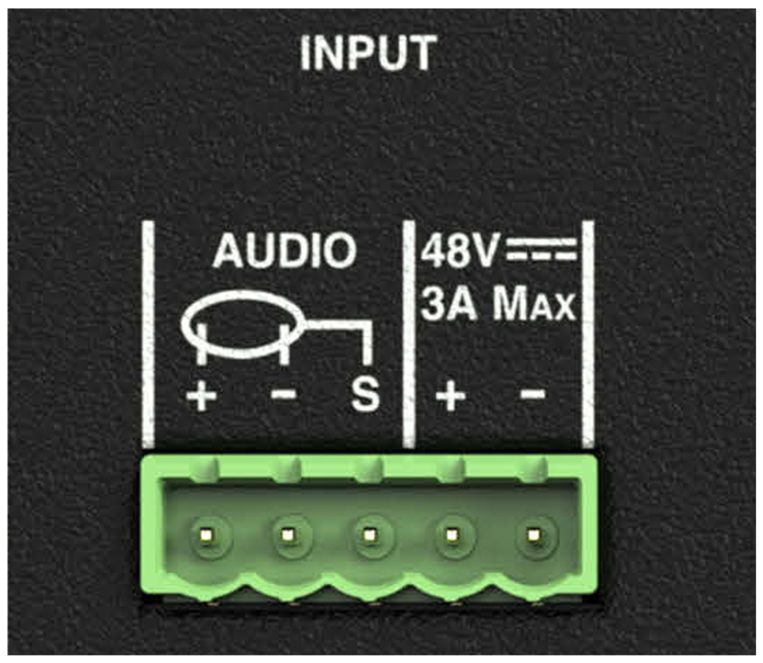 |
Phoenix 5-Pin Male Connector
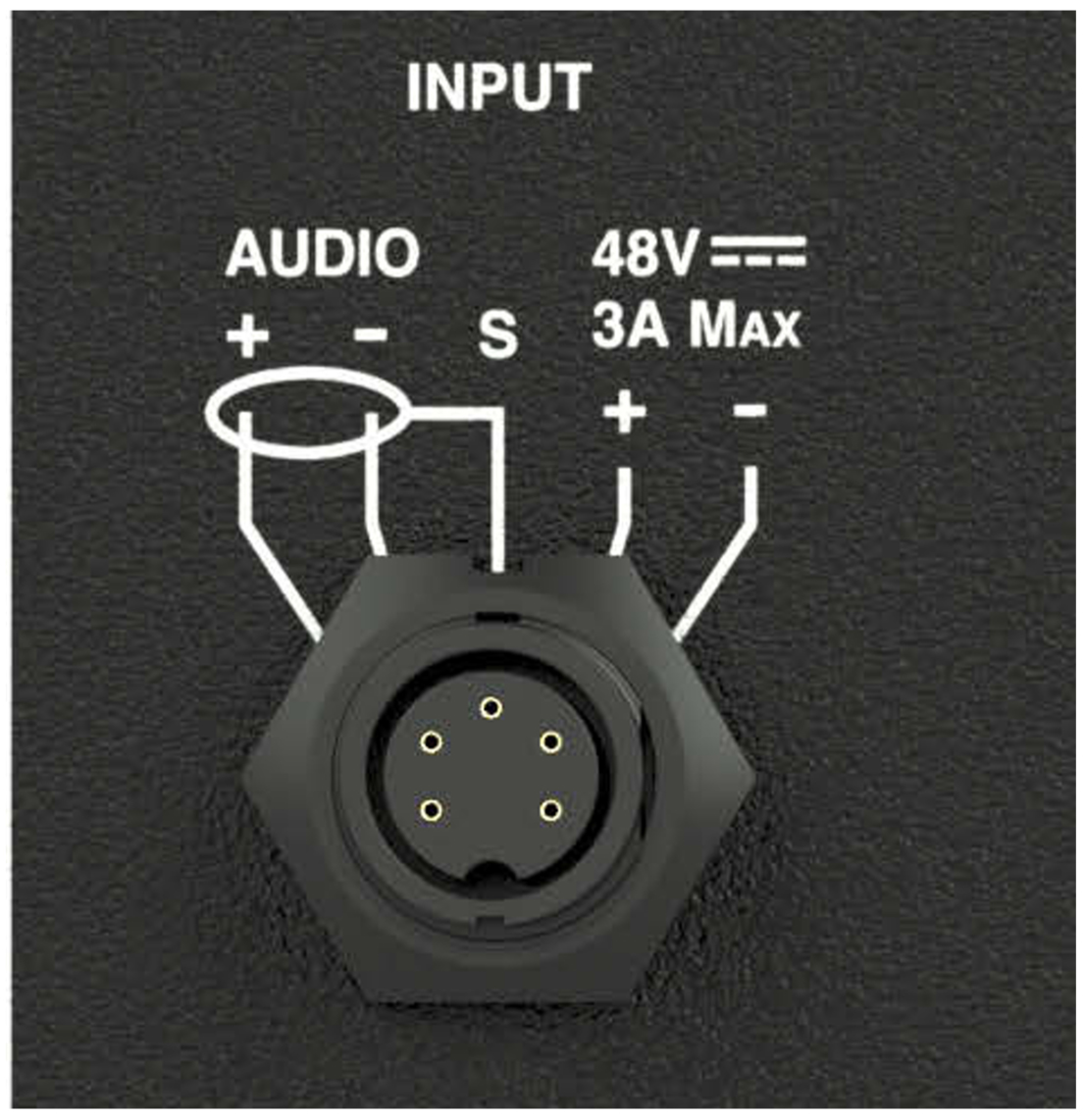 |
EN3 5-Pin Male Connector
Depending on the subwoofer’s connector, the MM-10XP ships with either a single Phoenix cable connector or an EN3-to-pigtail cable for constructing loudspeaker cables.
Note
The pin outputs for the MM-10XP EN3 connector is identical to that of the MM-4XP. However, the MM-10XP EN3 connector has been rotated to accommodate the unit’s internal connections.
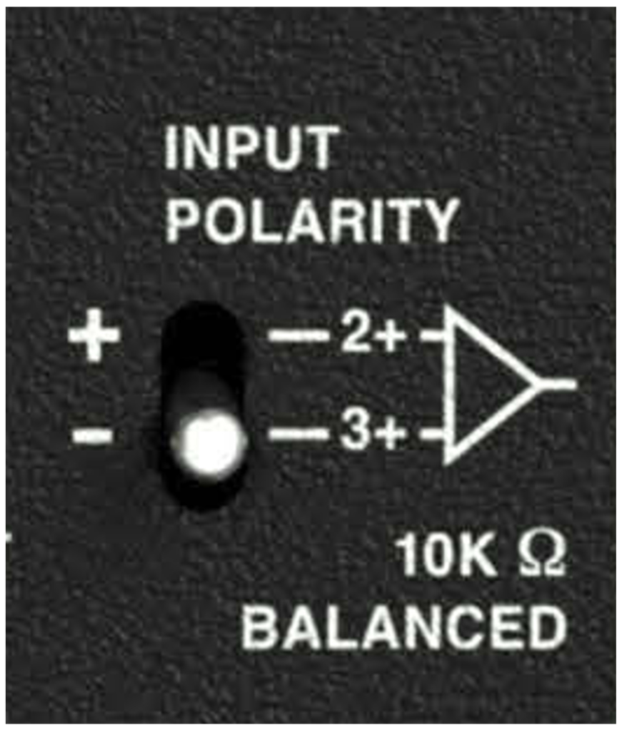
MM-10XP Input Polarity Switch
The Input Polarity switch swaps the polarity of the audio source signal, which is sometimes necessary to acoustically align the subwoofer with other loudspeakers in the system. When the switch is in the up (non-inverting) position, the positive audio pin (+) is hot relative to the negative audio pin (–), resulting in a positive pressure wave when a positive signal is applied to the positive pin. When the switch is in the down (inverting) position, the negative audio pin (–) is hot relative to the positive audio pin (+), resulting in a positive pressure wave when a positive signal is applied to the negative pin.
 |
MM-10XP Input Polarity Switch
Note
The text for the Input Polarity switch on the MM-10XP rear panel shows Pin 2 and Pin 3, which is the convention used for the MM-10AC and MM-10ACX models. However, the MM-10XP Input Polarity switch actually reverses the polarity for Pin 4 and Pin 5 of its input connector.
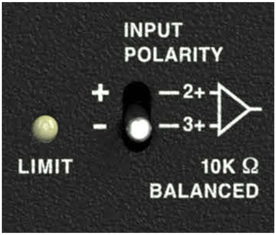
MM-10XP Limit LED
The MM-10XP has a three-color Limit LED on its rear panel that changes color to indicate the subwoofer’s status.
 |
MM-10XP Limit LED
Powering On (Green)
When powering up the MM-10XP subwoofer, the following startup events occur and are indicated by the Limit LED:
The LED flashes green and then yellow during power-up.
The LED turns solid green indicating the subwoofer is ready to reproduce audio.
Caution
If the Limit LED turns red and stays solid red after powering up and the audio is muted, the subwoofer has encountered a failure and may need to be serviced. Contact Meyer Sound Technical Support.
If the Limit LED turns solid red and the MM-10XP continues to output audio, though at reduced levels, the subwoofer’s voltage may have dropped below 25 V DC. When these conditions are encountered, operation of the subwoofer should cease and its power supply and cabling should be verified.
Limiting (Yellow)
Limiting activity is indicated when the Limit LED turns yellow. When engaged, the limiter protects the subwoofer’s driver and prevents signal peaks from causing excessive distortion in the subwoofer’s amplifier, thereby preserving headroom and maintaining smooth frequency responses at high levels. When the level returns to normal, below the limiter’s threshold, the LED turns green and limiting ceases.
The MM-10XP performs within its acoustical specifications at normal temperatures when the Limit LED is green, or if the LED turns yellow for two seconds or less and then returns to green for at least one second. If the LED remains yellow for longer than three seconds, the subwoofer enters hard limiting where:
Increases to the input level have no effect.
Distortion increases due to clipping and nonlinear driver operation.
The drivers are subjected to excessive heat and excursion, which will compromise their life span and may eventually lead to damage over time.
Caution
The Limit LED turns yellow when the subwoofer’s signal rises 2 dB above the limiting threshold, and indicates a safe, optimum level has been exceeded. If the MM-10XP subwoofers in a system begin to limit before reaching the desired SPL, consider adding more subwoofers to the system to achieve the desired SPL without exposing the subwoofers to excessive levels and possible overheating.
MM-10XP Temperature and Limiting
The Limit LED turns solid yellow when its heat sink temperature reaches 65° C (145° F), indicating the unit is reaching its maximum heat dissipation and a reduction in SPL is recommended. While the MM-10XP will continue to operate while the LED is yellow, the limiter threshold is lowered to a safe level (causing the output level to be lowered by 6 dB) to prevent the subwoofer from overheating. When the temperature of the heat sink cools to 50°C (122°F), the LED changes from yellow to green and the limiter threshold returns to normal.
Clipping (Red)
The Limit LED flashes red when its input signal causes the amplifier to overload. If the LED flashes red continuously, the subwoofer is severely overloaded and a reduction in the input level is recommended.
Caution
If the Limit LED turns solid red and the subwoofer continues to output audio, though at reduced levels, the subwoofer’s voltage may have dropped below 90 V AC. When these conditions are encountered, operation of the sub-woofer should cease and its power supply and cabling should be verified.
MM-10XP Current Draw and Cable Requirements
Each MM-10XP subwoofer draws a maximum current of 3.31 A average and 3.45 A peak from the 48 V DC output of the MPS-488HP. The current draw for the MM-10XP is dynamic and fluctuates as operating levels change. The cabling between the MM-10XP and the MPS-488HP adds resistance and hence causes a voltage drop at the subwoofer. Because lower DC voltages compromise amplifier performance (peak SPL), and in some cases frequency response, cable resistance should be kept to a minimum.
Note
For long cable runs, you can use a large cable gauge for DC power and a separate balanced audio cable for audio.
Cable Lengths and Cable Gauges for MM-10XPs
When connecting an MM-10XP to an MPS-488HP channel output, you can use cable lengths of up to 150 feet with only 1 dB of peak SPL loss using 18 AWG wire. Longer cable lengths are possible with heavier wire gauges (see the tables below).
Cable Gauge | Resistance (Ω/ft) | Approximate Max. Length |
|---|---|---|
12 AWG | 0.0016 | 600 ft |
14 AWG | 0.00253 | 375 ft |
16 AWG | 0.00402 | 237 ft |
18 AWG | 0.00636 | 150 ft |
20 AWG | 0.01008 | 87 ft |
Cable Gauge | Resistance (Ω/m) | Approximate Max. Length |
|---|---|---|
2.50 mm2 | 0.0052 | 157 m |
1.50 mm2 | 0.01076 | 87 m |
1.00 mm2 | 0.02087 | 45 m |
0.75 mm2 | 0.03307 | 27 m |
Note
When connecting an MM-10XP to an MPS-488HP channel output, the total cable resistance should not exceed 2 ohms.
Calculating the Maximum Cable Length
The maximum cable length for an MM-10XP can be calculated with the following formula:
maximum length = 2 Ω / 2 * cable resistance (in Ω/ft)
For example, the maximum length of an 18 AWG cable with a resistance of 0.00636 Ω/ft is 157.2 feet
(2 Ω/ 2 * 0.00636 Ω/ft).
Wiring MM-10XP Loudspeaker Cables with Belden 1502 Cable
When wiring MM-10XP loudspeaker cables with Belden 1502 or an equivalent cable, use the conventions in Table 3. The red and black wires in the Belden 1502 cable have a thicker gauge than the other three wires and should be used for DC power. The blue, white, and shield wires are shielded together and should be used for audio.
 |
Belden 1502 Composite Cable
Wire | Gauge | Gauge |
|---|---|---|
Red | DC power, positive (+) | 18 AWG |
Black | DC power, negative (–) | 18 AWG |
White | Balanced audio, positive (+) | 22 AWG |
Blue | Balanced audio, negative (–) | 22 AWG |
Shield | Balanced audio, shield | 24 AWG |
Note
Both ends of the loudspeaker cable should be wired so that the pins in the MM-10XP input connector align with those in the MPS-488HP channel output connector.
Wiring EN3-to-Pigtail Cables
MM-10XPs equipped with EN3 connectors are shipped with one 10-foot EN3 5-pin female-to-pigtail cable. The EN3 end of the cable connects directly to the MM-10XP input connector. The pigtail end of the cable can be equipped with either an EN3 5-pin male connector for connecting to the MPS-488HPE power supply, or a Phoenix 5-pin female connector for connecting to the MPS-488HPP power supply. The pigtail can also be spliced to a longer loudspeaker cable or to a junction box. The included EN3-to-pigtail cable uses a multiconductor cable, which can be wired for both DC power and balanced audio. The EN3- to-pigtail cable is available in plenum or regular (non-plenum) versions.
Note
For a complete list of cables and cable connectors available from Meyer Sound that can be used with the MM-10XP subwoofer and MPS-488HP power supply, see MM-10 Accessories.