QuickFly Rigging
Important Safety Considerations
When installing Meyer Sound loudspeakers and subwoofers, the following precautions should always be observed:
All Meyer Sound products must be used in accordance with local, state, federal, and industry regulations. It is the owner’s and user’s responsibility to evaluate the reliability of any rigging method for their application. Rigging should only be carried out by experienced professionals.
Use mounting and rigging hardware that has been rated to meet or exceed the weight being hung.
Make sure to attach mounting hardware to the building’s structural components (roof truss), and not just to the wall surface.
Make sure bolts and eyebolts are tightened securely. Meyer Sound recommends using Loctite® on all threaded fasteners.
Inspect mounting and rigging hardware regularly. Immediately replace any worn or damaged components.
750-LFC Rigging Options
The table below summarizes the available rigging options for the 750-LFC loudspeaker. For complete information about rigging hardware, including dimensions, weight, configuration, and load ratings, refer to the MG-MINA/LINA/750-LFC Assembly Guide (PN 05.207.101.02).
Model | Weight | Features | Required Quick- Release Pins | Required Shackles |
|---|---|---|---|---|
MRK-750 rigging kit PN 40.271.009.01 | 25 lb (11.3 kg) | Upgrade kit to allow the 750-LFC loudspeaker to be flown and groundstacked with the MG-MINA/LINA/750-LFC grid; includes hardware for the upgrade, captive GuideALinks and quick-release pins. | 0.25 in x 0.53 in, (black button) PN 134.039 qty 10 included | — |
MG-MINA/LINA/750-LFC multipurpose grid assembly kit (PN 40.207.101.01) | 39 lb (17.7 kg) | With some restrictions, flies up to 16 LINA cabinets at a 5:1 safety factor and BGV C1 with some angle restrictions (additional load ratings are possible—use MAPP to verify load ratings); supports mixed arrays of LINA and 750-LFC loudspeakers without transition hardware; accommodates a variety of pickup configurations with four corner and 11 center pickup points; can also be used for groundstacking. | 0.25 in x 0.90 in (black button with 6-inch lanyard), PN 134.036, qty 8 included | 5/8-inch or 3/4-inch |
MG-MINA/LINA/750-LFC multipurpose grid with GLK-750-LFC assembly kit (PN 40.207.101.02) | 39 lb (17.7 kg) | With some restrictions, flies up to 16 LINA cabinets at a 5:1 safety factor and BGV C1 with some angle restrictions (additional load ratings are possible—use MAPP to verify load ratings); supports mixed arrays of LINA and 750-LFC loudspeakers without transition hardware; accommodates a variety of pickup configurations with four corner and 11 center pickup points; can also be used for groundstacking; includes MG-MINA to 750-LFC Grid Link (GLK-750-LFC). | 0.25 in x 0.90 in (black button with 6-inch lanyard), PN 134.036, qty 10 included | 5/8-inch or 3/4-inch |
GLK-750-LFC grid link upgrade kit PN 40.207.301.01 | 2 lb (0.9 kg) | Includes two grid links to upgrade existing MG-MINA/LINA grids (PN 40.207.101.01). These 2 rear links effectively increase the load rating for the grid when attaching 750-LFC loudspeakers. Alway use MAPP to verify load ratings. | 0.25 in x 0.90 in (black button with 6 in lanyard), PN 134.036, qty 2 included | — |
MVP motor Vee plate kit PN 40.215.184.01 | 20 lb (9.1 kg) | Fine tunes the horizontal aim of arrays; compatible with MTG-LEO-M, MTG-LYON, MTG-1100, MG-LEOPARD/900, and MG-MINA/LINA/750-LFC grids. | — | 3/4-inch or 7/8-inch |
PBF-LINA pull-back frame kit PN 40.271.080.01 | 4 lb (1.8 kg) | Attaches to the bottom of LINA and 750-LFC arrays (to the bottom cabinet) and provides pull-back for extreme array downtilt | 0.25 in x 0.90 in (black button with 6-inch lanyard), PN 134.036, qty 2 included | 1/2-inch |
MCF-750 (no rigging) caster frame kit PN 40.271.070.03 | 28.7 lb (13.0 kg) | Safely transports up to three 750-LFC cabinets. This caster frame is for cabinets without rigging. | no pins | — |
MSA-STAND Adapter Cup 35MM (PN 40.086.013.01) | 0.3 lb (0.14 kg) | This compact cup-type adapter can be used to mount an ULTRA Series Mounting Yoke on a pole to allow for easy pan- ning and tilting of an ULTRA Series loudspeaker. | — | — |
35MM Pole Stand Adapter assembly kit PN 40.010.971.01 | 0.36 lb (0.16 kg) | This large base stand adapter can be used to mount the MYA-MINA/LINA Yoke or MUB-MINA/LINA on a pole to allow easy tilting of a MINA or LINA loudspeaker. | — | — |
MPK-POLE-35MM-M20 Adjustable Pole Mount kit (PN 40.010.973.01) | 8 lb (3.62 kg) | Adjustable length 927–1524 mm (36.5–60 in), 35 mm (1.375 in) pole with assisted lift. Lower shaft fits 35 mm cups or use the removable M20 threaded lug for added stability. Upper shaft includes a PAS-M20 Adapter Sleeve to fit loudspeakers with 35 mm and M20 internal pole mounts onto a 35 mm speaker stand. (Can also buy the PAS-M20 Adapter Sleeve separately). Additional 35 mm to 38 mm (1.5 in) adapter included. Also includes a 35 mm pole socket mount cup with M20 thread for the 750-LFC pole mount; using this cup provides a more stable connection. | — | — |
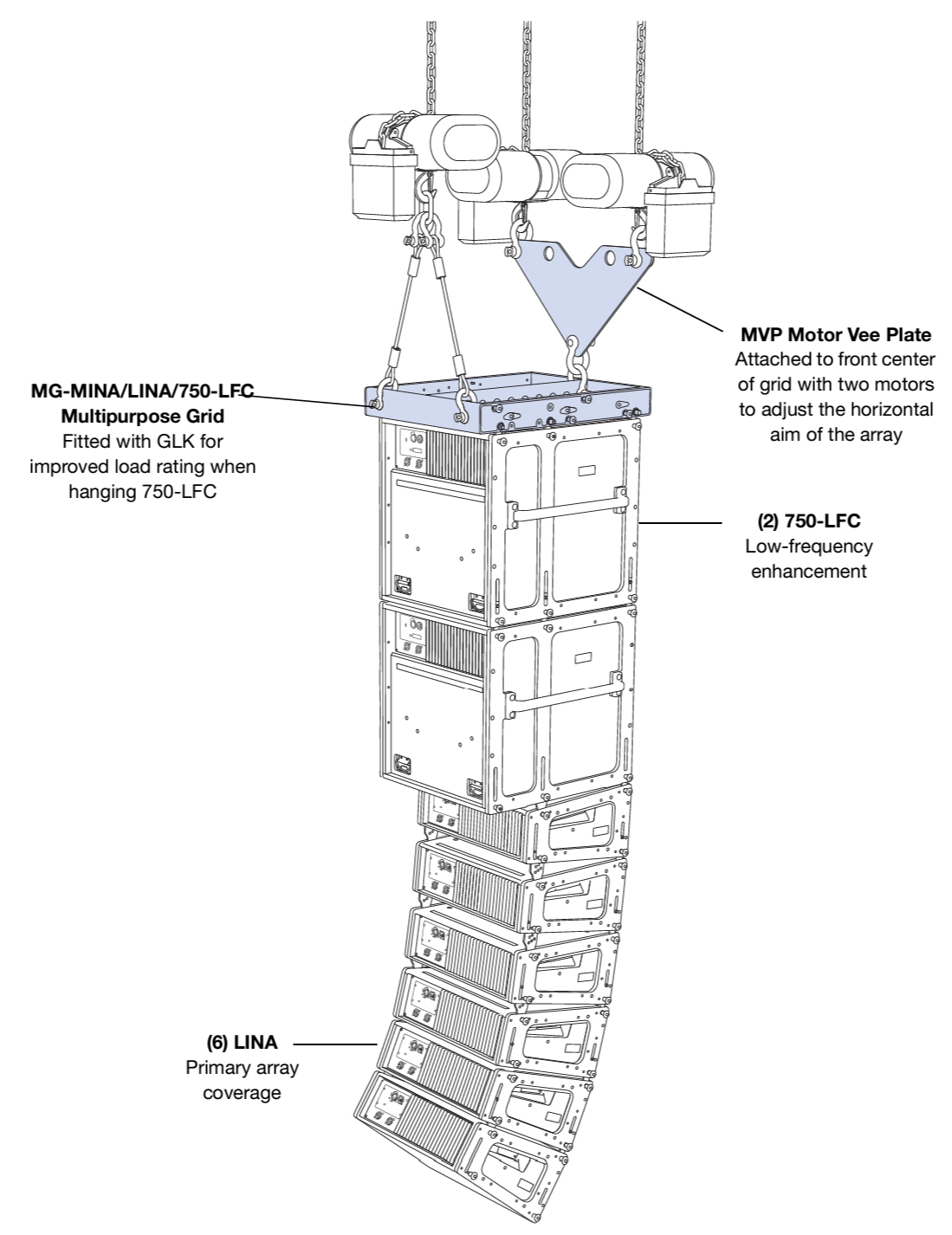
Rigging Example, Mixed Array with 750-LFCs and LINAs
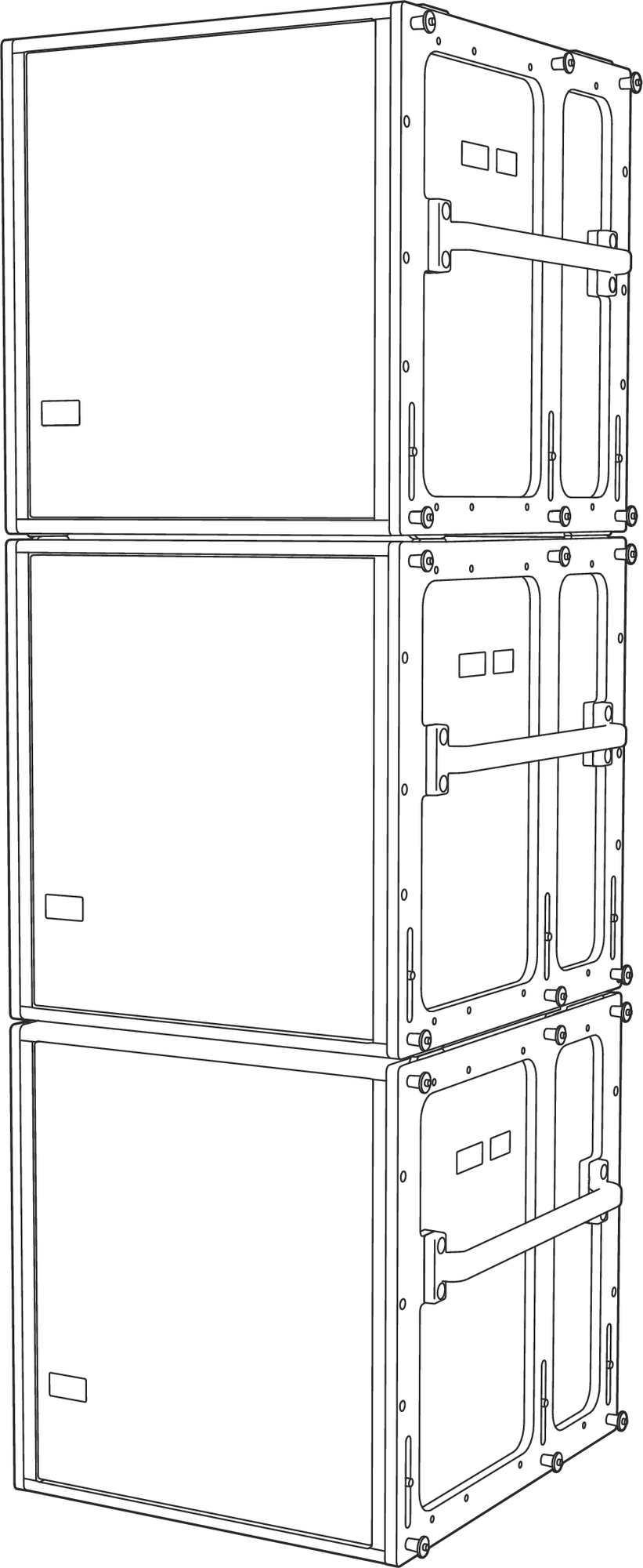
Ground stacking 750-LFC Loudspeakers (without grid)
750-LFC loudspeakers can be ground-stacked up to three units high, with or without the MRK-750 rigging kit. Protective plastic skids that align with the slots on the cabinet top are included on the bottom of the 750-LFC cabinet. Units can be stacked normally or reversed for cardioid configurations.
When ground stacking 750-LFC loudspeakers, make sure the skids for each unit align with the slots in the cabinet tops. When equipped with the MRK-750 rigging kit, the 750-LFC loudspeaker can be ground-stacked on the
MG-MINA/LINA/750-LFC grid with LINA loudspeakers for mixed groundstacks. (See the MG-MINA/LINA/750-LFC Rigging Assembly Guide).
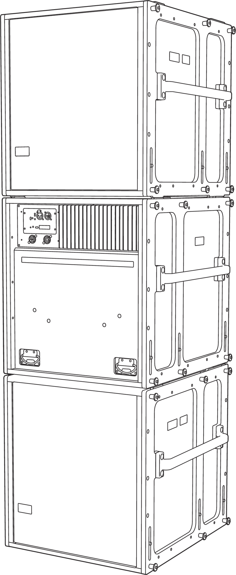
750-LFC Groundstack (With Rigging)
Caution
As a safety precaution and to avoid tipping, a maximum of three cabinets is supported for ground stacked 750-LFC loudspeakers.
Note
750-LFC need not be equipped with the MRK-750 rigging kit for secure ground stacking of up to three cabinets.
750-LFC Cardioid Arrays
The 750-LFC loudspeaker can be configured in cardioid arrays to reduce undesirable low-frequency leakage behind the loudspeakers. The loudspeaker’s linearity ensures that cardioid patterns behave accurately even at very high levels. Cardioid arrays are achieved by placing three units coplanar to each other (in either a groundstacked or flown array) with one unit facing the opposite direction, as shown in the figure below. Apply signal processing to the rear-facing unit with polarity opposite of the front-facing units and add an additional delay of 2.9 ms relative to the front-facing units. This configuration yields output from the rear-facing unit that cancels output normally present behind the array from the front-facing loudspeakers.
750-LFC Groundstack (Without Rigging)
Caution
As a safety precaution and to avoid tipping, a maximum of three cabinets is supported for ground stacked 750-LFC loudspeakers.
Note
750-LFC need not be equipped with the MRK-750 rigging kit for secure ground stacking of up to three cabinets.
750-LFC cardioid arrays can also be flown from the MG-MINA/LINA/750-LFC multipurpose grid. For more information, see the MG-MINA/LINA/750-LFC Rigging Assembly Guide.
To achieve an accurate cardioid pattern, you must use Meyer Sound’s MAPP prediction software. Use MAPP to calculate the appropriate ratio of forward- to rear-facing loudspeakers, as well as the processor settings for polarity. A myriad of possible cardioid and directional configurations can be calculated and predicted with MAPP. For more information, contact Meyer Sound Technical Support.
MRK-750 Rigging Kit
The optional MRK-750 rigging kit allows the 750-LFC loudspeaker to be flown and ground-stacked with the MG-MINA/LINA/750-LFC multipurpose grid. The kit also allows 750-LFC loudspeakers to be flown and ground-stacked with LINA loudspeakers with no transition hardware. The rigging kit is available as a factory-installed option or as a field upgrade and uses rugged GuideALinks and intuitive quick-release pins to securely link adjacent loudspeakers in flown and ground-stacked array configurations.
Note
For more information about the MRK-750 rigging kit, including its kit contents, weight, and installation instructions, refer to the MG-MINA/LINA/750-LFC Assembly Guide (PN 05.207.101.02) available at meyersound.com/documents.
750-LFC GuideALinks
When equipped with the MRK-750 rigging kit, the 750-LFC cabinet includes six captive GuideALinks and six mating link slots that link to adjacent units in flown and ground-stacked arrays. Located at the bottom of the cabinet, GuideALinks drop down and into the link slots of the cabinet below it. GuideALinks extend and retract with knobs and are secured with two quick-release pins: one each in the top and bottom cabinets.
GuideALinks accommodate reversed units for cardioid arrays. The MRK-750 rigging kit includes ten loudspeaker quick-release pins (0.25 in x 0.53 in, black button, PN 134.039).
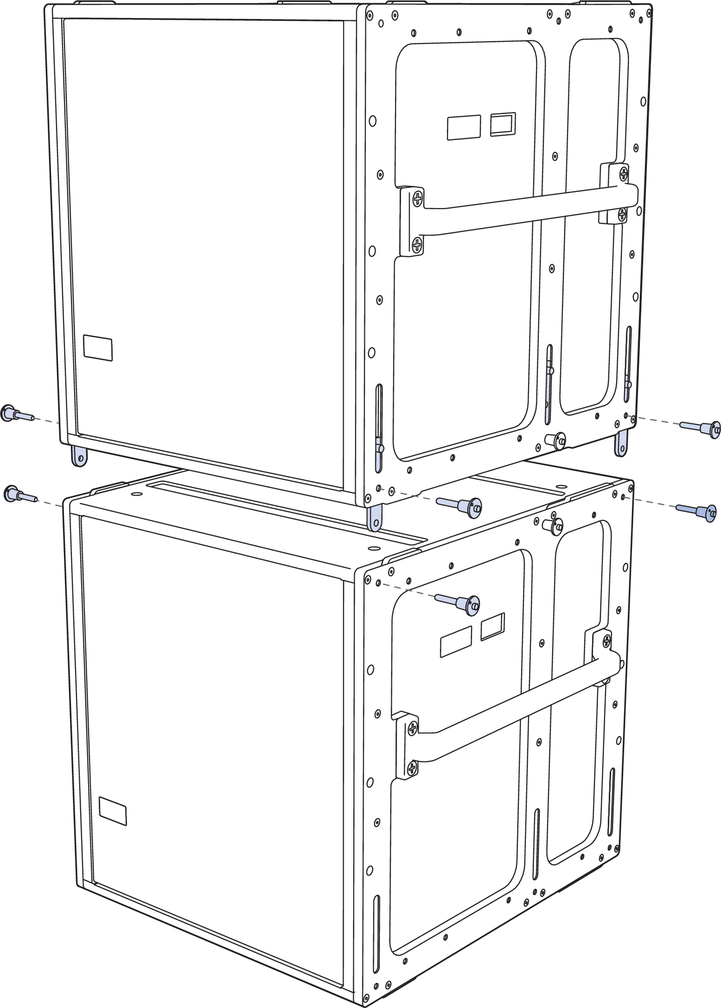
750-LFC loudspeakers with MRK-750 Rigging Kit, GuideALinks and Quick-Release Pins
GLK-750 Grid Link Kit
The original MG-MINA grid (PN 40.207.101.01) includes only the front and the middle links that allow flying MINA or LINA loudspeakers from it. Meyer Sound recommends NOT using the middle link to attach the 750-LFC. Using the middle link halves the load rating compared to using the front and rear attachment points.
Instead, Meyer Sound recommends using the updated version MG-MINA/LINA/750-LFC (PN 40.207.101.02) to hang 750-LFC loudspeakers. Existing grids can also be updated with the GLK-750-LFC grid link upgrade kit (PN 40.207.301.01), which includes the two rear links, installation hardware, and installation instructions (PN 17.207.301.01). Using the rear links, instead of the middle, effectively increases the load rating for the grid when attaching 750-LFC loudspeakers.
Caution
Always use MAPP to verify load ratings. Under no circumstance should all six links be used at the same time, as this approach will not add any load capability. In fact, the load capacity will decrease by about half of that provided by the rear links because it cannot be determined which links are actually under tension.
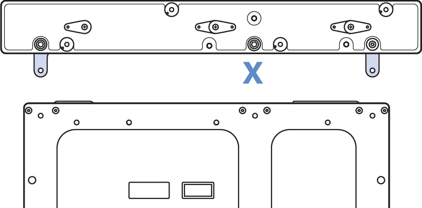
MG-MINA/LINA/750-LFC rigging grid
The 750-LFC cabinet’s GuideALinks accommodate both 750-LFC and LINA loudspeakers without transition hardware. The front and rear GuideALinks are used when flying the 750-LFC below the MG-MINA/LINA/750-LFC grid, or when flying it below another 750-LFC (Figure 20). The configuration of the 750-LFC loudspeaker’s GuideALinks, front and rear, determines its splay angle. The four corner link slots on the top of the 750-LFC cabinet accept GuideALinks from flown 750-LFC loudspeakers. The front and middle link slots accept LINA GuideALinks when flying LINA loudspeakers below the 750-LFC, as shown in the figure below. The configuration of LINA loudspeaker’s GuideALinks, front and rear, determines its splay angle.
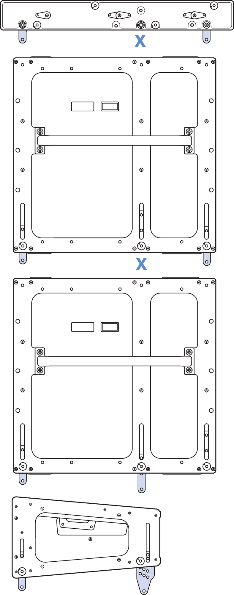
FlownMG-MINA/LINA/750-LFC, 750-LFC and LINA with GuideALink Attachments
The 750-LFC cabinet’s front and middle links insert into slots in the MG-MINA/LINA/750-LFC grid when groundstacking the 750-LFC. The 750-LFC cabinet’s front and middle GuideALinks slots are used when stacking LINA loudspeakers on top of the 750-LFC, as shown in the figure below.
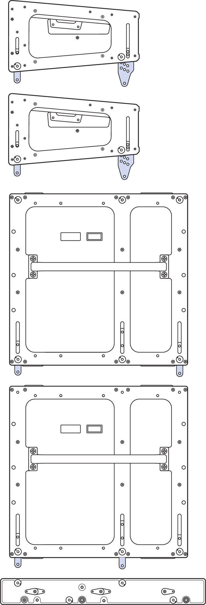
Groundstacked LINA and 750-LFC with GuideALink Attachments
Caution
Do not use the 750-LFC loudspeaker’s middle GuideALinks when flying the 750-LFC below the MG-MINA/LINA/750-LFC grid or when flying below another 750-LFC. Always use the front and rear GuideALinks when flying the 750-LFC.
750-LFC Splay Angles
The front and rear GuideALinks attach at angles of 0°, 1.5°, 3.25° or 4.75°, allowing for curved 750-LFC arrays. Because the cabinet’s front and rear GuideALinks are symmetrical, the curved arrays can also include cardioid configurations.
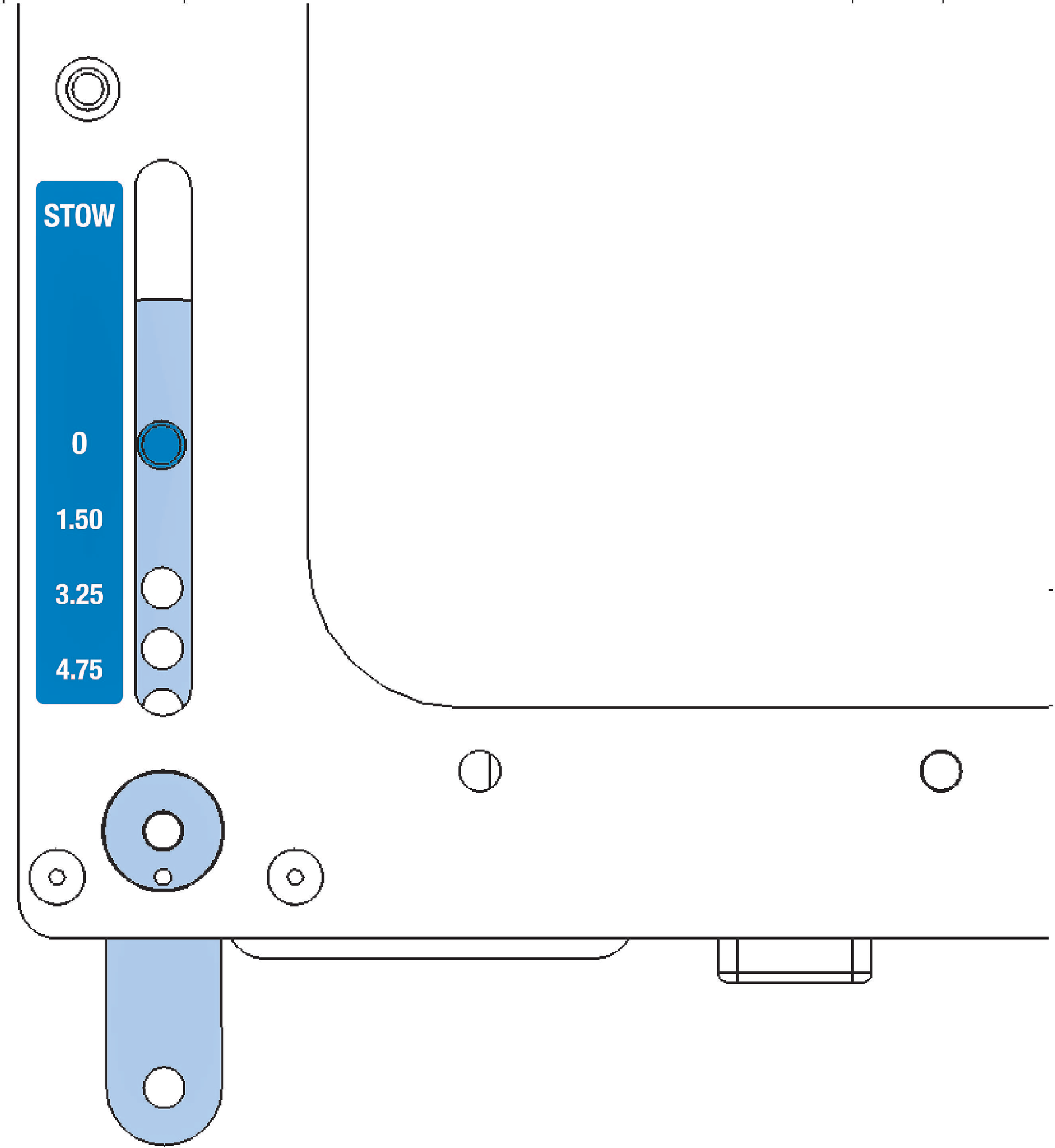
750-LFC Front GuideALinks Label
The labels next to the front and rear GuideALinks indicate the splay angle between cabinets (when the opposing links are set to 0°). As the links are moved down, the splay angle increases. To stow the GuideALinks, move them all the way up to STOW and pin them.
Note
Curved 750-LFC arrays do not provide directionality for low-frequency content. The curved array capability of the 750-LFC is provided to minimize unwanted high-frequency reflections from adjacent mid-high arrays and to aesthetically mimic the curvature in adjacent mid-high arrays.
Pole-mount Receptacle
All 750-LFC cabinets come standard with an integral pole-mount receptacle that allows the subwoofer to be easily paired with ULTRA Series loudspeakers. You can mount Meyer Sound loudspeakers on top of the 750-LFC with a heavy-duty pole and pole-stand adapter.
The 750-LFC pole-mount receptacle comes in two sizes:
U.S. version: 1 1/2 in (38 mm)
E.U. version: 1 3/8 in (35 mm, M20 thread at the bottom)
Meyer Sound offers accessories for this purpose:
35MM Pole Stand Adapter (PN 40.010.971.01)
MSA-STAND Adapter Cup 35MM (PN 40.086.013.01)
MPK-POLE-35MM-M20 Adjustable Pole Mount (PN 40.010.973.01)
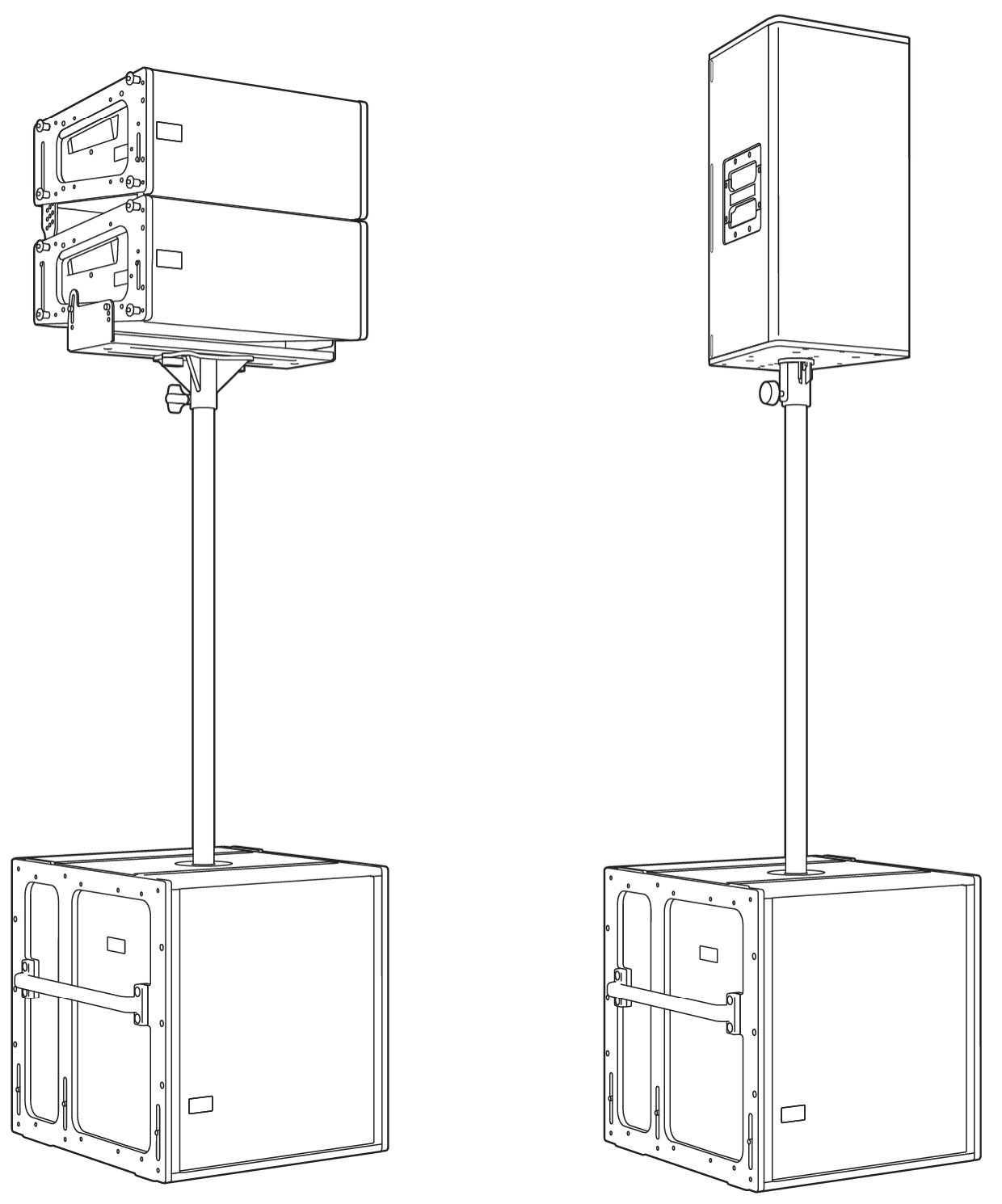
Pole and Pole-Mount Adapter: 750-LFC with 2 LINA, MUB-MINA/LINA U-bracket, and 35MM Pole Stand Adapter (left); 750-LFC with Ultra Series speaker on MSA-STAND Adapter Cup 35MM (right)
The following Meyer Sound loudspeakers can be mounted on top of the 750-LFC cabinet. Make sure that the pole and pole-mount adapter can support the weight of the mounted loudspeakers and that they are installed according to the manufacturer’s instructions.
One ULTRA-X40/42 loudspeaker (55 lb, 25 kg)
One MINA or LINA loudspeaker with MUB-MINA/LINA U-bracket (47 lb, 21.3 kg)
Two MINA or LINA loudspeakers with MUB-MINA/LINA U-bracket (90 lb, 40.8 kg)
One UPA-1P or UPA-2P loudspeaker (77 lb, 34.9 kg)
One UPJ-1P loudspeaker (46 lb, 20.9 kg)
One UPJunior loudspeaker (28 lb, 12.7 kg)
Two UPJunior loudspeakers with MUB-UPJunior U-bracket and MAAM-UPJunior array adapter (70 lb, 31.8 kg)
Caution
Make sure the pole and pole-mount adapter can support the total weight of the mounted loudspeakers. In particular, heavier loudspeakers are less stable on taller pole mounts. Observe all safety precautions specified by the pole manufacturer.
Tip
For more details about the MPK-POLE-35MM-M20 Adjustable Pole Mount Kit, see ULTRA-X40/42 Operating Instructions.
MCF-750 Caster Frame
The MCF-750 caster frame safely transports up to three 750-LFC loudspeakers, making it easy to assemble and disassemble arrays in blocks of three cabinets. There are two versions available: one for MRK-750-equipped cabinets (PN 40.271.070.02), the other for cabinets without rigging (PN 40.271.070.03). The caster frame’s sturdy construction allows it to be conveniently moved with forklifts (when cabinets are equipped with the MRK-750 rigging kit only). The MCF-750 can also be used to support 750-LFC loudspeakers in groundstacked configurations.

MCF-750 Caster Frame for cabinets without rigging
MCF-750 Caster Frame for cabinets with rigging
The caster frame for 750-LFC cabinets equipped with the MRK-750 rigging includes four fixed, 0° link slots that attach to the cabinet at the bottom of the stack and are secured with the quick-release pins (0.25 in x 0.90 in, black button with 6-inch lanyard, PN 134.036) included with the 750-LFC.
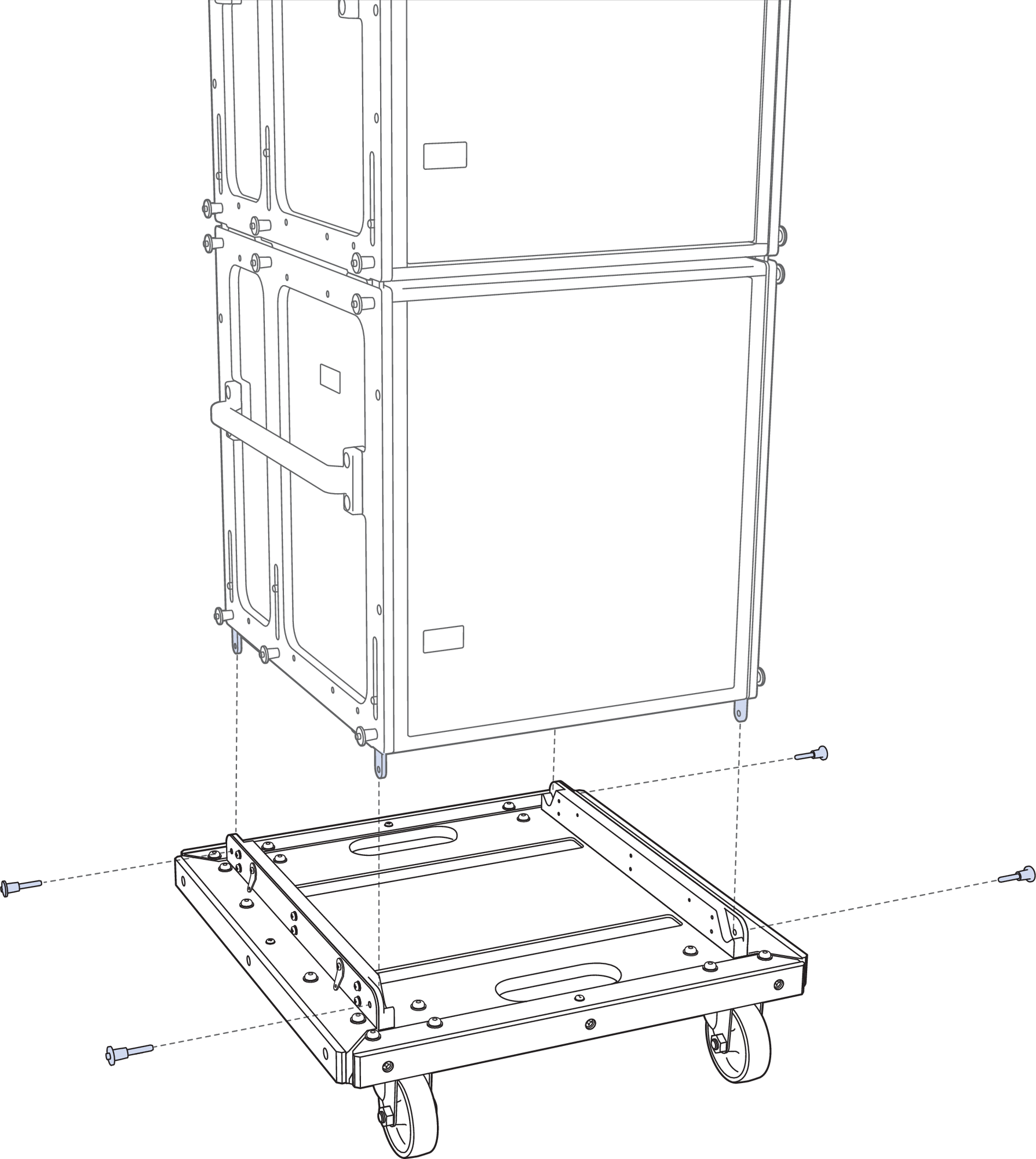
MCF-750 Caster Frame with 750-LFC Stack, Exploded View
Caution
Two versions of the MCF-750 caster frame are available from the factory—configured for cabinets with the MRK-750 rigging kit (PN 40.271.070.02) or without (PN 40.271.070.03)
750-LFC cabinets need not be equipped with the MRK-750 rigging kit for transport with the caster frame. The loudspeaker skids ensure that cabinets stack cleanly on the caster frame. However, to avoid tipping, straps (not included) should be used when transporting cabinets that have not been fitted with the MRK-750 rigging kit.
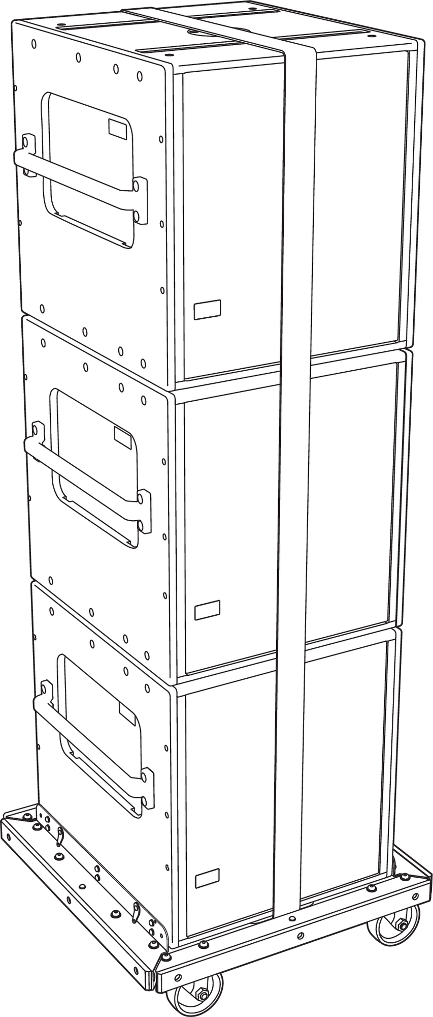
MCF-750 Caster Frame, (3) 750-LFCs (without Rigging), using straps (Not Included)
50-LFC cabinets equipped with the MRK-750 rigging kit provide for more secure transport, because the bottom cabinet can be linked and pinned to the caster frame. The three cabinets can be linked and pinned together as well.
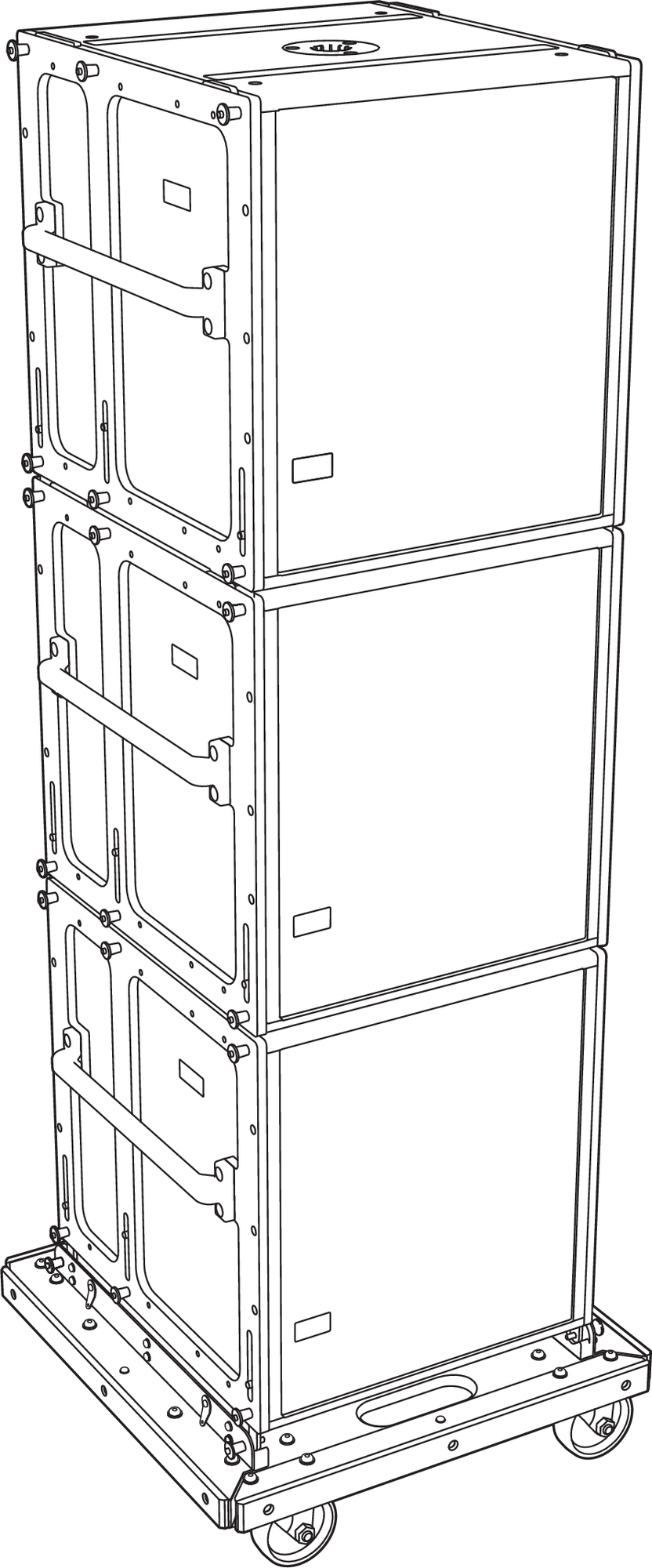
MCF-750 Caster Frame, (3) 750-LFCs (with Rigging)
Tip
Durable nylon pullover covers, sized for stacks of 2 units or 3 units, are available to protect 750-LFC cabinets during transport. Special wraparound covers are also available to accommodate stacks with grids on top.
The MG-MINA/LINA/750-LFC grid can travel installed on top of 750-LFC stacks on the MCF-750 caster frame.
Safety Guidelines for the MCF-750 Caster Frame
Do not stack more than three cabinets on the MCF-750 caster frame.
Use straps when transporting 750-LFC loudspeakers that have not been fitted with the MRK-750 rigging kit.
To avoid tipping, transport stacks with loudspeakers linked and locked at 0-degree splay angles.
Forklifts should only be used to move the MCF-750 caster frame when cabinets have been outfitted with the MRK-750 rigging kit and the cabinets have been securely linked.
When lifting a stack with a forklift, always keep the forks wide and close to the caster frame’s wheels. Failing to do so may bend the caster frame or cause the stack to tip.
When ground-stacking 750-LFC loudspeakers with the caster frame, make sure that all four caster wheels are blocked to prevent the stack from rolling away.
Caution
The caster frame must be removed before flying a loudspeaker array.