Controlling GALAXY processors with compass
Compass Control Software provides comprehensive control of GALAXY processors using an intuitive graphical user interface on a Mac® or Windows®-based computer. Compass provides control of all features on multiple units simultaneously. This chapter is a brief introduction to controlling the GALAXY processor via Compass and highlights some key GALAXY processor features.
Tip
Compass Go is an iPad application, a light version of the Compass Control software. It provides all the key functionalities of Compass with maximum mobility.
Note
Meyer Sound has developed videos to provide an overview of Compass Control Software; please visit meyersound.com/videos/#support
Meyer Sound Compass 4.3.6, Compass Go AM824, and their included GALAXY processor firmware are the last versions that support AM824 audio format. Compass 4.6 and above support AAF audio streams and CRF clock streams. GALAXY processors with different firmware will NOT be compatible with each other.
For most applications, Meyer Sound recommends upgrading GALAXY processors to the latest firmware, available for download at: meyersound.com/product/compass/
Setting preferences
Compass Control software allows users to set a wide variety of preferences, effectively customizing the interface to suit the needs of a particular application. If none of the Show Tab Controls, shown in the figure below, are selected, the Compass control window will only show the Preference setting tabs.
Each of these Preference tabs has a help button in the upper left corner that provides more detail about the various selectable options. There is also a button to Reset to Defaults if desired.
The GALAXY Preferences tab, shown in the figure below, has five sub tabs: Controls; Startup, Shutdown and Confirmation; Snapshot Recall; Select, Isolate and Linking; and Global Linking. The Controls tab has a drop-down menu to select delay units; all other preference options are indicated with square green buttons (on/off selections) and round blue buttons (either/or selections).
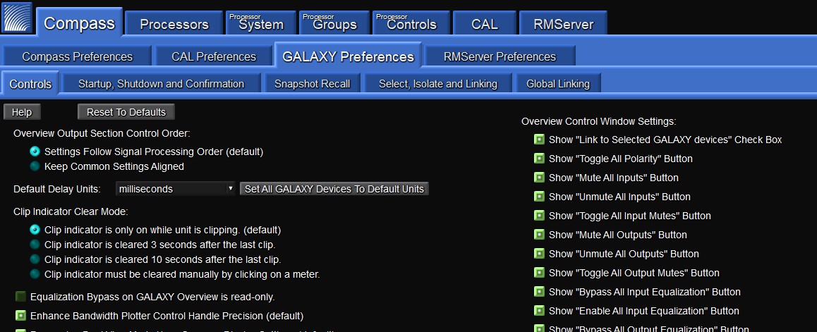
GALAXY Preferences tab
GALAXY processor user interface
To enter the GALAXY processor control area of Compass, select the Processors tab. The processors that have been automatically discovered will be listed here. If one or more processors are not listed, click the Find Devices button (upper-left). If the listed processors have a Status other than Available, click the Refresh button. Refresh only applies to devices already in the list after selecting Find Devices. When a processor is listed in the Inventory, the available GALAXY processor control tabs will appear next to the Inventory tab. The Refresh button next to Find Devices only applies to devices already in the list after selecting Find Devices.
Note
Find Devices uses mDNS protocol to discover devices. If “Find Devices” does not return any items, check to ensure mDNS is enabled.
Tip
Compass has context help available within the program. Look for a gray button labeled Help, or on the denser screens, a gray button with a small ? on it.
Meyer Sound has developed system example videos for the GALAXY processor that provide a good introductory overview. Visit: meyersound.com/videos/#support.
Inventory tab
Users can add, connect, and configure GALAXY processors within the Inventory tab. Select Show Global Project Features button at the top, which displays the options to save Global Projects, create Global Snapshots, and change the Global Environment settings. This tab provides the ability to:
Remove processors
Reorder the processors in the window
Link multiple processors together
See the detected version of GALAXY processor firmware
Connect/disconnect/refresh individual devices
Launch “Virtual” mode to work on a project without being connected to a real GALAXY processor (this feature also supports a demo mode with simulated meter values that sweep up and down)
Select whether a GALAXY processor is displayed in the main Compass window or a secondary window
Select whether or not the Systems tab will display a device’s settings.
If any of the processors are running firmware that is incompatible with the version of Compass, the firmware version will be displayed with an amber background rather than blue. The Galaxy firmware must be the version that corresponds with the Compass application being used. Either update the GALAXY processor firmware or use the version of Compass that corresponds to the GALAXY processor’s firmware.
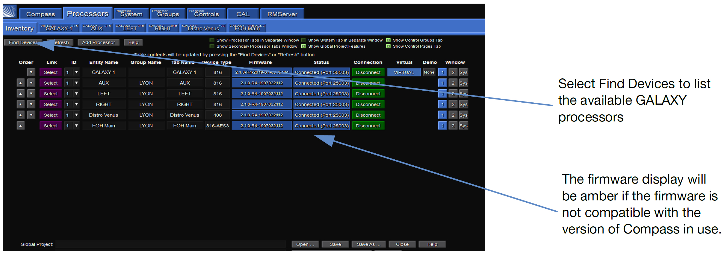
Inventory tab
Upgrading firmware
If firmware updating is required, see Network tab, or meyersound.com/videos/#support for a how-to video.
Individual processor control tab
Select the tab of a connected GALAXY processor at the top of the screen. The Overview tab will be displayed. Each processor tab has nine sub-tabs that provide controls to adjust the processor functions:
Project
Settings
Overview
Input Processing
Output Processing
Summing Matrix
Delay Matrix
Input Masters
Output Masters
A status bar is at the bottom of each GALAXY processor tab that includes:
Clock Status — Current clock status is displayed as locked or unlocked.
Project and Snapshot Controls — Current project and snapshot (see Projects tab) are displayed. The user can also save a project, update or create snapshots, and monitor whether or not a boot snapshot is enabled.
Channels Control — Three-row Channels bar allows a user to Select (link channels), Isolate (temporarily isolate a channel from other channels to which it is linked), and Link Groups (enable selection of multiple channels by selecting one) for all input and output channels.
Server Connection Status — Two small indicators in the bottom right will flash every couple of seconds when the server (processor) is properly connected. These lights signify that upload (ping) and download (pong) data transfers are happening.
Overview tab
The Overview tab is shown in the figure below. It provides a high-level view of GALAXY processor settings. The basic input and output settings can be modified by clicking, entering new values, or click-dragging controls. Many of the graphic elements are shortcuts to other tabs or open dialogs:
Input Processing
Summing Matrix
Output Processing
Product Integration Dialog
Atmospheric Correction Dialog
The dialog to adjust Product Integration settings can be accessed by clicking on the Product Integration indicator for each output. See Product Integration.
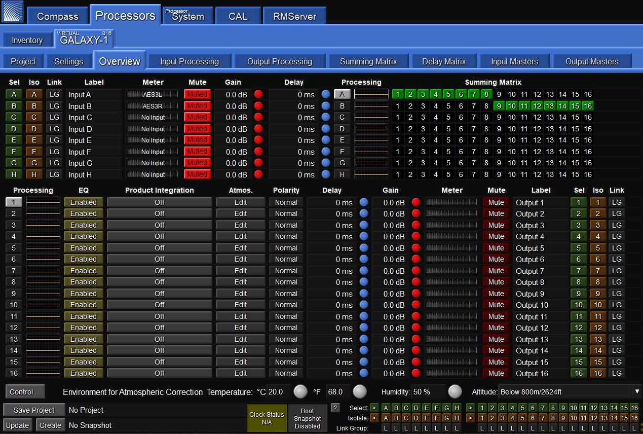
GALAXY Processor User Interface in Compass Control Software
Projects tab
GALAXY processor project files can be saved by the Compass Control software to the client computer. Project files contain all of the Snapshots stored in the processor and all of the current control point values.
A Snapshot contains all of the control point values of a processor when a Snapshot is created. The GALAXY processor can store up to 255 Snapshots in the Snapshot Library.
The relationship between the GALAXY processor and Compass is server/client: the GALAXY processor is the server, Compass the client. When a computer is connected to a GALAXY processor, the Compass Control Software reads and displays the current state of all control points and the list of Snapshots stored in the GALAXY processor. However, opening another GALAXY Project file (stored on the computer) will overwrite the Snapshot Library and, if selected, the current device settings.
Compass also has a Virtual mode that is selectable from the Inventory tab. This mode allows a user to work on a project file without being connected to real GALAXY processor hardware. In effect, Compass is connecting to a virtual GALAXY server.
Caution
Opening a project file in the Compass Control Software when the computer is connected to a GALAXY processor overwrites all stored Snapshots and the current device settings of the GALAXY processor if Load Device Settings is selected when the GALAXY Project is opened. To merge snapshots from another Project file into the current Snapshot library in a GALAXY processor, use the Merge Project option from the Project tab (click the More>> button for this option to appear).
Tip
Use Compass Control software to store GALAXY processor control point values as a Snapshot in the GALAXY processor. The Snapshot Library is stored as a Project on the client computer and can later be reloaded into the GALAXY processor.
Note
Firmware updates do not affect Snapshots or control point values. To restore factory defaults, see Network tab.
Settings tab
The Settings tab has eight sub-tabs: Network, Input and Output, SIM, Environment, Access, Low-Mid Beam Control, Link Groups, and Log.
Network tab
The Network tab lists the following GALAXY processor options:
Device Type
Device Name (editable)
Entity Name
Group Name (editable)
Serial Number
IPv6 Address
IPv4 Address (editable)
MAC Address
Front Panel LCD Display options (editable)
Color and Brightness
Date and Time (editable)
Operating Mode Indicator
Soft Reboot Options
Upload Firmware options
Edit Network Settings options
Firmware may be uploaded from this page by following these steps:
Reboot the GALAXY processor into Recovery Mode, enabling the Upload Firmware, and Upload Firmware to all GALAXY devices.
Firmware can be uploaded to one or all connected processors by clicking Upload Firmware or Upload Firmware to all GALAXY devices.
Select either the
.bluehornFirmwareor.galaxyFirmwarefile that matches the GALAXY processor type from the Compass Application folder.The firmware will begin uploading when OPEN is clicked. The progress is indicated in a pop-up window, which can be closed while the upload continues. While the firmware upload is in progress, the GALAXY processor will not pass audio and the tab color will change to amber.
The time of the GALAXY processor may be set to a specific time or to the connected computer’s time using the Set Device Time button. In this dialogue, there is an option to set just one, or all connected GALAXY processors to the new time.
The GALAXY front panel LCD color can be adjusted for brightness and color. The available options are Green, Blue, Cyan, Yellow and Magenta. The Front panel display can be set to Normal, Dim, and Bright.
There is also an option to reboot to the factory defaults by selecting the Reboot with Factory Defaults button on this page.
Identify button
Pressing the Wink button on the rear of a GALAXY processor will cause the device to enter the Identify Mode, a bidirectional identification feature. The front panel will flash, and Compass will show an indication on both the GALAXY processor’s Inventory tab and the Settings > Network tab (Identify button will flash) of each processor. To exit Identify Mode, push the Wink button on the processor again, or click on the Identify button on the Network tab in Compass.
Tip
Identifying a GALAXY processor and then naming that processor helps make identification easier.
Input and output
Under the Settings tab, the user can configure input channel types, AVB Control Mode, Channel Selection, System Clock, AES Output Clock (AES Version Only, see Clocking), and input/output voltage ranges.
Input Channel Types are configured individually to either Analog, AES3, or AVB. For the GALAXY 816 processor and the GALAXY 816-AES processor, AES connections are made to ports A, C, E, G; the companion ports B, D, F, and H must be left unconnected. For the GALAXY 408 processor, AES connections are made to connectors A and C; the companion ports B and D must be left unconnected. Compass indicates which XLR connectors are utilized based on the input channel’s analog or AES3 status.
AVB Control Mode: network digital source signals may be connected to the AVB/Network port connectors (labeled 1 and 2) on the GALAXY processor rear panel. These connectors allow for the usage of Milan-compliant AAF streams for Audio (see the AVB Networking Guide, available at https://meyersound.com/documents).
Milan-compliant AAF and CRF streams are supported for Clocking. There are two modes: Internal and External. Internal Mode allows the GALAXY Internal AVB connection manager to control all AVB Input Streams. External Mode disables the GALAXY Internal AVB connection manager and allows an external Milan controller to connect the AVB streams.
Only one signal type can be selected for each input. Outputs from available GALAXY processors will populate the AVB browser when that device is selected from the available Devices list. The Group can be selected from the Group selection menu. Connections can be established and disconnected.
AVB Stream Info: to access the AVB Stream Info, press the “Info” button on the Input and Output tab GUI, opening a secondary window. The left side lists data about the Primary input source and the right side lists data about the Secondary input source.
Channel Selection: “selected” channels are linked. Changes made to one selected channel will be made to all other selected channels of the same type (input or output) in a device. Depending on the Global Link Preferences, channels on other devices may be affected as well. Use Link Groups (Link Groups) to quickly select or deselect multiple channels. Selected channels have a green background.
AVB Output Settings: the Default Presentation Time can be set for each GALAXY processor on the Network from 0.250–2 ms; the default value is 2 ms. Reducing the value of the Presentation Time will lower the latency of the AVB stream output from a talker to a listener. The MSRP Accumulated Latency will display the worst case time through the network, and can be used as a reference of how low the Default Presentation Time can be set. In some cases, it is desirable to use a lower latency, which can be accomplished by reducing the Default Presentation Time. The Default Presentation Time should never be set lower than the MSRP Accumulated Latency.
For more information about network configurations and a discussion about Presentation Time, see the AVB Network Guide (PN 05.010.541.01) available at meyersound.com/documents
System Clock: the GALAXY System Clock can be configured to either the Internal Clock, an AVB Clock CRF, an AES input, or an AVB AAF Input. For the GALAXY 816-AES processor, the Word Clock (BNC connector) can also be configured as the GALAXY processor media clock. This option allows the GALAXY 816-AES3 processor to be synchronized to an external source for both the system clock and AES output clock, at 48 or 96 kHz. AES allows discrete values in the range from 20–216 kHz (see Input sample rates).
Note
“Media clock” is the common terminology used in the Milan specification. Within the GALAXY processor Settings: Input and Output tab, the media clock choice is selected under the “System Clock: Clock Mode” pull-down menu.
When an incoming 96 kHz AES signal is selected as a clock source under the system clock pull-down tab, disable the Asynchronous AES sample rate converters to reduce latency through the system. These ASRC converters are only available on the AES inputs and only required when the incoming AES signal does not match the 96 kHz internal clock frequency to within +/- 100 ppm.
Caution
When AES ASRC is enabled on an input, the clocking data associated with that input is removed by the GALAXY processor, and that input may not be used as a valid System Clock.
All AVB inputs must be synchronized to a common media clock, and the clock must originate from one of the incoming AVB sources and cannot be daisy-chained (see Common media clock for multiple interconnected GALAXY processors Common media clock for multiple interconnected GALAXY processors).
Input/Output Voltage Range: allows the user to set analog channels to either +16 dBu or +26 dBu. These settings only apply to analog channels.
SIM tab
Under the SIM tab, the user may configure settings related to the SIM Audio Analyzer. There are two probe points (SIM Console and SIM Processor) that can each be set to any of the five possible probe selections: Input Post Source Select, Input Post Processing, Output Post Matrix, Output Post EQ, and Output Post Processing.
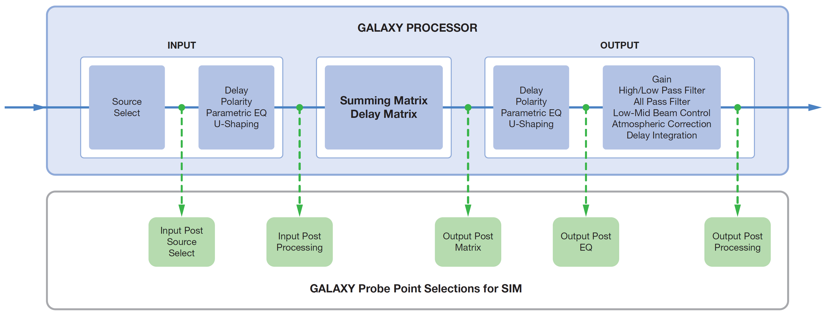
Possible GALAXY processor SIM probe point selections
Environment
The Environment tab is one place to adjust the global values for temperature, humidity, and altitude. These settings, in conjunction with the parameters of each output channel (Atmospheric Gain and Distance), recall filter settings to compensate for high-frequency attenuation due to propagation loss through air. There is also a square on/off toggle button to select whether or not to link Correction Distance and Atmospheric Gain Factor settings across all output channels.
Access
The Access tab allows a user to control access to various GALAXY processor settings, confining access to particular controls for different users based on their role settings. These settings apply to situations such as permanent installations where multiple users have access, or situations where various parts of show design are divided amongst several people.
Link Groups
Link Groups allows for the editing of multiple channels simultaneously. The Link Group index buttons are blue when enabled, yellow when bypassed, and gray when not in use.
Log
The Log tab displays a date and time-stamped running record of a GALAXY processor’s operation. This display is a subset of all log data (includes client level messages). For a more detailed log history (that might help Meyer Sound Tech Support, for example, in a debug situation), use the Save System Logs button under the Settings tab. Clicking this button will save more information, including kernel logs and operating system details.
Input Processing tab
The display under the Input Processing tab, shown in the figure below, is divided into two sections. The upper part provides a Plotter display, where a user can visualize input channel equalization. The plotter plots gain (left vertical axis) and phase (right vertical axis) against frequency (x-axis). If gain and phase happen to align, that situation is purely coincidental. Two select buttons on the top control whether the display is dual (two channels simultaneously) and whether or not to show the settings control mini tabs. When selected, three mini tabs will appear to the right of the display: Plotter, Handles, and Response:
The Plotter mini tab provides some axis control. It also allows control of the number and arrangement of plotters, and what to display or hide. More than one EQ plot may be shown at a time by selecting “Multiple” under the Plotter mini tab.
The Handles mini tab controls the display or removal of EQ handles in the plotter.
The Response mini tab controls whether to display or hide specific response curves in the plotter.
All of these mini tabs can be hidden from view by using the right/left blue arrows on the bottom right of the mini tab.
The bottom part of the tab displays the input processing control. This part of the display may be minimized by clicking the up/down arrow under the Plotter display. Within the control area under the Input Processing tab, a user may select the processing desired for each input. Possible processing includes Gain, Delay, 5-band Parametric EQ, and 5-band U-Shaping EQ.
This window has three tabs near the bottom left of the screen to control the processing parameters: Channel Settings, Parametric, and U-Shaping.
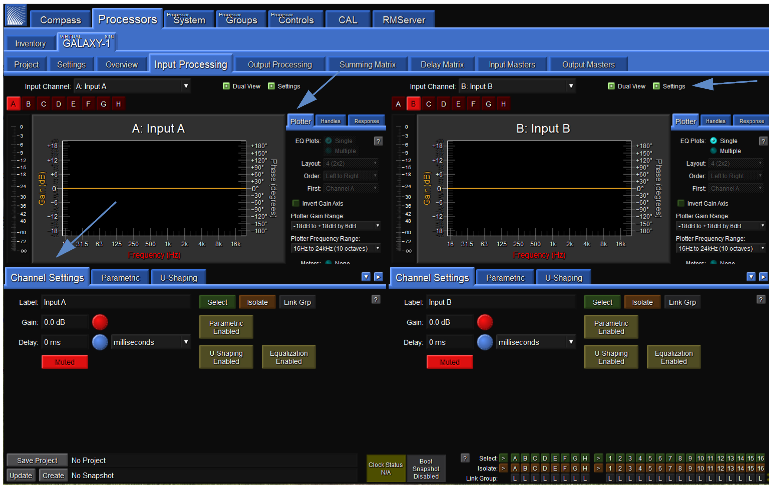
Processor > Input Processing tab
Channel Settings tab (Input Processing tab)
Under the Channel Settings tab in Input Processing, the user can set a Label, Gain value, Delay Value, Mute the Channel, and enable or bypass Parametric, U-Shaping, and/or all EQ for a particular input channel. Select the Input Channel to control via the drop-down menu or individual alphabetic channel buttons (e.g., A-H for a GALAXY 816 processor) above the plotter display.
The Label widget allows a user to enter a short text description of a Channel, Array Group, or Link Group. It is for informational purposes only.
The Gain widget lets the user increase or decrease the signal level by decibels (dB). The default assumes negative gain values. Entering any integer will result in the gain being set to the negative of that integer (e.g., “3” becomes -3 dB gain). (The default may be changed to positive gain values in the Compass Preferences tab.)
The Delay widget allows the user to add a delay in various units to an input channel or matrix input signal. The range is 0–500 ms.
Clicking the input channel Mute button prevents any signal from being sent to the matrix.
Clicking the Select button causes this channel to be linked to other input channels that are also selected. Changes made to one selected channel will be made to all other selected channels of the same type (input or output) of a device. Depending on the Global Linking Preferences, channels on other devices may be affected as well. Use Link Groups to quickly select or deselect multiple channels. Selected channels have a green background.
Use the Isolate button to temporarily isolate a channel from other channels to which it is linked. Isolating a channel will change its background color to amber.
Use the Link Groups button to edit multiple channels simultaneously. The Link Groups tab is also accessible from this pop-up menu. The link group to which a channel belongs is indicated by the number next to LG. Link group index buttons are blue when enabled, yellow when bypassed, and gray when not in use. Channels in active link groups may have a blue background, depending on the Link Groups and Selects mode.
The Parametric EQ Bypass button allows the user to bypass Parametric EQ for an input channel without affecting the individual Parametric Band Bypass settings.
The U-Shaping Bypass button allows the user to bypass the U-Shaping EQ filter on a GALAXY processor input channel.
The EQ Bypass button allows the user to bypass all input equalization filters while leaving filter-specific EQ bypass settings alone.
Parametric (Input Processing tab)
Parametric controls may be set via a tab in the lower half of the Input Processing tab shown in the figure below. Input Parametric EQ has 5 bands. Each band has four settings:
Bypass — Allows the user to bypass an individual parametric EQ band for that channel.
Frequency — Allows the user to adjust the central frequency of a parametric EQ band. The Frequency range is 10 Hz – 20 kHz. When entering a value, the Hz suffix is optional. A value can be entered in a number of ways. For example, 1500 Hz may be entered as 1.5 k, 1k5, and 1500.
Bandwidth — Sets the range of frequencies that are affected by band gain changes. The Bandwidth range is 0.1–2.0. When the Bandwidth is “1,” the handles span one octave. Setting it to “2” means the handles span two octaves.
Gain — Allows the user to adjust the gain of a parametric EQ band. The Gain range is -18 dB to +18 dB.
Processor > Input Processing > Parametric and U-Shaping tabs
U-shaping (Input Processing tab)
Controls for U-shaping are located within a tab also in the lower half of the Input Processing tab. The U-Shaping filter has five gain bands and four frequency breakpoints.
Each gain band may be individually set within the U-Shaping tab. The default assumes negative gain values (e.g., entering a “3” into the number box will result in a gain of -3 dB). This default setting may be changed to positive gain values via the Compass Preferences tab (Setting preferences).
Each of the four frequency breakpoints may also be set within the U-Shaping tab. The numerical input accepts a variety of format options. For example, 1500 Hz may be entered as 1.5 k, 1k5, and 1500. Entering “Hz” is optional.
The Slope settings are controlled via a pull-down menu. The two slopes on the left offer 6, 12, 18, 24, 30, 36, or 48 dB/octave. The two on the right do not have the 48 dB option.
The Bypass button allows U-shaping to be bypassed without affecting the settings.
Output Processing tab
Similar to the Input Processing tab, the Output Processing tab, shown in the figure below, allows a user to visualize and edit output channel equalization and settings. The upper part of the display is the plotter, the lower part the control. The plotter plots gain (left vertical axis) and phase (right vertical axis) against frequency (x-axis). If gain and phase happen to align, that situation is purely coincidental. Two select buttons on the top control whether the display is dual (two channels simultaneously) and whether or not to show the settings control mini tabs. When selected, three mini tabs will appear to the right of the display: Plotter, Handles, and Response:
The Plotter mini tab allows control of the number and arrangement of plotters, what to display or hide, and provides some axis control.
The Handles mini tab controls the display or removal of EQ handles in the plotter.
The Response mini tab controls whether to display or hide specific response curves in the plotter.
The mini tabs can be hidden from view by using the right/left blue arrows on the bottom right of the mini tab.
The bottom part of the display enables output processing control. This part of the display may be minimized by clicking on the up/down arrow under the Plotter display. Within the control area under the Output Processing tab, a user may select the processing desired for each input. Possible processing includes Gain, Delay, Polarity reversal, 10-band Parametric EQ,
5-band U-Shaping EQ, Low-Mid Beam Control, atmospheric correction, simultaneous high- and low-pass filtering and All Pass filtering.
This window has four tabs near the bottom left of the screen to control the processing parameters: Channel Settings, Parametric, U-Shaping, and All Pass.
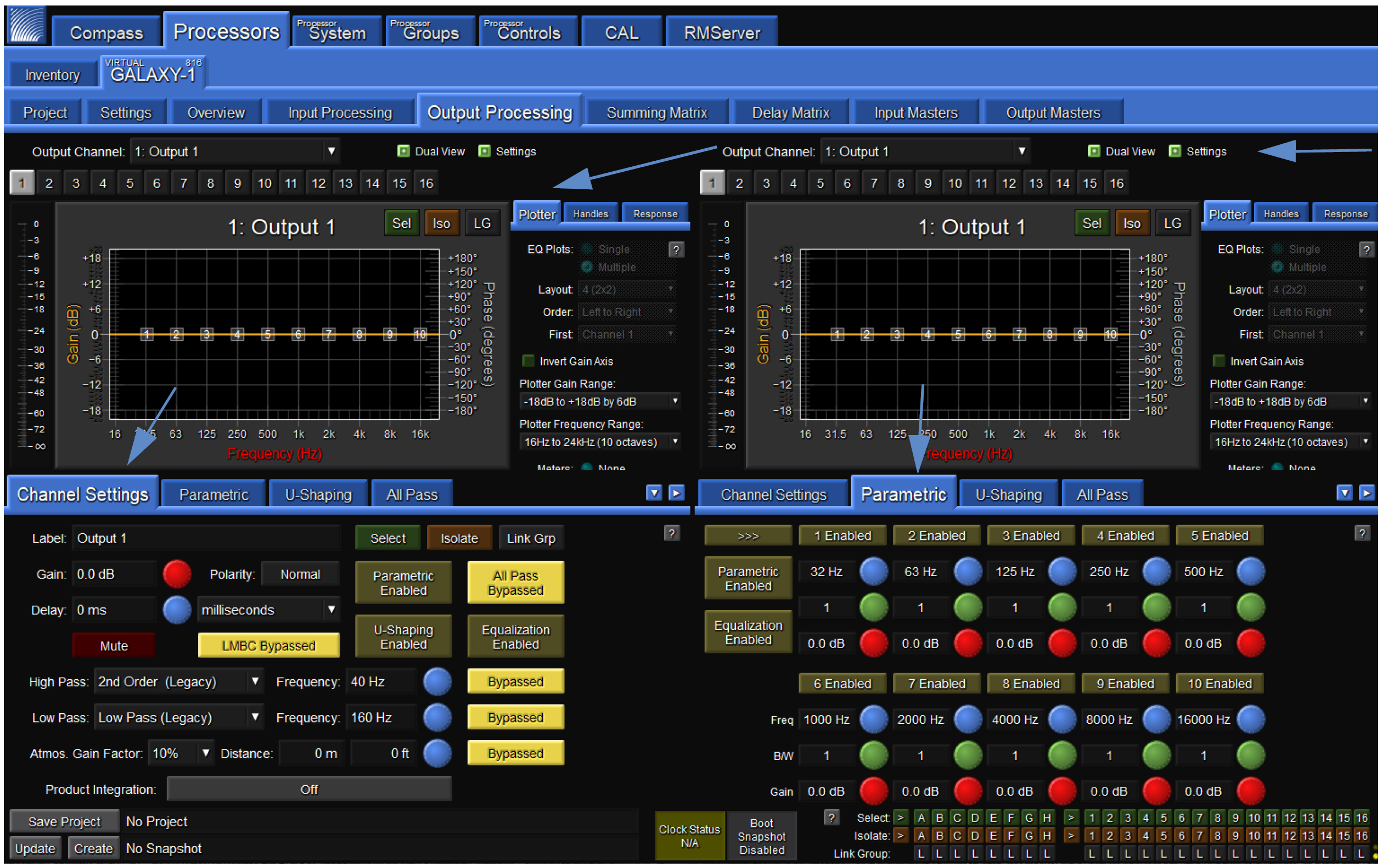
Processor > Output Processing > Channel Settings and Parametric tabs
Channel Settings tab (Output Processing tab)
Under the Channel Settingstab in Output Processing the user can set a Label, Gain value, Delay Value, Mute the Channel, and enable or bypass Parametric, U-Shaping, All Pass Filtering, and/or all EQ for a particular output channel. Select the Output Channel to control via the drop-down menu or individual alphabetic channel buttons above the plotter display.
The Label widget allows a user to enter a short text description of a Channel, Array Group, or Link Group. It is for informational purposes only.
The Gain widget lets the user increase or decrease the signal level by decibels (dB). The default assumes negative gain values. Entering any integer will result in the gain being set to the negative of that integer (e.g., “3” becomes -3 dB gain). (Default may be changed to positive gain values on the Compass Preferences tab.)
The Delay widget allows the user to add a delay (0–2000 ms) in various units to an output channel signal.
The Polarity button allows the user to change the polarity of each output channel from Normal (Pin 2 positive relative to Pin 3) to Reversed Polarity (Pin 3 positive relative to Pin 2).
Clicking the Mute button prevents any signal from being sent to the output of the channel.
Clicking the Select button causes this channel to be linked to other output channels that are also selected. Changes made to one selected channel will be made to all other selected channels of the same type (input or output) in a processor. These changes are relative by default. If channel 1 delay is 0 ms and channel 2 delay is 10 ms, when they are linked and channel 1 delay is changed to 5 ms, channel 2 delay will be 15 ms. Hold ALT while pressing ENTER for absolute values. To change default preference, change settings on this tab: Compass > GALAXY Preferences > Select, Isolate and Linking. Depending on the Global Linking Preferences, channels on other devices may be affected as well. Use Link Groups to quickly select or deselect multiple channels. Selected channels have a green background.
Use the Isolate button to temporarily isolate a channel from other channels to which it is linked. Isolating a channel will change its background color to amber.
Use the Link Groups button to edit multiple channels simultaneously. The Link Groups tab is also accessible from this pull-down menu. The Link Group to which a channel belongs is indicated by the number next to LG. Link Group index buttons are blue when enabled, yellow when bypassed, and gray when not in use. Channels in active link groups may have a blue background, depending on the Link Groups and Selects mode.
The LMBC Bypass button is a shortcut to the Low-Mid Beam Control tab (see Low-Mid Beam Control (LMBC)).
The Parametric EQ Bypass button allows the user to bypass Parametric EQ for an output channel without affecting the individual Parametric Band Bypass settings.
The U-Shaping Bypass button allows the user to bypass the U-Shaping EQ filter on a GALAXY processor output channel.
The EQ Bypass button allows the user to bypass all output Equalization filters while leaving filter-specific EQ bypass settings alone. Product Integration and Atmospheric Correction settings are not bypassed with this control.
The High Pass Filter widget allows the user to select a high-pass filter for the output channels from nine different options.
The Low Pass Filter widget allows the user to select a low-pass filter for the output channels from eight different options.
The Atmospheric Correction widget allows the user to apply equalization to the higher frequencies of a signal that might be affected by the natural environment. There are also widgets to enter the distance between the loudspeakers and the listening area. The attenuation of higher frequencies in the air varies with temperature, humidity, and altitude. There are Global Environment settings that allow a user to adjust for a particular natural environment (see Environment and Atmospheric correction).
The Product Integration button allows a user to turn on product integration for a particular channel (see ???).
Parametric (Output Processing tab)
Parametric controls may be set via a tab in the lower half of the Output Processing tab. Output Parametric EQ has 10 bands. Each band has four settings:
Bypass — Allows the user to bypass an individual parametric EQ band for that channel.
Frequency — Allows the user to adjust the central frequency of a parametric EQ band. The Frequency range is 10 Hz – 20 kHz. When entering a value, the Hz suffix is optional. A value can be entered in a number of ways. For example, 1500 Hz may be entered as 1.5 k, 1k5, and 1500.
Bandwidth — Sets the range of frequencies that are affected by band gain changes. The Bandwidth range is 0.1–2.0. When the Bandwidth is “1,” the handles span one octave. Setting it to “2” means the handles span two octaves.
Gain — Allows the user to adjust the gain of a parametric EQ band. The gain range is -18 dB to +18 dB.
U-shaping (Output Processing tab)
Controls for U-shaping are located within a tab also in the lower half of the Output Processing tab. The U-Shaping filter has five gain bands and four frequency breakpoints.
Each gain band may be individually set within the U-Shaping tab. The default assumes negative gain values (e.g., entering a “3” into the number box will result in a gain of -3 dB). This default setting may be changed to positive gain values via the Compass Preferences tab (Setting preferences).
Each of the four frequency breakpoints may also be set within the U-Shaping tab. The numerical input accepts a variety of format options. For example, 1500 Hz may be entered as 1.5 k, 1k5, and 1500. Entering “Hz” is optional.
The Slope settings are controlled via a pull-down menu. The two slopes on the left offer 6, 12, 18, 24, 30, 36, or 48 dB/octave. The two on the right do not have the 48 dB option.
The Bypass button allows the U-shaping to be bypassed without affecting the settings.
All Pass Filters tab (Output Processing tab)
The All Pass Filter tab, shown in the figure below, allows the user to engage up to three second-order all-pass filters, changing the phase relationship between various frequencies, while not altering the gain at any frequency. Adding all-pass filters is different than adding pure delay. While delay introduces the same amount of delay to all frequencies, all-pass filters introduce different amounts of delay at different frequencies. These filters are described by the frequency at which the phase shift is 180°.
Within this tab, the user may set the center frequency of the all-pass filter (frequency at which the phase shift crosses 180°) and the bandwidth Q of the filter. The lower the Q, the greater the bandwidth.
All Pass filters will alter the native phase response of the loudspeaker. This alteration may degrade performance and should only be used by experienced operators.
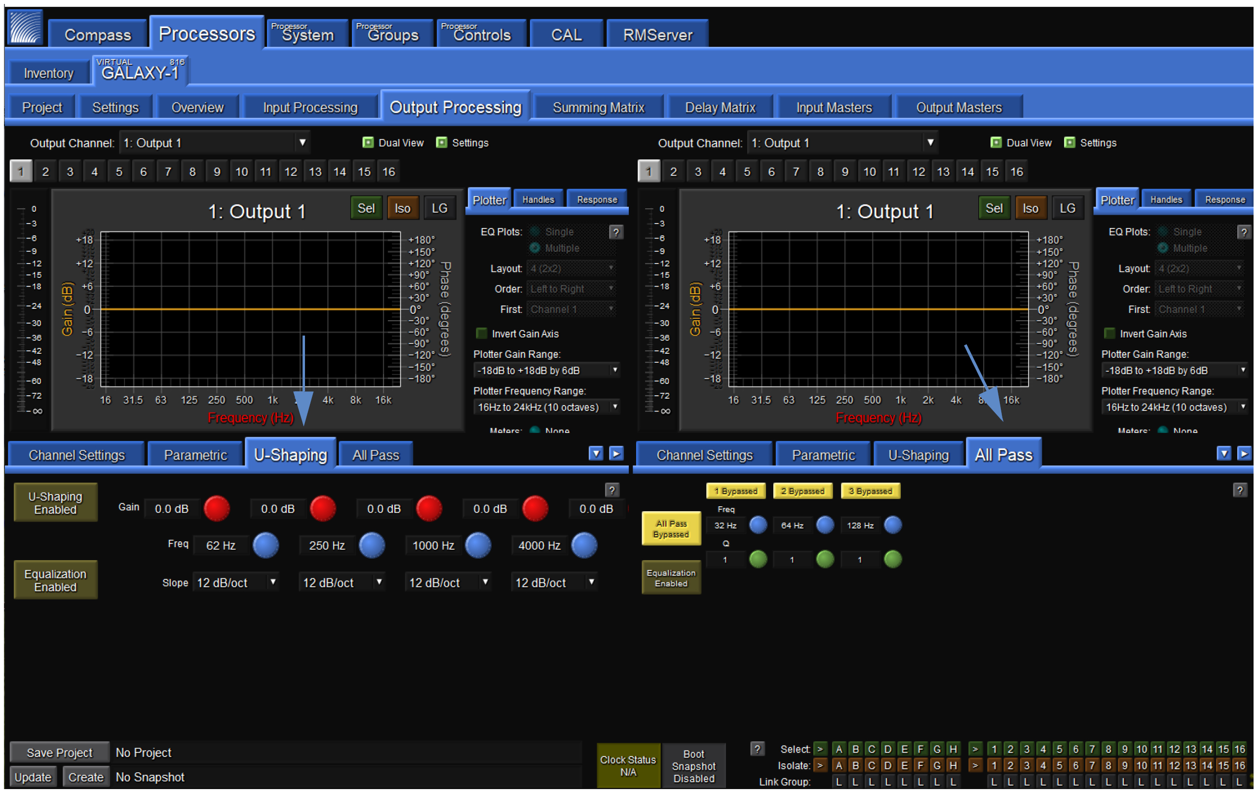
Processor > Output Processing > U-Shaping and All Pass tabs
Summing Matrix tab
The Summing Matrix, shown in the figure below, allows the user to route inputs to outputs within the processor. A maximum of 232 out of 512 connections between input channels and output channels (cross-points) can be made in the Summing Matrix tab. Each input channel can be level adjusted independently to individual output channels.
The Show Matrix Rows drop-down selects which inputs are displayed for routing. Inputs are the eight channels of processed inputs. Matrix In 9-16, 17-24, and 25-32 are only used for unprocessed AVB inputs.
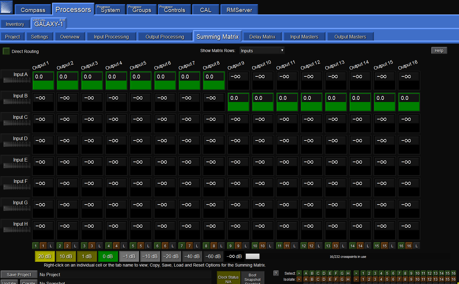
Processor > Summing Matrix tab
Matrix modes: Summing or Direct Routing
The Summing Matrix has two modes: Summing or Direct Routing. The mode is controllable via a select button at the top left of the Summing Matrix display window.
Summing is the default setting that allows the user to route multiple inputs to single or multiple outputs. When the Direct Routing button is selected, only one of the input channels may be assigned to one output.
Summing matrix operation
In both modes, the gain value for any matrix cross-point can be adjusted. The gain range is -90 dB to +20 dB, where -90 dB equals -infinity dB.
To select which group of 8 inputs to view at any one time, use the Show Matrix Rows drop-down menu above the matrix display in the middle of the screen.
The lower right-hand corner has a display indicating the number of cross-points in use. Of the 512 possible cross-points, 232 can be set simultaneously.
Color coding
Negative gain values scale from light gray to dark gray. Positive gain values scale from dark olive to light olive. There is a color legend below the matrix.
Delay Matrix tab
Delay times may be assigned to each matrix cross-point in the Delay Matrix tab shown in the figure below. Any delay values implemented here are independent of delay times included in the input or output processing blocks.
Each input channel can be assigned a time value independently to individual output channels.
To select which group of 8 inputs to view at any one time, use the Show Matrix Rows drop-down menu above the matrix display in the middle of the screen.
Delay can be bypassed by pressing the small button labeled “B” next to the delay time for each cross-point. Numeric delay values can be input for any matrix cross-point between 0–2000 ms.
The units for all channels may be set at the bottom right corner of this window.
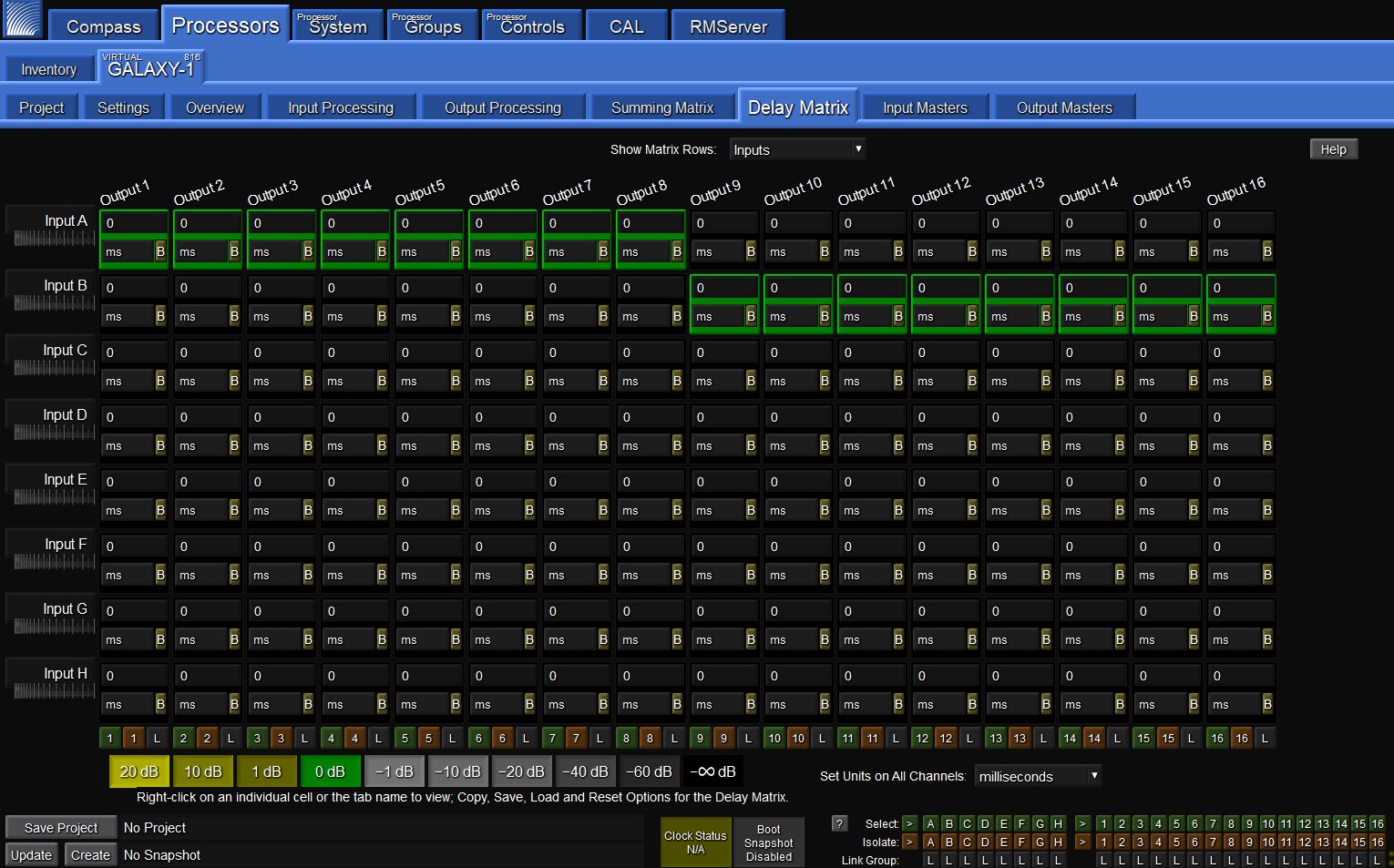
Processor > Delay Matrix tab
Input Masters tab
The Input Masters tab, shown in the figure below, provides fader controls to adjust the signal levels of the Inputs by decibels (dB).
Clicking above or below the handle results in single dB increments or decrements; clicking on a dB value to the right of the control will cause the gain to jump to that value.
There are also buttons to link channels of the same type by “Selecting” them, temporarily isolate a channel from other channels to which it is linked, or link groups to select multiple channels simultaneously.
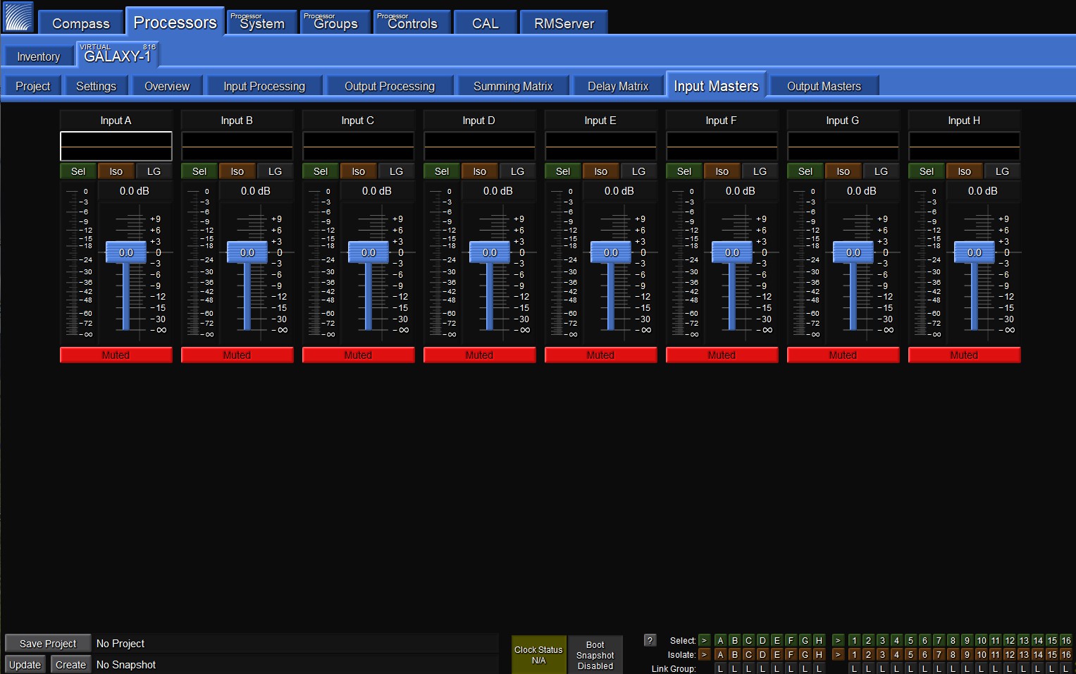 |
Processor > Input Masters tab
Output Masters tab
The Output Masters tab, shown in the figure below, provides fader controls for adjusting the signal levels of the Outputs by decibels (dB).
Clicking above or below the handle results in single dB increments or decrements; clicking on a dB value to the right of the control will cause the gain to jump to that value.
There are also buttons to link channels of the same type by “Selecting” them, temporarily isolate a channel from other channels to which it is linked, or link groups to select multiple channels simultaneously.
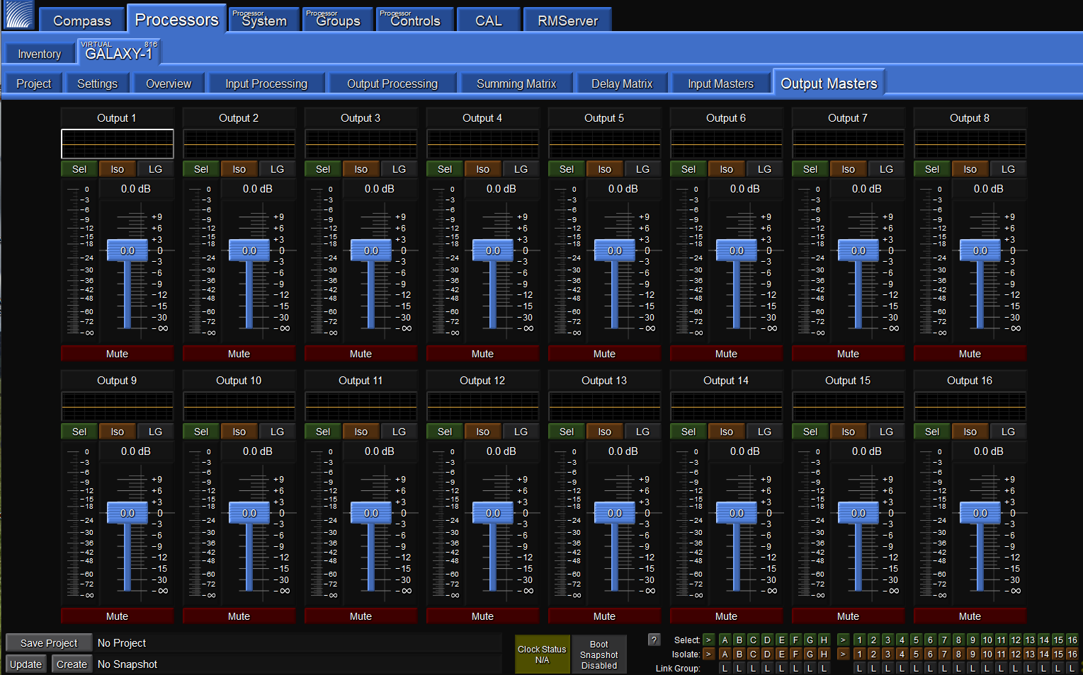
Processor > Output Masters tab
System tab
The System tab allows a user to view settings for multiple GALAXY processors simultaneously in one window. It is
read-only. Under the Inventory tab, select the processors to display by clicking on the small buttons to the far right of each device row, shown in the figure below. If blue, the settings for this device will display in the Processor System tab. If gray, they will be excluded. To enable viewing the same processor in two Compass application windows click the number 2 in the Window column, then click Show Secondary Processor Tabs Window.
Within the System tab display, there are controls for moving the displays to customize the view and pan/zoom capability.
Note
Any customized view created is not saved with the Compass Project.
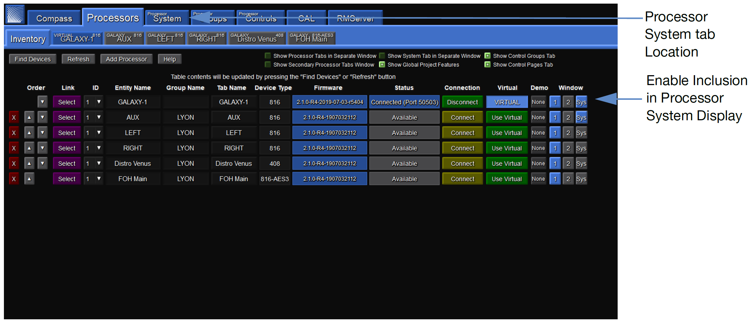
Enabling System View
Processor Groups tab
Users may choose individual channels from across multiple GALAXY devices to be a Group in the Processor Groups tab. Each Group will have a separate sub tab and as many groups as are desired may be made. Individual Groups or collections of multiple Groups can be saved and reloaded. The Group function allows users to gang inputs or outputs together from a single or multiple GALAXY processor(s) in a way that makes sense for a particular application. These Groups may then be controlled via the Processor Controls tab.
Processor Controls tab
Controls are added and assigned to Groups, moved and resized, and adjusted in the Processor Control tab. There are three modes: Layout, Configure, and Operate, which are selected in the upper-right corner. Choose Layout to add controls, gain, mute, etc., move and resize. Choose Configure to make Group selections for each Control. In Operate mode, the Control makes relative changes to all of the inputs or outputs assigned to the Group to which the Control is assigned. Controls that may be added are Delay, Gain, Mute, EQ Bypass, EQ Plot, Meter, and U-Shaping Gain. There is also an option to include a background image.