Settings view
Select a device from the Devices View.
Tap the Settings icon (highlighted in the top-left menu bar in the figure below). The Snapshot Settings are shown below.
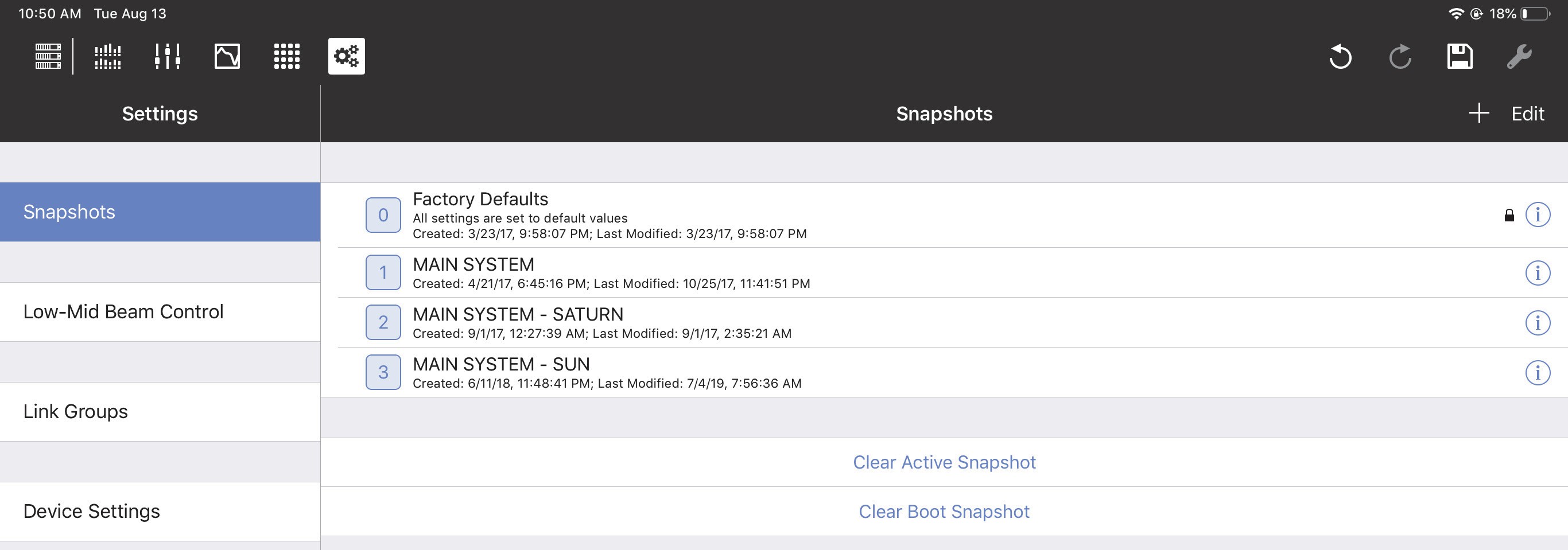
Settings View with Snapshots tab selected
Snapshots
A Snapshot contains all settings that configure a particular device. Each device has a:
Factory Default Snapshot: Includes typical settings to start with. It can be duplicated but not edited.
Boot Snapshot: Activated upon starting the device, and remains the Active Snapshot until another is loaded. If there is no Boot Snapshot, the device boots with its previous settings.
Active Snapshot: The Active Snapshot contains one instance of all GALAXY settings that are currently active in the GALAXY hardware.
Snapshot tab in Settings
Factory defaults
Tap Factory Defaults to recall the Factory Default settings.
Note
Enable AES3 output asynchronous sample rate converter
Create new snapshot
Tap Create New Snapshot to create a new Snapshot using this device’s current settings. This is now the Active Snapshot.
Clear active snapshot
Tap Clear Active Snapshot to clear the Active Snapshot. The device continues with its current settings and will use the Boot Snapshot (if one is assigned) next time it restarts.
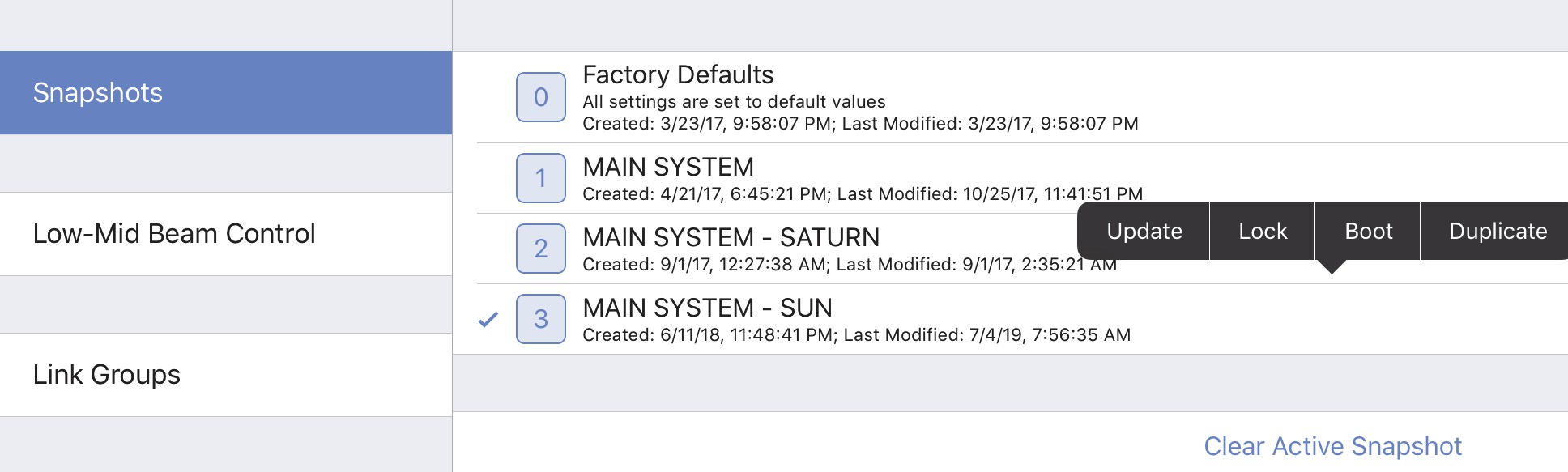
Snapshot assignment and editing options
In the figure above, MAIN SYSTEM - SUN is the Active Snapshot. Tap and hold any Snapshot. The following options are available (some states are context-sensitive and may appear inactive):
Update: Updates the Snapshot with the device’s current settings. The Factory Defaults Snapshot cannot be updated.
Lock or Unlock: Toggles the locked state of the Snapshot. When locked it, cannot be updated.
The Factory Defaults Snapshot cannot be unlocked.
Boot: Makes that Snapshot the Boot Snapshot.
Duplicate: Makes a copy of that Snapshot.
Note
There need not be an Active Snapshot. The device continues with its current settings
Clear boot snapshot
Tap Clear Boot Snapshot to remove it as the Boot Snapshot. A device without a Boot Snapshot restarts using its last settings before shutting down.
Low-mid beam control
Low Mid Beam Control (LMBC) is a tool that lets GALAXY users modify the natural vertical coverage of the low mid frequencies of a Meyer Sound line array to better match the high frequency coverage. Settings can be applied for up to four Arrays, each with up to 32 elements.
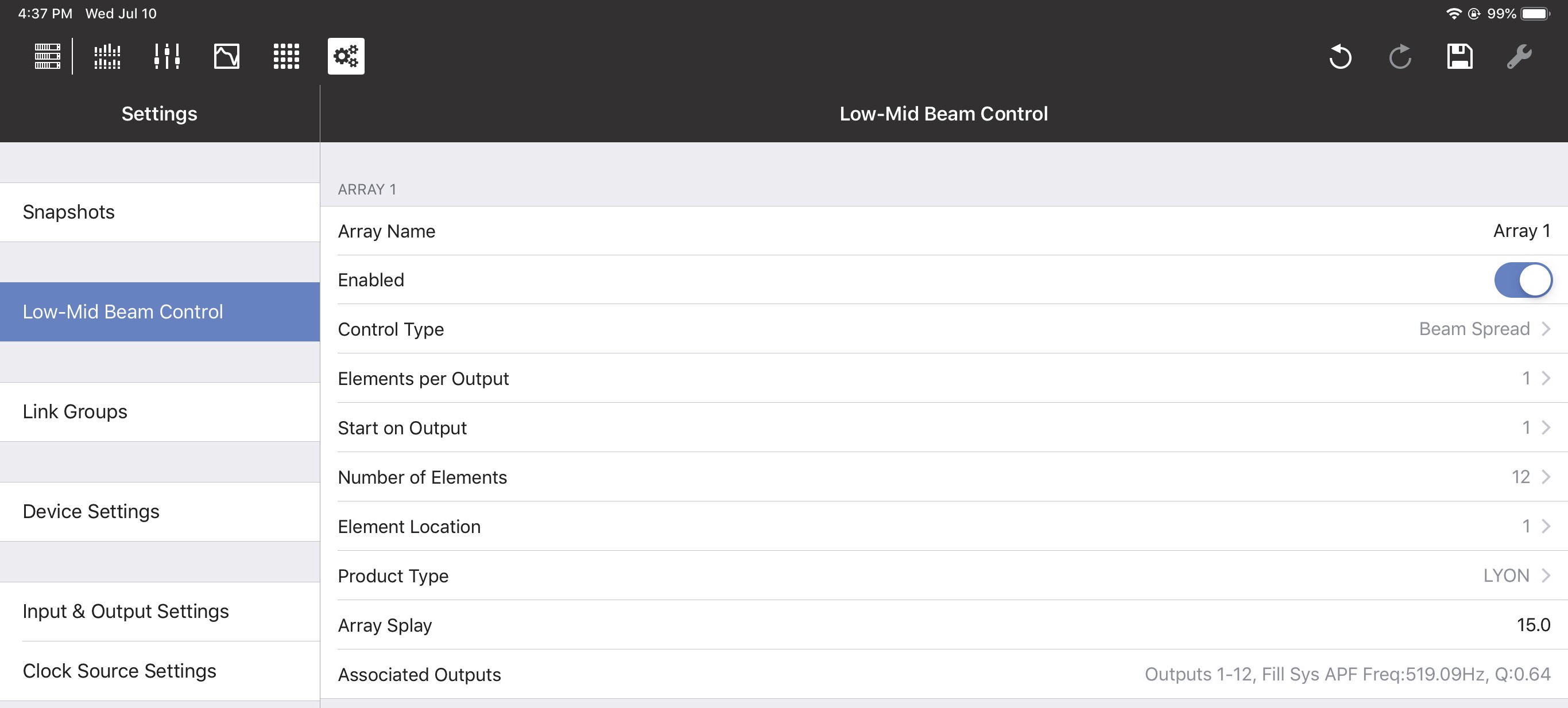
Low-Mid Beam Control tab
Low-mid beam control settings
Array Name: Lets you assign a name to the array (Flown Loudspeaker System). Enabled/Bypassed: This status button lets you enable or bypass LMBC for all affected channels. Control Type: The two options are Beam Spread and Steer Up.
Elements per Output: There can be one or two elements per output; this should match the physical connections in the array.
Start on Output: Selects the first output of the GALAXY processor where LMBC processing starts. Element 1 always starts at the top of the array.
Number of Elements: Sets the number of total elements in the array.
Element Location: Use this control when spanning multiple GALAXY processors if you have more than 16 elements that require more than 16 processor outputs.
For example, in an array with 22 elements, one element per output, and two processors:
Set the Number of Elements to 22 on both processors.
On the first processor, set Start On Output to 1, and set Element Location to 1.
On the second processor, set Start On Output to 1, and set Element Location to 17.
Product Type: Select the product type for this array from the list shown below:
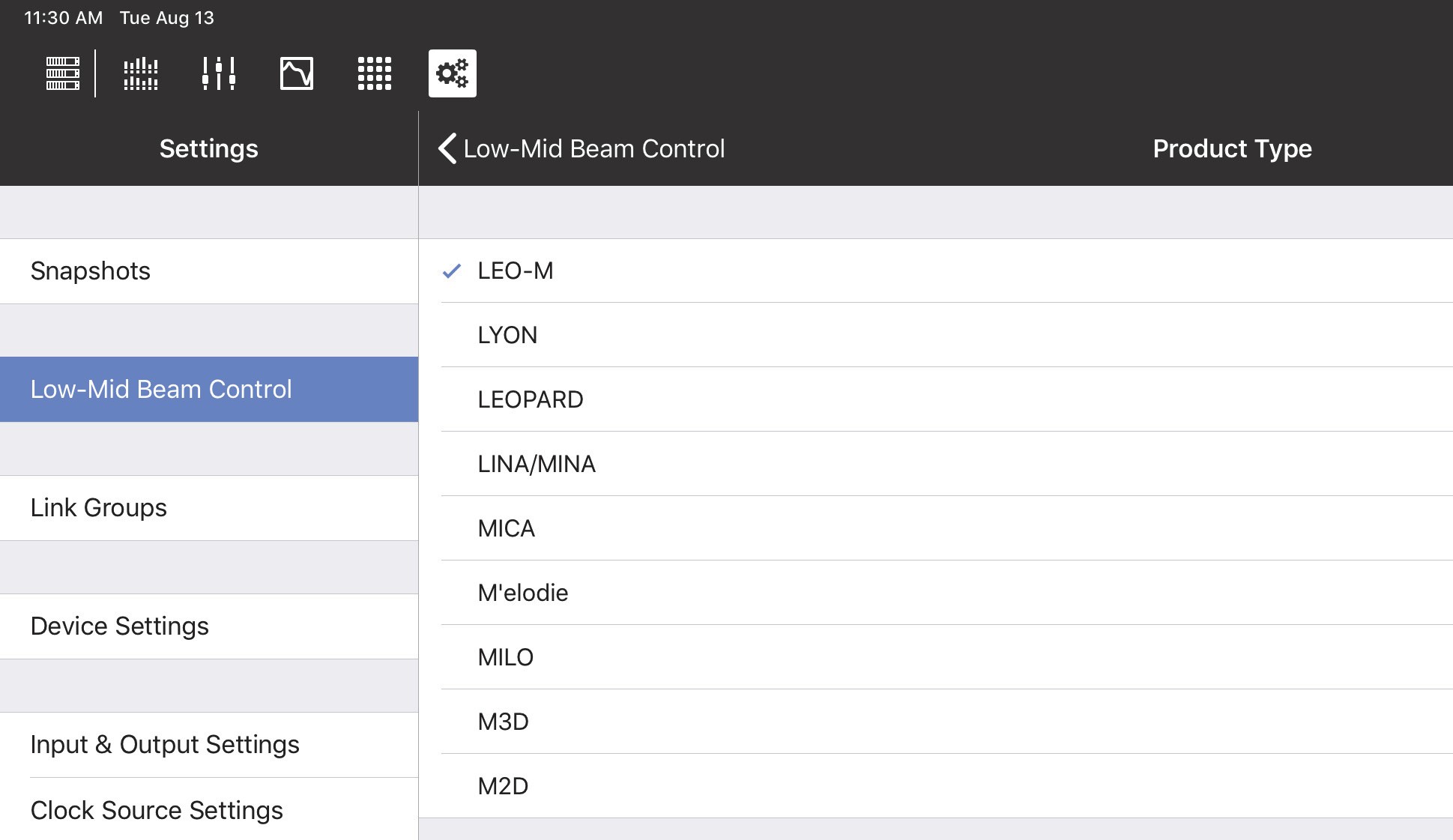
Product Types for LMBC
Array Splay: This is the sum total of the splay angles of the array.
Subtract the Rotation About Reference Point value from the Array Splay value shown at the bottom element of the Flown Loudspeaker System.
Enter the result in the Compass or Compass Go Array Splay column.
Set the splay angle between the top grid and the first element to 0º.
For example: If the MAPP Rotation About Reference Point = -2 and Array Splay = -56, then the LMBC
Array Splay = 54º.
Associated Outputs: This shows the device outputs in use with that LMBC array.
Note
If there is an error in the configuration, the Associated Outputs row turns red and its name changes to Error. A non-optimal configuration shows a warning in yellow.
Low-mid beam control operational tips
The following tips will help LMBC be more effective:
Signal drive lines must have correct polarity.
Apply LMBC before any other EQ.
Gain Tapering can make LMBC ineffective.
Do not treat array zones with different processing and/or gain below 1 kHz. For example, correct for low mid buildup with the same filters on the entire array, but correct for high frequency distance only above 1 kHz on individual zones.
Beam Spread is not optimal above 95º Array Splay.
Steer Up is not optimal above 45º Array Splay.
One array element per output is optimal.
Two array elements per output is maximum, and can only be used in an array with 12 or more elements.
Compass Software is designed to prevent invalid or non-optimal configurations.
LMBC is not designed to mix different product types in one array.
Set all speakers of the same type to the same Delay Integration pc setting.
When loudspeakers use separate outputs without LMBC, one all pass filter can be used to optimize align- ment with the LMBC outputs.
Link groups
Link Groups let you control multiple Inputs or Outputs simultaneously with one control. There are four Input Link Groups, and eight Output Link Groups.
Tap Link Group Name to enter a name for the Input or Output Link Group.
Input link groups (1–4)
Enable each Input Link Group you wish to control by sliding its button (Group 1, Group 2, etc.) to the right (it turns green). Then enable the Inputs (A–H) to include in that Input Link Group.
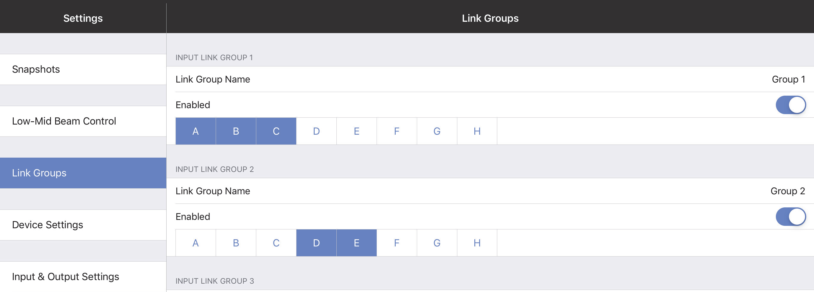
Input Link Groups from the Link Groups tab
Output Link groups (1–8)
Enable each Output Link Group you wish to control by sliding its button (Group 1, Group 2, etc.) to the right (it turns green). Then enable the Outputs (1–16) to include in that Output Link Group.
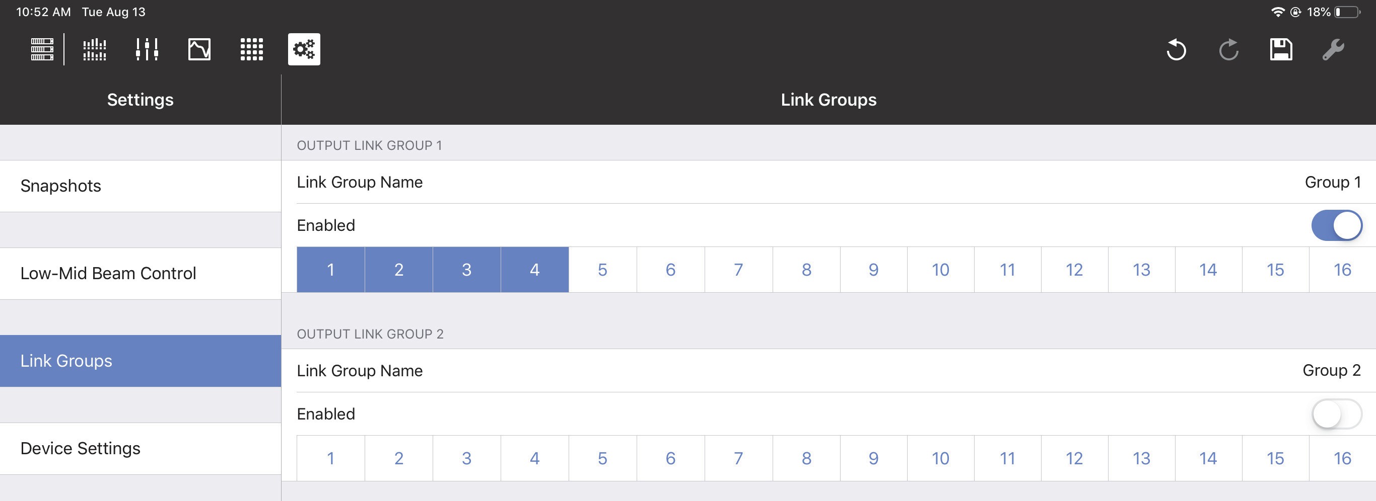
Output Link Groups from the Link Groups tab
Device settings
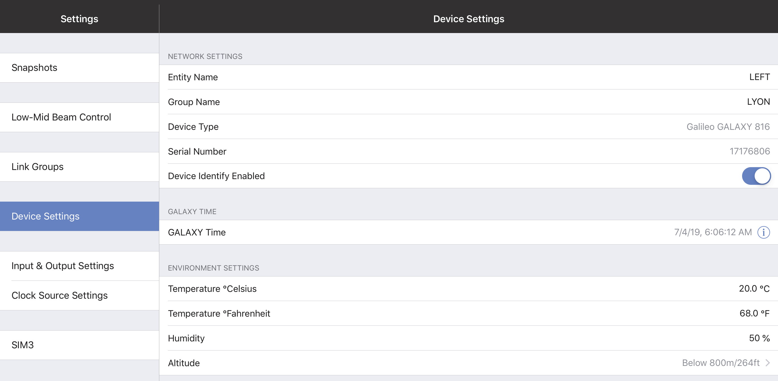
Device Settings tab
Network settings
These settings enable each device to uniquely identify itself on a network.
Device name
Initially, each Device receives an automatically generated name. To rename it, tap Device Name and use the onscreen keyboard.
Device group name
To assign a name to the Device Group, tap Device Group Name and use the onscreen keyboard.
Device type and serial number
These parameters are set at the Factory in each device and cannot be edited. Together, they uniquely identity each device (regardless of the user-assigned Device Name).
Device identity enabled
Slide the button to the right to cause this GALAXY device to identify itself by winking its rear panel Wink LED button and front panel display.
GALAXY time
The GALAXY Time can be edited using the fields shown by the figure below. Touch the date and time fields to set them manually.
Touch Set GALAXY Time to Local Time to set the time and date automatically.
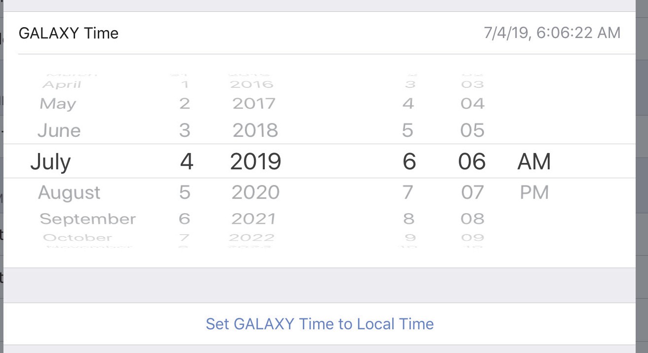
Setting the GALAXY Time
Environment settings
These values are used by the atmospheric correction algorithm (if enabled) and should be set to match the cur- rent operating environment.
Temperature Celsius
Temperature Fahrenheit
Humidity
Altitude
Input and output settings
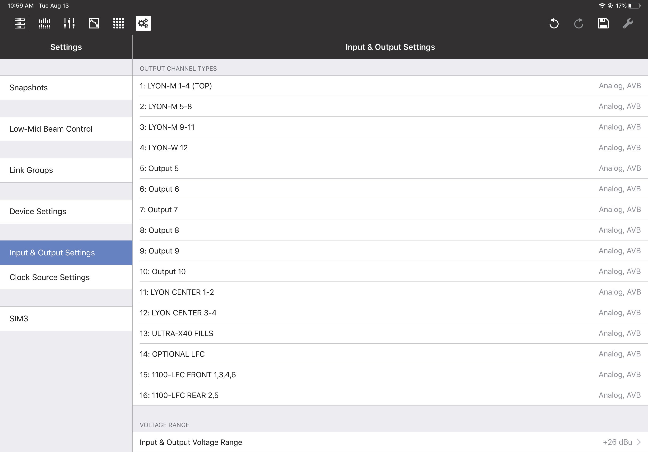
This section lets you specify the types of Inputs and Outputs you wish to use.

Input & Output Settings
Input & Output Settings
Default presentation time
Devices using the AVB I/O network periodically exchange timing information that allows both sides to precisely synchronize their time base reference clocks. This exchange of timing information allows an AVB listener to cal- culate the worst-case network transit time per stream, which is expressed as MSRP (Multiple Stream Reservation Protocol) Accumulated Latency. A network with one switch hop will typically have a smaller measured MSRP latency than one with several switch hops.
The Default Presentation Time lets the user obtain the lowest latency for AVB output streams in a given network topology without losing any audio samples.
Consider the following before choosing a Default Presentation Time setting:
The MSRP Accumulated Latency indicator displays the worst-case transit time through the network.
The Presentation Time Offset indicator is the maximum transit time handled by the AVB listener.
The Remaining Transit Time indicator is the time remaining between the packet reception and presentation time at the output.
Higher Default Presentation Time settings result in higher audio latency in the AVB streams.
Using a lower Default Presentation Time setting than the MSRP Accumulated Latency will lose audio samples, resulting in lower-quality audio. Therefore, always set the Default Presentation Time value higher than the MSRP. Include a margin of error to support possible changes to the network topology or bandwidth.
Note
To synchronize your local AES or analog input(s) to an incoming AVB stream with a given presentation time, add the appropriate amount of input delay to the desired non-AVB inputs. For example, if the AVB source’s default presentation time is 2 ms, set the input delay on each local device AES or analog input to 2 ms.
Input channel types
Input Types can be Analog, AES3, or AVB.
When the AES3 input and the GALAXY’s sample rate are the same, you can disable Enable Asynchronous Sample Rate Converter to reduce the latency introduced by the clock recovery. When disabled, you must use another method to synchronize the AES3 input with the GALAXY’s clock signal.
Input Channel Types
AVB connections
An AVB Stream functions much like an analog multi-cable. Each stream can vary in number of channels and format, similar to AES3 and standard analog multi-cables. The difference is that many audio streams can flow down a single Ethernet cable.
Unlike traditional multi-cables, AVB streams do not stay connected when the audio devices are turned off. An AVB software controller creates and maintains these connections running on a computer attached to the net- work or inside one of the audio devices being controlled. An AVB controller in the audio device will maintain persistent connections and remake connections after power cycle or other interruptions like unplugging an Ethernet link.
Each GALAXY has a built-in AVB controller. If GALAXY B’s inputs are subscribed to GALAXY A’s outputs for the first time using Compass software, GALAXY B’s AVB controller will attempt to remake that connection in case of any interruption.
GALAXY AVB streams are 24-bit/96 kHz 8-channel AAF packet format. AAF supports the transport of multi- channel 24-bit linear audio. Since GALAXY inputs can choose up to eight individual AVB channels from up to eight different streams, it is possible to send up to 8 eight-channel streams (64 channels) into the unit. How- ever, only eight of them are available for input processing. There are 24 additional AVB inputs available into the Gain, Delay, and Router matrices without input processing (see figure below).
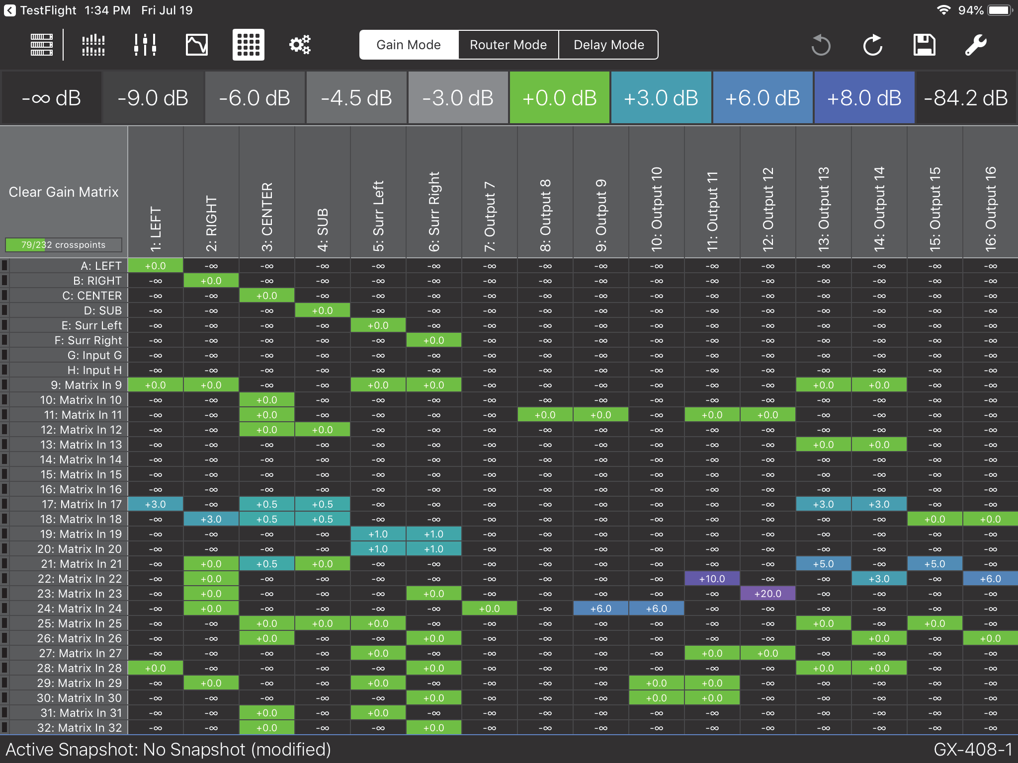
Expanded Matrix Inputs
GALAXY outputs use two AAF formatted streams: Outputs 1–8 are available in the first 8-channel stream, out- puts 9–16 are available in the second 8-channel stream. If no units have subscribed to these streams, the GALAXY will stop transmitting altogether. The analog outputs are always active.
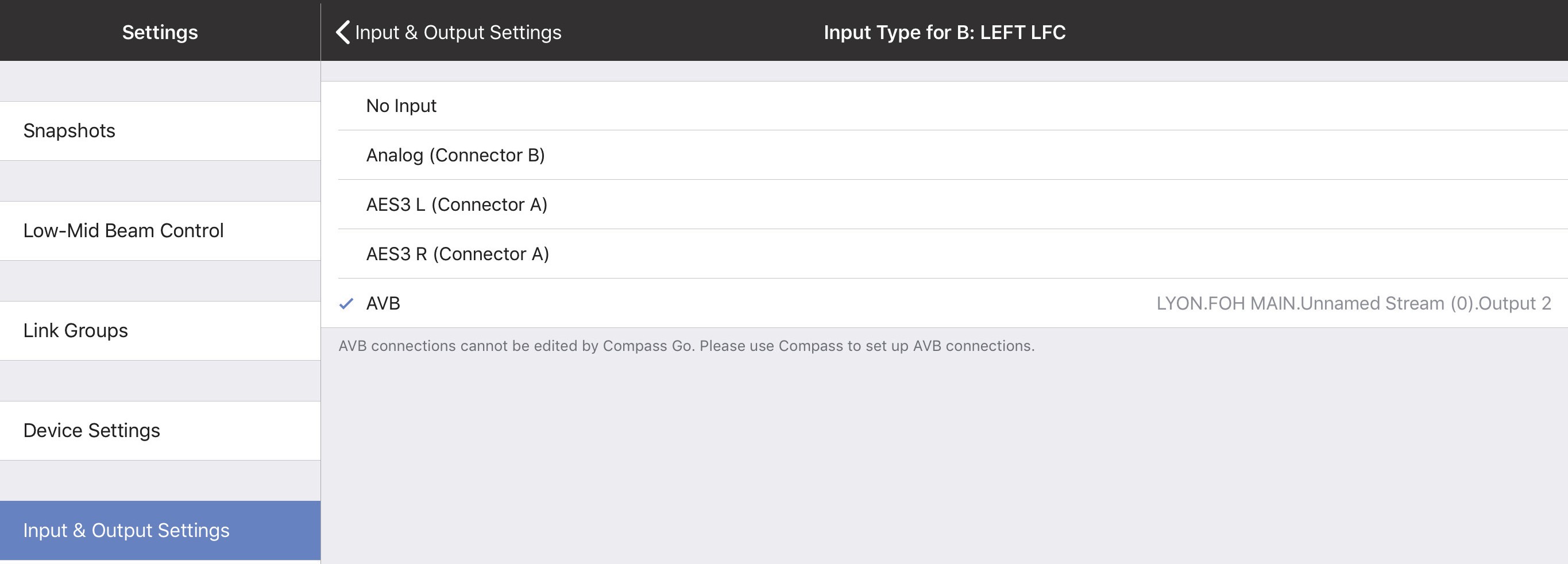
Network digital source signals can be connected to the AVB/Network port connectors (labeled 1 and 2) on the GALAXY rear panel. Standard AM824 eight-channel AVB streams are supported (24 bit, 48/96 kHz). The AVB Controller Mode can be set to External or Internal. AVB Stream Information can be viewed by selecting the status indicator next Input Channel Type if AVB is used for a given channel, as shown in the figure below.
AVB Connections cannot be edited by Compass Go. Use Compass Control Software to setup AVB connections. AVB Stream Information can be viewed by selecting the status indicator next to the Input Channel Type if AVB is used for a given channel.
Compass Control software is available at: https://meyersound.com/product/compass/
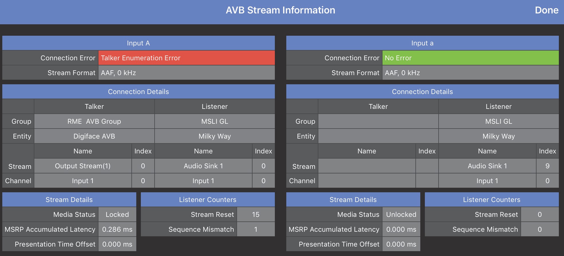
AVB Stream Information window
The figure below shows the Device Group, Device, available Stream, and Channel (to the right of the selected AVB) for a configuration using the Internal AVB Controller Mode in Compass Control Software. See Compass Control Software Help for more details.
The figure below shows a completed AVB connection.
Results of an Internal AVB Controller Mode configuration using Compass Software
Input and output voltage range
The Input & Output Voltage Range can be set to +26 dBu or +16 dBu. To toggle the voltage range, tap the current value, select the other setting, and tap Done.
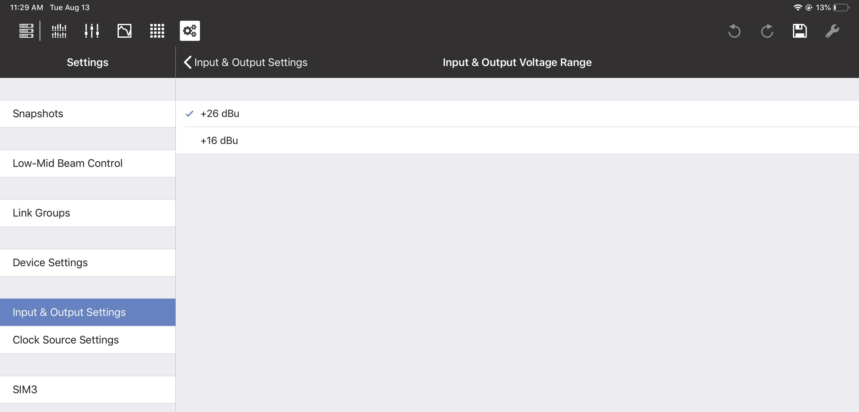
Input & Output Voltage Range
The Input & Output Voltage Range can be set for a different range of Input/Outputs on each GALAXY device:
GALAXY 816: Input/Outputs 1-16
The GALAXY 816-AES: Input/Outputs 9-16
The GALAXY 408: Input/Outputs 1-8
Clock source settings
These settings control how this device is synchronized within its system.
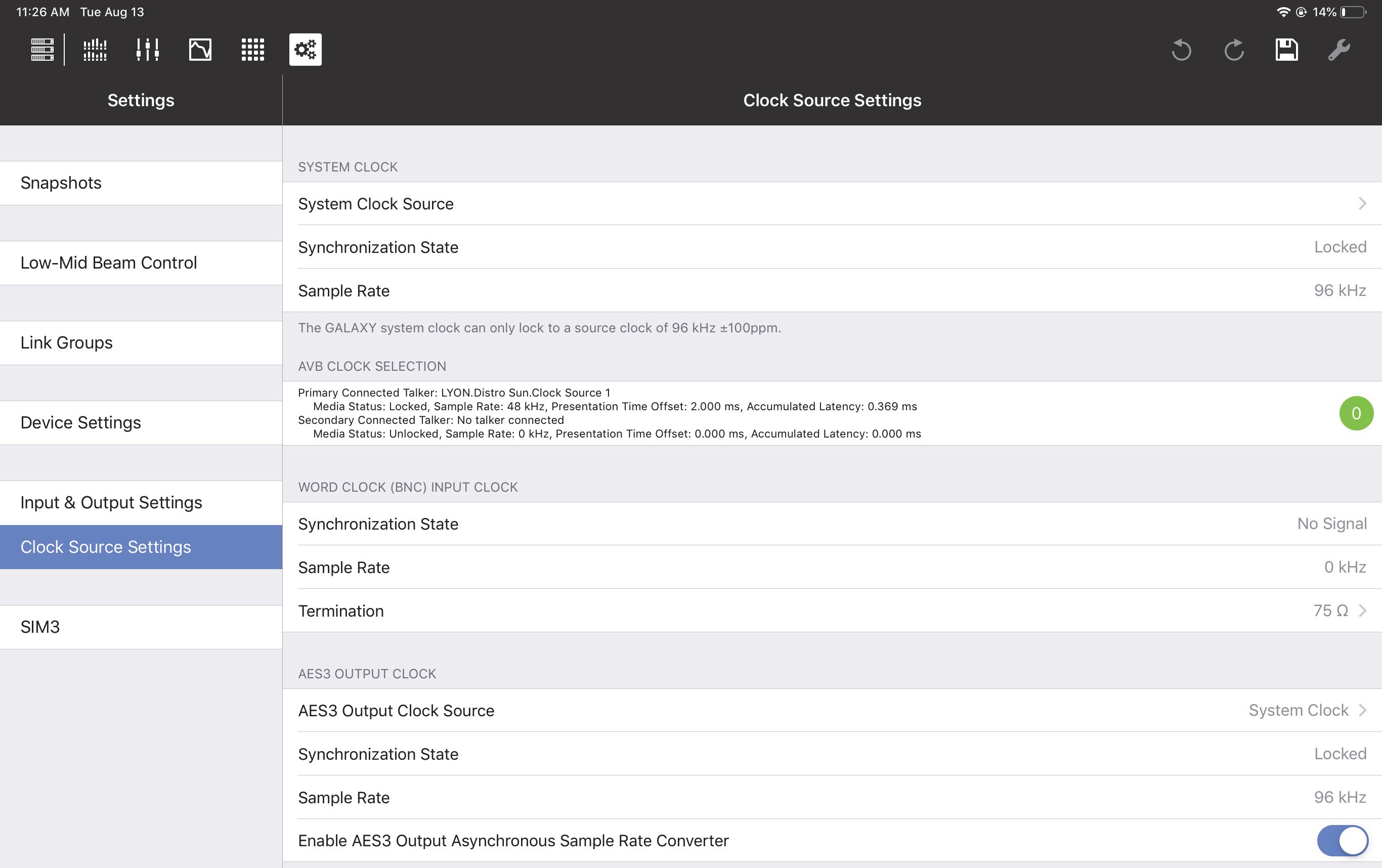
Clock Source Settings tab
System clock source
The System Clock Source can be set to Internal, AES3, AVB (if AVB connections have been established), or
Word Clock (BNC),
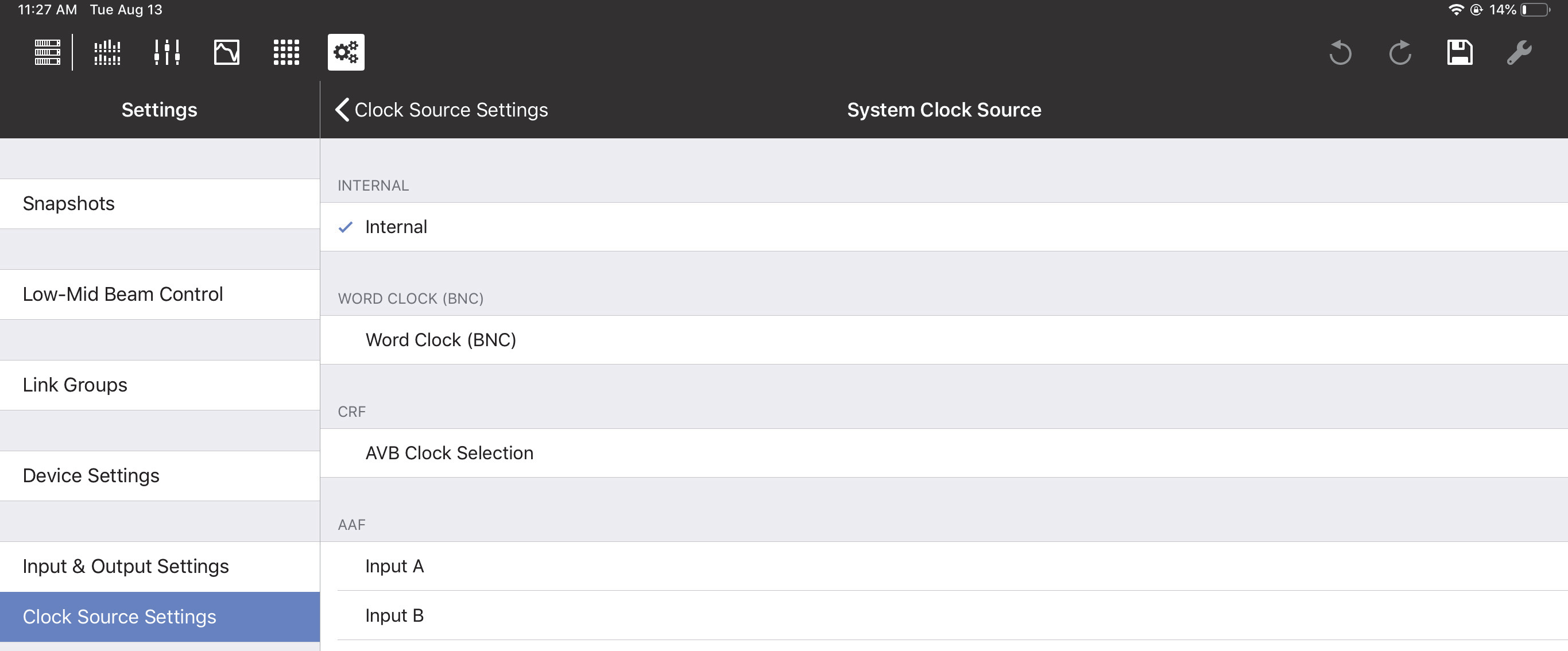
System Clock Source Settings
If using AES3:
Specify which Input to use as the System Clock Source.
The input and output system clocks may be different.
Note
If each device uses its own internal clock source, they will not stay synchronized.
Synchronization state
This field shows the status of the System Clock assignment: locked, unlocked, or no signal.
Sample rate
Sample Rate is set elsewhere and cannot be changed here.
AES3 output clock
This setting controls the synchronization of AES3 outputs.
AES3 output clock source
The AES3 Output Clock Source can be set to System Clock, AES3, or Word Clock (BNC). If using AES3, specify which Input to use as the Clock Source.
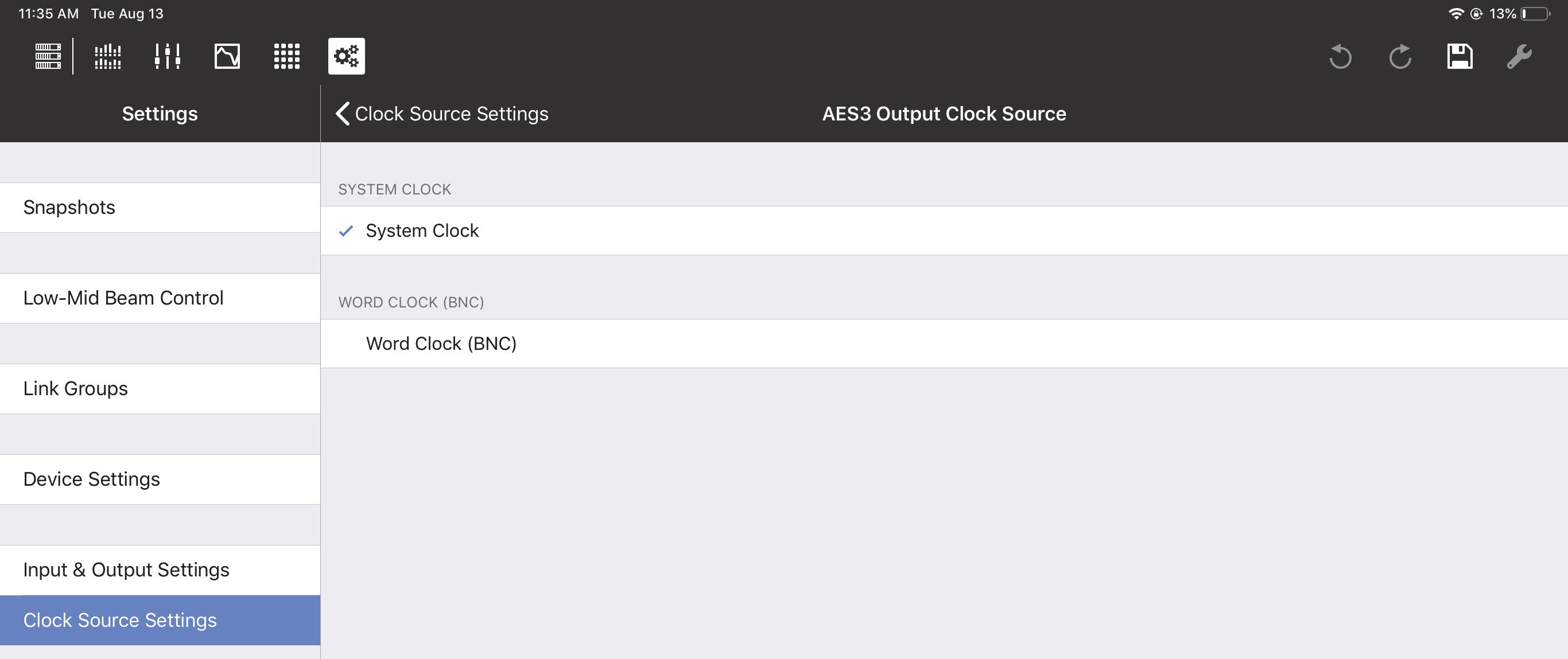
Setting the AES3 Output Clock Source
Synchronization state
This field shows the status of the System Clock Source assignment: locked, unlocked, or no signal.
Sample rate
Sample Rate is set elsewhere and cannot be changed here.
Enable AES3 output asynchronous sample rate converter
Slide the button to the right to enable the AES3 Output Asynchronous Sample Rate Converter.
SIM3
The Meyer Sound SIM3 Measurement and Correction System can be interfaced with GALAXY devices.
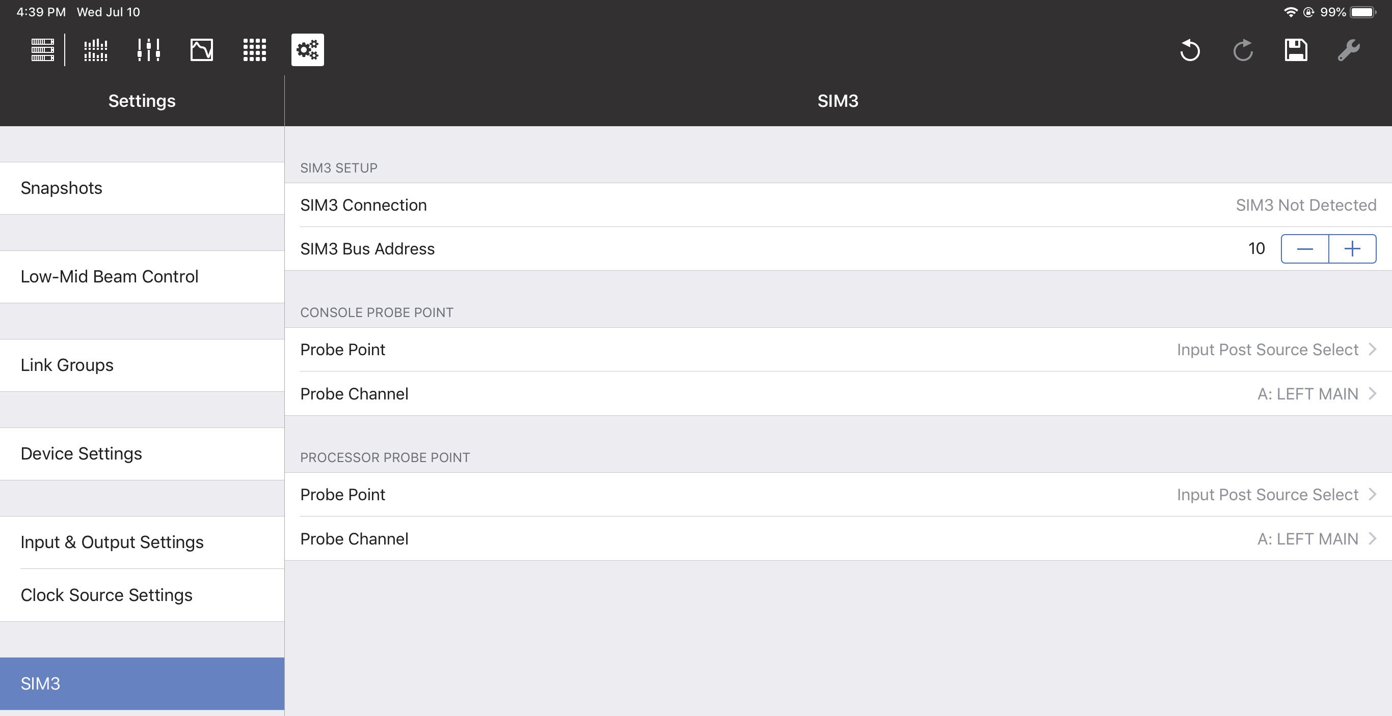
SIM3 options
SIM3 setup
Consult the SIM3 machine to determine its Bus address. In Compass Go, enter it in the SIM3 Bus Address field using the +/- buttons.
The SIM3 Connection field should now display SIM3 Detected.
Note
SIM3 can also be interfaced using the AVB network. Contact Meyer Sound Technical Sup-port for help with SIM3 (page 5).
Console and processor probe point and channel
The Console Probe Point, Console Probe Channel, Processor Probe Point, and Processor Probe Channel can be set to the following options:
Input Post Source Select
Input Post Processing
Output Post Matrix
Output Post EQ
Output Post Processing
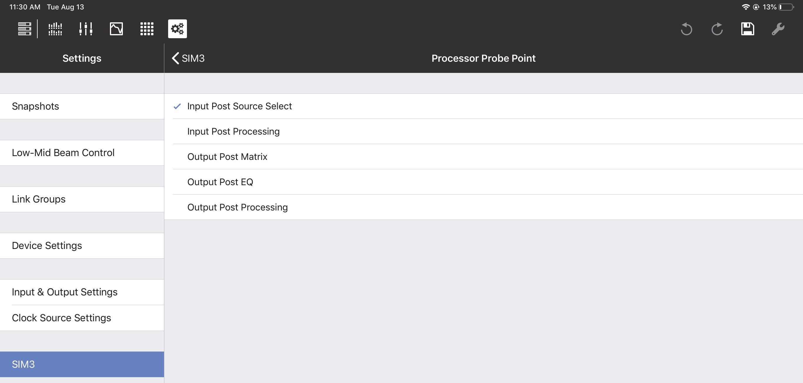
SIM3 Processor Probe options
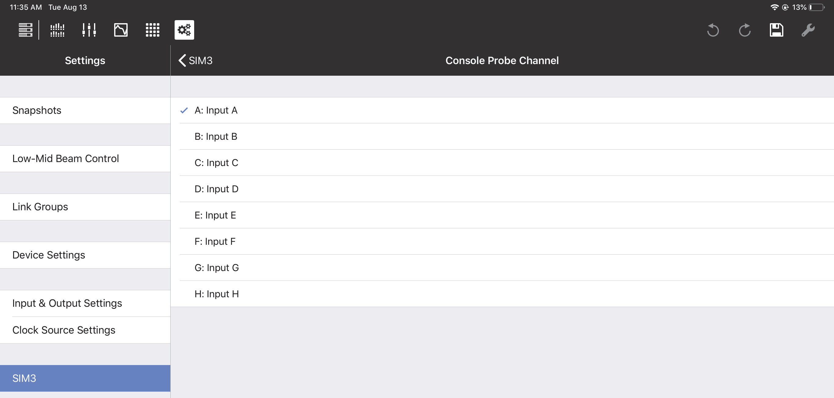
SIM3 Console Probe Channel options
Global controls
The Global Controls are at the top-right of each view.
Tools
The wrench icon accesses the Tools options, which differ for each view. See the end of the Overview, I/O, EQ, and Matrix View sections for details. Note that the Tools icon is dim and not available from the Settings View.
Save settings
The disk icon opens a dialog to update, create, and recall Snapshots.
Tap the disk icon to open the following dialog:
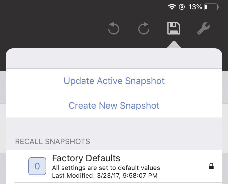
Disk icon with Snapshot options
Do one of the following:
Tap Update Active Snapshot to update the current Snapshot.
- OR -
Tap Create New Snapshot to create and name a new Snapshot.
- OR -
Tap a Snapshot in the RECALL SNAPSHOTS column to restore its saved settings.
Undo/redo editing
The most recent editing operation can be undone/redone with the standard circular controls.