Getting started
MAPP 3D Installation and Activation
Below are the steps to download, install, and activate MAPP 3D. Loudspeaker data is not included with the installation file. Please find the link at the bottom of this page or use the menu above (START > UPDATES) for loudspeaker data download instructions.
Download
Visit meyersound.com, login, or create an account.
Visit meyersound.com/product/mapp-3d or from meyersound.com, click PRODUCTS in the page menu, scroll down, and select MAPP 3D to open the product page.
From the MAPP 3D product page, click ACCOUNT in the page menu at the top.
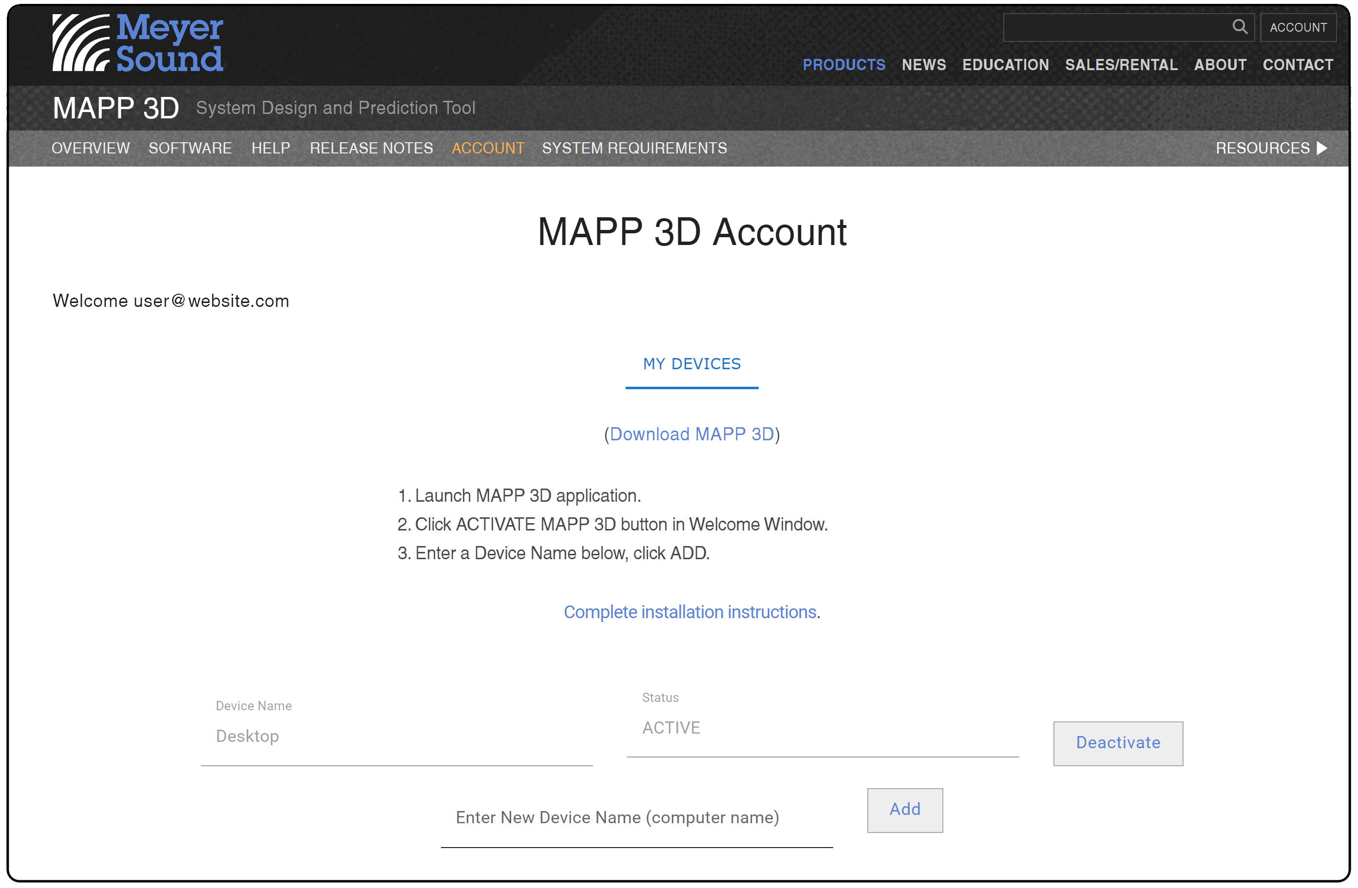
MAPP 3D Account Page, Download MAPP 3D

Locate, then launch the MAPP 3D_1.x.x.dmg application installer.
Read and click AGREE to the terms of the end user license agreement.

Read And Agree To End User Agreement
Drag the application to the Applications folder.

Drag App to Applications Folder
Click the arrow/line button to eject MAPP3D.

Eject MAPP 3D
In the /Applications folder, locate MAPP3D-Release and click once. Select the MAPP 3D.app to launch the application.
Note
There may be a security warning when launching the application for the first time. This is normal, please click through.

Launch MAPP 3D.app

Double-click the MSI application installation file.
Click NEXT to start installation.

Start Install? – Click NEXT
Read and click AGREE to terms of the end user license agreement.

Select Installation Destination
Use the default location or select another location to install the application.

Select Installation Destination
Select affirmative options in each of the dialogs.

Click Affirmative Choices for All Dialogs
Launch the application from Explorer or the desktop shortcut.

Launch MAPP 3D Application From Explorer or Desktop Shortcut
Activate MAPP 3D
When the application opens, the Welcome to MAPP 3D pop-up opens.
Click the ACTIVATE MAPP 3D button.
Note
Opens web page: https://meyersound.com/product/mapp-3d/#account

Click ACTIVATE MAPP 3D Button
Select the MY DEVICES tab. Enter a user-defined NEW DEVICE NAME and click the ADD button.

Enter New Device Name, Click ADD
Hover your mouse over the Reservation Code and left-click to copy the Reservation Code to the clipboard (not the usual right-click or CMD-C/CTRL-C to copy).

Click to Copy Registration Code
Return to the MAPP 3D application with the open User Registration pop-up.

Return to the MAPP 3D Application
Fill the fields of the User Registration window:
Enter the same email address used to login to the web site
Paste Reservation code
Enter the associated Device Name
Click REGISTER

MAPP 3D – Enter the Username, Reservation Code, and Device Name, Click Register
Important
Loudspeaker data is not included in the application. Please follow the link at the bottom of this page for instructions to download the loudspeaker data.
MAPP 3D must be opened once every 30 days while the host computer is connected to the Internet to validate the application authorization.
When completed, the Successful Activation pop-up window will open (below). If this confirmation is not displayed, please visit www.meyersound.com/contact, and select Technical Support.

Registration Confirmation
Click OK to close the Successfully Activated pop-up. The MAPP 3D Software Update window automatically opens. Select models of loudspeakers or select INSTALL ALL to download loudspeaker data sets. See the Application and Loudspeaker Data Updates page for further information.
Managing devices
To activate or deactivate the MAPP 3D application, open the Welcome pop-up in MAPP 3D by launching the application or closing all open projects. Click the two-state button, Deactivate MAPP 3D / Activate MAPP 3D. When the application is deactivated, click the Activate MAPP 3D, which opens the User Registration dialog in MAPP 3D and the MAPP 3D Account web page. Use the information from the MAPP 3D Account web page to fill the User Registration dialog in MAPP 3D.
Two devices can be activated for each MAPP 3D account. From the application, select HELP > MANAGE MAPP 3D ACCOUNT to open MAPP 3D Account web page. Click MY DEVICES. Add and remove devices as desired.

Account Management – Add / Remove Devices, Maximum Two Per User
Update application, help, and loudspeaker data
The MAPP 3D application does not include loudspeaker data with the installation file. This approach allows new data sets to be added without installing a new version of the application. Below are the steps to download loudspeaker data.
MAPP 3D Update
Currently, MAPP 3D application updates are made through a distributed application installation file. In the future, MAPP 3D will offer application updates within the software.
Online Help Update
Currently, MAPP 3D Help is available while online. In the future, MAPP 3D Help will be made available for download.
Loudspeaker Data Update
If this is the first launch of the application after installation, click CREATE EMPTY PROJECT. Then, in the PROJECT PROPERTIESdialog, click OK.
Navigate to HELP > CHECK FOR UPDATES

Software Update – Update The Application, Help, And Manage Loudspeaker Data
Select INSTALL from the drop-downs for each Speaker Type that may be used.
Note
Select RIGGING from the top of the Speaker Type list to download all rigging elements.

Use The Drop-Down Menus To Select An Action For Each Loudspeaker Type
Click APPLY to make the selected changes; the download will start.
Click DONE to close the Update window.
Check for updates
MAPP 3D Update
Currently, MAPP 3D application updates are made through a distributed application installation file. In the future, MAPP 3D will offer application updates within the software.
Online Help Update
Currently, MAPP 3D Help is available while online. In the future, MAPP 3D Help will be made available for download.
Loudspeaker Data Update
If this is the first launch of the application after installation, click CREATE EMPTY PROJECT. Then, in the PROJECT PROPERTIES dialog, click OK.
Navigate to HELP > CHECK FOR UPDATES
Select INSTALL from the drop-downs for each Speaker Type that may be used.
Note
Select RIGGING from the top of the Speaker Type list to download all rigging elements.

Use The Drop-Down Menus To Select An Action For Each Loudspeaker Type
Click APPLY to make the selected changes; the download will start.
Click DONE to close the Update window.
MAPP XT user reference
This information is intended to identify the differences between MAPP 3D and XT, making your first uses of MAPP 3D more efficient and productive, and less frustrating.
General differences
No Internet connection is needed to predict results. MAPP 3D is ‘offline,’ meaning there is no client/server connection utilized for prediction.
The loudspeaker and rigging data is not included in the application installation file. Open HELP > CHECK FOR UPDATES, select Rigging and the desired loudspeaker models for download. This prevents having to install a new version of the application when a new loudspeaker model is available.
MAPP 3D will need to validate the application authorization once every 30 days while the host computer is connected to the Internet.
Note
MAPP 3D projects are saved with the file extension: .mapp
Application operations
Double-click tabs to un-dock, and double-click window header to re-doc.
When entering values or coordinates, select a value (click), and type a new value or press up/down keyboard arrows.
When naming objects and layers, use a capitalization scheme to easily identify object types, e.g., LOUDSPEAKERS, Geometry, microphones.
Model view
In the Model View tab, right-click to open contextual or pop-up menu.
Pan model: hold SHIFT, click-hold, and move mouse.
Orbit model: hold SPACE, click-hold, and move mouse.
Zoom with mouse wheel or Tools.
Zoom to Extents, use this tool button:
 .
.
Venue drawing
See BUILD > NAVIGATION in the site menu above regarding the Coordinate System used in the 3D model space
See BUILD > ADD PRIMITIVES and QUICK DRAW VENUE in the site menu above for information about drawing venues
Edit the properties of geometry in the Properties tab or Object Settings tab
When adding Primitives, select a non-isometric or “flat” view (Top, Left, Right, Front, or Rear) to add geometry on an axis with a zero value. This is illustrated below:

To Add Primitive Flat on an Axis, Add Primitive in Flat Viewport
Predictions in Model View
Instead of visualizing sound pressure in air, Primitives are added and selected for prediction. These Prediction Planes can be offset from the geometry to represent ear height.
The pressure plot colors can represent SPL (new) or Attenuation (like MAPP XT); select via the FILE > PROJECT SETTINGS > SPL tab. In SPL mode: the values are average SPL (not peak) and are only for the selected frequency range, e.g., one octave, 4kHz—see MEASUREMENT VIEW tab, HEADROOM tab for broadband SPL.
If the prediction results are plotted as mostly white or mostly black, adjust the SPL Maximum Value or Minimum Range (FILE > PROJECT SETTINGS > SPL tab).
If an object can not be selected or edited, ensure its layer is unlocked.
To visualize sound in air (like MAPP XT), add geometry parallel to the Z-axis, on-axis to a loudspeaker or array.

Model View – Vertical Prediction Plane
Layers
Layers are managed in the TOOLS > LAYER MANAGEMENT window.
Use a capitalization scheme to easily identify layers that have different object types, e.g., LOUDSPEAKERS, Geometry, microphones.
Processors
Use INSERT > SIGNAL PROCESSOR to add processors. Processors are edited and managed in the PROCESSOR SETTINGS tab.
Editing
Use the Express Settings tab to edit common properties for geometry, loudspeakers, processors, and microphones.
Use the Properties tab to edit common properties for geometry.
Import
DXF and SKP (SketchUp) formats—one of each format can be imported into a project (FILE > IMPORT).
Both file types import with layers accessible for show/hide and locking, see BUILD > IMPORT DRAWINGS in the site menu above.
Special
LMBC settings are accessed in PROCESSOR SETTINGS tab, LOW-MID BEAM CONTROL tab.
The Auto-Splay tool is accessed in TOOLS > AUTO-SPLAY.
Connect to Galileo GALAXY processors via TOOLS > SIGNAL PROCESSOR MANAGEMENT; push or pull processor settings when connecting.
Reference material
Keyboard Shortcuts (also under the MORE menu at top of this page)
FAQ
Start a MAPP 3D project
Templates
Templates are selected from the Welcome Window or application menu. Click TEMPLATES, select template file, then click CHOOSE. When the Welcome Window is closed, use the FILE > OPEN TEMPLATE menu to open templates.
Templates are provided as examples to easily explore the functions of MAPP 3D. We anticipate adding additional templates to satisfy user requests and needs.

Welcome Window, Select Template
System design project workflow
MAPP 3D can be used in a variety of ways. When starting a system design, these are the steps usually taken:
Gather preliminary project information
Create new project
Enter project properties
Save new project
Make application preference choices
Import drawing(s)
Create additional layers
Add geometry
Add processors
Add loudspeakers
Add microphones
Check and optimize performance
Save project
Export screenshots and reports
Push settings to processors
Project: Start to finish
After the MAPP 3D application is installed and loudspeaker and rigging data are downloaded, these are the usual steps followed when a system design project is started, listed chronologically:
Preliminary information
Before starting a system design in MAPP 3D, it is helpful to have as much information as possible. Depending on the project type, different information will be applicable. These are some examples:
Size of venue
Minimum SPL requirement
Bandwidth requirements
Coverage variation tolerances for SPL, spectral tilt, etc.
Any available electronic or paper drawings
Potential rigging locations and weight ratings for available rigging points
Locations of potential architectural or acoustic obstructions
Create new project
Start a new project:
From the Welcome Window, click the CREATE EMPTY PROJECT button
From the menus, click FILE > NEW PROJECT (cmd+N or ctrl+N)
Project properties
When a new project is created, enter the descriptive information for future reference and tracking.

Project Properties
Save
Save the new MAPP 3D Project (.mapp):
FILE > SAVE PROJECT AS (cmd+shift+S or ctrl+shift+S)
Remember, save early, save often. Creating versioned file names (project v1, project v2, …) serve as intermediate points to go back to during the system design, evaluation, optimization process.
A folder named MAPP Backup will also be created when the project is saved. MAPP 3D auto-saves backups to this folder every ten minutes.
Project settings
Make project-specific and user interface preference selections from the Project Settings window:
FILE > PROJECT SETTINGS (cmd+shift+P or ctrl+shift+P)
Units tab – select Distance Units
Appearance tab – Axis Limits, enter values large enough that all added objects will be within the Axis Limits, maximum 1000m for each axis, can be reduced later
make other selections as desired

Project Properties
Create additional layers
For visibility and lock control, it is helpful to create layers for individual objects or symmetrical pairs of objects to be inserted in the model, following a capitalization scheme reflecting object types (loudspeakers, geometry, microphones), e.g. MAIN L, MAIN R, FRONT FILL, Orchestra 1, Balcony 1, balcony top, balcony bottom.
TOOLS > LAYER MANAGEMENT
Click ADD LAYER to create several additional layers
Use text capitalization to differentiate layers for different types of objects, e.g., LOUDSPEAKERS/ARRAYS, Geometry, microphones
Layer is selected when objects are added to the model for visibility and lock control
Optional: Click color swatches in the color column to edit; color used to represent objects in the model
Objects on locked layers are not selectable or editable in the model or tabs.

Layer Pane and Layer Management Window
Import drawings and / or create a venue model
Import DXF or SKP files, if available—see Import Drawing link above.

Model Tab – Imported Drawing
Add primitives / geometry
Regardless of whether a DXF or SKP is imported, Primitives are added to create geometry, which are selected as prediction planes and are used to display coverage data—see Add Primitives link above.
Add Primitive
Enter name (used for export documentation)
Assign to layer
Edit position and size parameters
Optional: Select for prediction
Simpler geometry, for example the listening area of a typical outdoor festival, might best be represented with a rectangle Primitive. More complex geometry, like curved balconies in a theater, might be best represented using the Free Draw tool.

Model Tab – Free Draw Primitive Added as Geometry
If a DXF or SKP is imported, there is a Snapping feature that allows Free Draw vertices to snap to points in the imported file, right-click and choose SELECT SNAPPING TOOL

Model Tab – Enable Free Draw Snapping to Imported Drawing Mid- and End-Points
Add processors
When loudspeakers are added, processor outputs are assigned—see Add Processors link above. Add and label processor outputs before adding loudspeakers.
INSERT > SIGNAL PROCESSOR
Add desired model(s) of Galileo GALAXY signal processors
Processor Settings tab
Select processor from drop-down
Enter name (used for export documentation)
Label the outputs (used for export documentation)
To edit:
Processor Settings tab, select processor from drop-down
Express Settings pane, select processor from drop-down

Express Settings Pane – Processor, Processor Settings Tab
Add loudspeakers
Add loudspeakers or arrays and configure them for best performance—see Add Loudspeakers link above for type details.
INSERT > LOUDSPEAKER SYSTEM or right-click in model, select INSERT LOUDSPEAKER SYSTEM.
Select Loudspeaker Type
Enter name (used on export documentation)
Assign to layer
Enter coordinates and rotation
Assign to processor and output channels
Change additional parameters
The optimization process usually involves analysis of the loudspeaker configuration (processing, splay angles, location, etc.) and the resulting response, then modification if needed
To edit:
Elect in Model View tab or Inventory pane
Edit in Object Settings tab or Express Settings pane

Insert Loudspeaker System – Flown Loudspeaker System
Add microphones
Microphones provide broadband sample points for analysis in the MEASUREMENT VIEW tab.
INSERT > MICROPHONE or right-click in model, select INSERT MICROPHONE.
Insert in logical order, e.g., front to back, left to right, start at the stage or rear of the audience area
Name microphone for recall in Measurement View and exports, e.g., orch rear, orch mid… or balc1, balc2…
Assign to layer
Edit coordinates, usually placed at ear height
Microphones are represented to scale in the model, they are small. It is sometimes helpful to hide geometry layers or select them in the Inventory pane to more easily locate or view.

Model View – Inserted Microphone
Optimize system design using Model View and Measurement View
The performance and interaction of sound sources can be optimized using MAPP3D’s prediction capabilities. Position, orientation, spacing, and signal processing of various sound sources can be adjusted and the results viewed as pressure plots on prediction planes. Use pressure plots to analyze coverage, up to one-octave wide, in the intended coverage area.
Pressure plots can be displayed as SPL or Attenuation, FILE > PROJECT SETTINGS or right-click in model, select SET MAX SPL.
SPL values are valid for the range of frequencies predicted, not broadband SPL.
Attenuation mode plots the loudest point on all of the prediction planes with the 0dB color; lesser levels are plotted using the colors related to attenuation level relative to the loudest point.
Change Resolution preference to change the number of colors used. 1dB, 3dB, and 6dB options are helpful for visualizing 6dB down points in coverage area.

Model View Tab – SPL Pressure Plot on Geometry Selected for Prediction
Measurement View
When microphones are added in strategic locations, the broadband response of the system or sub-system can be analyzed as either a transfer function (Frequency and IFFT Response tab) or as the broadband peak and average response (Headroom tab). Use the Headroom tab to view available headroom and predict maximum output. Adjust the Generator Level and select the test signal type for further analysis.

Measurement View Tab – Frequency Response and IFFT Tab
Export project information
When the design is finalized, project information can be exported including: a loudspeaker system report, screenshots, microphone data, equipment list, patch list, and a DXF of the loudspeakers and arrays in the model.
Synchronize MAPP 3D and signal processor(s)
Galileo GALAXY processors can be connected to the MAPP 3D application for bi-directional control. When connecting, settings can be pushed from MAPP 3D to the processor or pulled from the Galileo GALAXY processor into MAPP 3D to synchronize the processor settings. Once synchronized, the processor controls are bi-directional.

Inventory – Signal Processor Tab, Signal Processor Management Window, Galileo GALAXY Signal Processors