Amplification and Audio Connectors
The ULTRA-X20/22/23 drivers are powered by a proprietary three-channel, open-loop, class D amplifier. The audio signal is processed with electronic crossover, correction filters for flat phase and frequency responses, and by driver protection circuitry. Each channel has peak and rms limiters that prevent driver over-excursion and regulate voice coil temperatures.
TruPower Limiting
The ULTRA-X20/22/23 employs Meyer Sound’s advanced TruPower® limiting. Conventional limiters assume a constant driver impedance and set the limiting threshold by measuring voltage alone. This method is inaccurate, because driver impedances change as frequency content in the source material changes, and as thermal values for the loudspeaker’s voice coil and magnet vary. Consequently, conventional limiters often begin limiting prematurely, which reduces system headroom and dynamic range.
In contrast, TruPower limiting anticipates varying driver impedances by measuring both current and voltage to compute the actual power dissipation in the voice coil. This approach improves performance, both before and during limiting, by allowing the driver to produce the maximum SPL across its entire frequency range, while also retaining signal peaks. TruPower limiting also eliminates power compression at high levels over lengthy periods, which helps regulate voice coil temperatures, thereby extending the life of the driver.
ULTRA-X20/22/23 Analog Version User Panel
The ULTRA-X20/22/23 Analog Version user panel, shown in the figure below, includes XLR Input and Loop output connectors for audio, a Limit and On/Status LED, and optional RMS connectors and controls (see RMS Remote Monitoring System).
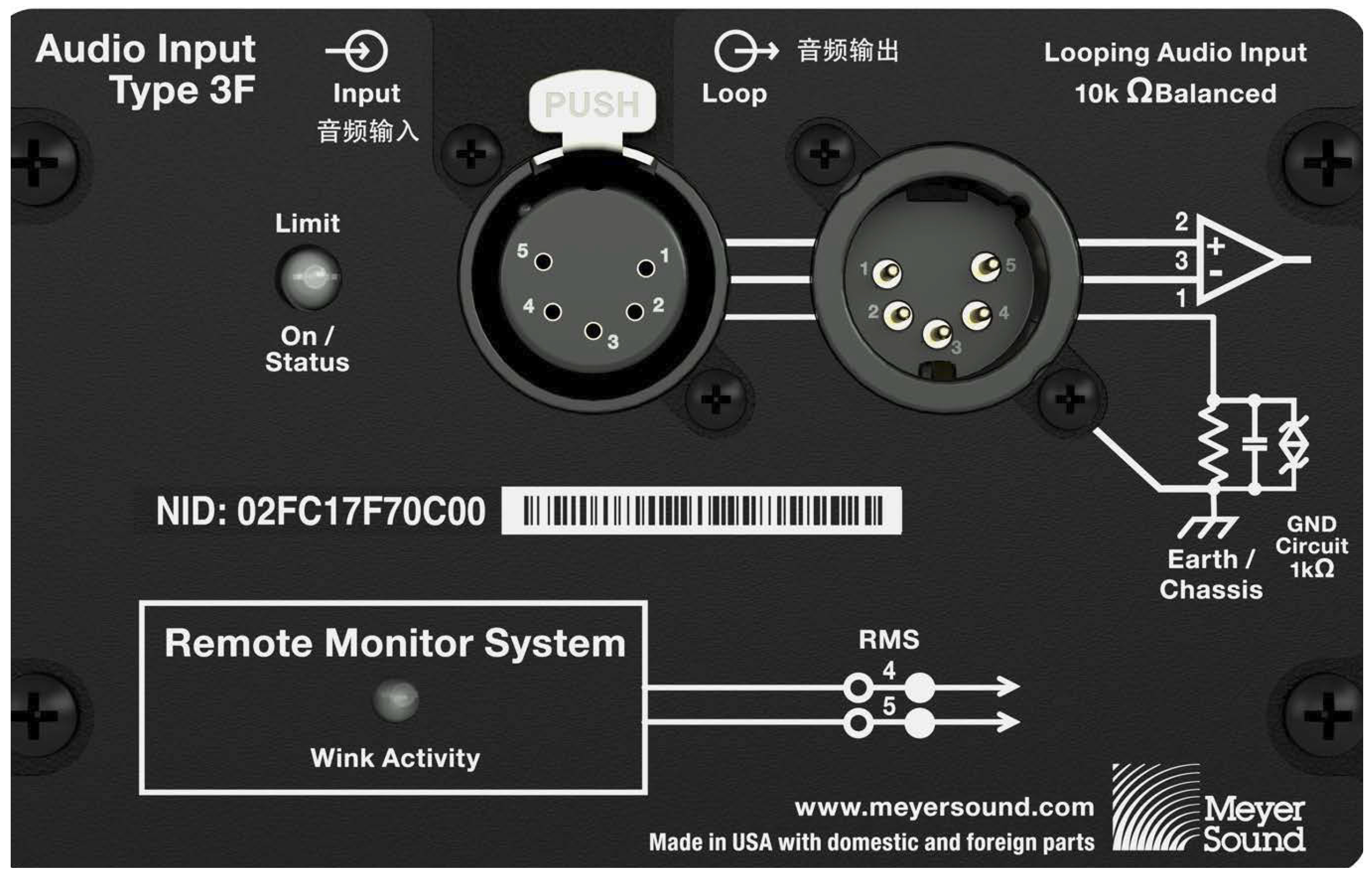
ULTRA-X20/22/23 User Panel (5-pin XLR and optional RMS)
Audio Connectors
ULTRA-X20/22/23 is available with XLR 5-pin, as shown in the first figure below, or 3-pin connectors shown in the second figure below, for audio Input and audio Loop output. XLR 5-pin connectors accommodate both balanced audio and RMS signals.
Note
The 5-pin XLR connector option is not available for weather-protected models.
Weather-protected models only are equipped with 3-pin XLR TOP (Total Outdoor Protection) connectors.
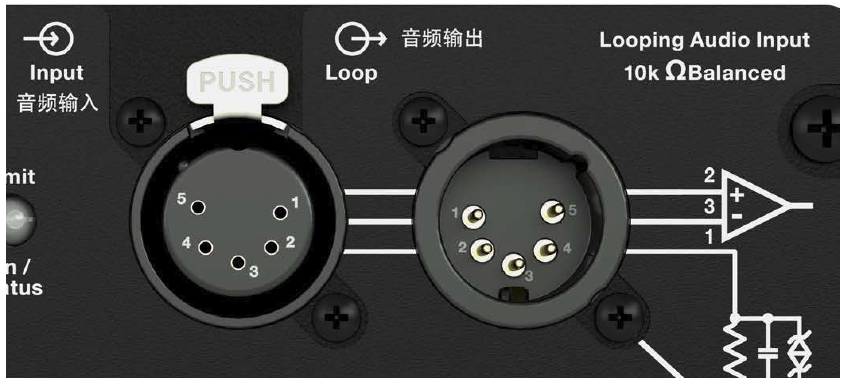
XLR 5-Pin Audio Connectors, Input and Loop Output
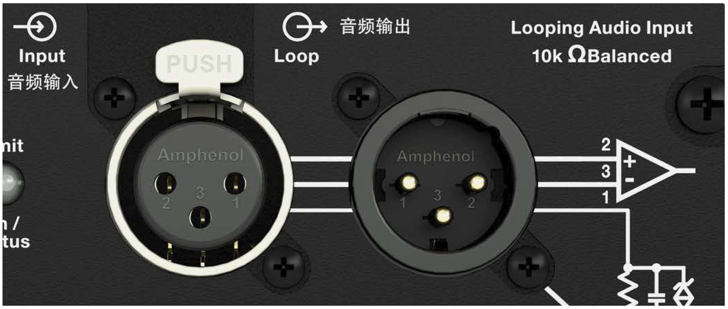
XLR 3-Pin Audio Connectors, Input and Loop Output
Audio Input (XLR 3-Pin or 5-Pin Female)
The XLR 3-pin or 5-pin female Input connector accepts balanced audio signals with an input impedance of 10 kΩ. The connector uses the following wiring scheme:
Pin 1 — 1 kΩ to chassis and earth ground (ESD clamped)
Pin 2 — Audio (+)
Pin 3 — Audio (–)
Pin 4 — RMS (polarity insensitive)
Pin 5 — RMS (polarity insensitive)
Case — Earth (AC) ground and chassis
Note
Pins 4 and 5 (RMS) are included only with XLR 5-pin connectors.
Pins 2 and 3 carry the input as a differential signal. Pin 1 is connected to earth through a 1 kΩ, 1000 pF, 15 V clamped network. This circuitry provides virtual ground lift for audio frequencies while allowing unwanted signals to bleed to ground. Make sure to use balanced XLR audio cables with pins 1–3 connected on both ends. Telescopic grounding is not recommended and shorting an input connector pin to the case may cause a ground loop, resulting in hum.
Tip
If the loudspeaker produces unwanted noise or hiss, disconnect its input cable. If the noise stops, there is most likely nothing wrong with the loudspeaker. To locate the source of the noise, check the source audio, AC power, and electrical ground.
Audio Loop Output (XLR 3-Pin or 5-Pin Male)
The XLR 3-pin or 5-pin male Loop output connector allows multiple loudspeakers to be looped from a single audio source. The Loop output connector uses the same wiring scheme as the Input connector (see Audio Input (XLR 3-Pin or 5-Pin Female). For applications that require multiple ULTRA-X20/22/23, connect the Loop output of the first loudspeaker to the Input of the second loudspeaker, and so forth.
Note
The Loop output connector is wired in parallel to the Input connector and transmits the unbuffered source signal even when the loudspeaker is powered off.
Calculating Load Impedance for Looped Audio Signals
To avoid distortion when looping multiple loudspeakers, make sure the source device can drive the total load impedance of the looped loudspeakers. In addition, the source device must be capable of delivering approximately 20 dBV (10 V rms into 600 Ω) to yield the maximum SPL over the operating bandwidth of the loudspeakers.
To calculate the load impedance for the looped loudspeakers, divide 10 kΩ (the input impedance for a single loudspeaker) by the number of looped loudspeakers. For example, the load impedance for 10 ULTRA-X20/22/23 is 1000 Ω (10 kΩ/ 10). To drive this number of looped loudspeakers, the source device should have an output impedance of 100 Ω or less. This same rule applies when looping ULTRA-X20/22/23 with other Meyer Sound self-powered loudspeakers.
Note
Most source devices are capable of driving loads no less than 10 times their output impedance.
Tip
Audio outputs from Meyer Sound’s loudspeaker GALAXY Network Platform have an output impedance of 50 ohms. Each output can drive up to 20 Meyer Sound (10 kΩ) loudspeakers without distortion.
Caution
Make sure that all cabling for looped loudspeakers is wired correctly (Pin 1 to Pin 1, Pin 2 to Pin 2, and so forth) to prevent the polarity from being reversed. If one or more loudspeakers in a system have reversed polarity, frequency response and coverage will be significantly degraded.
Weather-Protected Analog Audio Connectors
The weather-protected analog audio units are equipped with 3-pin XLR TOP connectors—a 3-pin female for the audio input and a 3-pin male for the audio loop.
Caution
Always seal connectors (input or loop) with their attached sealing caps when not in use.
This XLR TOP chassis connector is certified for outdoor protection only when used in combination with an XLR TOP cable connector or with the sealing cap in place when the chassis connector is not in use.
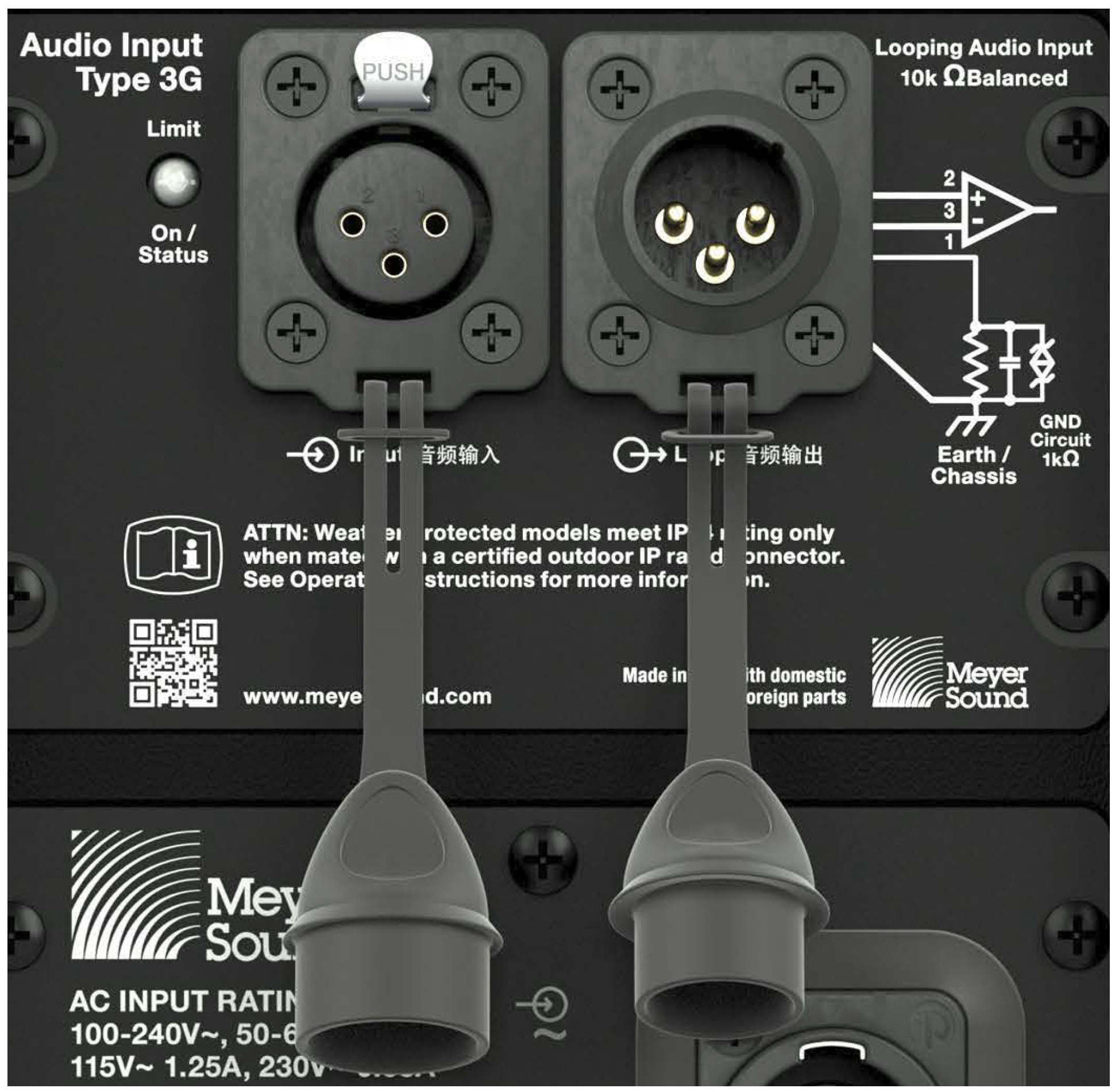
Weather-protected analog units have 3-pin XLR TOP audio connectors
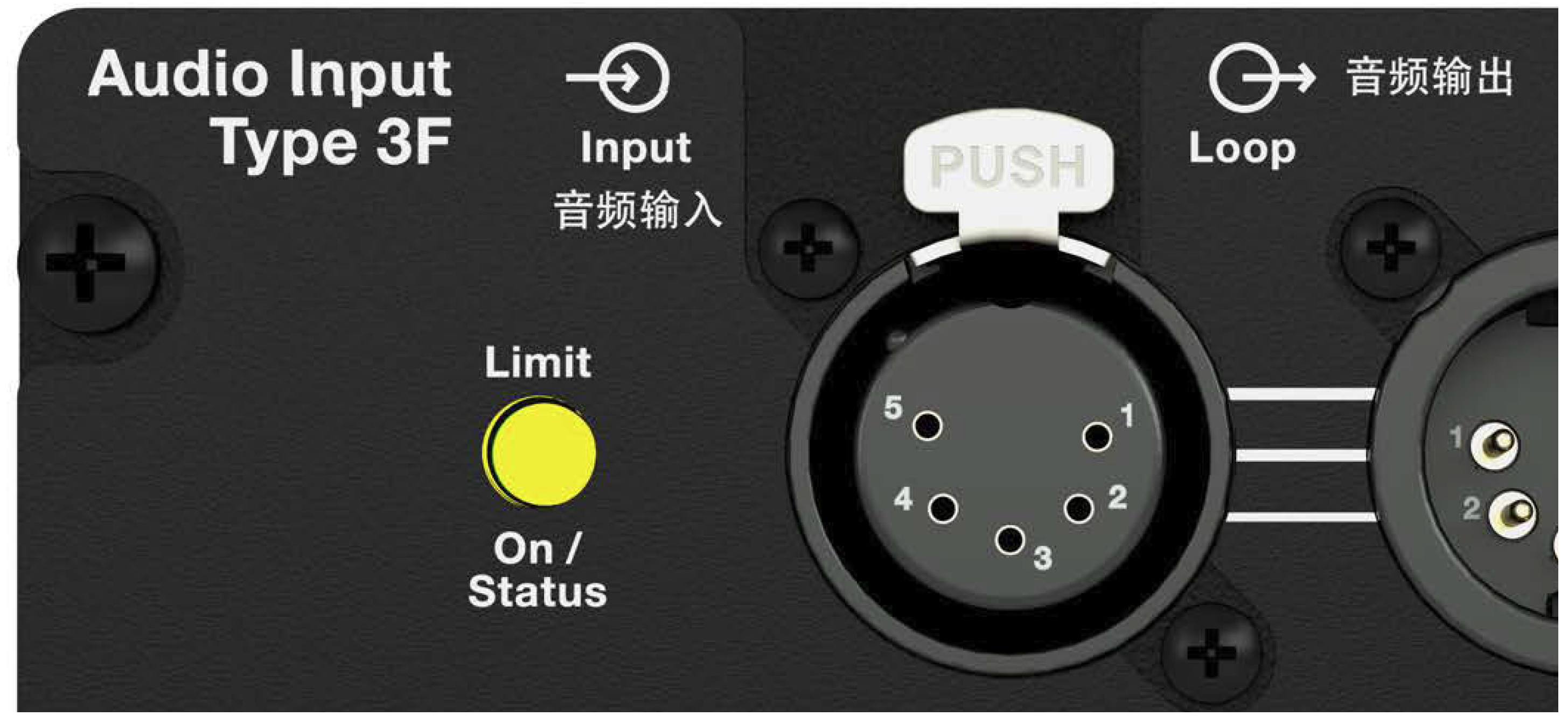
ULTRA-X20/22/23 Analog Version Limit and On/Status LED
Limiting
During normal operation, when ULTRA-X20/22/23 is powered on, the shared Limit and On/Status LED is solid green.
The low- and high-frequency drivers for ULTRA-X20/22/23 are powered by separate amplifier channels, each with their own limiter. Limiting activity is indicated by the Limit and On/Status LED illuminating yellow on the user panel. The LED, shown in the figure below, displays solid yellow for 1 second when the high-frequency channel limits and pulses yellow when the low-frequency channel limits.
ULTRA-X20/22/23 Analog Version Limit and On/Status LED
When limiting is engaged for a channel, its gain is reduced. The limiter protects the drivers and prevents signal peaks from causing excessive distortion in the amplifier, thereby preserving headroom and maintaining a smooth frequency response at high levels. When source levels return to normal below the limiter’s threshold, the LED turns green and limiting ceases.
The ULTRA-X20/22/23 performs within its acoustical specifications at normal temperatures when the Limit and On/Status LED is green, or when limiting is not continuous. During continuous limiting, the loudspeaker is nearing its operational limits, resulting in the following effects:
Increases to the input level have no effect.
Distortion increases due to clipping and nonlinear driver operation.
The drivers are subjected to excessive heat and excur- sion, which compromises their life span and may eventu- ally damage them.
Caution
The Limit and On/Status LED indicates when a safe, optimum level is exceeded. If an ULTRA-X20/22/23 loudspeaker system begins to limit before reaching the desired SPL, consider adding more units to the system.
On/Status
During normal operation, when ULTRA-X20/22/23 is powered on, the Limit and On/Status LED is solid green.
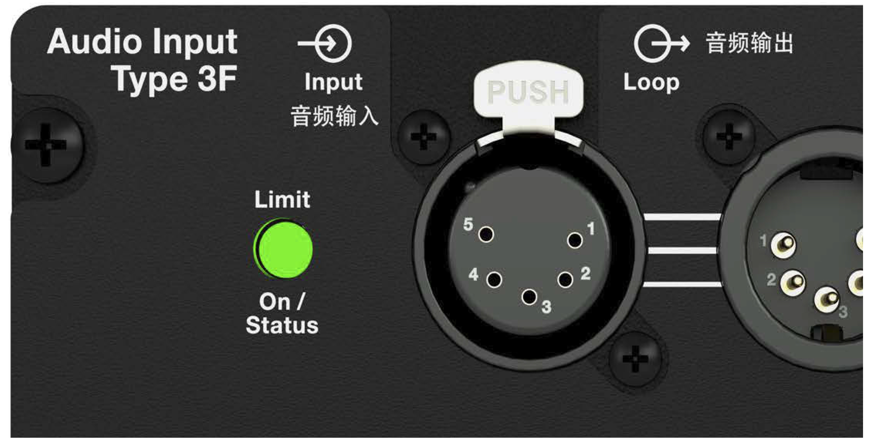
ULTRA-X20/22/23 Limit and On/Status LED
If the loudspeaker encounters a hardware fault, or the unit begins to overheat, the LED flashes red. In some instances, the loudspeaker will continue to output audio while the LED flashes red, though with a reduction in the limiter threshold and acoustic output to protect the loudspeaker.
If a loudspeaker is overheating (for RMS-equipped loudspeakers, this situation may be verified in Compass RMS), a reduction in SPL may be necessary. If after a reduction in SPL and an appropriate cooling period the Limit and On/Status LED continues to flash red (does not return to solid green), contact Meyer Sound Technical Support.
If the Limit and On/Status LED flashes red and the loudspeaker does not output audio, contact Meyer Sound Technical Support immediately.
Caution
If an ULTRA-X20/22/23 loudspeaker system consistently overheats before reaching the desired SPL, consider adding more units to the system.
Note
During startup, the Limit and On/Status LED flashes multiple colors successively.
Tip
When an ULTRA-X20/22/23 is connected to an RMS network, the Compass RMS software provides additional feedback about the loudspeaker’s hardware status and operating temperature (see RMS Remote Monitoring System).
ULTRA-X20/22/23 Digital User Panel
The ULTRA-X20/22/23 Digital user panel (also referred to as the Type 3M Audio Input Module, shown in the figure below, includes an etherCON TOP (Total Outdoor Protection) for audio input, an Ethernet connectivity LED, an On/Status LED, and a Wink button/LED.
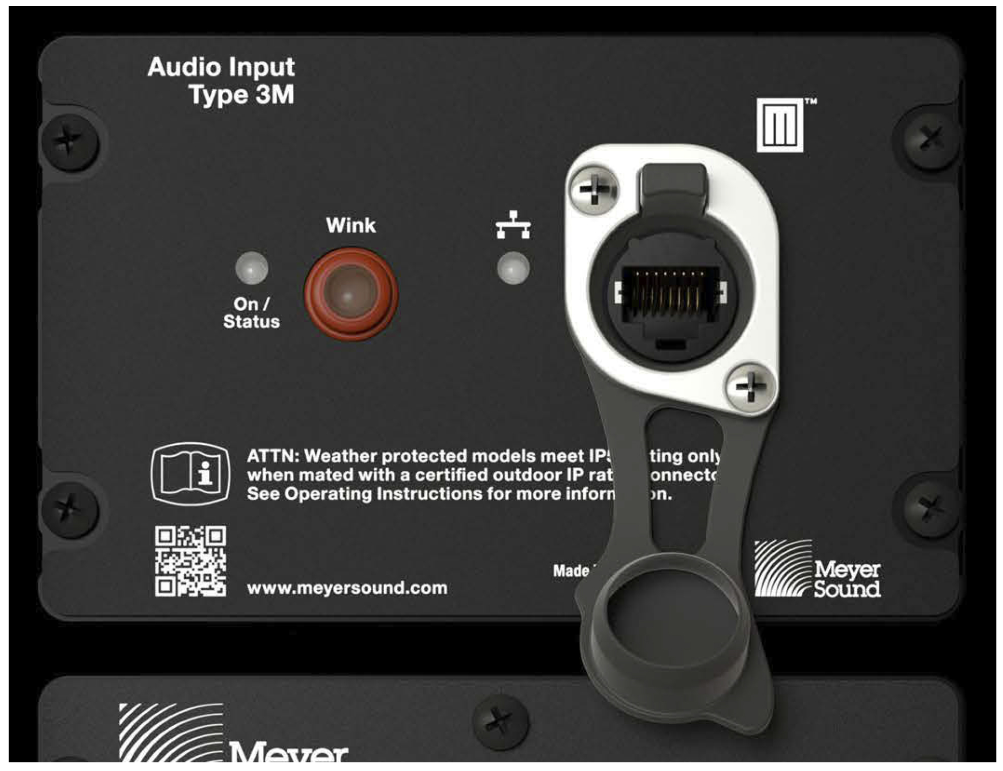
ULTRA-X20/22/23 User Panel (with etherCON TOP)
Audio Connector
ULTRA-X20/22/23 Digital has an etherCON TOP chassis connector.
Caution
Always seal the connector with the sealing cap when the connector is not in use.
This etherCON chassis connector is certified for outdoor protection only when used in combination with an etherCON TOP cable connector or with the sealing cap in place when the chassis connector is not in use.
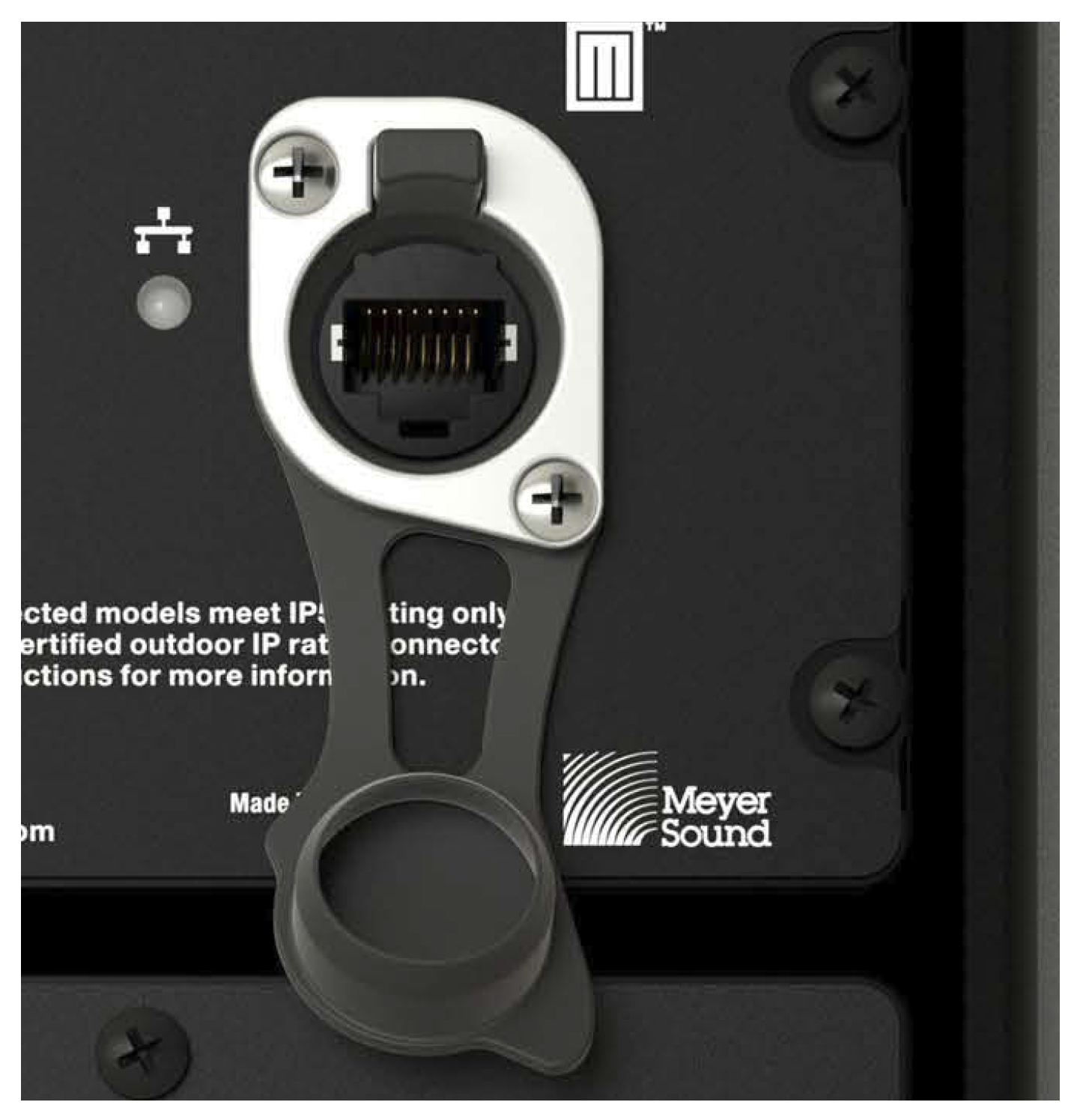
etherCON TOP Audio Input
Remote Monitoring
ULTRA-X20/22/23 Digital loudspeakers include Meyer Sound remote monitoring functionality. No additional connections are required. When an ULTRA-X20/22/23 Digital loudspeaker and Compass computer are connected to the same network via an AVB-enabled network switch, the loudspeaker will appear under the Compass Control Software Inventory tab. The ULTRA-X20/22/23 Digital loudspeaker must be allocated to an available audio source channel (Talker) as a Listener.
Wink Function
Once the ULTRA-X20/22/23Digital has been configured into a network in Compass Control Software, the icons within the loudspeaker’s detail page include a W (Wink) icon. Pressing this icon will turn it green and cause the Wink push button of the associated loudspeaker to illuminate at the center
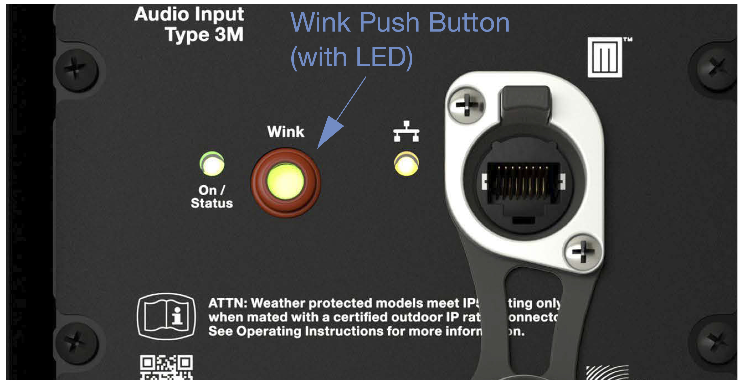
ULTRA-X20/22/23 Digital Audio Wink Push Button and LED
Conversely, if the Wink button on the ULTRA-X20/22/23Digital loudspeaker is pressed, a winking happy face is displayed on the associated loudspeaker page in Compass, as shown in the figure below.
Note
When pressed and released, the physical Wink button LED toggles between dark and solid green. When the Wink button is pressed and held, the On/Status LED will turn solid red. This is normal.
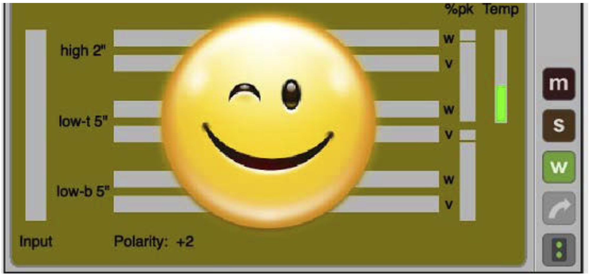
Result of Pressing Wink Button on Rear of Loudspeaker
These features facilitate matching of the physical loudspeaker to the Compass control software loudspeaker listings.
Ethernet/Network Connectivity LED
The Ethernet connectivity LED (Figure18, right) turns solid yellow when a 100Mb link is established; otherwise, it is off.
On/Status
During normal operation, when the ULTRA-X20/22/23 Digital is powered on, the On/Status LED is solid green.
The On/Status LED works in an identical manner to the analog version. It indicates limiting activity by turning yellow (see Limiting) and fault status with red (see On/ Status).
ULTRA-X20/22/23 On/Status LED and Ethernet LED (right)
Tip
When an ULTRA-X20/22/23 Digital and a computer running the Compass Control Software are connected to the same network, the Compass software provides additional feedback about the loudspeaker’s hardware status and operating temperature (see RMS Remote Monitoring System).
CONNECTING TO THE ULTRA-X20/22/23 DIGITAL VERSION
A detailed Set Up Guide for the Type 3M Audio Input Module is available at meyersound.com/documents.
Help videos are also available at meyersound.com/videos.
AMPLIFIER COOLING SYSTEM
The ULTRA-X20/22/23 loudspeaker is convection cooled. The amplifier’s heat sink provides natural convection cooling from the air flowing near its fins.
Caution
To keep ULTRA-X20/22/23 from overheating, allow at least 3 inches behind the loudspeaker for proper ventilation.
The ULTRA-X20/22/23 heat sink can reach temperatures up to 80° C (176° F) during extreme operation. Wait 15 minutes for the unit to cool before touching.
ADDING LOW FREQUENCY CONTROL
An ULTRA-X20/22/23 loudspeaker system can be deployed with Meyer Sound self-powered low frequency control elements (see [→ _bookmark43]Table 4). These subwoofers achieve very low frequency responses and extend the system response appreciably, increasing the overall acoustic power of the system in the lowest frequencies.
The ideal ratio of ULTRA-X20/22/23 loudspeakers to low frequency control element depends on the following variables:
Subwoofer model
System configuration
Frequency content of source material
Headroom required for low frequencies
For most applications, the ratios in [→ _bookmark43]Table 4 should yield good results.
Subwoofer | Frequency Response | Recommended Ratio (Number of ULTRA-X20/22/23s per Subwoofer) |
|---|---|---|
USW-112P | 36–125 Hz ±4 dB | 1:1 for most applications |
USW-210P | 32–123 Hz ±4 dB | 1:1 for most applications 1:2 for applications requiring more low end |
750-LFC | 37–110 Hz ±4 dB | 1:1 for most applications |
900-LFC | 32–115 Hz ±4 dB | 2:1 for most applications 1:1 for applications requiring extreme low end |
ADDING SUBWOOFERS BY DAISY-CHAINING
Full-range signals can be connected directly to Meyer Sound self-powered loudspeakers because the loudspeakers have built-in active crossovers. Subwoofers can be added to an ULTRA-X20/22/23 system by simply daisy-chaining them to the ULTRA-X20/22/23 loudspeakers.
To daisy-chain the suggested number of ULTRA-X20/22/23 loudspeakers for your subwoofer (see Table 1).
Connect the source signal to the Input of the first ULTRA-X20/22/23, then connect the Loop output of the first ULTRA-X20/22/23 to the Input of the second ULTRA-X20/22/23 (and so forth).
Connect the Loop output of the last ULTRA-X20/22/23 in the chain to the subwoofer Input.
When ULTRA-X20/22/23 loudspeakers are coplanar, or they are very close together, about four to six feet like in the case of pole mounting, the phase response will work well in the area of interaction and the result will be a fairly flat frequency response. However, the response will show an increase in the 60–200 Hz range where the response of the loudspeakers overlaps.
Note
If the subwoofer’s Limit LEDs begin to light before reaching the required SPL, consider adding more subwoofers to meet the SPL requirements without exposing the drivers to excessive heat and excursion.
USING A PROCESSOR
In larger systems when individual control for the ULTRA-X20/22/23 and subwoofers are needed or desired, if the ULTRA-X20/22/23 loudspeakers and subwoofer are more than six feet apart, or if a delay is required between them, use a measurement system to determine appropriate delay and polarity settings.
Caution
Make sure the source signal is sufficient to drive the total load impedance of the daisy-chained loudspeakers (see Audio Loop Output (XLR 3-Pin or 5-Pin Male)).
Tip
MAPP can be used to accurately predict the appropriate loudspeaker deployment and subwoofer integration for loudspeaker systems, complete with coverage data, system delay and equalization settings, rigging information, and detailed design illustrations. For more information, see MAPP System Design Tool.
The ULTRA-X20, ULTRA-X22 AND ULTRA-X23 loudspeakers are compatible with Meyer Sound’s QuickFly system, a comprehensive collection of custom-designed rigging, flying, and mounting options. Comprised of rugged, reliable, and easy-to-configure components, QuickFly enables deployment of ULTRA-X20/22/23 loudspeakers as either individual loudspeakers or as two-speaker clusters at precise angles to take full advantage of their directional components.
Connecting to the ULTRA-X20/22/23 Digital Version
A detailed setup guide for the Type 3M Audio Input Module is available at meyersound.com/documents.
Help videos are also available at meyersound.com/videos.
Amplifier Cooling System
The ULTRA-X20/22/23 loudspeaker is convection cooled. The amplifier’s heat sink provides natural convection cooling from the air flowing near its fins.
Caution
To keep ULTRA-X20/22/23 from overheating, allow at least 3 inches behind the loudspeaker for proper ventilation.
The ULTRA-X20/22/23 heat sink can reach temperatures up to 80° C (176° F) during extreme operation. Wait 15 minutes for the unit to cool before touching it.