Low-Mid Beam Control
Low-Mid Beam Control is a tool for GALAXY processor users to modify the natural vertical coverage of the low to mid frequencies of a Meyer Sound line array (up to 32 elements) to more closely match the high-frequency coverage (see Low-Mid Beam Control (LMBC)).
Low-Mid Beam Control (LMBC)
Low-Mid Beam Control (LMBC) is a tool that utilizes signal processing to help line arrays achieve more consistent frequency response over their vertical coverage. LMBC allows the low-mid frequency coverage of an array to be shaped (increase the vertical width) or steered (modify the direction) so that it more closely matches the array's high-frequency coverage.
Based on user-entered parameters, LMBC generates specific, unique All Pass filters for elements in a line array. These All Pass filters adjust the relative timing of low-mid frequencies compared to high frequencies, essentially allowing low-mid frequencies to be modified without affecting the coverage of high frequencies that are controlled by the horn. The result is more consistent coverage across the entire operating range of the array.
For an in-depth explanation of the theory behind LMBC, see the video on the Meyer Sound website: meyersound.com/videos/#support
LMBC should always be modeled in MAPP so that performance can be evaluated before it is implemented. To use LMBC, under the Processors tab:
Select the GALAXY processor that is controlling the line array to be modified.
Select the Settings > Low-Mid Beam Control tab, shown in the figure below.
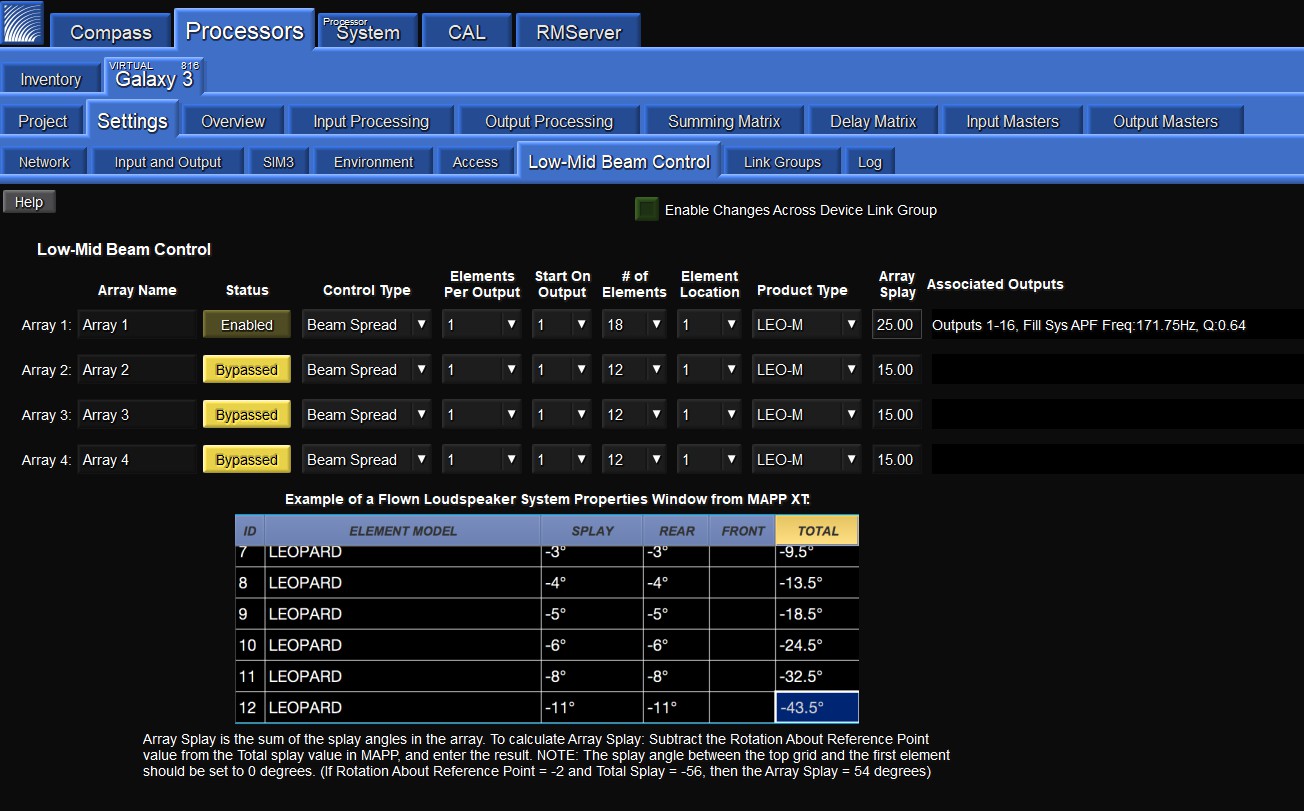
Low-Mid Beam Control tab
Under the Low-Mid Beam Control tab, there are a number of settings the user can control:
Array Name widget
Each line array being driven by this processor can be named for quick identification by clicking in the Array Name widget and entering the appropriate text.
Status button
The Status button enables or bypasses LMBC processing for all affected channels.
Control Type
Under Control Type, the user can select one of two coverage patterns: Beam Spread, or Steer Up. Beam Spread will widen the low-mid frequency coverage. Steer Up will steer low-mid frequency upward. The appropriate Control Type should be determined in MAPP prediction software.
Elements Per Output
The Elements Per Output control lets the user select whether a single processor output will drive one or two line array elements. Use one element per output for best performance.
Start On Output
Start On Output specifies which output channel will be used as the first output channel of LMBC. Element number one (1) always starts at the top of the array.
Number of Elements widget
The Number of Elements widget defines the number of elements within the array.
Element Location widget
The Element Location widget determines the element's relative position in the array. Use of this tool is necessary when LMBC processing is spread across multiple processors. For example, consider a 24-element array where each element receives a discrete LMBC filter. Two GALAXY processors are required (GALAXY A and GALAXY B). If elements 1-16 are driven by output channels 1-16 on GALAXY A, the element location for GALAXY B would be 17. Both processors 'start on output' value would be set to output 1.
Product Type widget
The Product Type widget specifies the line array product.
Array Splay widget
The Array Splay widget allows the user to enter the summed total of the splay angles within the array. To calculate array splay using the MAPP System Design Tool:
Determine the correct value from MAPP’s Array Splay located in the Loudspeaker System Properties dialog box.
Enter the result from the Compass or Compass Go Array Splay column.
Note
The splay angle between the top grid and the first element should be set to 0 degrees.
Associated Outputs
Associated Outputs display the processor outputs associated with an array’s LMBC processing. It also provides All Pass filter parameters (center frequency and Q) that can be applied to fill loudspeakers connected to other processor outputs to optimize alignment with the line array system using LMBC. In the example figure below, LMBC has been enabled for an array of LEO-M loudspeakers (Array 1).
LMBC enabled for beam spread of a LEO-M line array
Once LMBC has been enabled, the All Pass filters can be seen on each Output Processing Channel, and via the (output) Processing thumbnails on the left side of the Overview tab.
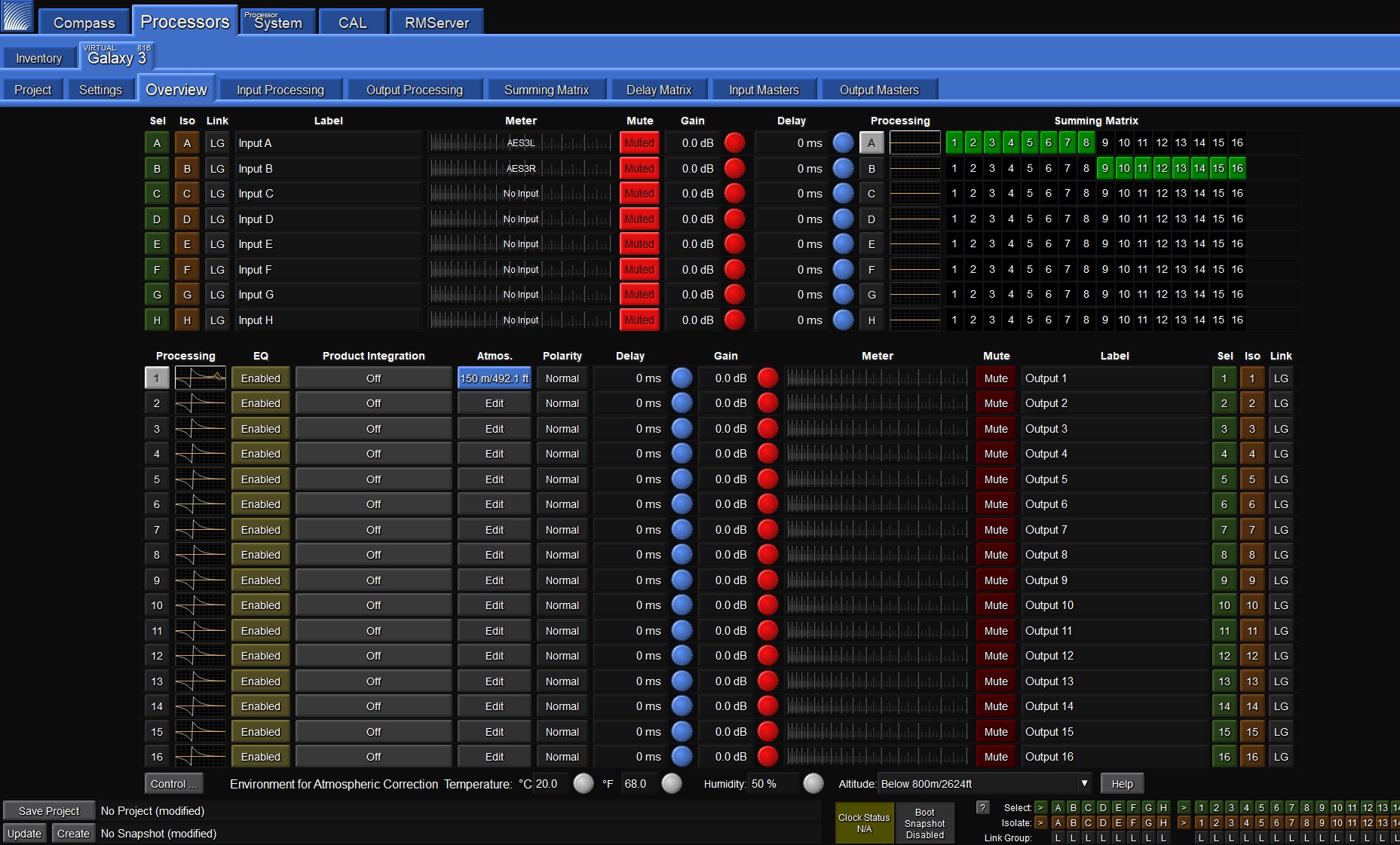
The Processing column on the Overview tab Indicates the LMBC All Pass filters
Tips for using LMBC
Signal drive lines must have correct polarity.
Apply LMBC before any other EQ is applied.
Gain tapering can make LMBC ineffective.
Do not treat array zones with different processing/gain below 1000 Hz. (e.g., correct for low-mid buildup with the same filters on the entire array, correct for HF distance only above 1 k on individual zones).
Spread is not optimal above 95° total array splay.
Steer up is not optimal above 45° total array splay.
One array element per output is optimal.
Two array elements per output is maximum and can only be used with arrays of twelve elements or more. Grating lobes will occur using this setting.
Compass control software disallows invalid or non-optimal configurations.
LMBC is not designed for mixed product types in one array.
All speakers within a system should be set to the same delay integration phase curve (PC) setting.