Assembling Arrays
Danger
BEFORE ASSEMBLING AN ARRAY, REVIEW THE Safety Statement for Rigging.
User-Provided Equipment
Depending on the application and the needs, the following equipment may be needed or considered:
Hoists, Motorized
Hoists, Manual – used for Pull-Up Configuration
Rated Rigging Hardware, e. g., shackles, wire rope, pear rings, etc.
Inclinometer
Tape Measure
Laser Distance Measurement Device
Load Cells – used to measure rigging loads
Note
When using inverted chain motors (motor down), a short length of wire rope or deck chain added between the MG-PANTHER Grid Kit and the hook on the motor allows proper collection of the take-up chain in the chain bag. These extensions also prevent the chain bag of the front motor from hanging in front of the top cabinet, obstructing the high-frequency output.
Chain Motors with Wire Rope Elevating Motors Above MG-PANTHER Grid Kit.
Additional Requirements for MG-PANTHER Grid Kit Load Ratings
Caution
If a bridle is used between MG-PANTHER Shackle bar points, the angle at the apex of the bridle legs must not be greater than 90 degrees.
The weight of any additional items suspended with the array, e. g., downfill loudspeakers, pull-back accessories, transition accessories, and cable, must be considered when calculating the weight being suspended.
Rigging Hardware Minimum Rating
Caution
When an array is suspended using two hoists, it is very likely during the assembly of an array that the entire weight of the array will be supported by only one hoist. Always use rigging hardware rated for the maximum load it may support, e. g., hoists, wire rope, shackles, etc.
Array Assembly Preparation
Use acoustic predictions provided by Meyer Sound’s MAPP System Design and Prediction software to determine the optimum array position, number of PANTHER loudspeakers required, which PANTHER models provide the coverage desired, the MG-PANTHER Shackle Bar orientation, the Grid Kit height and angle, and the splay angles between cabinets.
From the MAPP design, document the following array information:
Trim height
Grid rotation angle
MG-PANTHER Shackle Bar orientation (forward/max downtilt or rearward/max uptilt)
If suspending from a single-point, document which attachment point of the MG-PANTHER Shackle Bar to connect the hoist to
Splay angles of PANTHER cabinets
Locations in the array of PANTHER models
Front and rear rigging weights
Total array weight
Drive lines, Galileo GALAXY output channels
Note
In some regions, regulations require dead hanging of all suspended loads, bypassing the loading of all moveable hoists. A dead hang uses a wire rope or chain to carry the suspended load, removing the entire load from the hoisting mechanism(s) used to raise and lower the array. Ensure the proper rigging equipment is available when needed.
Structural Attachment Point Locations
Install and locate the rigging points above the intended location of the array. The spacing of the rigging points described below is based on the dimensions of the hardware. There are several possible configurations:
MG-PANTHER Grid Kit Only
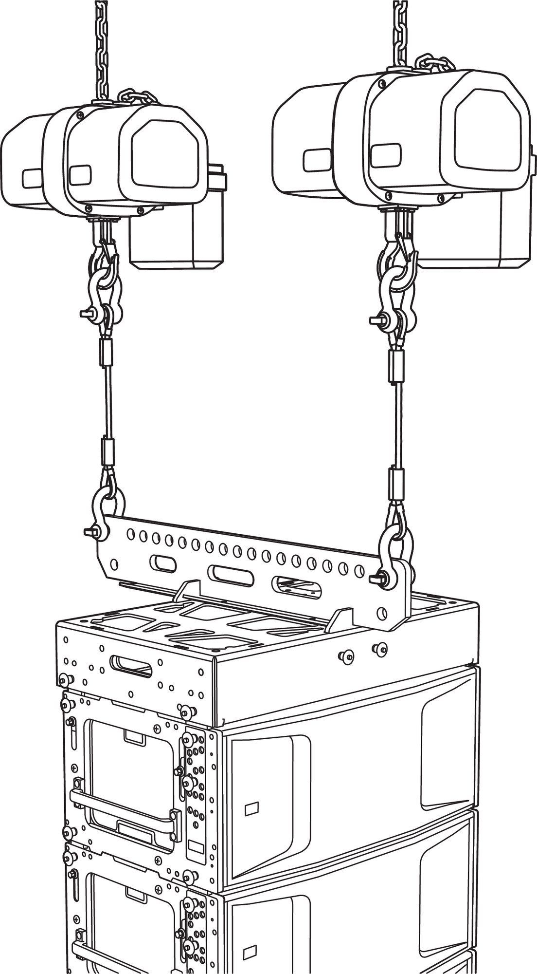
Dual-Point Suspension: Hoists, MG-PANTHER Grid Kit, PANTHER Cabinets
Two-Points: Locate the MG-PANTHER attachment points defined in the MAPP design (array Reference Point Position) in the venue. From the array Reference Point in MAPP, locate the second point 40 in (1 m) away from the first point.
MG-PANTHER Grid Kit Hoist Locations
Single-Point: Refer to the MAPP design to determine the location of the structural attachment point by enabling the center of gravity marker that extends above the array.
If the center of gravity of the array does not align with a hole on the MG-PANTHER Shackle Bar and the grid angle is critical for the application, a bridle with an adjustable length leg connected to two holes of the MG-PANTHER Shackle Bar and the hoist provides fine adjustment of the grid angle.
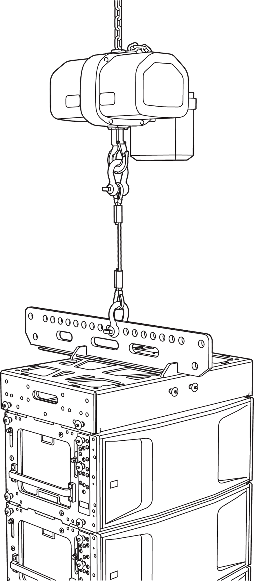
Single-Point Suspension: Hoists, MG-PANTHER Grid Kit, PANTHER Cabinets
MG-PANTHER Grid Kit and MVP Motor V Plate
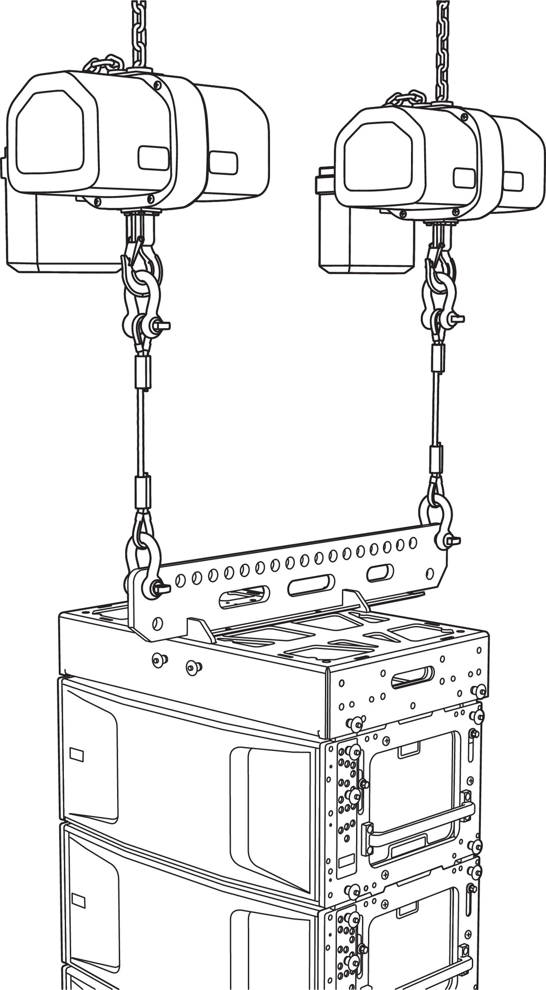
Three structural attachment points are needed. Two of the points are used for hoists connected to the top of the MVP Motor V Plate (outermost holes). The third structural attachment point connects a hoist to the MG-PANTHER Shackle Bar (point 1 or 19). The bottom of the MVP Motor V Plate connects to the opposite end of the MG-PANTHER Shackle Bar (point 1 or 19).
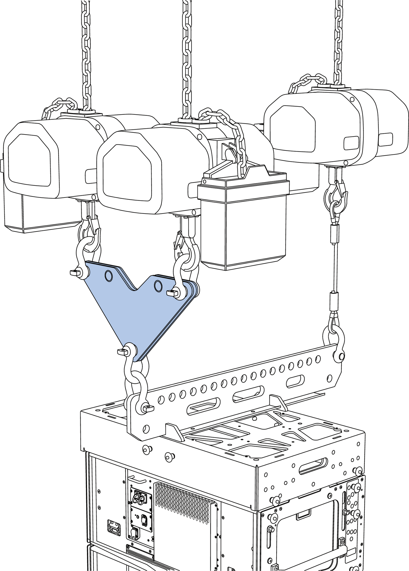
MVP Motor V Plate Configuration: Hoists, MVP-Motor V Plate, MG-PANTHER Grid Kit, PANTHER Cabinets
The rigging points for the MVP Motor V Plate can be up to 30 in (75 cm) apart to allow more space between the hoists, provided there is at least 8 ft (2.5 m) between the top of the MVP Motor V Plate and the structural attachment points. If the distance between the top of the MVP Motor V Plate and the structural attachment points is less than 8 ft (2.5m), the distance between the two rigging points is limited to 20 in (50 cm) apart.
The third point is located 40 in (1 m) from the points used for the MVP Motor V Plate.
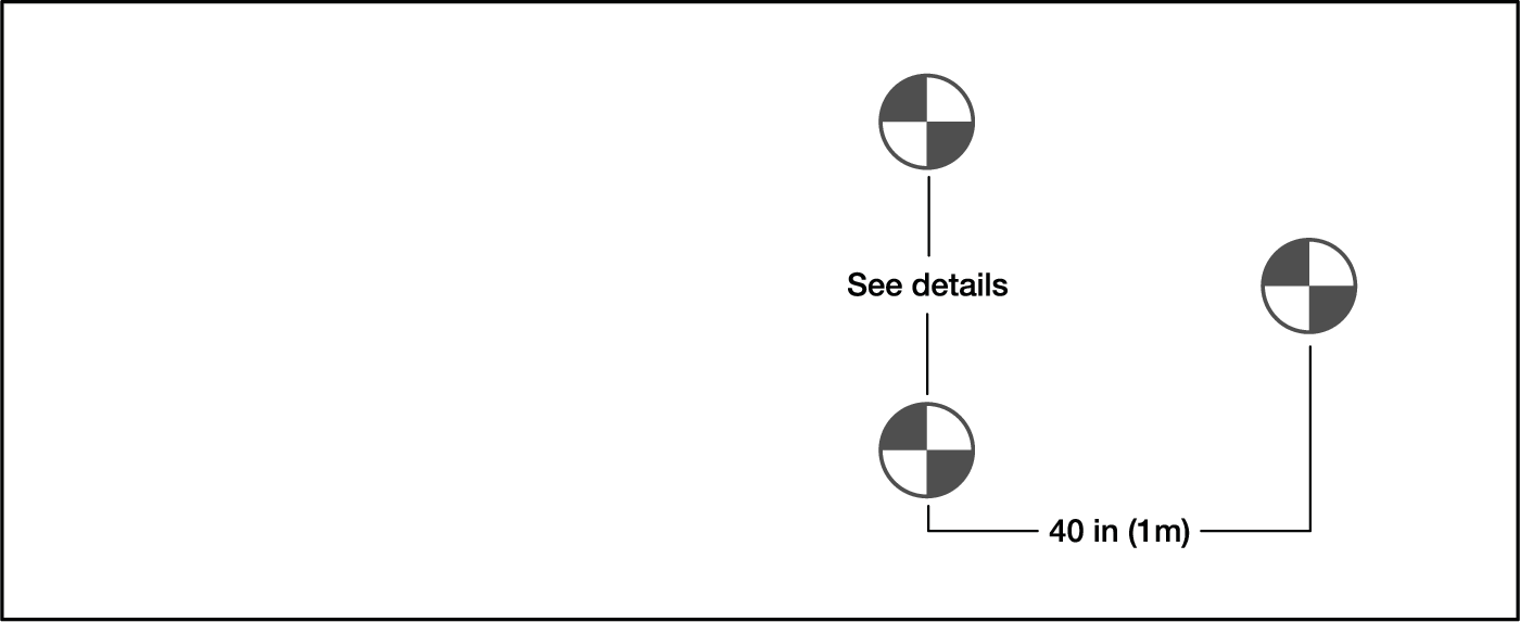
Grid Kit Hoist Locations for MG-PANTHER and MVP Motor V Plat
MG-PANTHER Grid Kit, Pull-Up Configuration
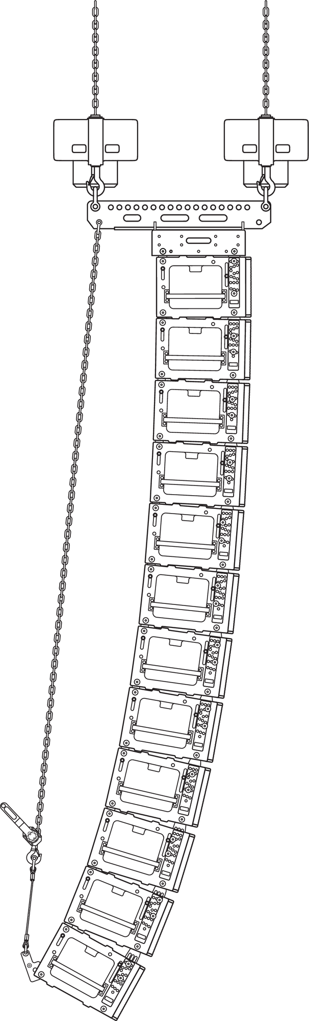
Pull-Up Configuration: Hoists, MG-PANTHER Grid Kit, PANTHER Cabinets, PBF-LYON, Manual Hoist
One or two structural attachment points are used to connect hoists to the MG-PANTHER Shackle Bar. The PBF-LYON is connected to the bottom cabinet of the array. A manual hoist connects the bridle of the PBF-LYON to the lower utility point of the MG-PANTHER Shackle Bar.
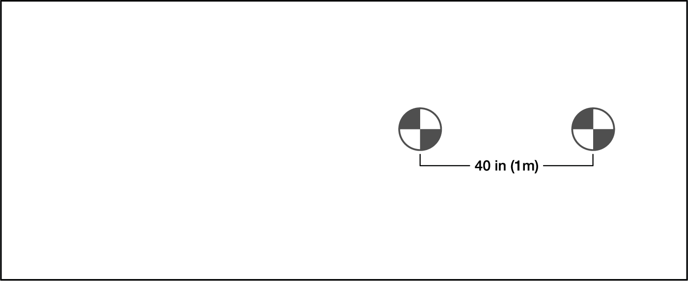
Hoist Locations, Two Hoists 40-inches Apart
Note
The MVP Motor V Plate can be used in conjunction with the pull-up configuration.
MG-PANTHER Grid Kit, Pull-Back Configuration
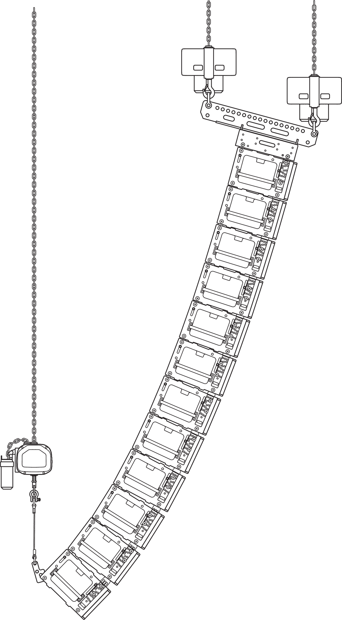
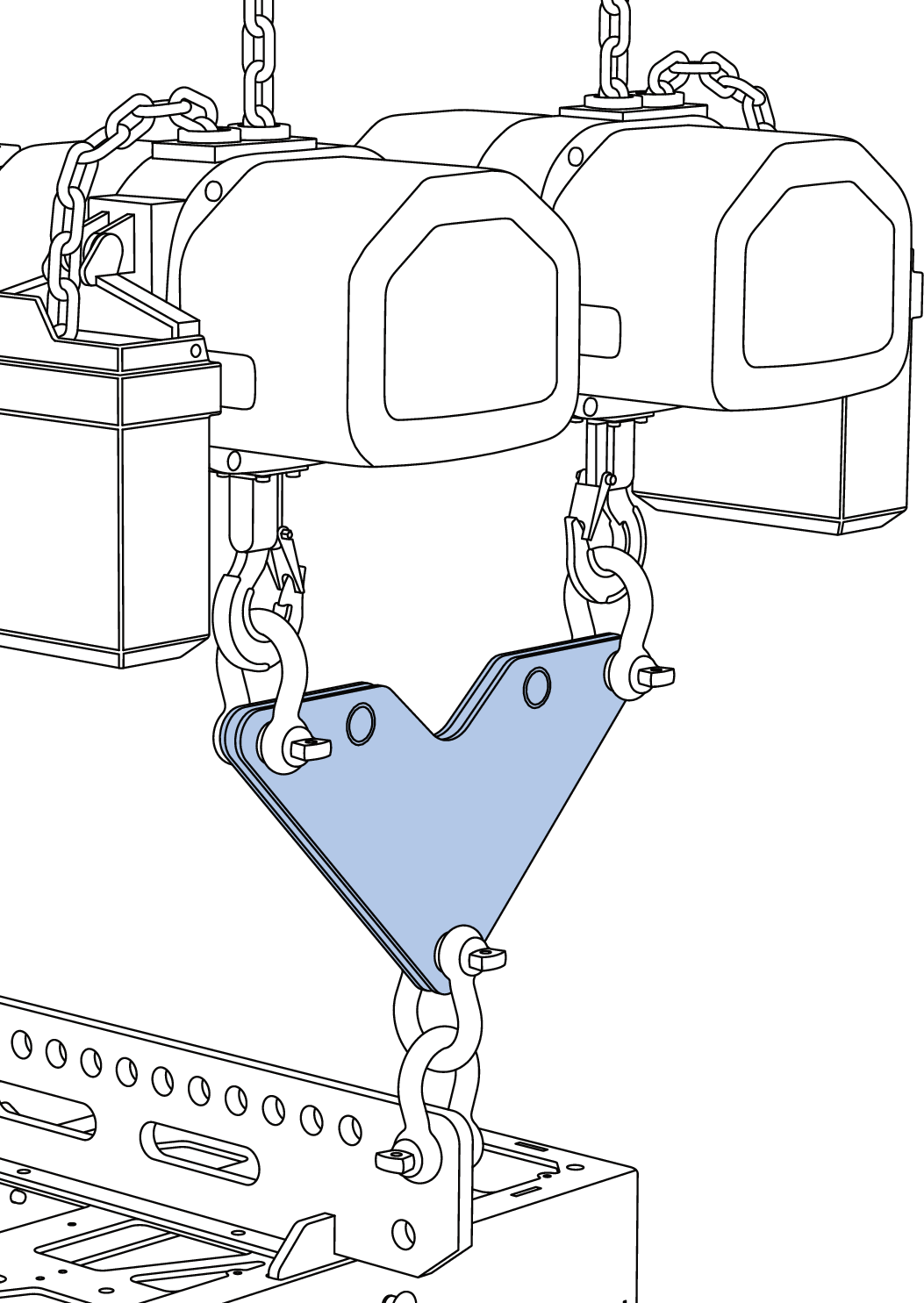
Pull-Back Configuration: Three Hoists, MG-PANTHER Grid Kit, PANTHER Cabinets, PBF-LYON
Caution
When trimmed, the maximum angle between the bottom of the array and the structural attachment point is +/- 10 degrees from vertical.
Note
The MVP Motor V Plate is not intended for use when the array is in the pull-back configuration as it provides insignificant horizontal rotation of an array in the pull-back configuration.
Three structural attachment points are used. Two points connect hoists to the MG-PANTHER Shackle Bar at points 1 and 19. The third point is located directly behind the first two points and directly above the bottom of the array when it is trimmed. This point connects a hoist to the bridle of the PBF-LYON. The distance between the MG-PANTHER Shackle Bar points and the rigging point for the hoist connected to the PBF-LYON is determined in MAPP.
Hoist Locations, Two Hoists 40-inches Apart
Array Assembly Steps
Because the PANTHER cabinets are horizontally symmetrical, when the steps below give instructions related to one side of a cabinet, always duplicate the action on the other side of the cabinet. The duplicate instruction for the other side of the cabinet is not included.
These instructions assume the PANTHER cabinets are already stacked on caster frames, ready for temporary installation, e. g., touring or one-off events, and that the MG-PANTHER Grid Box is not already connected to the top
PANTHER cabinet. For installations, it is likely that individual cabinets will be located on the working surfaces below the rigging points and added one at a time to the array. If there are questions, please contact Technical Support by visiting meyersound.com/contact.
Ready the hoisting mechanism(s).
Caution
Discover and follow all safety regulations and operational rules regarding movement of suspended loads for the region, location, and venue where the system will be deployed.
Securely mount any accessories to the MG-PANTHER Grid Kit, e. g., lasers, inclinometers, tape measure, etc.
Prepare PANTHER cabinets.
Remove protective covers from stacks of PANTHER cabinets and arrange the stacks in the order they will be added to the array.
For each PANTHER cabinet, except the top cabinet of the array:
Move a quick-release pin to the gray-on-black ANGLE hole that matches the MAPP design.
Remove the quick-release pin from the white-on- gray LOCK hole or the 0° GRID / TRANSPORT hole, allowing the pin to hang by its lanyard.
For the top cabinet of the array:
Insert a quick-release pin in the gray-on-black ANGLE hole labeled STOW / GRID 7° when connecting this cabinet to the grid.
Within the stacked cabinets, make sure all the rear GuideALinks are extended and pinned in place, connecting adjacent cabinets.
Note
The links of the top cabinet of each stack should have the GuideALinks retracted into the cabinet.
Connect the MVP Motor V Plate to hoists, if used.
Connect 3/4-inch or 7/8-inch shackles to all three MVP Motor V Plate connection points.
Connect the hoists to the two shackles at the top of the MVP Motor V Plate.
MVP Motor V Plate, Two Hoists Connected to Top Connection Points
Connect the MG-PANTHER Shackle Bar to hoist(s).
Locate the MG-PANTHER Shackle Bar on the floor or a cable trunk directly below the hoist(s).
Note
Confirm the MG-PANTHER Shackle Bar orientation (forward/rearward) matches the MAPP design orientation.
Connect 3/4-inch or 7/8-inch shackles to the MG- PANTHER Shackle Bar.
When using two hoists, connect shackles to holes 1 and 19 of the MG-PANTHER Shackle Bar.
When using a single hoist, ensure the shackle is connected to the point on the MG-PANTHER Shackle Bar defined in the MAPP design.
When the MVP Motor V Plate is added, connect the shackle at the bottom of the MVP Motor V Plate to a second 3/4-inch or 7/8-inch shackle connected to one end (hole 1 or 19) of the MG-PANTHER Shackle Bar.
Raise the hoists until the Shackle Bar is above the height of the Grid Box, whether on the floor, cable trunk, or on a stack of cabinets.
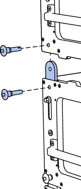
Connect the MG-PANTHER Shackle Bar to the MG-PANTHER Grid Box
Locate the Grid Box under the suspended Shackle Bar.
Lower the Shackle Bar, aligning the mounting tabs of the Shackle Bar with the slots in the Grid Box, until the Shackle Bar rests on the Grid Box.
Use the four 1/2 x 1.50-inch QRP (red button, PN 134.045) pins to secure the Shackle Bar to the Grid Box.
Caution
Make sure the quick-release pins are fully inserted and locked, unable to be removed without depressing the button of the quick- release pin.
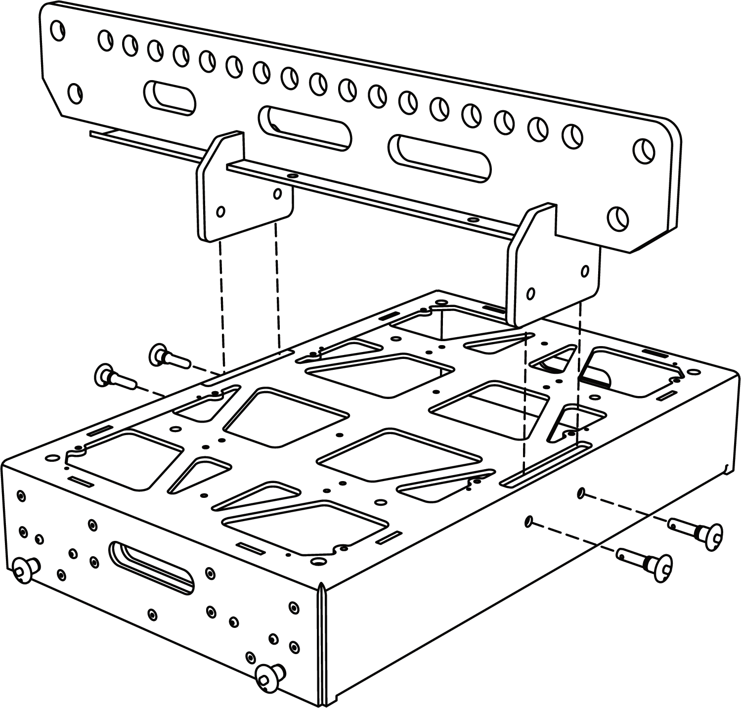
MG-PANTHER Grid Kit, MG-PANTHER Shackle Bar, Exploded View
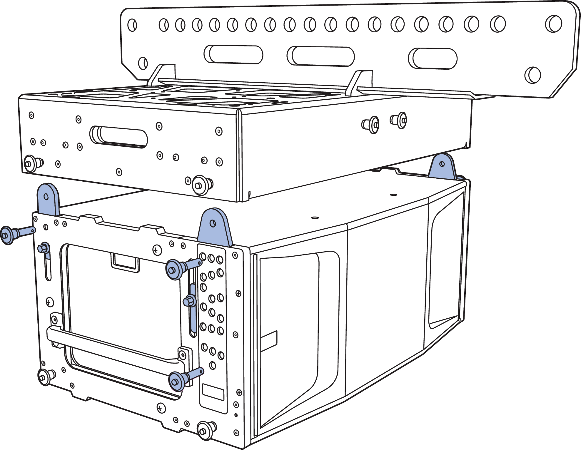
Connect the MG-PANTHER Grid Kit to the first stack of PANTHER cabinets.
Raise the MG-PANTHER Grid Kit until it is higher than the PANTHER cabinets being connected.
Move the first stack of PANTHER loudspeakers under the MG-PANTHER Grid Kit.
Lower the MG-PANTHER Grid Kit until it is 1 to 2 inches (2.5 cm to 5cm) above the top PANTHER cabinet, close enough to allow the front GuideALinks to extend into the GuideALink sockets of the MG-PANTHER Grid Box.
Caution
Do not attempt to “land” the MG-PANTHER Grid Kit on a PANTHER cabinet with the GuideALinks extended. Collision of the GuideALinks and the GuideALink sockets will cause excessive wear over time.
Note
For the top PANTHER cabinet, there should already be a pin in the gray-on-black ANGLE STOW / GRID 7° hole, see Step 3 above.
For the top PANTHER cabinet, grasp the hex knob of the front GuideALink and lift it until a quick-release pin can be inserted in the 0° GRID / TRANSPORT hole (below the white-on-black LOCK holes). The GuideALinks won’t be entirely seated but will guide the MG-PANTHER Grid Kit when it is lowered.
Lower the MG-PANTHER Grid Kit until its weight is supported by the front GuideALinks.
Secure the front GuideALink to the MG-PANTHER Grid Kit by inserting the 7/16 x 1.50-inch QRP (red button, PN 134.051) quick-release pin attached by lanyard to the MG-PANTHER Grid Box.
Remove the quick-release pin securing the rear GuideALink of the top PANTHER cabinet. Lift the rear GuideALink using the hex knob and replace the quick-release pin, securing the GuideALink in the raised position.
Secure the rear GuideALink of the PANTHER cabinet to the MG-PANTHER Grid Box by inserting the 7/16 x 1.50-inch QRP (red button, PN 134.051) quick-release pin attached by lanyard to the MG-PANTHER Grid Box.
Caution
Make sure the quick-release pins are fully inserted and locked, unable to be removed without depressing the button of the quick- release pin.
Secure MG-PANTHER Grid Kit to Top PANTHER Cabinet with GuideALinks
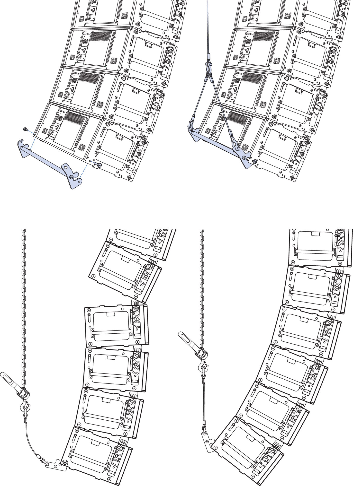
Connect the cable strain relief (cable pick) to the Utility hole at the end of the Shackle Bar.
Note
When an array is configured for pull-up with the PBF-LYON, connect a shackle with a pear ring to the utility point on the MG-PANTHER Shackle Bar. Use additional shackles connected to the pear ring to connect the cable pick and the manual hoist chain, see PBF-LYON.
Visually inspect the assembly before hoisting, make sure:
The rigging hardware is properly oriented and won’t “jam” or “foul,” especially the shackles.
Cables are properly routed and will not be strained, pinched, or damaged when the array is raised.
Each cabinet is linked to the cabinet above it, verifying that the front and rear GuideALinks are extended and pinned in place with 7/16 x 0.90-inch QRP (black button, PN 134.065) quick-release pins attached by lanyard to PANTHER cabinet.
The pins in the gray-on-black ANGLE holes match the splay angles in the MAPP design.
Remove the quick-release pins from the white-on-gray LOCK holes, leaving them hanging by their lanyards.
Remove the MCF-PANTHER Caster Frame
Using the hoists, lift the array until all the caster frame wheels no longer touch the working surface. The front GuideALinks will extend as the cabinets are hoisted.
Remove the MCF-PANTHER Caster Frame
Caution
Do not lift the caster frame by the handles while it is being attached to a cabinet. This creates a pinch point for hands. Only lift the caster frames by the handles when the caster frame is not connected to a cabinet.
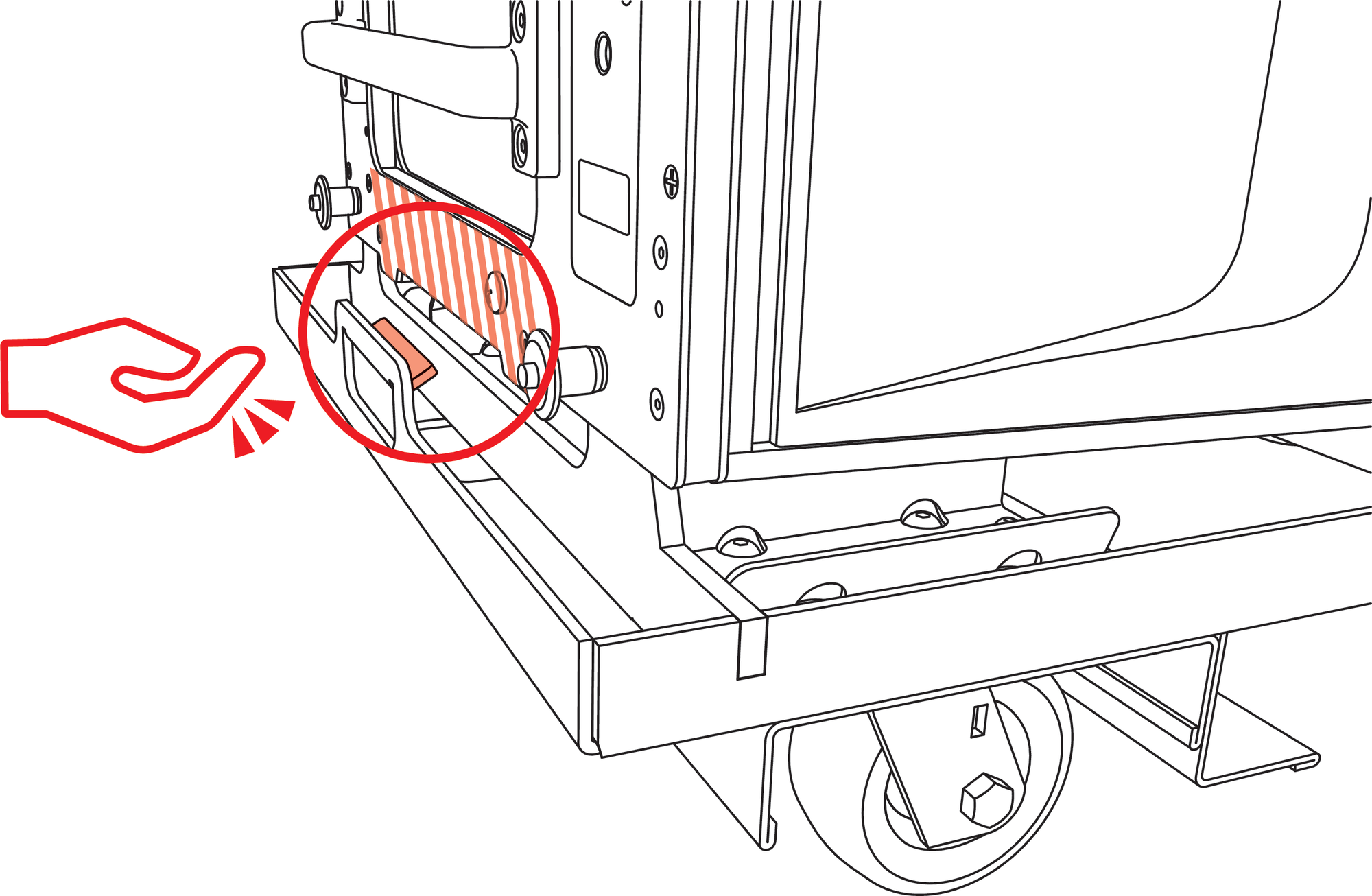
Caster Frame Handle Pinch Poin
First, remove both front pins that secure the caster frame while supporting the underside of the caster frame by hand.
Lower the front wheels to the floor.
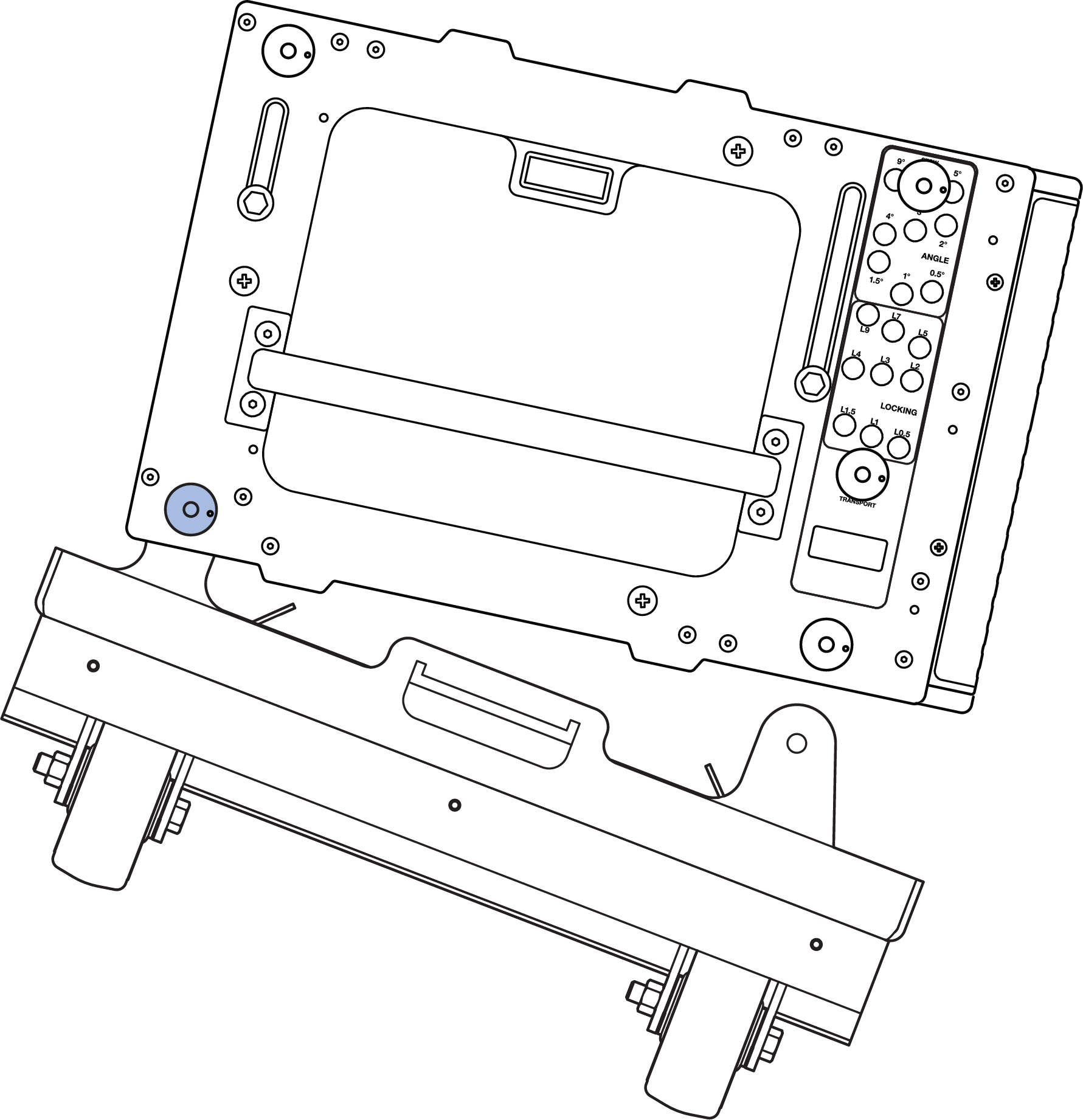
Detach Front of Caster Frame First
Next, remove both rear pins that secure the caster frame while supporting the underside of the caster frame by hand.
Lower the rear wheels of the caster frame to the floor
Replace the pins that secured the caster frame in the same holes of the PANTHER cabinet.
Caution
Always lower the front of the caster frame first. If the rear is lowered first and it is high enough off the ground, the caster frame can swing and damage the front lip of the PANTHER cabinet.
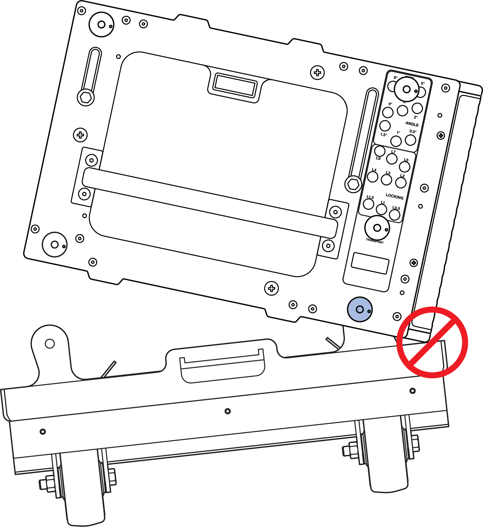
Do Not Lower the Rear of the Caster Frame First
Lock the splay angles.
For each cabinet, insert the quick-release pins hanging from lanyards in the white-on-gray LOCK holes that correspond to the gray-on-black ANGLE holes.
Caution
Make sure the quick-release pin locations for the white-on-gray LOCKING holes match those of the corresponding gray-on-black ANGLE holes, and that the locations of the quick-release pins for the left and right sides of the cabinets mirror each other.
Make sure the quick-release pins are locked and fully inserted
Tip
The LOCK hole that corresponds to an ANGLE hole is always three holes below the ANGLE hole.
Connect the power, audio signal, and network cables for each cabinet. Use the cable rings on the rear of the cabinets for strain relief.
Prepare to connect another stack of loudspeakers.
Ensure the connected cabling has enough slack to not be strained, pinched or damaged as the array is raised.
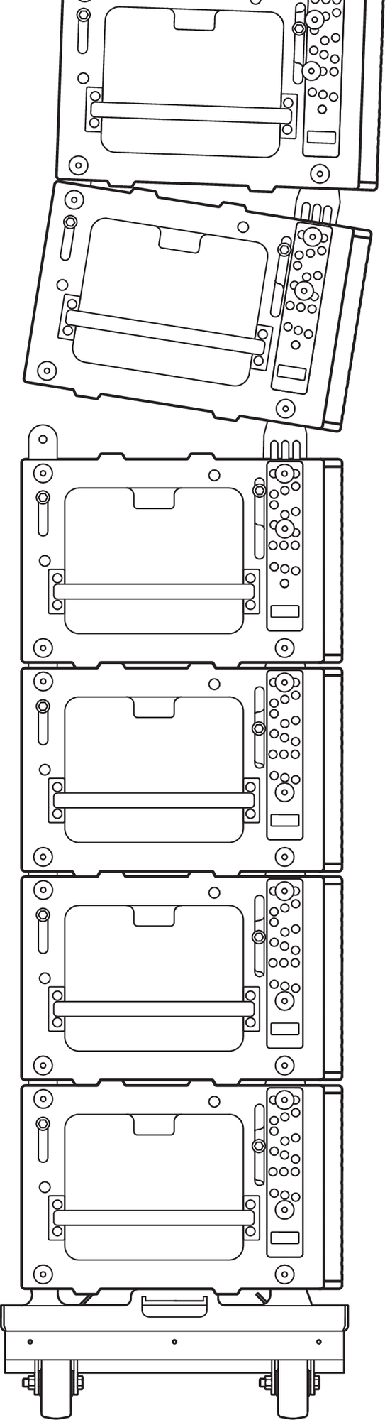
Raise the array 6 inches (15 cm) higher than the next stack of PANTHER cabinets to be attached.
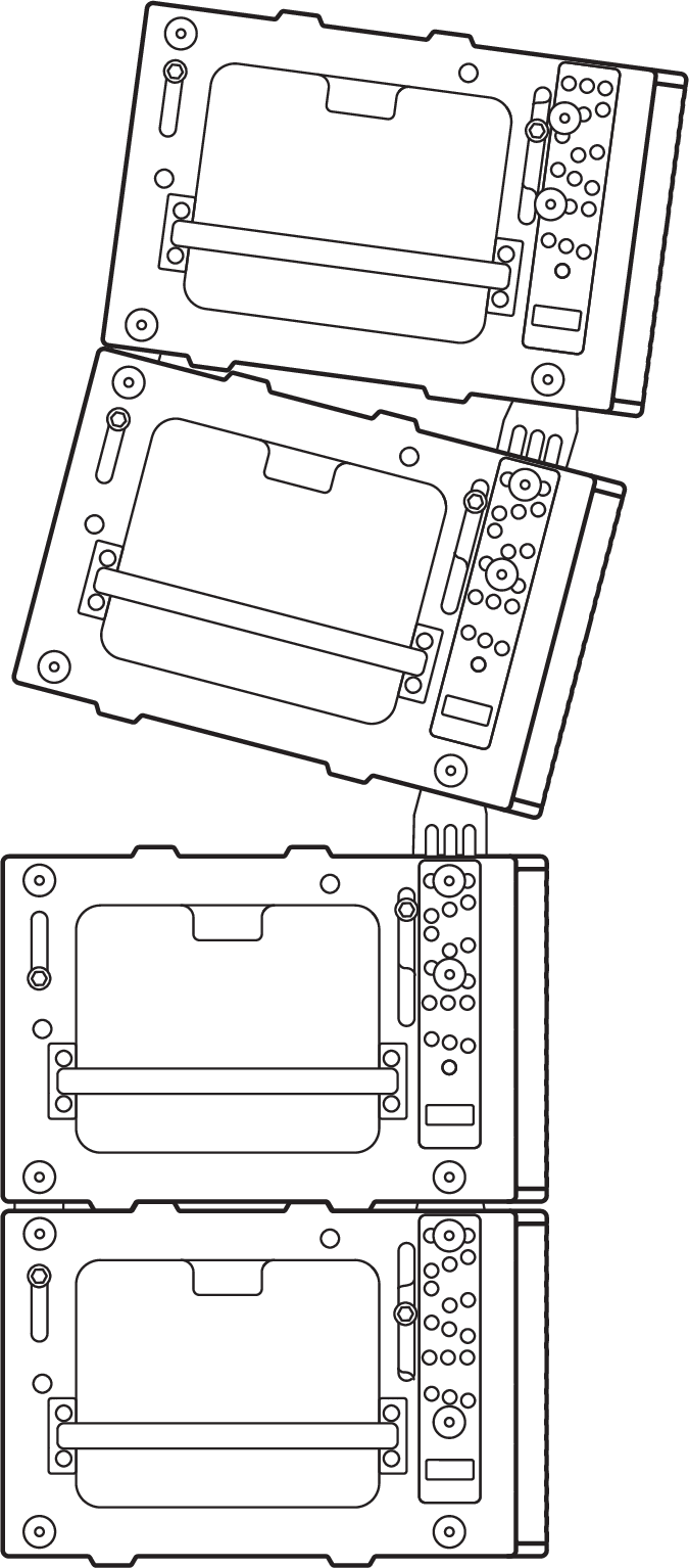
Tip the array up until the centerline of the suspended bottom cabinet is parallel to the working surface, e. g., floor, ground, stage, etc.
Suspended PANTHER Array, Tilted Up to Connect to a Stack of PANTHER
Note
If the load of the array is entirely transferred to the front hoist and the bottom of the cabinet is not parallel to the working surface, use the PBF-LYON in the Pull-Up configuration to aid in connecting the rear GuideALinks, see Pull-Up Configuration Overview.
Move the stacked cabinets under the suspended cabinets, aligning the corners.
Make sure the GuideALinks of the top stacked cabinet are retracted.
Caution
Do not attempt to “land” the suspended cabinets on a stacked cabinet with the GuideALinks extended. Collision of the GuideALinks and the GuideALink sockets will cause excessive wear over time. Collision of an extended GuideALink and the wooden bottom of a cabinet above it can puncture or damage the cabinet.
Lower the suspended cabinets within 1 to 2 inches (2.5 to 5 cm) above the top of the cabinet to be connected.
Connect the next stack of loudspeakers.
Extend the front GuideALink into the link socket of the suspended cabinet and secure it to the suspended cabinet with the 7/16 x 0.90-inch QRP (black button, PN 134.065) attached by lanyards to PANTHER cabinets. Remove the quick-release pin in the gray-on-black ANGLE holes if the front
Lower the suspended cabinets within 1 to 2 inches (2.5 to 5 cm) above the top of the cabinet to be connected.
The front GuideALinks keep the flown cabinets aligned to the stacked cabinets
If removed, replace the quick-release pin in the gray-on-black ANGLE hole of the top cabinet being connected.
Extend both rear GuideALinks into the suspended cabinet and secure them with the 7/16 x 0.90-inch QRP (black button, PN 134.065) attached by lanyards to PANTHER cabinets.
Note
The lanyards of the quick-release pins may be damaged if quick-release pins are inserted in an adjacent cabinet.
Rear GuideALink Extended, Secured with Two Quick-Release Pins
Caution
Make sure the quick-release pins are fully inserted and locked, unable to be removed without depressing the button of the quick-release pin.
During array assembly, the bottom of longer arrays can move forward and backward a significant distance when minor changes to the hoist elevations are made. Keep the area in front of and behind the array clear of personnel and equipment to avoid unintentional impact.
Repeat Steps 9-14 for each additional stack of PANTHER cabinets to be added to the array.
See the Array Assembly Notes if it is not possible to tip the suspended cabinets enough to connect the rear GuideALinks of the stacked cabinets to the suspended cabinets because the rear hoist becomes slacked, carrying no weight.
Unable to Tip Suspended Cabinets Enough to Connect Rear GuideALinks.
Connect PBF-LYON for pull-up or pull-back configurations.
Raise the array enough to remove the caster frame. Connect the PBF-LYON Pull Back Frame to the bottom cabinet.
Connect sufficiently rated hardware to the pull-back frame to form a bridle.
For a pull-up configuration, connect the bridle of the pull-back frame to a manual hoist, which is connected to the utility point on the shackle bar.
For the pull-back configuration, connect the bridle of the pull-back frame to the pull-back hoist.
Before Raising the Array
Make sure all cabinet-to-cabinet GuideALinks are secured with the 7/16 x 0.90-inch (black button) quick-release pins (PN 134.051) included with PANTHER cabinets.
Make sure the connected rigging hardware is properly aligned, especially the shackles.
Make sure the connected cabling has enough slack to not be strained and won’t be pinched or snag as the array is lifted.
If using a single hoist, verify the tilt angle of the MG-PANTHER Grid Kit matches the array design.
Note
At this point in the assembly process, users typically terminate the power, signal, and network cabling and verify proper signal patching.
Transitioning to Pull-Back Configuration
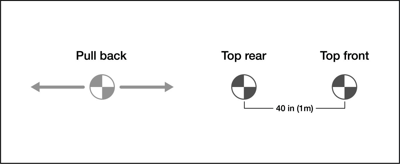
When suspending an array configured for pull-back, follow these steps to transition the load of the array from the two hoists connected to the MG-PANTHER Shackle Bar to the pull-back hoist and the rear hoist connected to the MG-PANTHER Shackle Bar , as shown in the figure below.
Caution
During the transition, tension of the rigging hardware is likely to be relieved which increases the likelihood shackles will become misaligned or “fouled”. Make sure all rigging remains properly aligned during array assembly and positioning.
With the pull back hoist not taking weight, raise all three hoists until the array is at the approximate trim height.
Raise the pull-back hoist until it begins to carry weight.
Lower the top front hoist until it no longer carries weight.
Raise the pull-back hoist until the desired grid angle is achieved.
Note
It may be necessary to lower the top front hoist if it approaches taking weight.
Raise or lower both the pull back and top rear hoists to achieve the desired trim height.
Raise the top front hoist until it just begins to take weight.
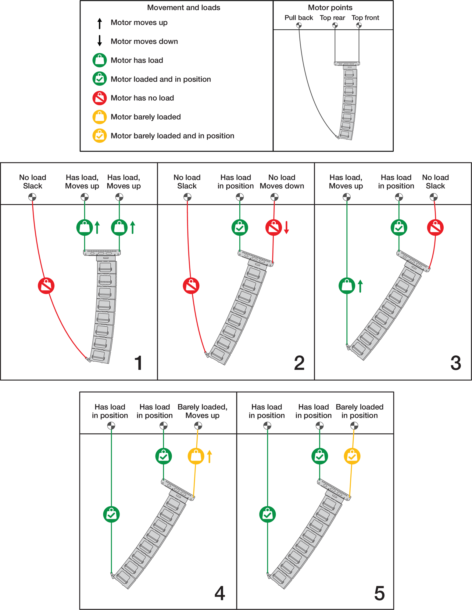
Transition to Pull Back Configuration Steps
Trim the array in its final position.
Raise the array to the designed trim height.
Note
The Reference Point, front or rear, is selected in MAPP. The front and rear Reference Points are located on the MG-PANTHER Shackle Bar.
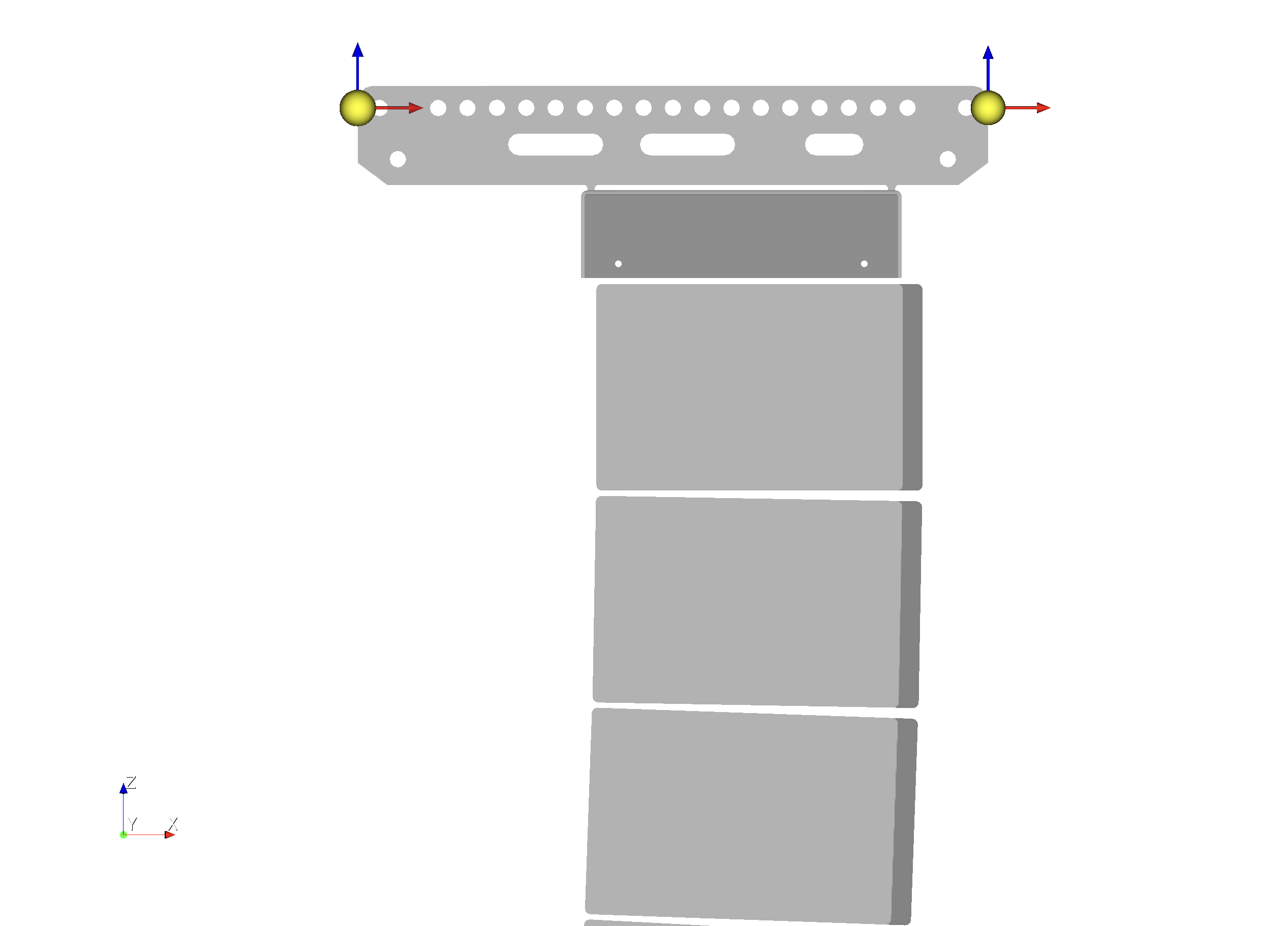
MAPP Front and Rear Reference Point Locations on MG‑PANTHER Shackle Bar.
If using an MVP Motor V Plate, adjust the tension of the connected hoists to rotate the array.
Verify and adjust as needed: height, grid angle, and horizontal rotation until the design parameters are achieved. Adjusting the grid angle
Note
When using one hoist or if most of the array weight is transferred to one hoist, the array may tend to rotate, changing the horizontal aim. In this case, use rigging hardware secured to the rigging elements of the array to prevent rotation.
Array Assembly Notes
Longer Arrays or Large Total Splay Angle
For arrays of 16 cabinets or smaller arrays with large splay angles it may not be possible to tip the suspended
cabinets enough to connect the rear GuideALink. If the rear hoist becomes slack before the center line of the bottom suspended cabinet is close to parallel to the working surface, use one of the following methods.
Rear GuideALinks Retracted
Option One
With the front GuideALinks connected, remove the white-on-gray LOCK quick-release pin from the bottom suspended cabinet.
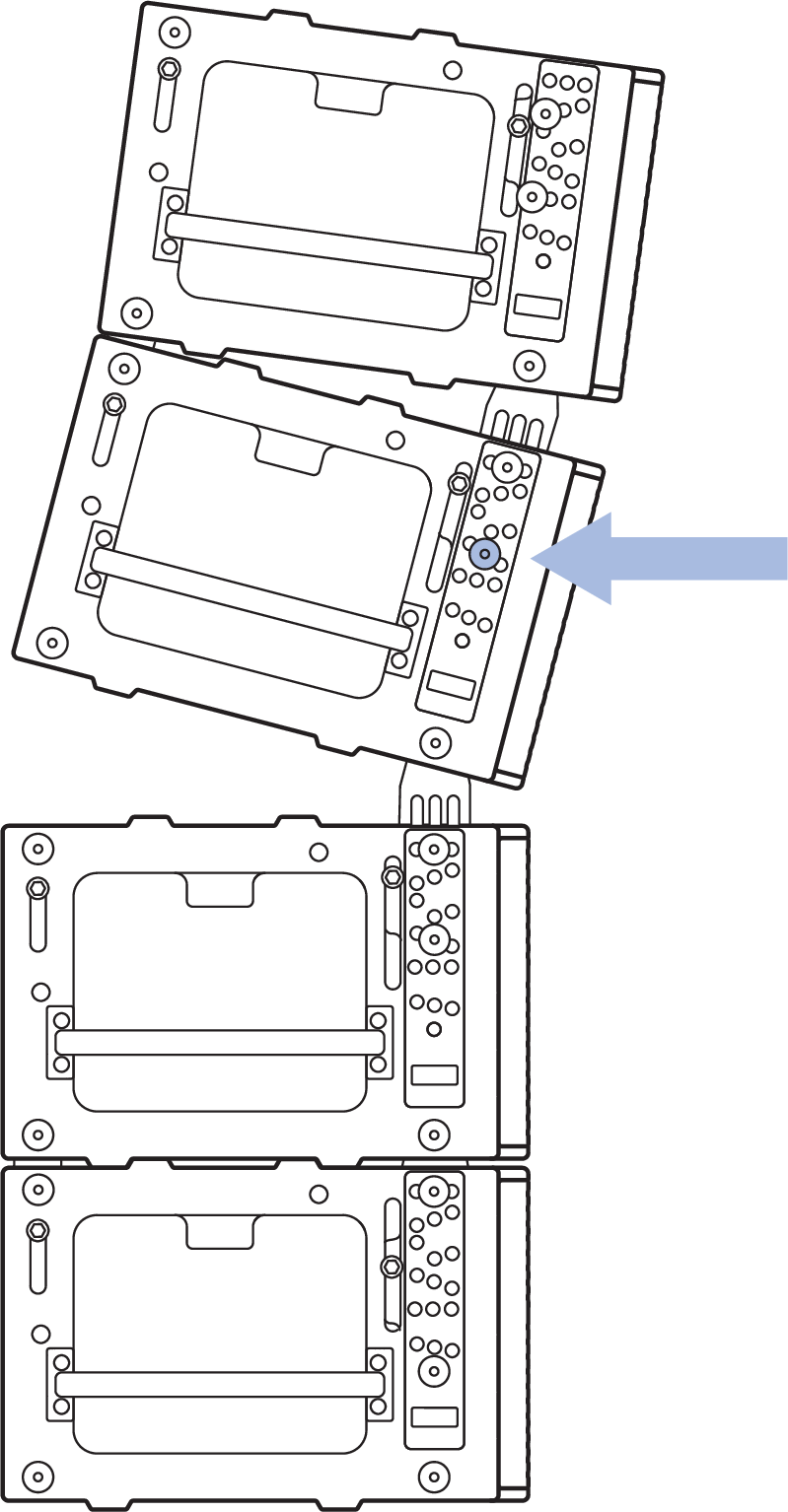
Remove Lock Pin of Bottom Suspended Cabinet
Lower the suspended cabinets and connect the rear GuideALink.
Lift the hoists and replace the previously removed white-on-gray LOCK quick-release pin.
Option Two
Set the front GuideALink gray-on-black ANGLE quick-release pin of the top stacked cabinet to 9 degrees, allowing it to fully extend. This maximizes the angle between the cabinets before the front edges of the cabinets collide.
With the caster frame attached and the front GuideALinks of the stacked cabinets connected to suspended cabinets, tension both hoists.
Raise the hoists until the front GuideALinks fully extend, with little of the weight supported by the caster frame wheels.
Hoists Lifting, Front GuideALinks Extend
Using the handles on both sides of the two cabinets closest to the working surface, pull the stack backwards while lowering the hoists. The gap at the rear of the suspended and stacked cabinets will close.
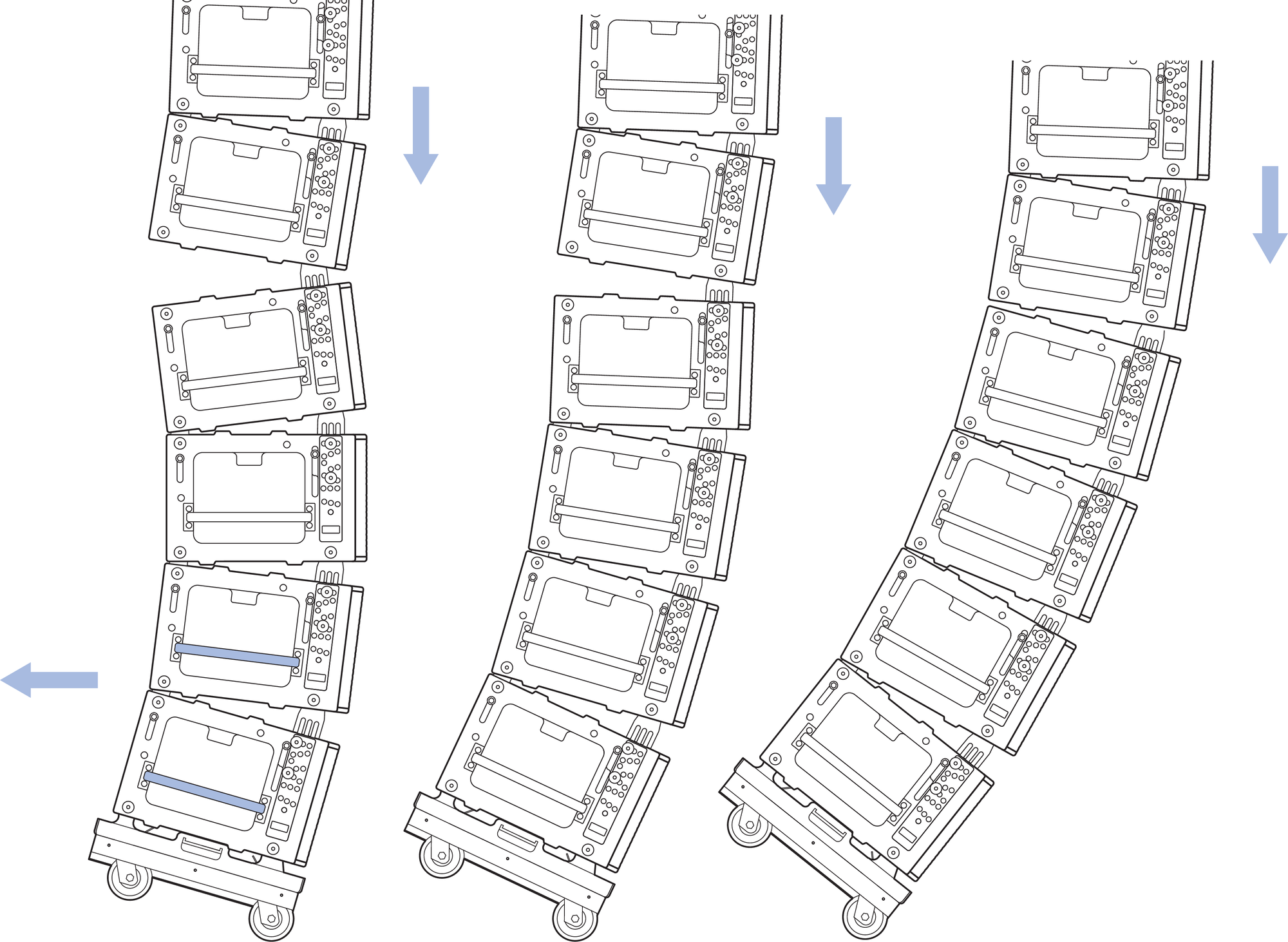
While Pulling the Stacked Cabinets Towards the Rear, Lower the Hoists.
Move the gray-on-black ANGLE quick-release pin that was previously moved to the 9 degree hole, back to its original hole.
Option Three
With the front GuideALinks connected, move the gray- on-black ANGLE quick-release pin of the top stacked cabinet to 9 degrees, allowing it to fully extend. This maximizes the angle between the cabinets before the front edges of the cabinets collide.
Raise the hoists enough to remove the caster frame, detaching the front first.
Connect the PBF-LYON Pull Back Frame to the bottom cabinet.
Connect the bridle of the PBF-LYON Pull Back Frame to a manual hoist connected to the utility point on the MG-PANTHER Shackle Bar.
Tension the hoist to close the gap in the rear between the suspended and stacked cabinets.
Move the gray-on-black ANGLE quick-release pin that was previously moved to the 9 degree hole, back to its original hole.
Attach PBF-LYON and Tension to Connect Rear GuideALink.
Inserting Quick Release Pins in LOCK Holes
If it is not easy to insert a white-on-gray LOCK quick- release pin due to the end frame and GuideALink holes not aligning, rotate the array so the line at the bottom of the front GuideALink label of that cabinet is parallel to the working surface, as shown in the figure below. Adjust the hoists in small increments up and/or down to align the GuideALink and the end frame holes as needed.
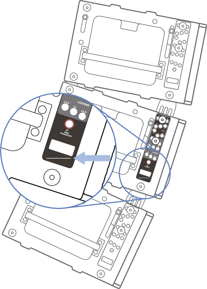
Label Alignment Line Parallel to Working Surface.
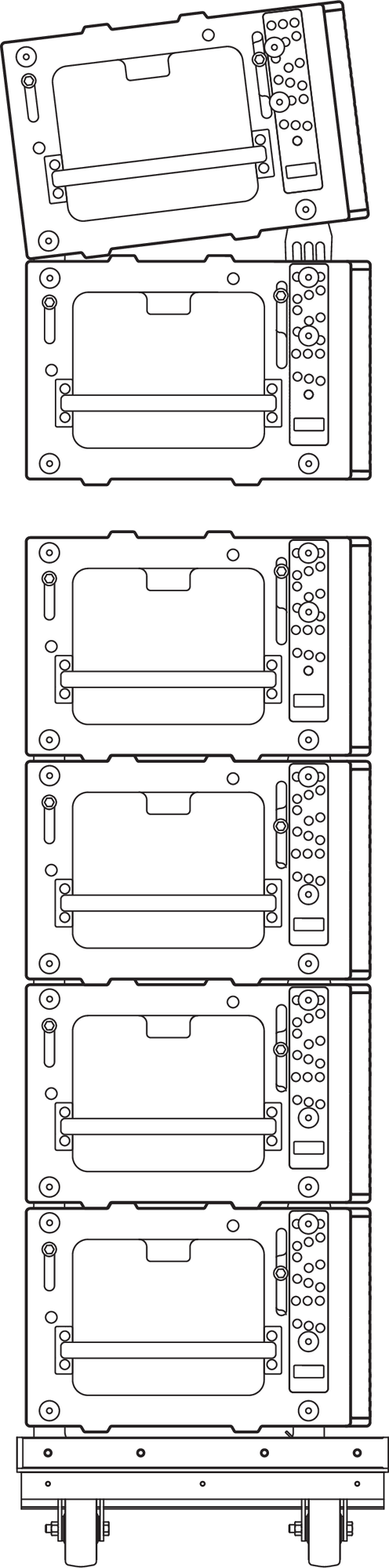
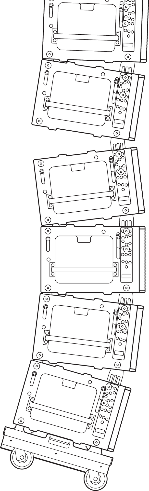
Stacking Caster Frames
The MCF-PANTHER caster frames can be stacked atop one another for storage. When stacking, tip the caster frame enough that all the wheels rotate the same direction, then lower the caster frame onto another.
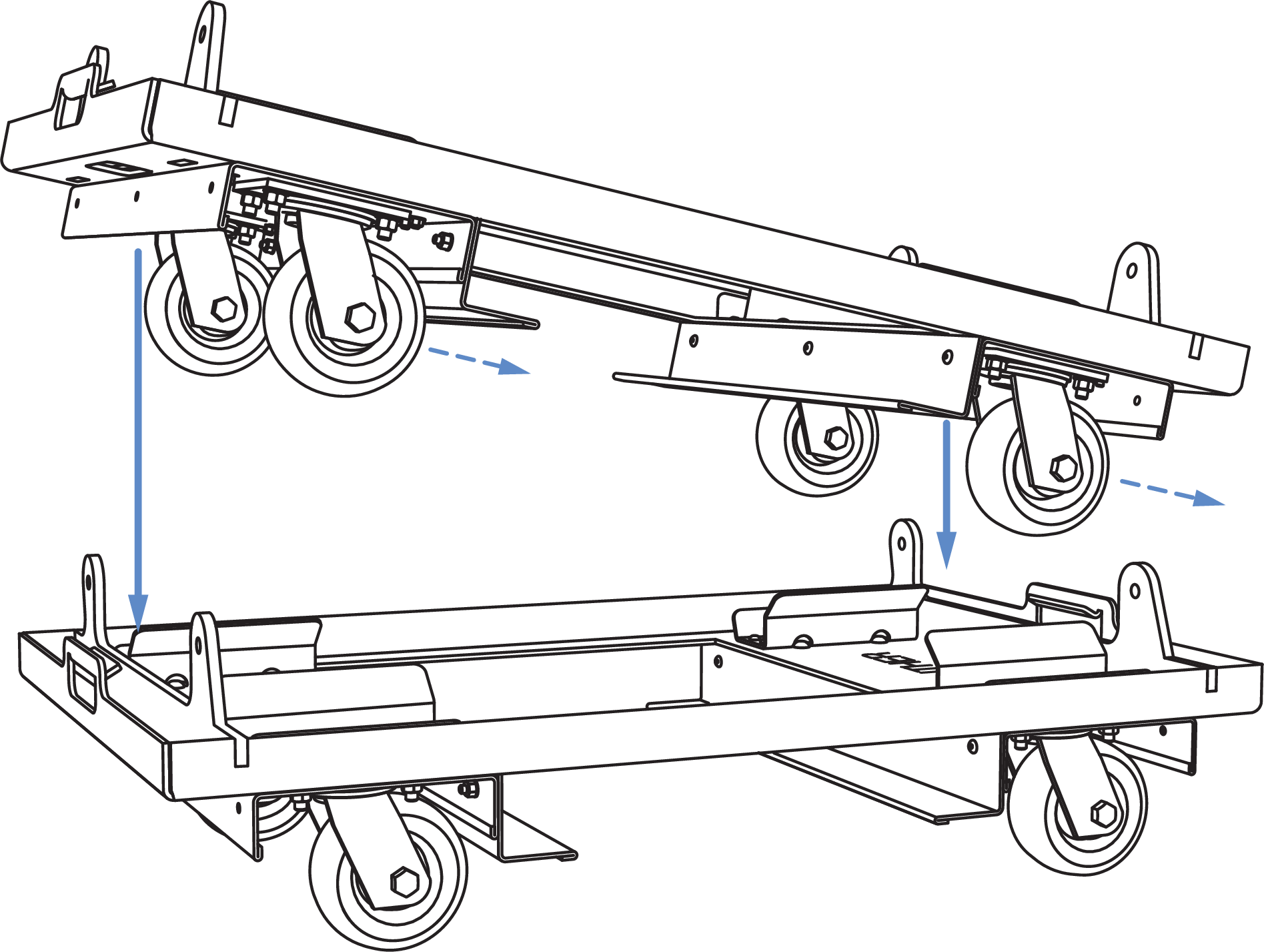
MCF-PANTHER Caster Frame Stacking, Tip to Rotate Casters, Lower to Stack
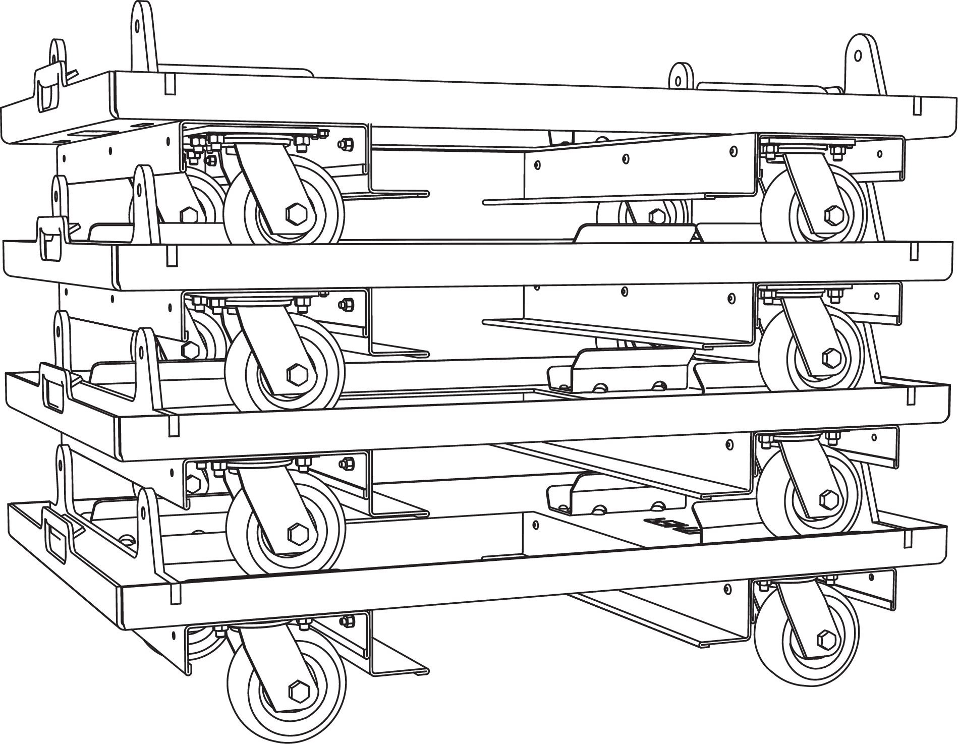
MCF-PANTHER Caster Frames Stacked
Outdoor Use
When deployed outdoors, it is common to secure the bottom of an array to structural points to prevent movement due to light wind.
It is typical to “land” arrays when there are high winds or when staff is not on site, e. g., overnight at a festival. When landing an array, protect the bottom front corner of the bottom PANTHER by either adjusting the array so the bottom PANTHER is parallel to the working surface or attaching an MCF-PANTHER Caster Frame.
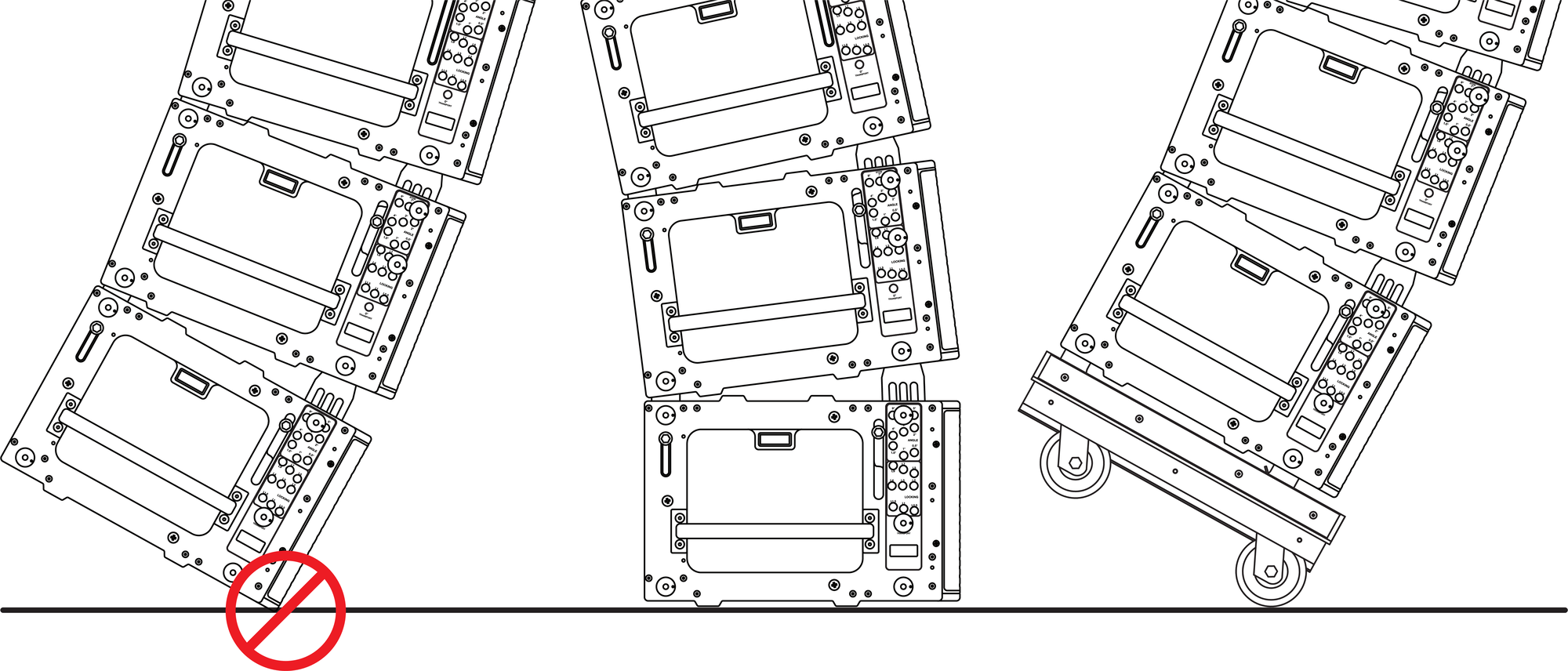
Only “Land” Array When Bottom Cabinet is Parallel to Surface or When Caster Frame is Attached