Installing Ashby Loudspeakers
This section provides procedures to install Ashby loudspeakers into ceilings, pendants, and suspended ceilings.
Meyer Sound Accessories
Meyer Sound provides several accessories to install Ashby loudspeakers.
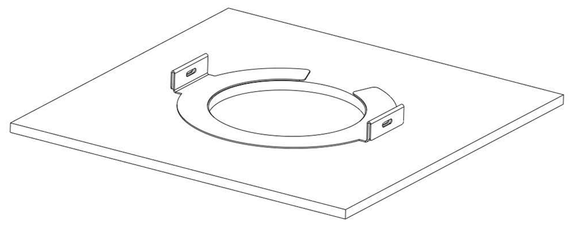
Tile C-Ring and Bridge Kit
The Tile C-Ring distributes the clamping force of the loudspeaker mounting clamps and is highly recommended on brittle ceiling surfaces. It can be used with or without the bridges (see below).
Use the following part numbers to order Tile C-Ring kits:
Ashby-8C Tile C-Ring: PN 40.260.130.01
Ashby-5C Tile C-Ring: PN 40.261.130.01
The C-Ring with Bridge Kit
The Tile C-Ring with Bridge Kit is used for suspended ceilings. The C-ring distributes the clamping force of the loudspeaker’s four mounting clamps and the bridges support and distribute the weight of the loudspeaker.
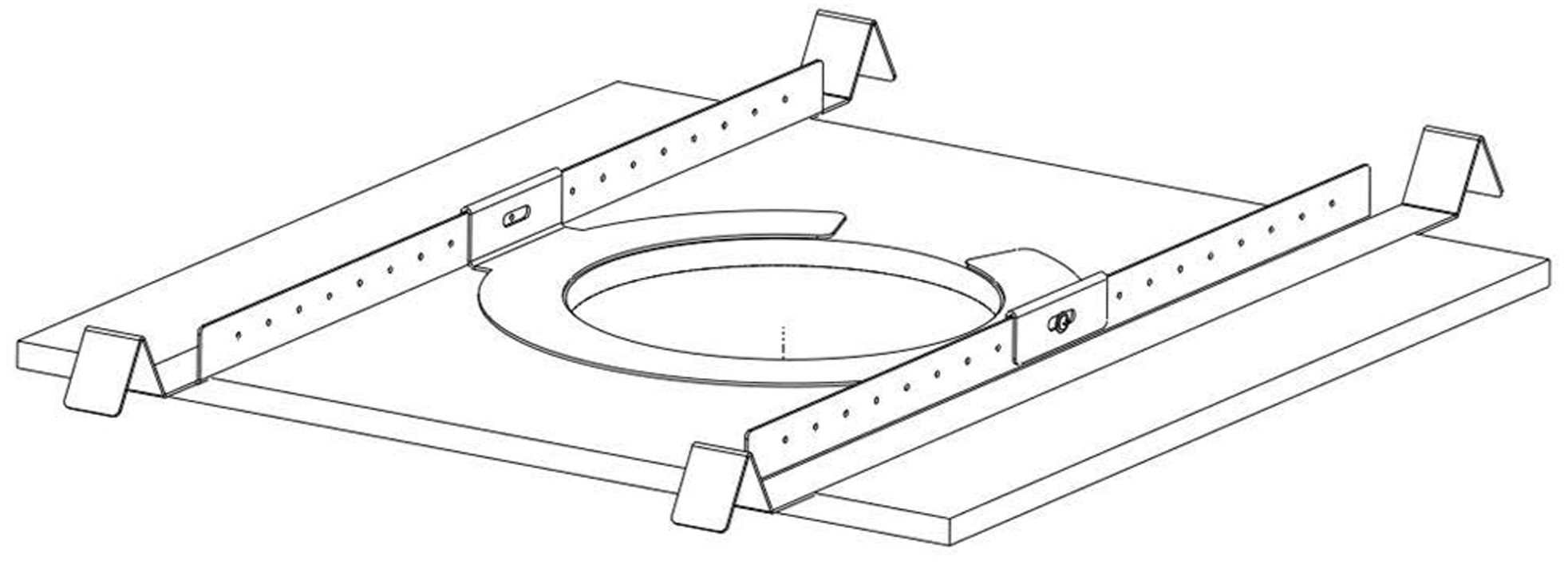
The C-Ring with Bridge Kit
Use the following part numbers to order C-Ring with Bridge Kits:
Ashby-8C Tile C-Ring with Bridge Kit: PN 40.260.131.01
Ashby-5C Tile C-Ring with Bridge Kit: PN 40.261.131.01
New Construction Bracket
This bracket can be fastened to the ceiling and acts as a template for ceiling cutout, ensuring a neat installation. The bracket fastens to the ceiling using #10 screws.
Use the following part numbers to order new construction bracket kits:
Ashby-8C New Construction Bracket: PN 40.260.140.01
Ashby-5C New Construction Bracket: PN 40.261.140.01
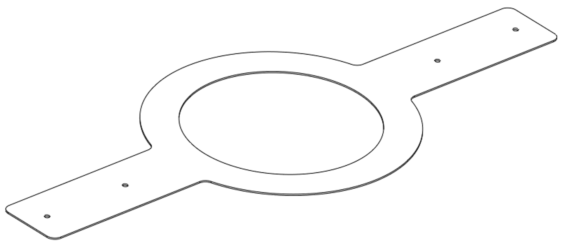
New construction bracket
Meyer Sound Pendant
The Meyer Sound pendant allows Ashby loudspeakers to hang from ceilings where a flush mount is not practical. These elegant pendant enclosures utilize a minimalistic design typically used in pendant lighting to blend discreetly into the environment.
The pendant holds an Ashby loudspeaker inside without requiring extra hardware using the same grille as a ceiling-mounted Ashby to maintain a consistent appearance.
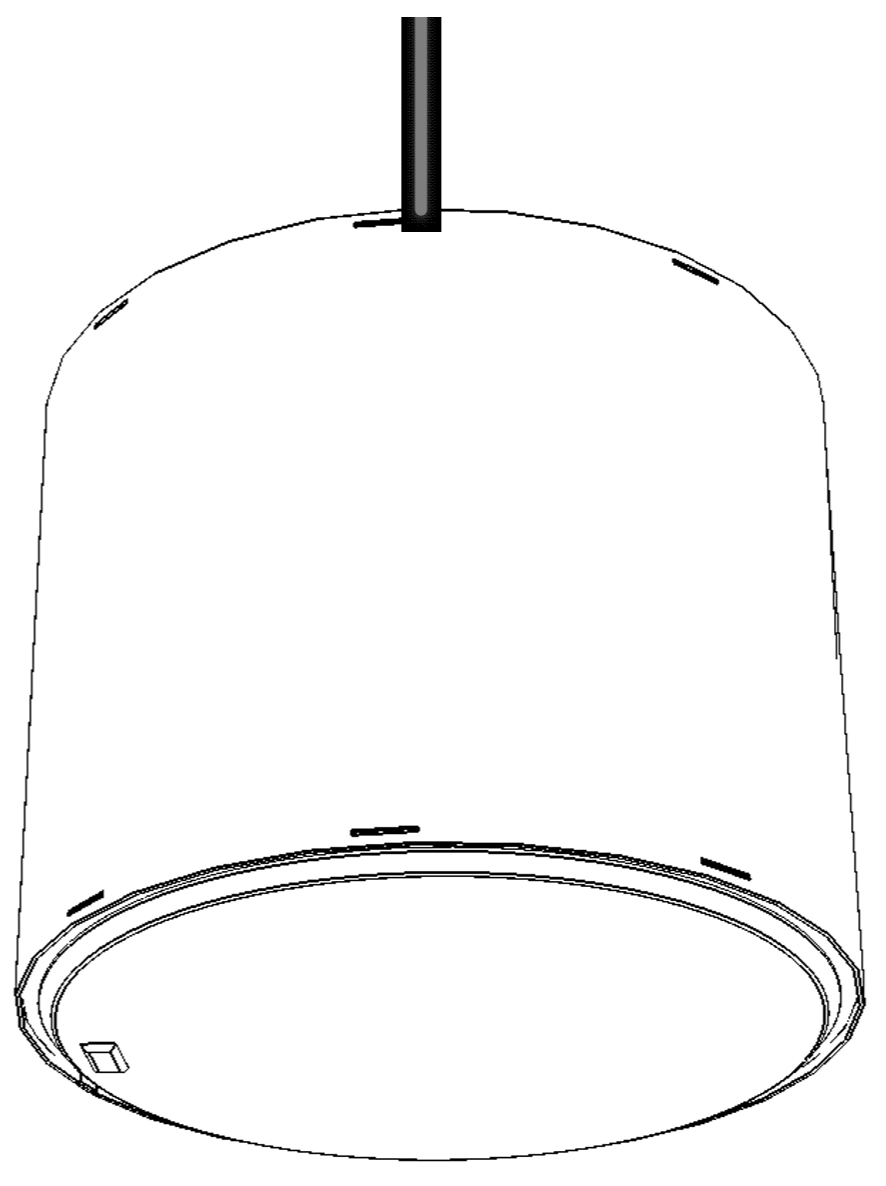
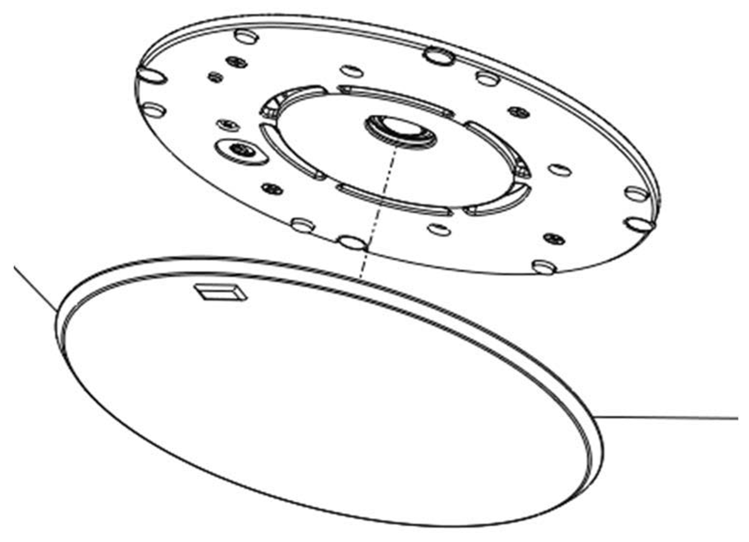
Ashby Pendant
The pendant includes a top cover to hide the back of the loudspeaker and wiring connectors making them perfect for installations where they may be viewed from above. The top cover includes:
Holes with protection grommets for cables;
A center hole for a threaded rod;
Three tabs for steel wires (not included) for a single hang point. The tabs must be bent up before use.
The Ashby-5C and Ashby-8C have separate pendant models.
Use the following part numbers to order Ashby pendant kits:
Ashby-8C Pendant: PN 40.260.030.01
Ashby-5C Pendant: PN 40.261.030.01
Ashby Wiring
The loudspeaker provides a strain relief fitting for bare wires, 1/2-in flexible metal conduit, or 1/2-in 14 NPSM threaded conduit adapters.
Prepare the wires.
For bare wires or conduit without a threaded conduit adapter, open the wiring cover, loosen the L-bracket screws, and remove the clamping screws.
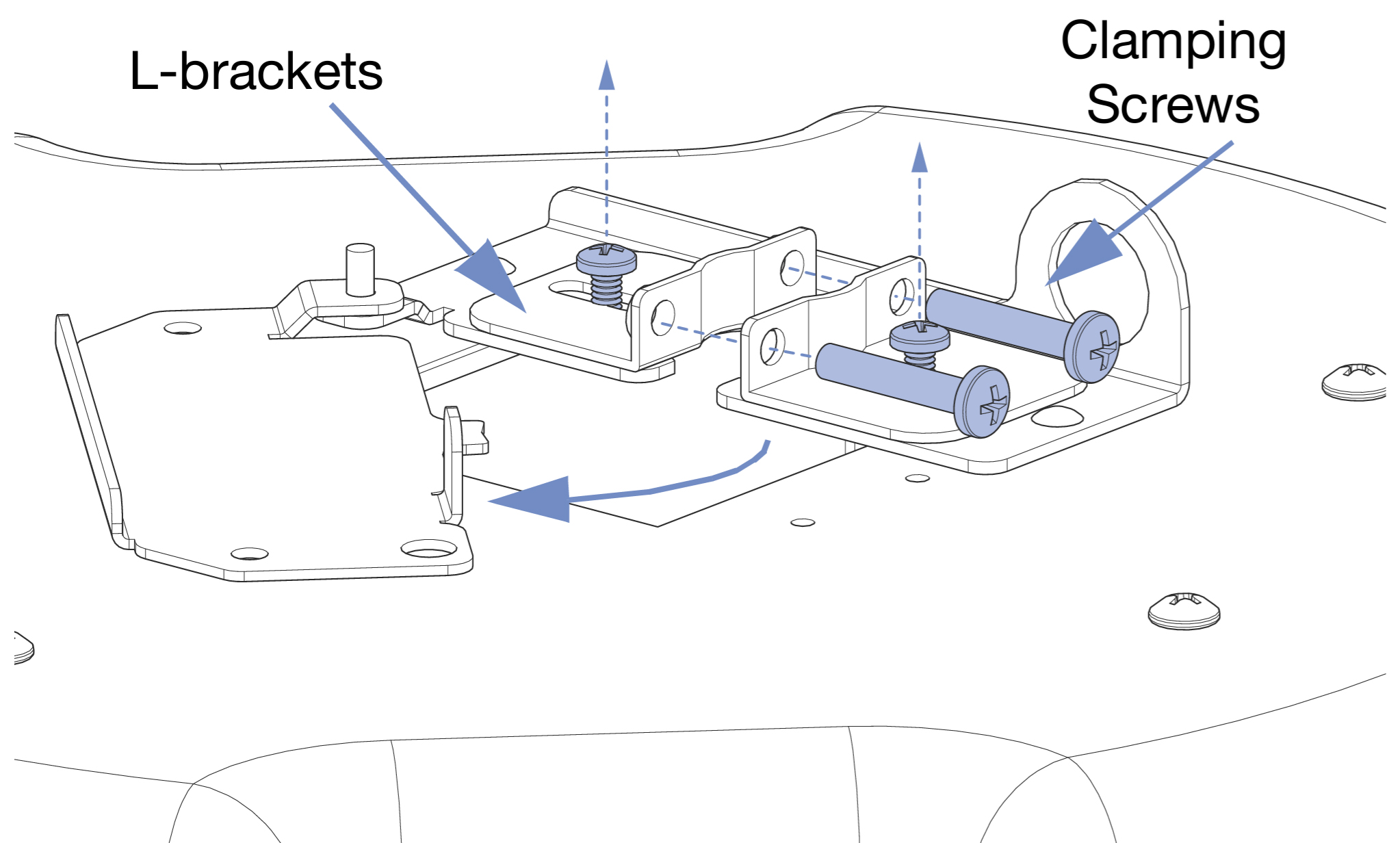
Close and latch the wiring cover, and clamp the wire or conduit with the L-brackets. Tighten the L-bracket and clamping screws.
Insert the cable or 1/2-in flexible metal conduit into the input or looping connector and feed the wires through the L-bracket opening.
Close and latch the wiring cover, and clamp the wire or conduit with the L-brackets. Tighten the L-bracket and clamping screws.
Clamping the wire
Open the wiring cover and completely remove the L bracket screws, L brackets, and clamping screws.
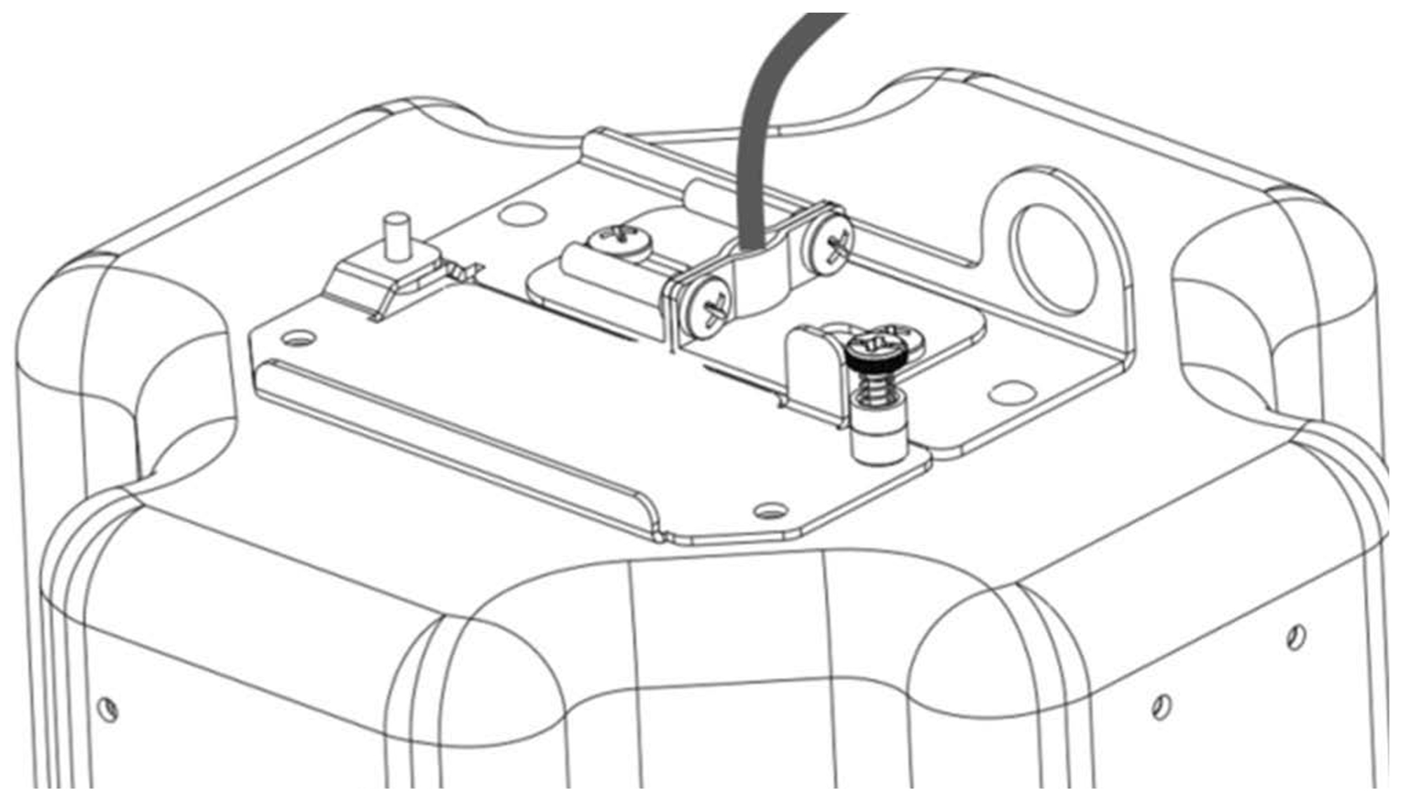
Install the threaded adapter, insert the conduit, and connect the wires.
Close and latch the wiring cover.
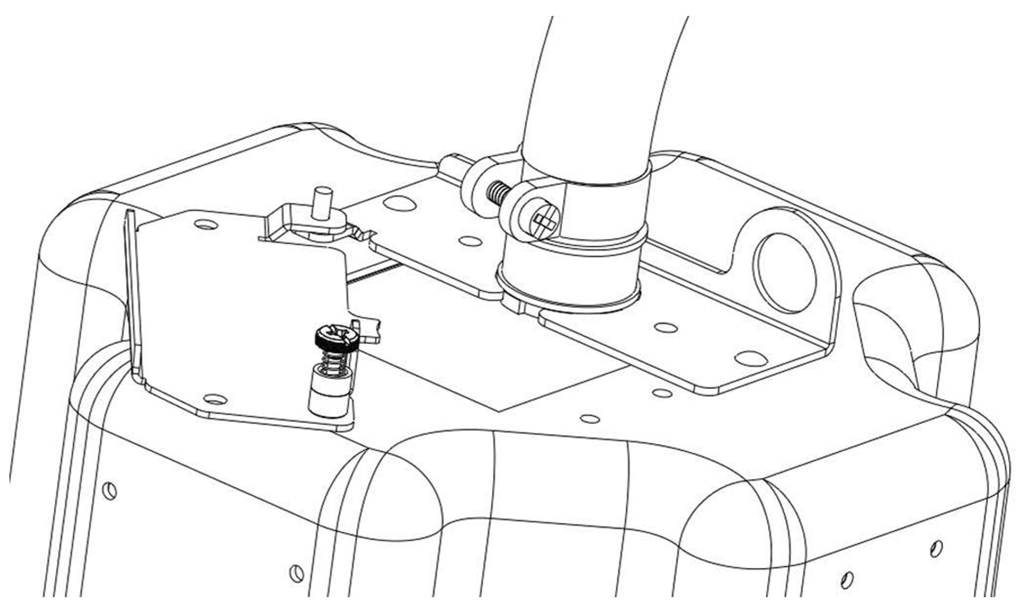
Clamping a conduit
Installing into a Standard Ceiling
Locate the desired position of the loudspeaker and mark its center on the ceiling.
Use the template provided with the loudspeaker to align the hole in the center of the template with the mark.
Trace the perimeter of the template with a pencil.
Cut along the traced circle on the ceiling and remove the cutout disc.
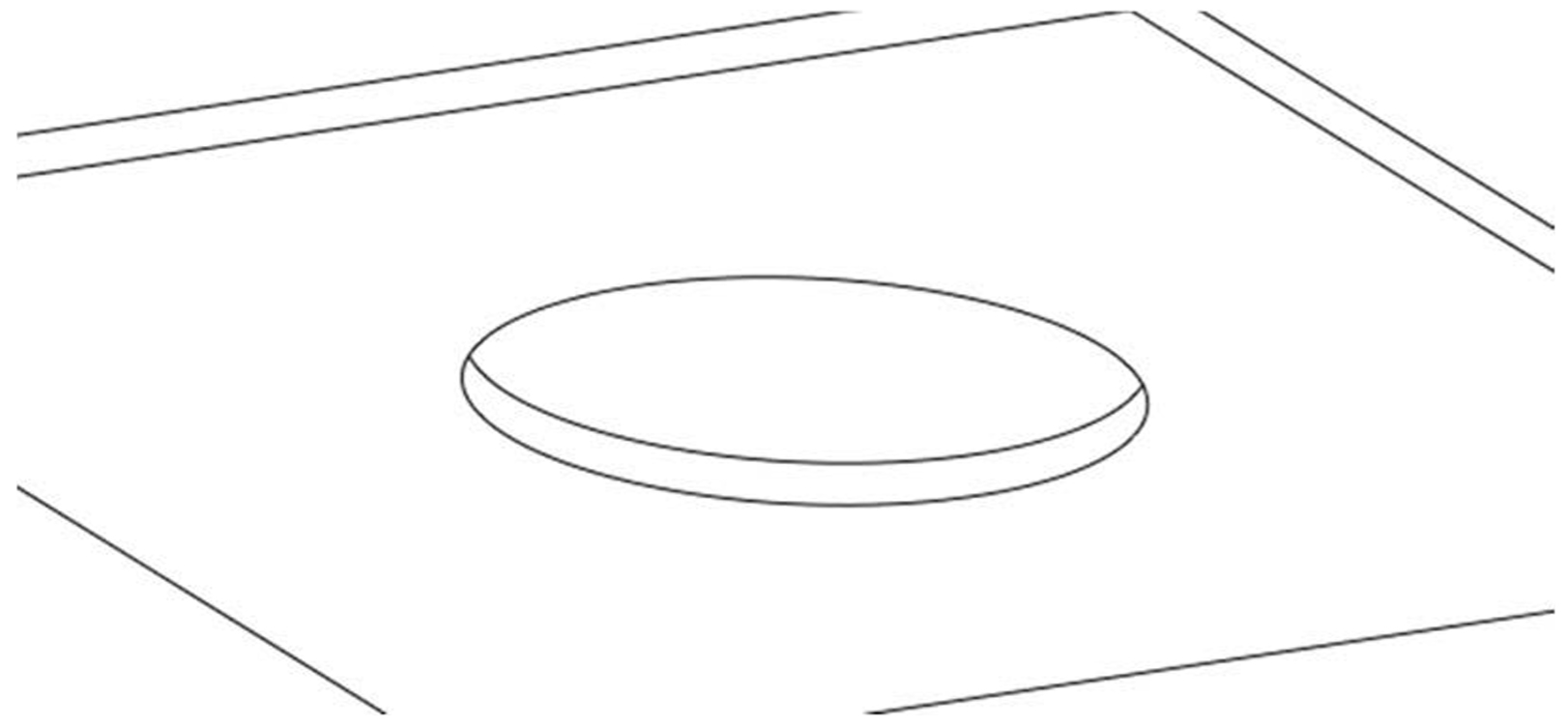
Cutting a hole in the ceiling with the template provided
Install the loudspeaker into the ceiling and hold flush to the ceiling.
Make sure the loudspeaker's clamps are flush with the loudspeaker to allow it to pass freely into the ceiling.
Note
if desired or required, a safety lanyard can be attached to the loudspeaker with a carabiner before inserting the loudspeaker into the ceiling (see below).
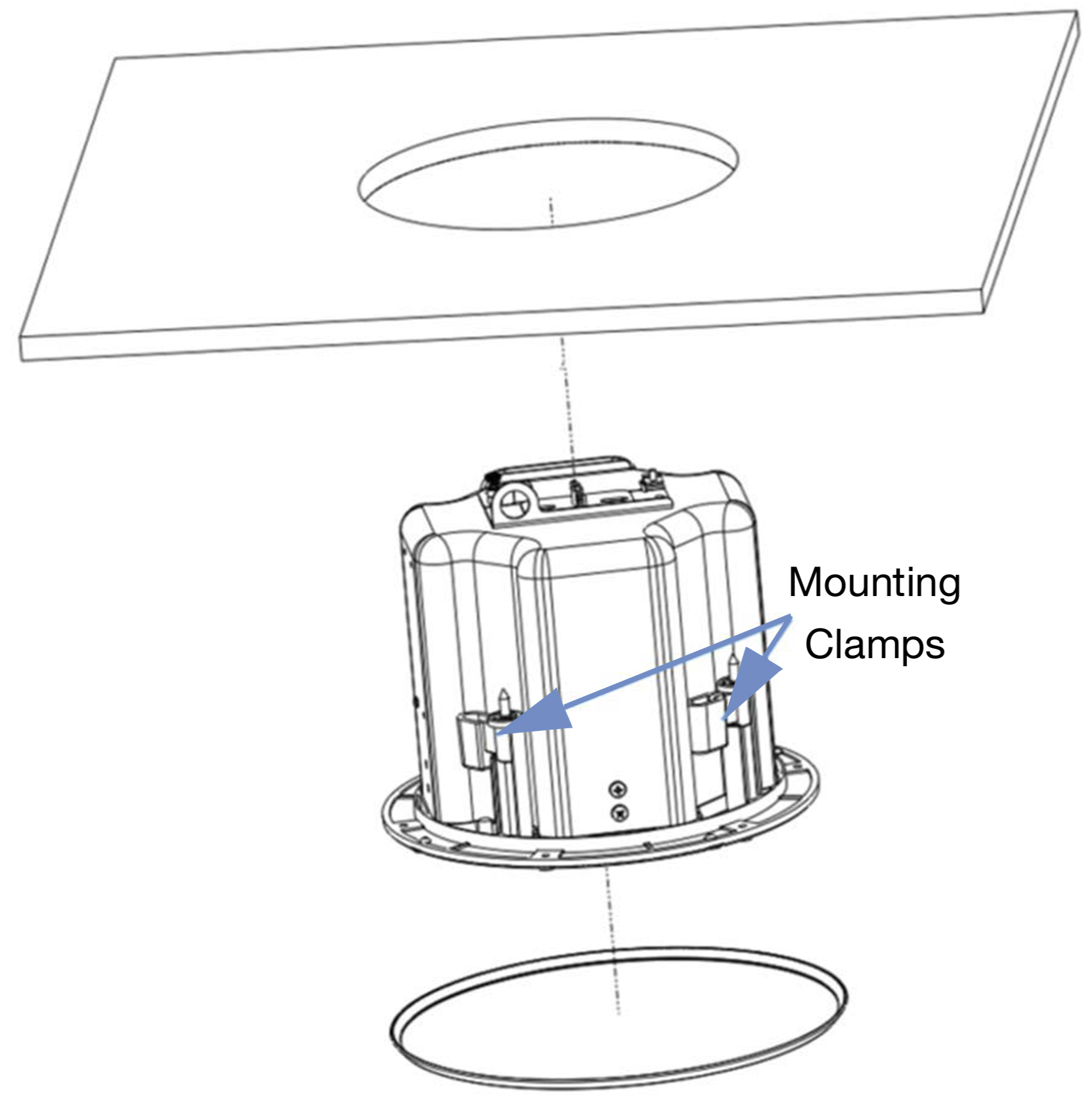
Inserting the loudspeaker into the ceiling
Use a #2 Phillips screwdriver to torque the four screws to hold the loudspeaker in place.
Caution
Do not over-tighten! If using a powered screwdriver, set the torque to 0.8 N-m (7 in-lbs). if the screwdriver torques out, slowly increment the torque setting until the mounting clamps begin to move.
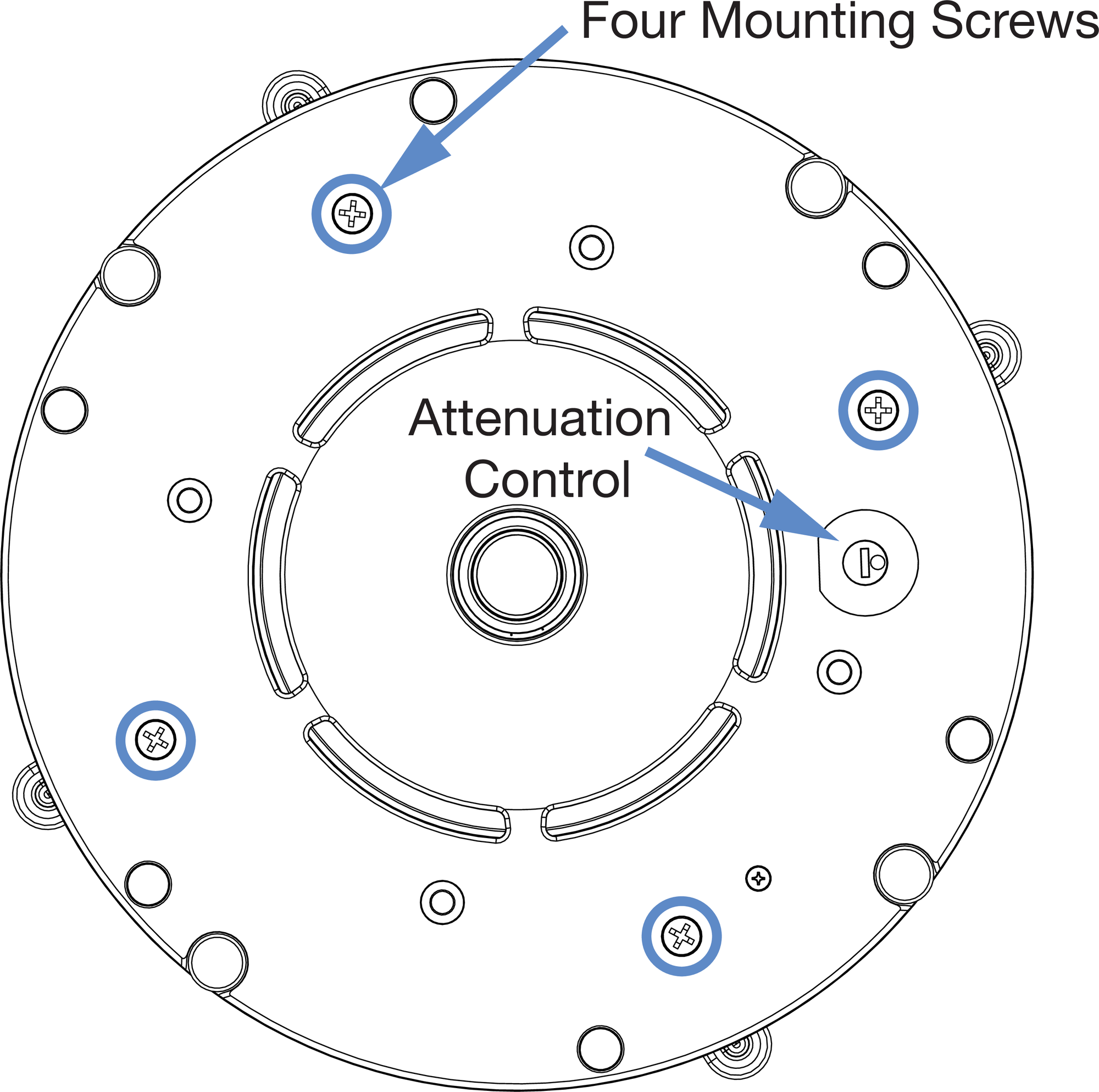
Ashby-5C (top) and Ashby-8C (bottom) loudspeaker mounting clamp screws and Attenuation Selector
Before placing the grille frame on the loudspeaker, choose an attenuation setting (if the loudspeaker has this feature).
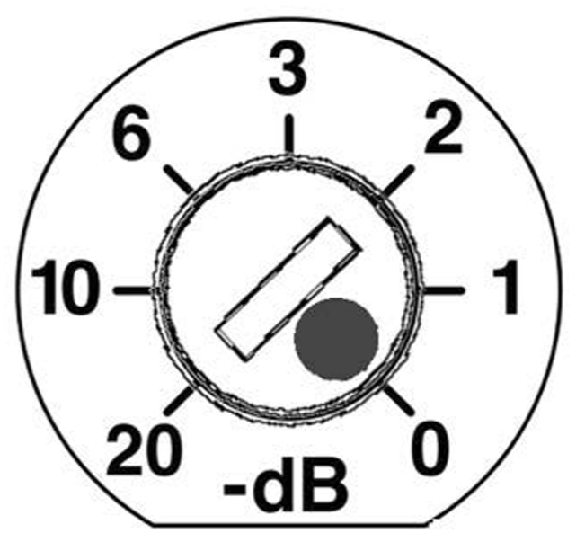
Attenuation Selector
Place the loudspeaker grille on the installed loudspeaker.
Make sure to line up the grille with the magnets on the loudspeaker.
Placing the loudspeaker grille on the loudspeaker
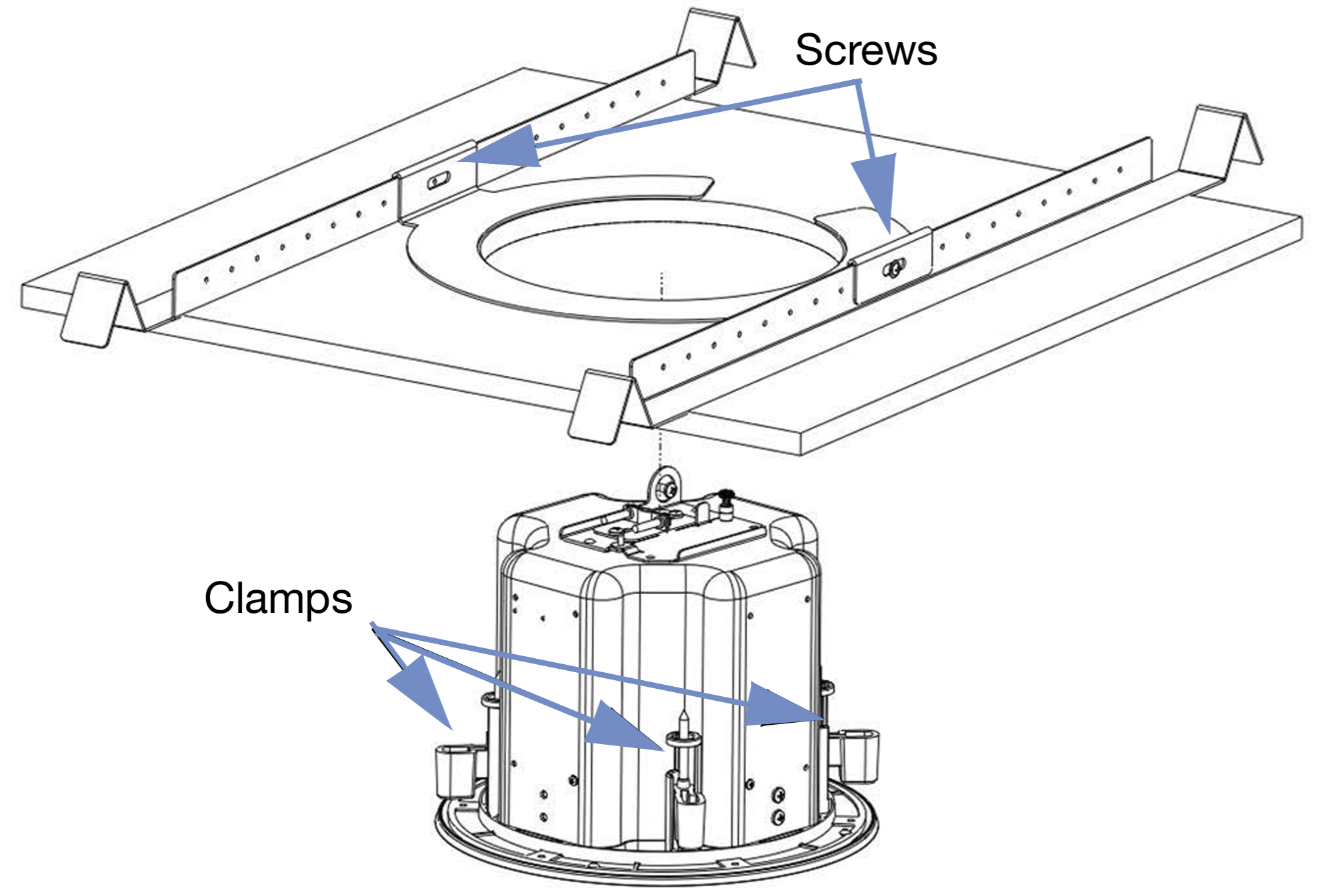
Installing into a Suspended Ceiling
Assemble the C-ring with tile bridge in the ceiling.
Slide the C-ring on the tile bridge until it is centered with the hole.
Install washers and #6 sheet metal screws (included) into the C-ring and tighten into place.
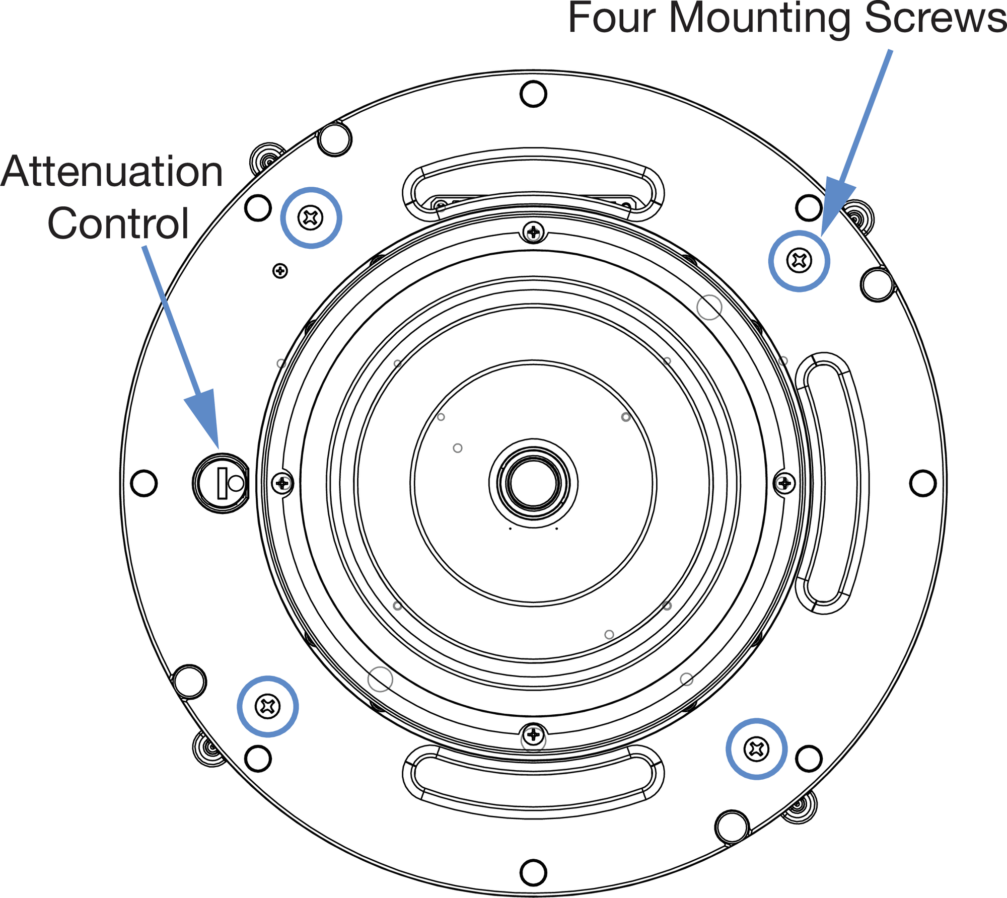
Install the loudspeaker by tightening the four mounting screws on the bezel of the loudspeaker to clamp it to the C-ring.
Ashby-5C (top) and Ashby-8C (bottom) loudspeaker mounting clamp screws and Attenuation Selector
Note
The tile bridge acts as a fail-safe if the tile gets damaged, so it may not contact the railings.
 |
Installing the loudspeaker into a bridge in the ceiling
Safety Lanyard
Some construction codes require a secondary support system. Ashby loudspeakers have a built-in attachment point for a load-rated carabiner with lanyard (neither included) to safely support the weight of the loudspeaker.
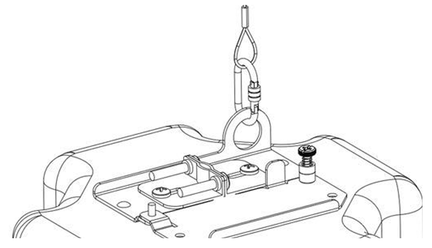
Attaching a safety lanyard for secondary support
Installing into a High Ceiling with the Pendant
The pendant is designed to replicate flush-mounted ceiling installations, utilizing the four integrated clamps, and thus do not require extra hardware.
Remove the loudspeaker grille and make sure that the clamps are away from the front of the bezel and locked in the open position.
Attach the supplied lanyard using the supplied hardware onto the loudspeaker to act as a secondary support.
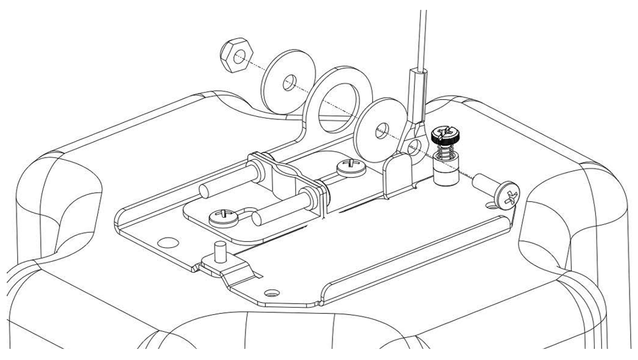
Attaching a safety lanyard
Insert wires through the grommets and attach them to the Ashby connector panel.
Slide the lanyard through one of the holes.
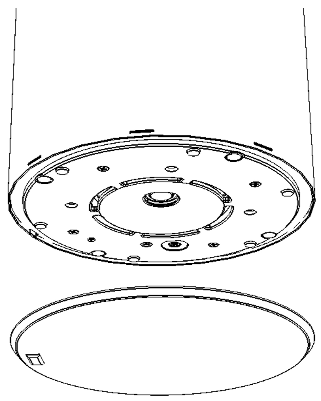
Insert the Ashby loudspeaker inside the pendant and rotate the four Phillips head screws clockwise to engage the loudspeaker clamps to the pendant.
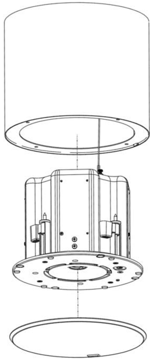
Installing an Ashby loudspeaker into a Meyer Sound pendant
Lock the loudspeaker securely into place by tightening the mounts until the loudspeaker is flat against the pendant.
Caution
Do not over tighten! If using a powered screwdriver, set the torque to 0.8 N-m (7 in-lbs). if the screwdriver torques out, slowly increment the torque setting until the mounting clamps begin to move.
Attach the lanyard to a secondary support point
Before placing the grille frame, adjust the attenuation control to choose an attenuation setting, if the loudspeaker has this feature.
Ashby-5C (top) and Ashby-8C (bottom) loudspeaker mounting clamp screws and Attenuation Selector
Place the loudspeaker grille on the installed loudspeaker.
Fitting the grille frame onto an Ashby loudspeaker in a pendant
Equalization for Pendant Installation
Ashby-8C and Ashby-5C are optimized for ceiling mounting (infinite baffle) and require some filters to achieve flat response when mounted in a pendant or free-air. These filters simulate the infinite baffle effect of the ceiling.
The simplest solution is to use a minimum-phase U-Shaping filter found in GALAXY processors.The filter is a low frequency shelf with a 580 Hz breakpoint and 6 dB/octave slope. The gain is +6 dB for the Ashby-8C and +8 dB for the Ashby-5C.
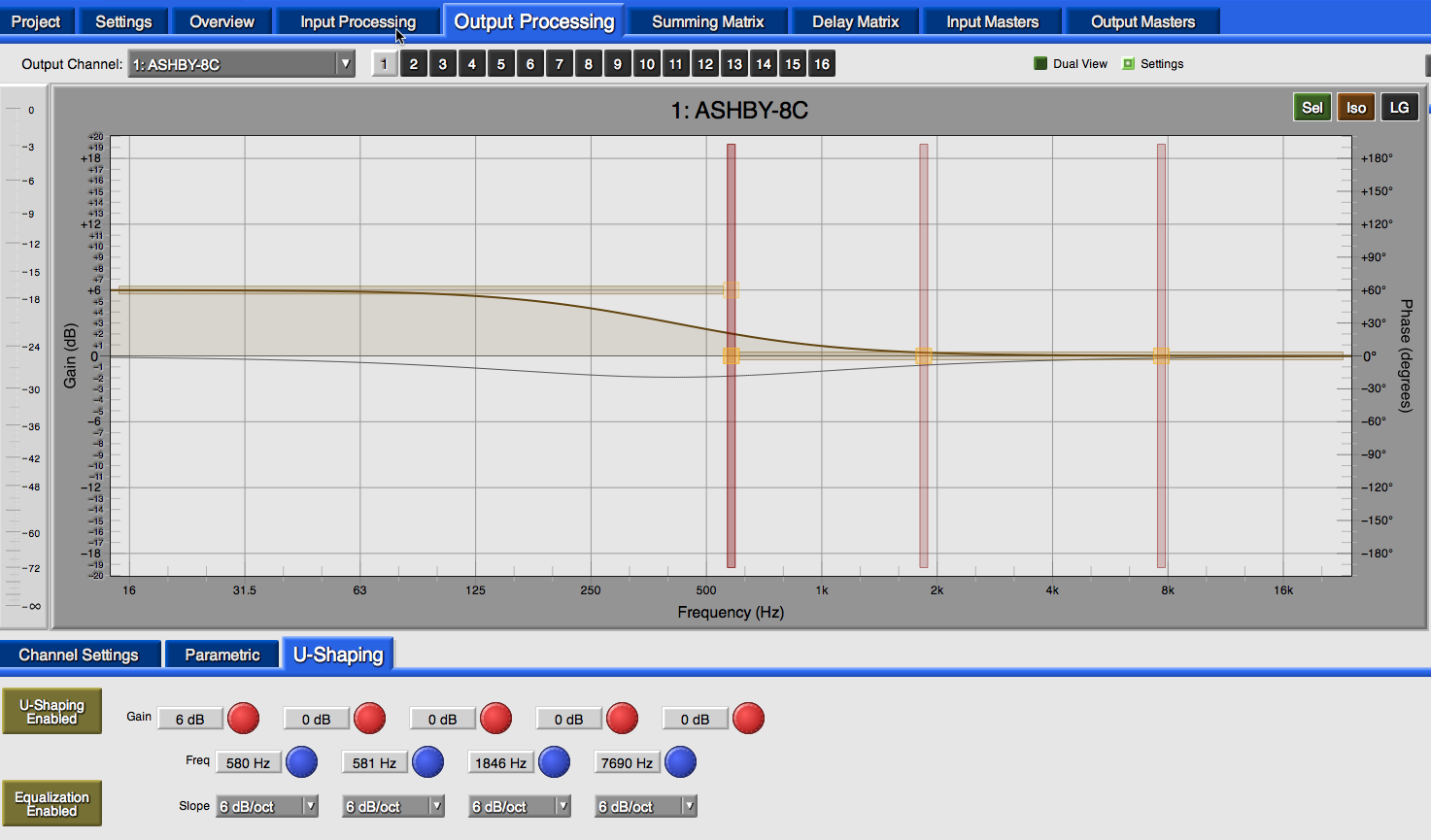
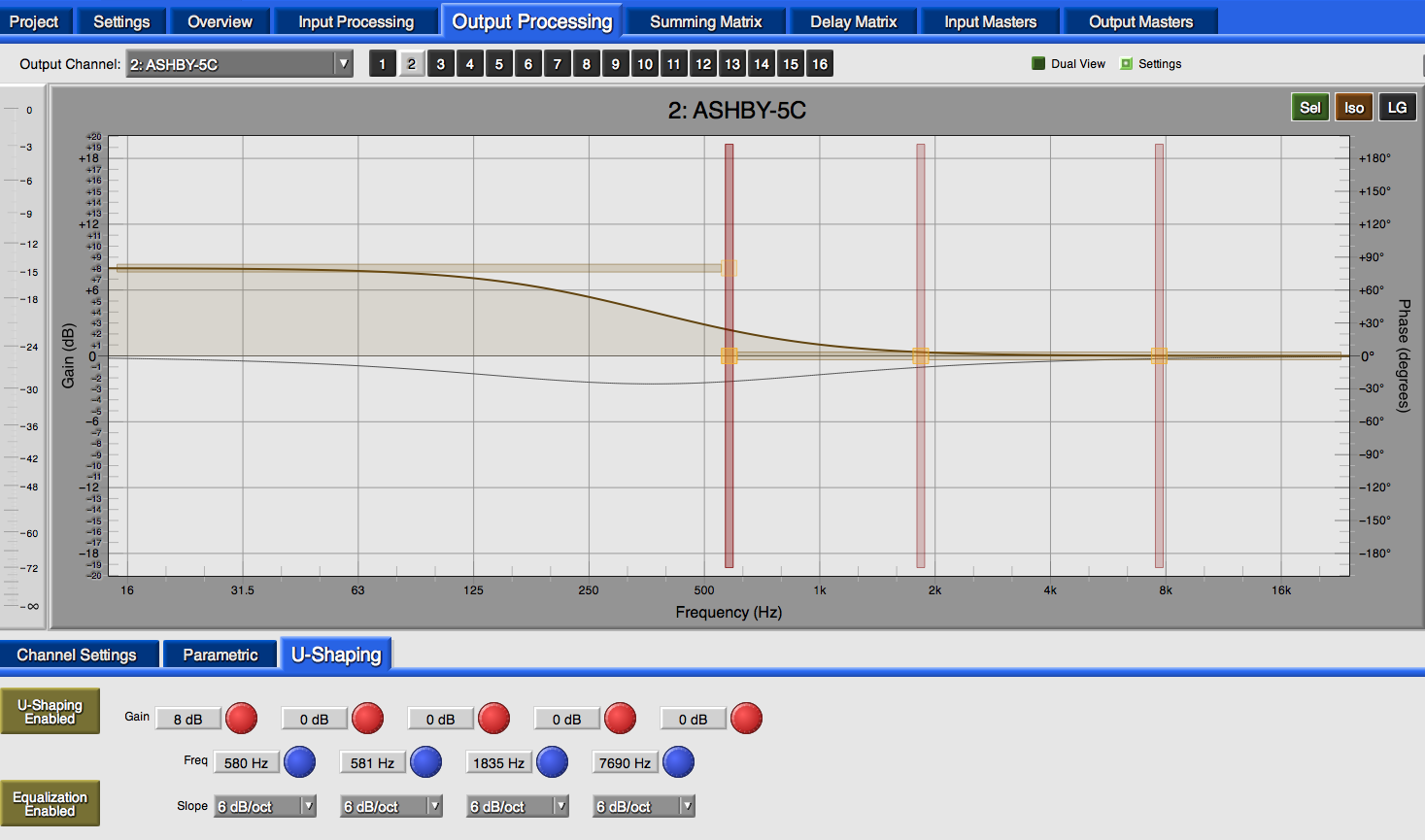
Filter settings Ashby-8C (top) and Ashby-5C (bottom)