The MM-4XP Connectors
The MM-4XP receives DC power and balanced audio from an EN3 5-pin male connector on its rear panel. The connector’s five pins include two for DC power (negative and positive) and three for balanced audio (shield, negative, and positive). To function properly, the MM-4XP requires 48 V of DC power.
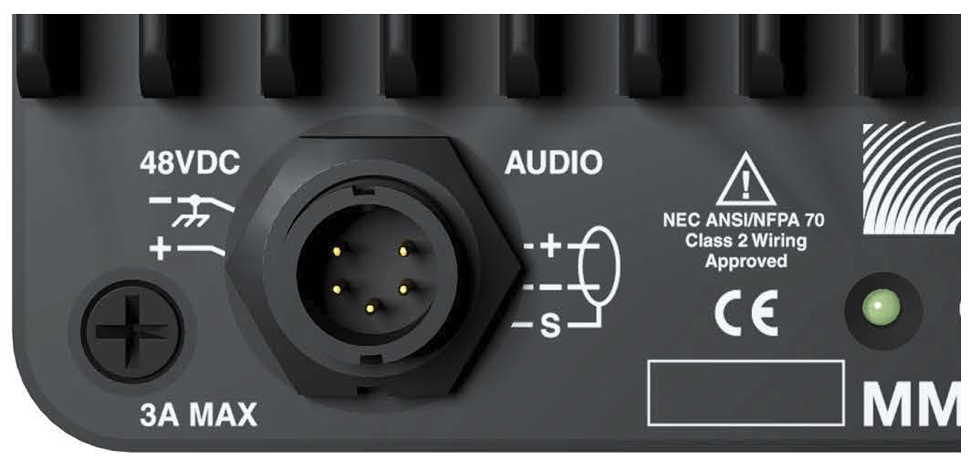 |
MM-4XP Connector
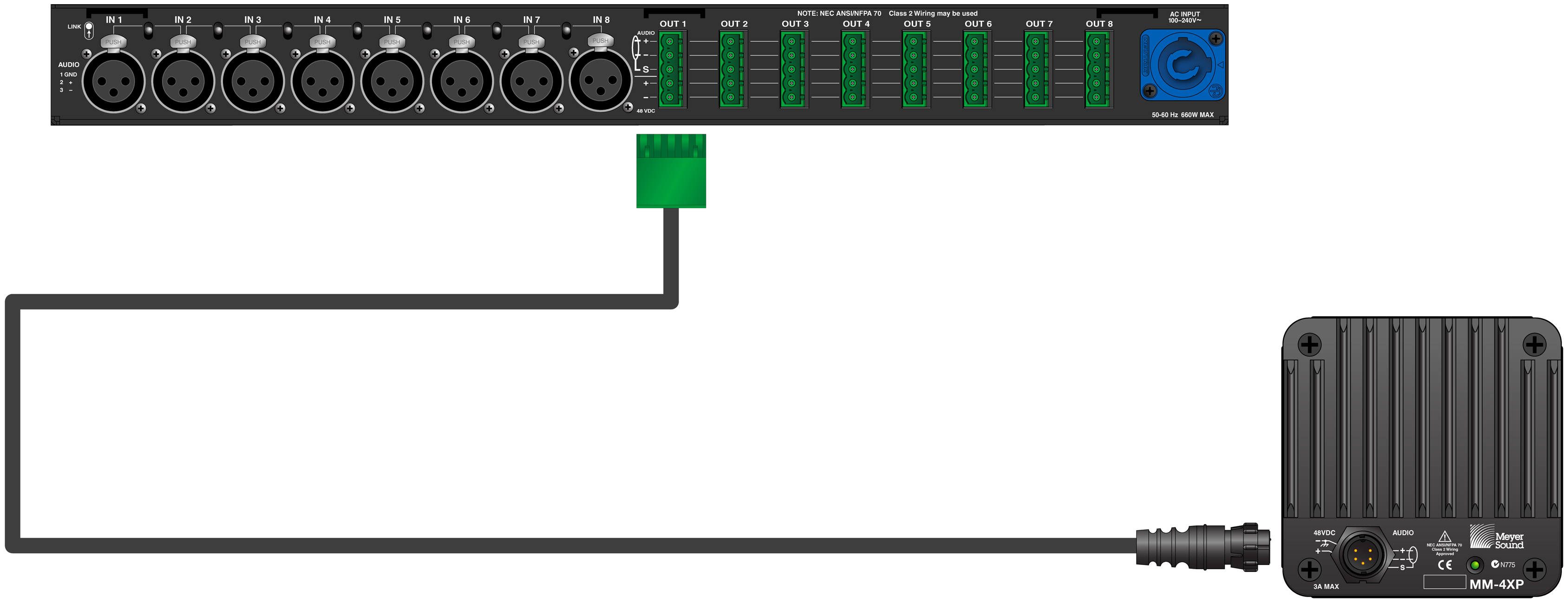
A single composite cable (such as Belden 1502) wired for both DC power and balanced audio can be used to connect the MM-4XP to one of the MPS-488’s eight or the MPS- 482’s two channel outputs.
Wiring the EN3-to-Pigtail Cables
Each MM-4XP loudspeaker comes with one EN3 5-pin female to pigtail cable. The EN3 end of the cable connects directly to the MM-4XP connector. The pigtail end of the cable can be equipped with either an EN3 5-pin male connector for connecting to the MPS-488HPE power supply, or a Phoenix 5-pin female connector for connecting to the MPS-488HPP or MPS-482HP power supplies. The pigtail can also be spliced to a longer loudspeaker cable or to a junction box. The included EN3-to-pigtail cable uses Belden 1502 cable, which can be wired for both DC power and balanced audio. The EN3-to-pigtail cable is available in plenum or regular (non-plenum) versions.
Note
For a complete list of cables and cable connectors available from Meyer Sound that can be used with the MM-4XP loudspeaker, see MM-4XP Accessories.
When assembling MM-4XP loudspeaker cables with the included EN3-to-pigtail cables, make sure to use the wiring scheme in Table 1. The red and black wires in Belden 1502 cable have a thicker gauge than the other three wires and should be used for DC power. The blue, white, and shield wires should be used for audio.
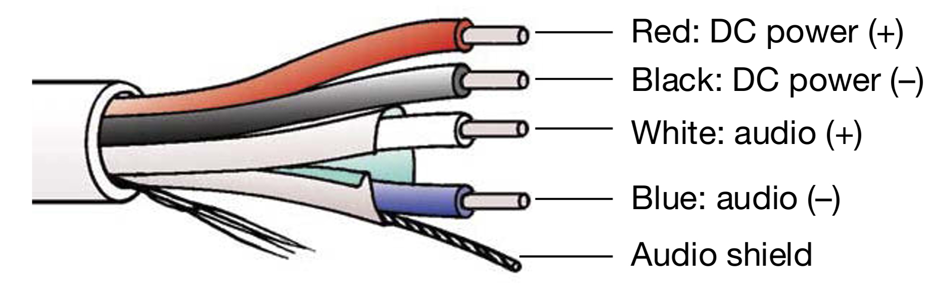 |
Belden 1502 Composite Cable
Note
For details on assembling MM-4XP loudspeaker cables, see Assembling Loudspeaker Cables.
Wire | Gauge | Signal |
|---|---|---|
Red | 18 AWG | DC power, positive (+) |
Black | 18 AWG | DC power, negative (–) |
White | 22 AWG | Balanced audio, positive (+) |
Blue | 22 AWG | Balanced audio, negative (–) |
Shield | 24 AWG | Balanced audio, shield |
When wiring MM-4XP cables, it is extremely important that each pin in the cable be wired so that the pins in the MM-4XP connector align with those in the MPS channel output connector (see “Channel Outputs”). Make sure the 48 V DC from the MPS power supply is wired directly (and only) to the 48 V DC pins on the MM-4XP connector, and that the polarity is observed (negative to negative, positive to positive) to avoid damage to the loudspeaker. In addition, make sure the audio pins are wired correctly; polarity reversals for audio signals can affect system performance.
Note
For information on MM-4XP cable requirements, see MM-4XP Current Draw and Cable Requirements.
MM-4XP Current Draw and Cable Requirements
Each MM-4XP loudspeaker draws a maximum current of 0.7 A rms and 2.2 A peak from the 48 V DC output of the MPS power supply. The current draw for the MM-4XP is dynamic and fluctuates as operating levels change. The cabling between the MM-4XP and the MPS power supply adds resistance and hence causes a voltage drop at the loudspeaker. Because lower voltages compromise peak SPL, and in some cases frequency response, cable resistance should be minimized.
Note
When connecting an MM-4XP to an MPS channel output, the total cable resistance should not exceed 4 ohms.
Cable Lengths and Cable Gauges for MM-4XPs
When connecting an MM-4XP to an MPS channel output, you can use cable lengths of up to 300 feet with only 1 dB of peak SPL loss using 18 AWG wire. Longer cable lengths are possible with heavier wire gauges (see tables MM-4XP Loudspeaker Cable Lengths (AWG) and MM-4XP Loudspeaker Cable Lengths (European) below).
Note
For music playback at moderate levels (when the MM-4XP is not driven to maximum output), cable lengths of up to 500 feet with 18 AWG wire are acceptable.
Cable Gauge | Resistance (Ω/ft) | Approximate Max. Length |
|---|---|---|
12 AWG | 0.0016 | 1200 ft |
14 AWG | 0.00253 | 750 ft |
16 AWG | 0.00402 | 475 ft |
18 AWG | 0.00636 | 300 ft |
20 AWG | 0.01008 | 175 ft |
Cable Gauge | Resistance (Ω/m) | Approximate Max. Length |
|---|---|---|
2.50 mm2 | 0.0052 | 365 m |
1.50 mm2 | 0.01076 | 175 m |
1.00 mm2 | 0.02087 | 90 m |
0.75 mm2 | 0.03307 | 55 m |
The maximum cable length for an MM-4XP can be calculated with the following formula:
maximum length = 4 Ω / 2 * cable resistance (in Ω/ft)
For example, the maximum length of an 18 AWG cable with a resistance of 0.00636 Ω/ft is equal to 314.4 feet
(4 Ω/ 2 * 0.00636 Ω/ft).
Note
For long cable runs, you can use large cable gauges for most of the run and then terminate with the included EN3-to-pigtail cable.
The MM-4XP LED
The MM-4XP has a three-color LED on its rear panel that changes color to indicate the loudspeaker’s status.
Powering On (Green)
When powering up the MM-4XP loudspeaker, the following startup events occur and are indicated by the LED:
The LED flashes green and then yellow during power up.
The LED turns solid green indicating the loudspeaker is ready to reproduce audio.
Caution
If the MM-4XP LED turns red and stays solid red after powering up and the audio is muted, the loudspeaker has encountered a failure and may need to be serviced. Contact Meyer Sound Technical Support.
If the MM-4XP LED turns solid red and the loudspeaker continues to output audio, though at reduced levels, the loudspeaker’s voltage may have dropped below 25 V DC. Operation of the loudspeaker under these conditions is not recommended and the loudspeaker’s power supply and cabling should be verified.
Limiting (Yellow)
Limiting activity is indicated when the MM-4XP LED turns yellow. When engaged, the limiter protects the loudspeaker’s driver and prevents signal peaks from causing excessive distortion in the loudspeaker’s amplifier, thereby preserving headroom and maintaining smooth frequency response at high levels. When the level returns to normal, below the limiter’s threshold, the LED turns green and limiting ceases.
The MM-4XP performs within its acoustical specifications at normal temperatures when the MM-4XP LED is green, or if the LED turns yellow for two seconds or less and then turns green for at least one second. If the LED remains yellow for longer than three seconds, that loudspeaker enters hard limiting where:
Increases to the input level have no effect.
Distortion increases due to clipping and nonlinear driver operation.
The driver is subjected to excessive heat and excursion, which will compromise its life span and may eventually lead to damage over time.
Caution
The MM-4XP LED turns yellow when the loudspeaker’s signal goes 2 dB beyond the actual onset of limiting, and indicates a safe, optimum level has been exceeded. If the MM-4XP loudspeakers in a system begin to limit before reaching the required SPL, consider adding more loudspeakers to the system to achieve the desired SPL without exposing the loudspeakers to excessive levels and possible overheating.
Loudspeaker Temperature and Limiting
The MM-4XP LED turns solid yellow when the temperature of the MM-4XP heatsink reaches 65° C (145° F), indicating the unit is reaching its maximum heat dissipation, and a reduction in SPL is recommended. While the MM-4XP will continue to operate while the LED is yellow, the limiter threshold is lowered to a safe level (causing the output level to be lowered by 6 dB) to prevent the loudspeaker from overheating. When the temperature of the MM-4XP heatsink cools to 50 °C (122 °F), the LED changes from yellow to green and the limiter threshold returns to normal.
Clipping (Red)
The MM-4XP LED flashes red when its input signal causes the amplifier to overload. If the LED flashes red continuously, the loudspeaker is severely overloaded and a reduction in the input level is recommended.
Caution
If the MM-4XP LED turns solid red and the loudspeaker continues to output audio, though at reduced levels, the loudspeaker’s voltage may have dropped below 25 V DC. Operation of the loudspeaker under these conditions is not recommended and the loudspeaker’s power supply and cabling should be verified.
Connecting MM-4XP Loudspeakers to a Meyer Sound Power Supply
Power off the MPS power supply.
Connect audio sources (from a mixer or processor) to the MPS channel inputs. Use balanced XLR cables.
Use the MPS link switches to route channel inputs to the desired channel outputs.
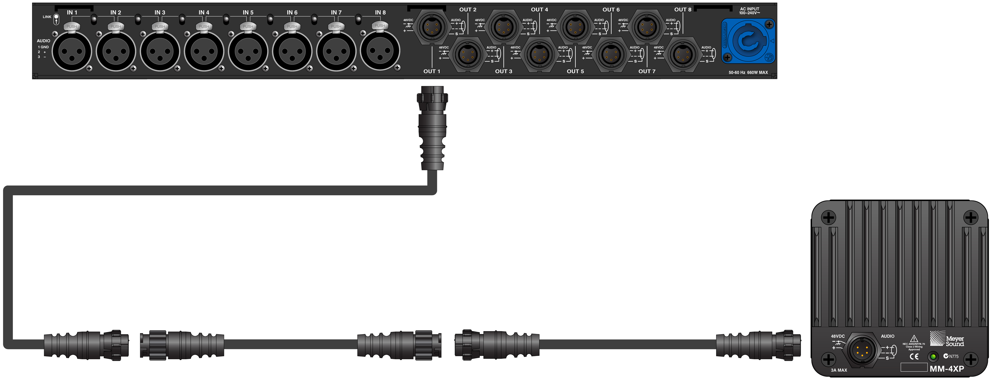
Connect the MM-4XP loudspeakers to the MPS channel outputs. Use a composite cable (such as Belden 1502) wired for both DC power and balanced audio and outfitted with the appropriate connector:
For an MPS-488HPP or MPS-482HP power supply, use an EN3 5-pin female to Phoenix 5-pin female cable.
For an MPS-488HPE power supply, use an EN3 5-pin female to EN3 5-pin male cable.

To join two cables, one with an EN3 5-pin male cable mount connector to one with an EN3 5-pin female cable mount connector, use an EN3 5-pin female-to-male cable coupler (PN 28.163.033.01).
Caution
Make sure the MM-4XP loudspeaker cables are wired correctly. For details on assembling loudspeaker cables, see Assembling Loudspeaker Cables.
Power on the MPS power supply and monitor the LEDs on the front panel to verify connections (for more information, see Voltage and Load Current LEDs.
Check the MM-4XP LEDs on the rear panel and verify they are green (ready to reproduce audio).
Enable output from the audio sources (from the mixer or processor) connected to the MPS power supply.