Amplification and Audio
The Acheron drivers are powered by a two-channel proprietary Meyer Sound amplifier with MOSFET output stages. The audio signal is processed with an electronic crossover, correction filters for phase and frequency response, and driver protection circuitry. Each channel has peak and rms limiters that prevent driver over-excursion and regulate the temperature of the voice coil.
The Acheron rear panel has an audio Input and Loop output connector, Limit LEDs, and an optional RMS module for connecting to the RMS remote monitoring system (see The RMS Remote Monitoring System).
Audio Connectors
The Acheron and Acheron LF include female XLR Input and male XLR Loop output connectors.
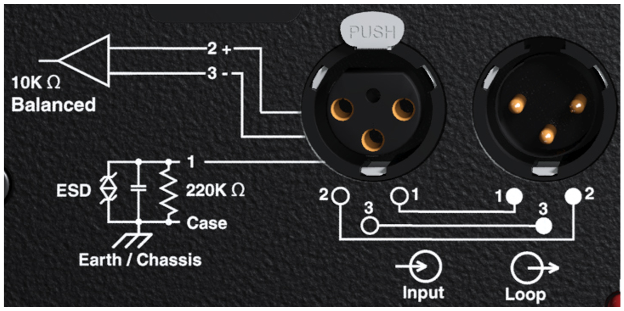 |
Acheron Audio Connectors, Input and Loop Output
Input Connector
The female XLR Input connector accepts a balanced audio signal with an input impedance of 10 kOhm. The connector uses the following wiring:
Pin 1 — 220 kOhm to chassis and earth ground (ESD clamped)
Pin 2 — Signal (+)
Pin 3 — Signal (–)
Case — Earth (AC) ground and chassis
Pins 2 and 3 carry the input as a differential signal. Pin 1 is connected to earth through a 220 kOhm, 1000 pF, 15 V clamped network. This circuitry provides virtual ground lift for audio frequencies while allowing unwanted signals to bleed to ground. Make sure to use standard, balanced XLR audio cables with all three pins connected on both ends.
Telescopic grounding is not recommended, and shorting an input connector pin to the case may cause a ground loop, resulting in hum.
Tip
If unwanted noise or hiss is produced by the loudspeaker, disconnect its input cable. If the noise stops, there is most likely nothing wrong with the loudspeaker. To locate the source of the noise, check the audio cable, source audio, and AC power.
Loop output connector
The male XLR Loop output connector allows Acheron and Acheron LF loudspeakers to be looped from a single audio source. For applications that require multiple Acherons and Acheron LFs, connect the Loop output of the first unit to the Input of the second, and so forth.
Note
The order in which loudspeakers are connected when looping audio signals is unimportant. The Loop connector is wired in parallel to the Input connector and transmits the unbuffered source signal even when the Acheron is powered off.
To avoid distortion when looping multiple Acherons, make sure the source device can drive the total load impedance of the looped loudspeakers. In addition, the source device must be capable of delivering approximately 20 dBV (10 V rms into 600 ohms) to yield the maximum peak SPL over the entire operating bandwidth of the loudspeakers. Most professional audio equipment can transmit these source levels.
To calculate the load impedance for the looped loudspeakers, divide 10 kOhms (the input impedance for a single Acheron) by the number of looped loudspeakers. For example, the load impedance for 10 Acheron loudspeakers is 1000 ohms (10 kOhms / 10). To drive this number of looped loudspeakers, the source device should have an output impedance of 100 ohms or less. This same rule applies when looping Acheron loudspeakers with other self-powered Meyer Sound loudspeakers and subwoofers.
Note
Most source devices are capable of driving loads no smaller than 10 times their output impedance.
Caution
Make sure that all cabling for looped loudspeakers is wired correctly (Pin 1 to Pin 1, Pin 2 to Pin 2, and so forth) to prevent the polarity from being reversed. If one or more loudspeakers in a system have reversed polarity, frequency response and coverage will be significantly degraded.
Limiting
Acheron loudspeakers employ Meyer Sound’s advanced TruPower® limiting. Conventional limiters assume a constant loudspeaker impedance and set the limiting threshold by measuring voltage alone. This method is inaccurate because loudspeaker impedances change as frequency content in the source material changes, and as thermal values for the loudspeaker’s voice coil and magnet vary. Consequently, conventional limiters often begin limiting prematurely, which reduces system headroom and dynamic range.
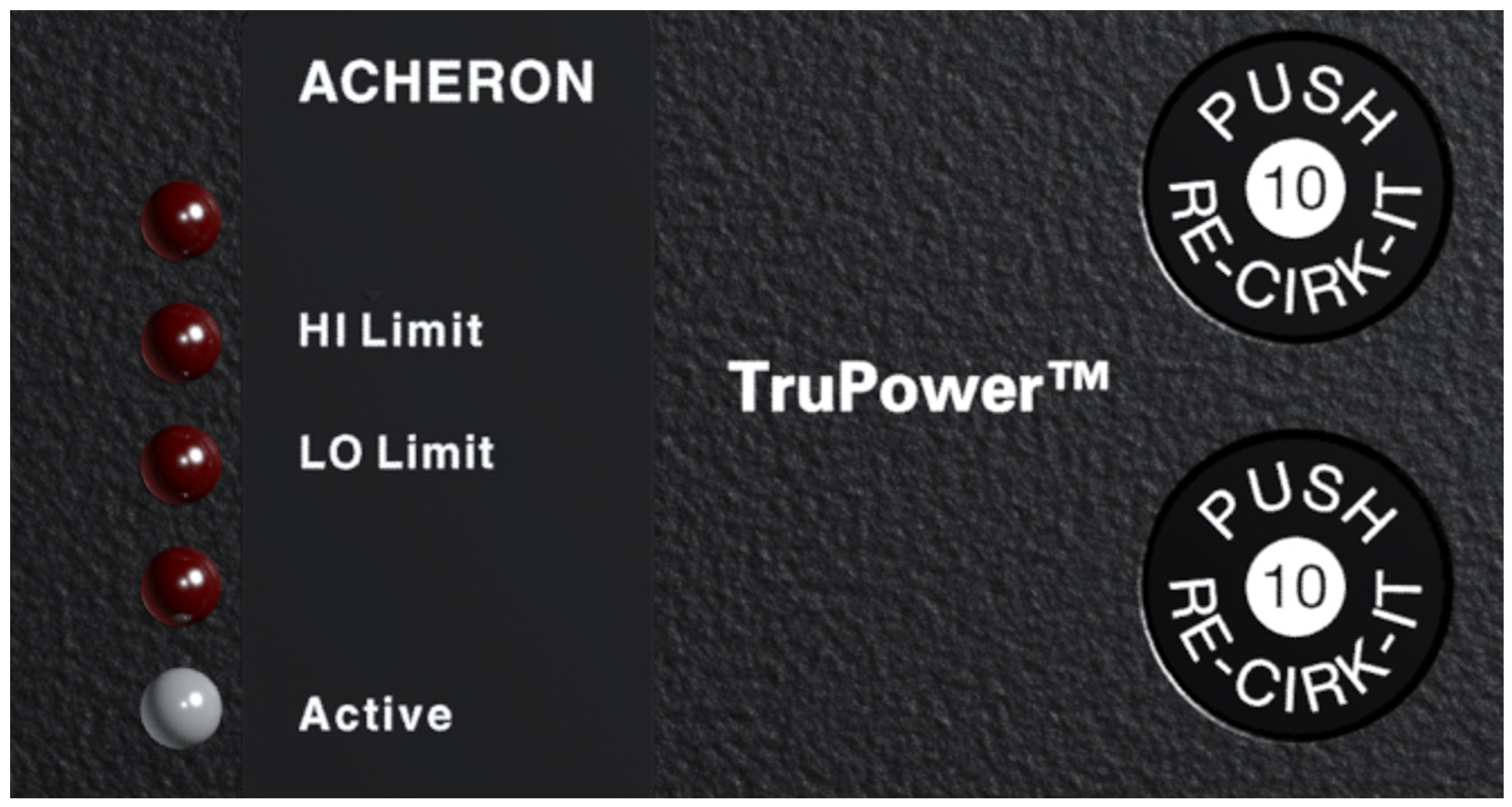 |
Acheron Limit LEDs
In contrast, TruPower limiting anticipates varying loud- speaker impedances by measuring both current and voltage to compute the actual power dissipation in the voice coil.
This improves performance, both before and during limiting, by allowing the driver to produce the maximum SPL across its entire frequency range. TruPower limiting also eliminates power compression at high levels over lengthy periods, which helps regulate voice coil temperatures, thereby extending the life of the driver.
Note
Since TruPower limiting only reduces signal levels to keep voice coil temperatures under a safe margin, signal peaks remain unaffected.
Limiting LEDs
Behavior for the Acheron Limit LEDs is described below:
The low- and high-frequency drivers for the Acheron 80 and Acheron 100 are powered by separate amplifier channels, each with their own limiter. Limiting activity is indicated with a High Limit LED for the high-frequency channel, and a Low Limit LED for the low-frequency channel.
The two low-frequency drivers for the Acheron LF are powered by separate amplifier channels that are routed to a single limiter. When a safe power level is exceeded in either channel, limiting is engaged for both channels and the Low Limit LED lights.
When engaged, the limiters not only protect the drivers but also prevent signal peaks from causing excessive distortion in the amplifier channels, thereby preserving headroom and maintaining smooth frequency responses at high levels.
When levels return to normal, below the limiter thresholds, limiting ceases.
The Acheron performs within its acoustical specifications at normal temperatures when the Limit LEDs are unlit, or if the LEDs are lit for two seconds or less and then turn off for at least one second. If the LEDs remain lit for longer than three seconds, the loudspeaker enters hard limiting where:
Increases to the input level have no effect.
Distortion increases due to clipping and nonlinear driver operation.
The drivers are subjected to excessive heat and excursion, which will compromise their life span and may eventually lead to damage over time.
Caution
The Limit LEDs indicate when a safe, optimum level is exceeded. If the Acheron 80s or Acheron 100s in a system begin to limit before reaching the required SPL, consider adding Acheron LFs to the system. For more information, see Integrating Acheron LF Loudspeakers
Note
Acheron loudspeakers use optical limiters that add no noise and have no effect on the signal when the limiters are not engaged and the Limit LEDs are not lit.
Amplifier Cooling System
The Acheron uses a forced-air cooling system with two fans (one variable-speed, ultra-low-noise primary fan and one reserve fan) to prevent the amplifier module from overheating. The fans draw air in through ducts on the front of the cabinet, over the heat sink, and out the rear of the cabinet. Because dust does not accumulate in the amplifier circuitry, its life span is increased significantly.
 |
Airflow for the Acheron
When the Acheron heat sink temperature is below 42° C, the variable-speed primary fan runs continuously at its slowest speed with an inaudible operating noise. The primary fan increases speed when the heat sink temperature reaches 42° C; the primary reaches full speed at 62° C and is barely audible near the cabinet, even without an audio signal. If the heat sink temperature reaches 74° C, the reserve fan turns on. The reserve fan turns on if:
The primary fan has failed (check status immediately)
High source levels are encountered for extended periods
Dust has accumulated along the cooling path
The reserve fan turns off when the heat sink temperature lowers to 68° C.
Note
In the unlikely event that the reserve fan does not keep the Acheron heat sink temperature below 85° C, the unit automatically shuts down until AC power is removed and reapplied. If the Acheron shuts down again after cooling and re- applying AC power, contact Meyer Sound for repair information.
Dust and the Amplifier Module
Operating the Acheron in dusty environments, or for prolonged, intensive periods, may cause dust to accumulate along its airflow path, thereby preventing normal cooling. Under these circumstances, it may be necessary to periodically remove the air intake foam and use compressed to air to clear the dust from the foam and air ducts.
In addition, if the amplifier gets unusually hot, you should remove the amplifier module and use compressed air to clear any dust from its heat sink.
Caution
Make sure to unplug the AC power from the Acheron before cleaning its amplifier.
To keep the Acheron from getting too hot, allow for proper ventilation, 3–4 inches, behind the loudspeaker.
Integrating Acheron LF Loudspeakers
To meet the SPL and low-frequency headroom requirements of large rooms, the Acheron 100 or Acheron 80 can be daisy-chained with the Acheron LF loudspeaker, creating a system with three low-frequency drivers and one high-frequency driver. Adding an Acheron LF yields approximately a 10 dB boost in the low-frequency range, depending on loading conditions and room acoustics.
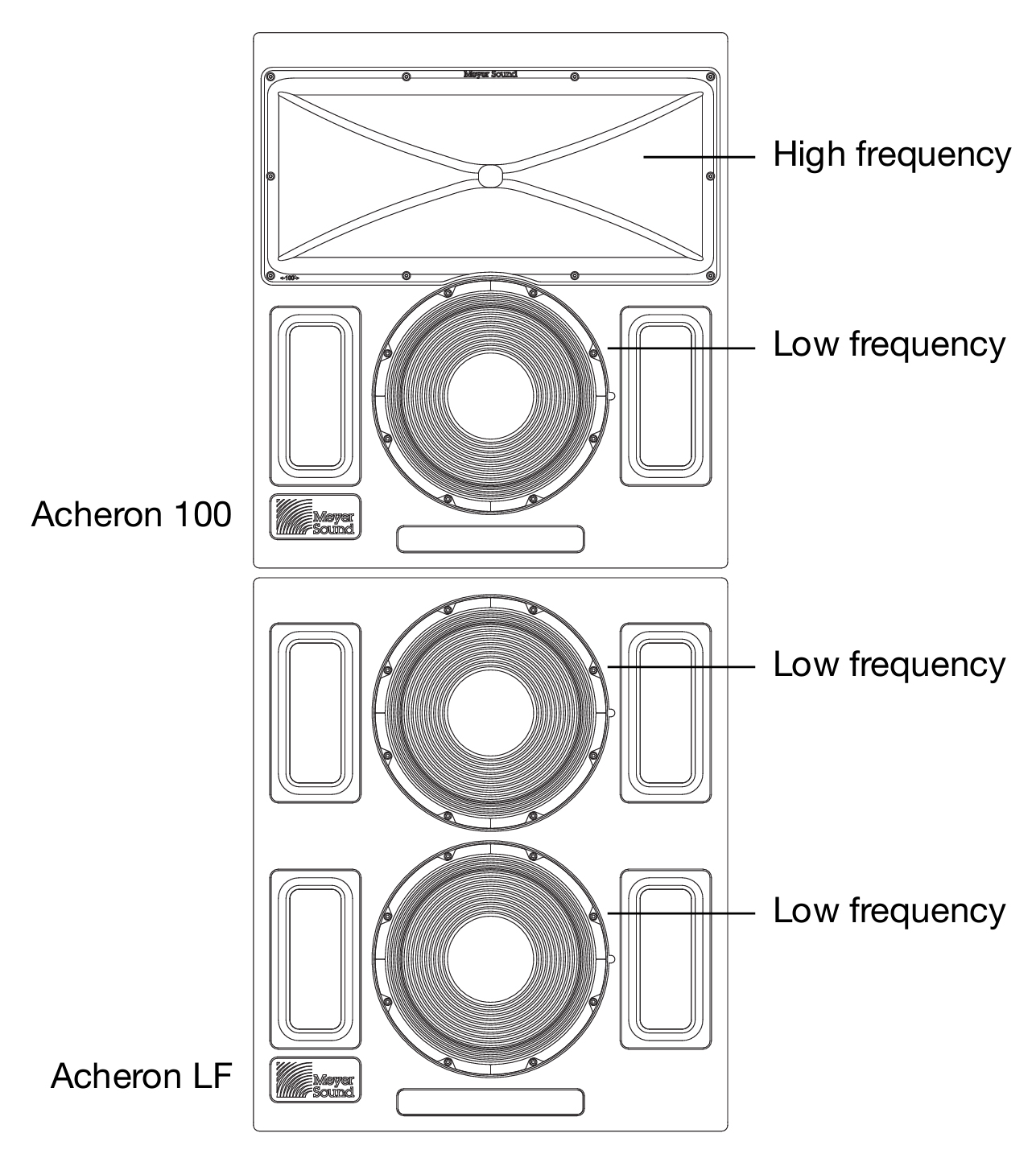 |
Acheron 100 with Acheron LF
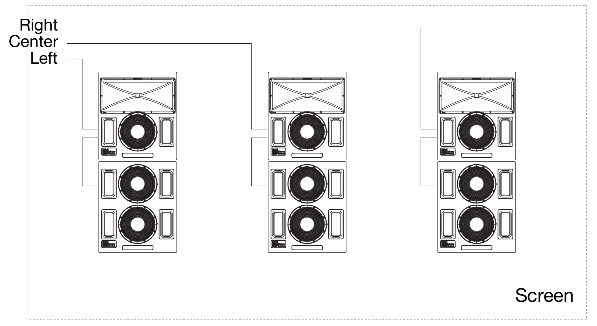 |
Acheron LCR System with Acheron LFs
The Acheron LF has been carefully designed so that its frequency and phase responses complement the Acheron. The Acheron LF has the same low-end frequency response as the Acheron (38 Hz) and rolls off at 320 Hz to avoid any interference in the crossover region of the Acheron.
At 38 Hz to 150 Hz, the low-frequency driver in the Acheron 80 or Acheron 100 and the two low-frequency drivers in the Acheron LF are all active. At 150 Hz, the bottom Acheron LF low-frequency driver rolls off.
At 150 Hz to 300 Hz, two low-frequency drivers are active: one in the Acheron 80 or Acheron 100 and the top Acheron LF driver. At 300 Hz, the top Acheron LF low-frequency driver rolls off.
At 300 Hz to 580 Hz, only the Acheron 80 or Acheron 100 low-frequency driver is active, which enables a smooth crossover to the high-frequency driver.
This unique multi-way, gradated design offers smooth coverage and maximum low-frequency impact with all drivers active at the lowest frequencies and each rolling off, one at a time, via the internal active crossover. This technique eliminates interference between drivers that would otherwise occur at shorter wavelengths, enabling the system to maintain ideal polar, phase, and frequency responses throughout the low and low-mid operating ranges. As a result, the system can deliver the necessary power to completely fill a large theatre.
Achieving a Flat Frequency Response with an Acheron / Acheron LF Stack
When the Acheron and Acheron LF are daisy-chained (using the Loop output connector on the user panel) an approximate boost of 10 dB at 110 Hz results, depending on the loading conditions and room acoustics. To achieve a flat frequency response in this configuration, a single parametric filter with the following characteristics can be applied to the signal:
Filter type | Parametric |
Frequency | 110 Hz |
Bandwidth | 2 (Q = 0.6667) |
Dimensions | –10 dB |
The Acheron LF has been carefully designed so that its frequency and phase responses complement the Acheron. The Acheron LF has the same low-end frequency response
Caution
When daisy-chaining Acherons and Acheron LFs, make sure the audio cables are wired correctly to avoid polarity reversals.
Using Digital Signal Processors and Crossovers with Acheron Systems
ACOUSTICAL
If a digital signal processor is used to drive an Acheron LCR system, the Acherons and Acheron LFs should be driven from the same processor to keep their delay times the same. Otherwise, a phase shift between the loudspeakers may be encountered. In addition, you should verify the delay time between channels: some digital signal processors may incur channel-to-channel delays when the processor is near maximum throughput, which becomes more likely as the number of filters in use by the processor increases.
In no case should a filter higher than the 2nd order be used on source signals. The additional phase shift introduced by these filters deteriorates the impulse response, and the higher roll-off does not improve crossover interaction.
If loudspeakers will be driven directly from a digital signal processor, make sure the signal is sufficient to drive the total load impedance of the connected loudspeakers. For more information, see Loop output connector.
Strategically placed 3/8-inch threaded points on the side corners of the Acheron cabinet allow the unit to be secured to floors with uptilt or downtilt using the optional mounting brackets. The Acheron can also be mounted on top of the Acheron LF loudspeaker, also with uptilt or downtilt, using the optional stacking brackets. Both brackets are available for purchase from Meyer Sound.