Quickfly Rigging
Important Safety Considerations
When installing Meyer Sound loudspeakers and subwoofers, the following precautions should always be observed:
All Meyer Sound products must be used in accordance with local, state, federal, and industry regulations. It is the owner’s and user’s responsibility to evaluate the reliability of any rigging method for their application. Rigging should only be carried out by experienced professionals.
Use mounting and rigging hardware that has been rated to meet or exceed the weight being hung.
Make sure to attach mounting hardware to the building’s structural components (roof truss), and not just to the wall surface.
Make sure bolts and eyebolts are tightened securely. Meyer Sound recommends using Loctite® on all threaded fasteners.
Inspect mounting and rigging hardware regularly. Immediately replace any worn or damaged components.
Rigging Options
The table below summarizes the available rigging options for LINA. For complete information on rigging hardware, including dimensions, weight, configuration, and load ratings, refer to the MG-MINA/LINA/750 Assembly Guide (PN 05.207.101.02).
Model | Weight | Features | Required Quick- Release Pins | Required Shackles |
|---|---|---|---|---|
MG-MINA/LINA/750-LFC multipurpose grid kit (PN 40.207.101.01) | 39 lb (17.7 kg) | With some restrictions, flies up to 16 LINA cabinets at a 5:1 safety factor and BGV C1 with some angle restrictions (additional load ratings are possible—use MAPP to verify load ratings); supports mixed arrays of LINAs and 750-LFCs without transition hardware; accommodates a variety of pickup configurations with four corner and 11 center pickup points; can also be used for groundstacking. | 0.25 in x 0.90 in (black button), PN 134.036, qty 8 included | 5/8-inch or 3/4-inch |
MG-MINA/LINA/750-LFC multipurpose grid kit with GLK (PN 40.207.101.02) | 39 lb (17.7 kg) | With some restrictions, flies up to 16 LINA cabinets at a 5:1 safety factor and BGV C1 with some angle restrictions (additional load ratings are possible—use MAPP to verify load ratings); supports mixed arrays of LINAs and 750-LFCs without transition hardware; accommodates a variety of pickup configurations with four corner and 11 center pickup points; can also be used for groundstacking; includes MG-MINA to 750-LFC Grid Link. | 0.25 in x 0.90 in (black button), PN 134.036, qty 8 included | 5/8-inch or 3/4-inch |
MYA-MINA/LINA Yoke kit (PN 40.207.104.01) | 12.9 lb (5.85 kg) | Suspends arrays of up to three LINA cabinets from a single point and pole-mounts up to two cabinets on top of a 750-LFC (pole-mount adapter not included). The yoke includes two bracketing options: the MPA-2 for attaching to two cabinets, and the MPA-3 for attaching to one or three cabinets. | — | — |
MUB-MINA/LINA U-Bracket kit (PN 40.207.030.01) | 5.8 lb (2.63 kg) | Mounts up to five LINA cabinets for front-fill or under- balcony coverage with up to 20 degrees of tilt. Pole- mounts up to two cabinets (pole-mount adapter not included). | — | — |
PBF-LINA pull-back frame kit (PN 40.271.080.01) | 4 lb (1.8 kg) | Attaches to bottom of LINA arrays (to the bottom cabi- net) and provides pull-back for extreme array downtilt. | 0.25 in x 0.90 in (black button), PN 134.036, qty 2 included | 1/2-inch |
MCF-MINA/LINA caster frame kit (PN 40.207.102.01) | 28 lb (12.7 kg) | Safely transports up to five LINA cabinets, making it easy to assemble and disassemble arrays in blocks of five cabinets. | 0.25 in x 0.90 in (black button), PN 134.036, qty 4 included | — |
LINA GuideALinks
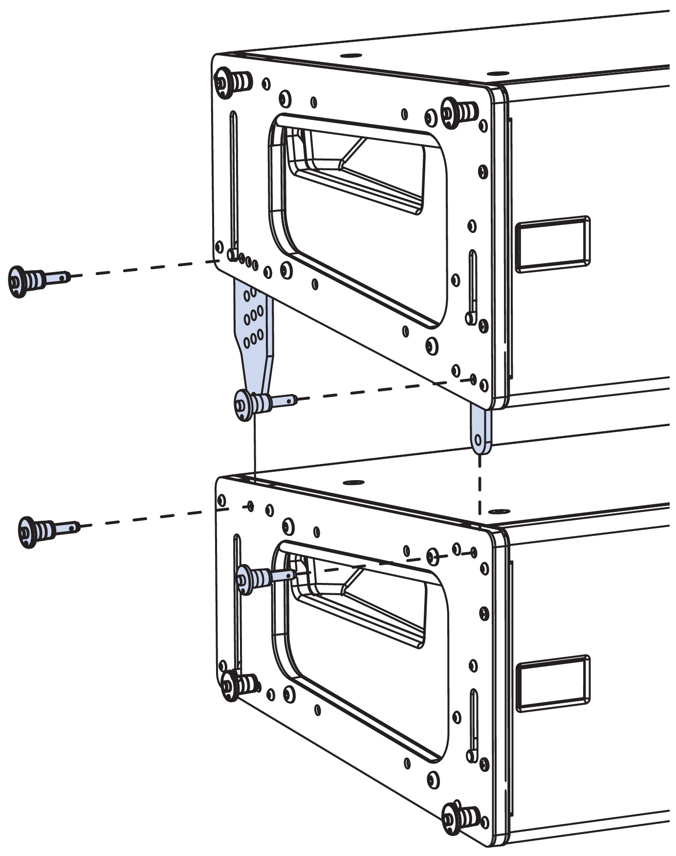
Each LINA loudspeaker is equipped with four captive GuideALinks that link to adjacent units in flown and groundstacked arrays. Located at the bottom corners of the end frames, the GuideALinks extend and retract with knobs and are secured with quick-release pins, as shown in the figure below.
LINA GuideALinks with Quick-Release Pins
Note
When linking LINAs, two quick-release pins are required for each GuideALink: one to secure the position of the link in the top unit, and one to secure the link to the linked bottom unit. Eight (0.25 in x 0.53 in) quick-release pins are included with each LINA.
Caution
Make sure to secure the LINA GuideALinks with the included quick-release pins. GuideALink knobs are for extending and retracting the links and should not be used to support the weight of the loudspeaker (without using the pins) when fully extended.
Front GuideAlinks
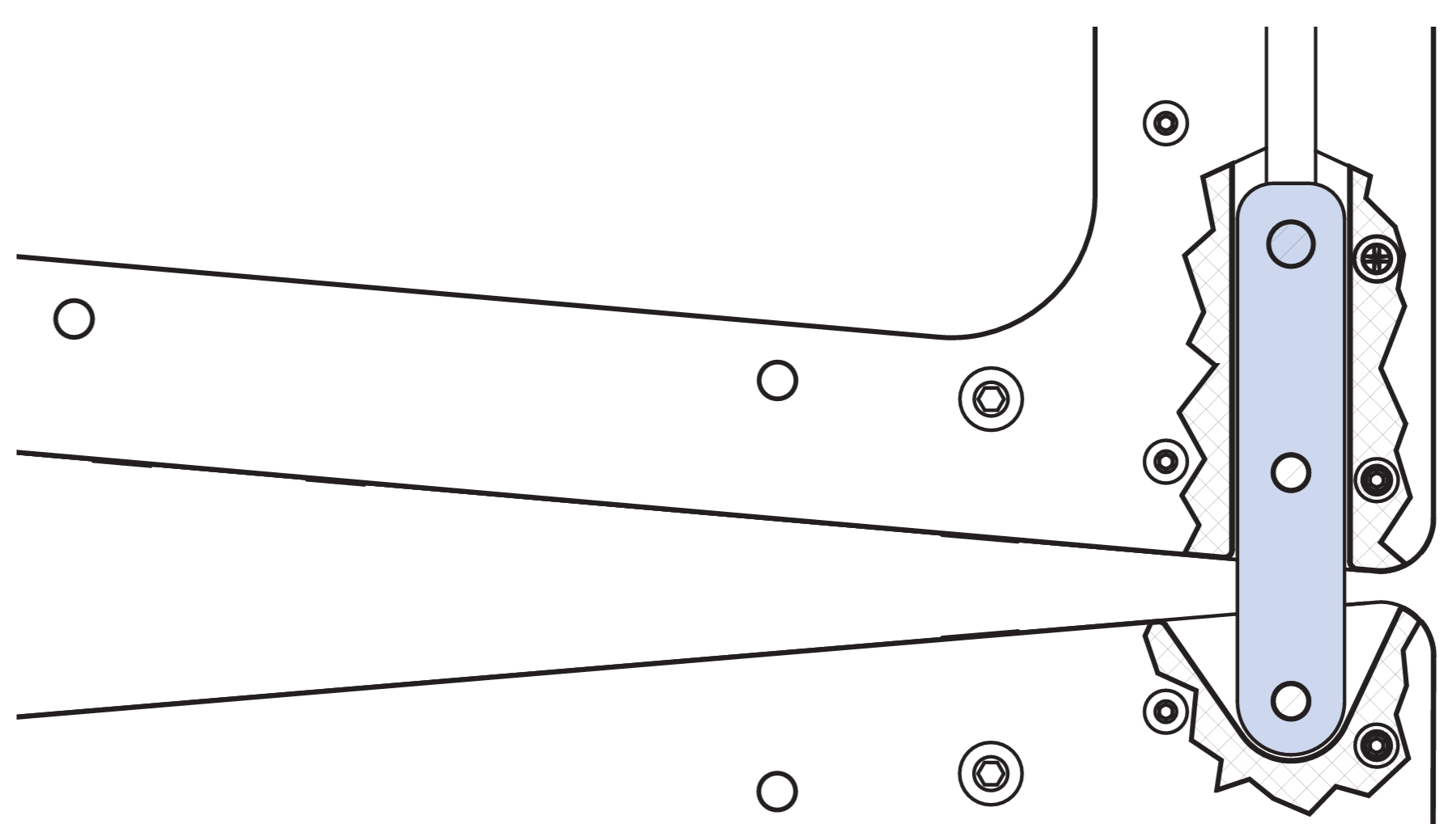
The front GuideALinks, shown in the figure below, act as a pivot point between linked LINAs, with the splay angle between the units determined by the rear GuideALink positions. When stowing front GuideALinks, the knob is positioned at the top of the slot.
Front GuideALinks
Rear GuideALinks
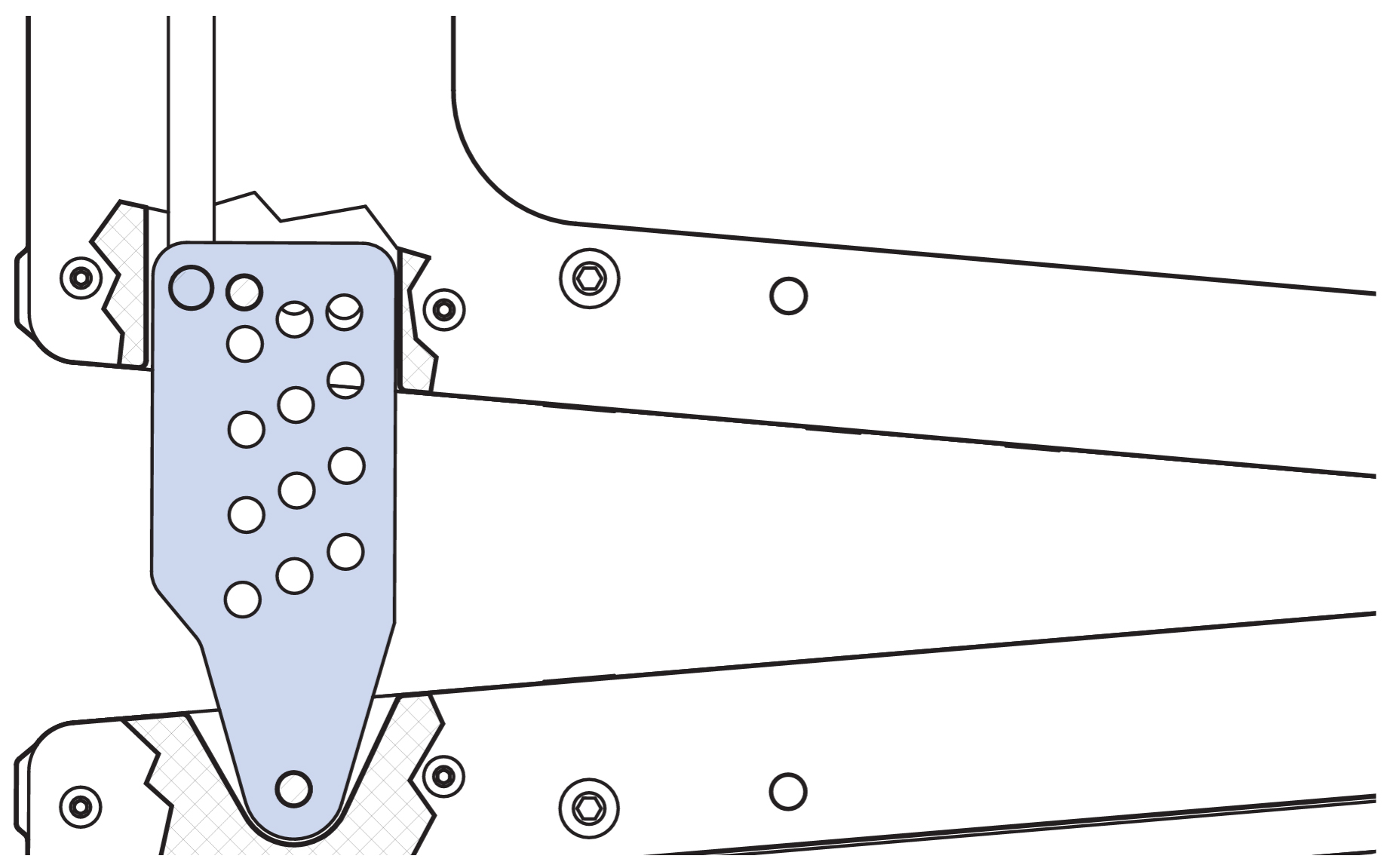
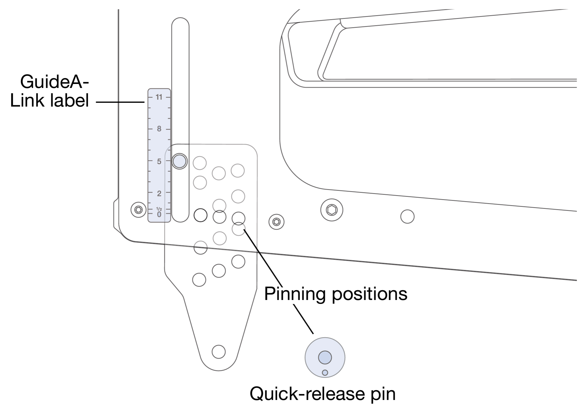
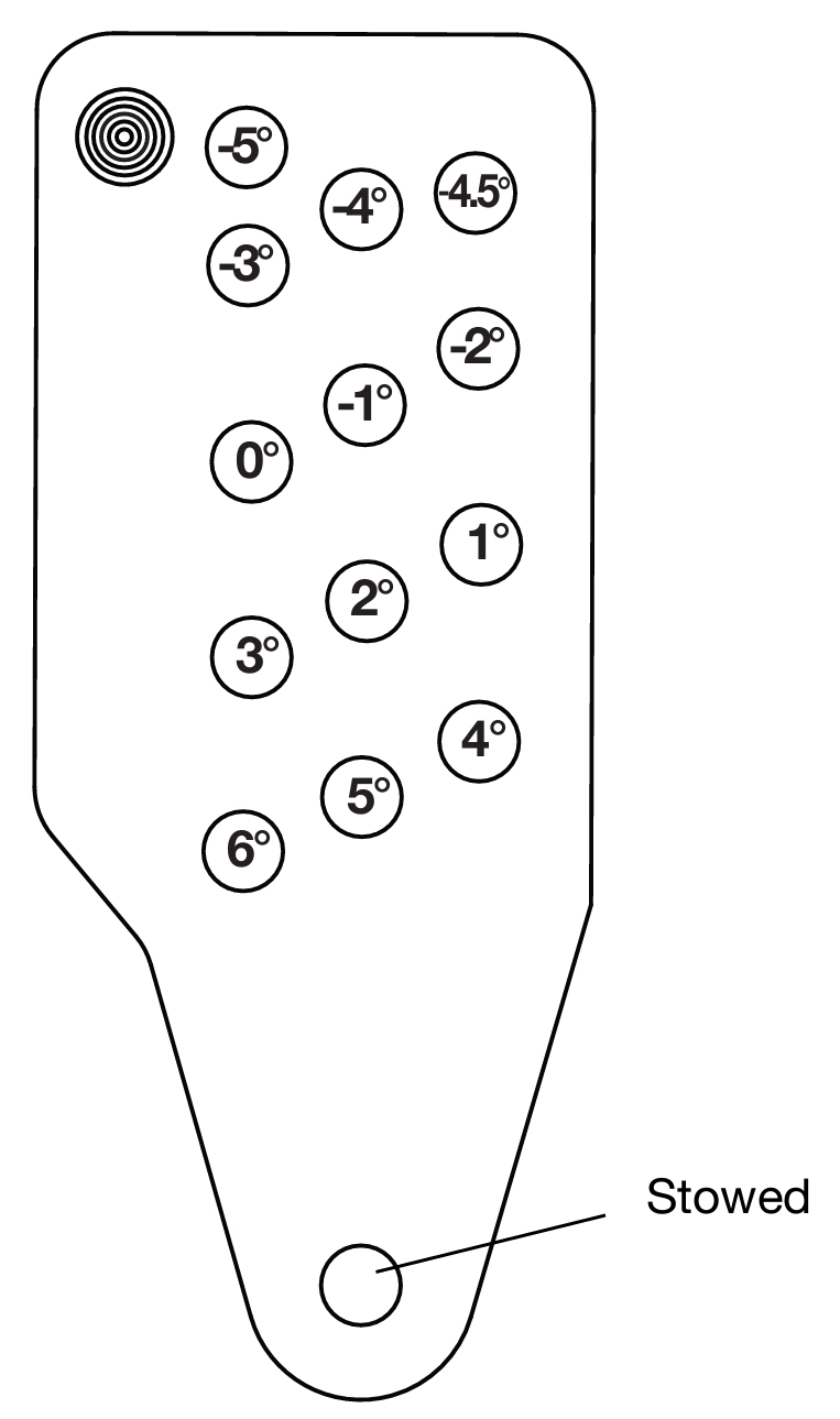
The rear GuideALinks, shown in the first figure below, permit splay angles between linked LINAs at 0.0°, 0.5°, and 1–11° (1° increments). The rear GuideALink includes three rows of holes corresponding to the available splay angles that are secured in one of three pinning positions at the bottom of the unit, as shown in the third figure below.
The label in the lower left corner of the end frame, shown in the second figure below, shows the splay angle for the GuideALink position. With the knob at the bottom, the splay angle is 0°. As the knob is moved up, the angle increases up to 11° (Figure 21). To stow the link, the knob is moved all the way to the top of the slot.
Rear GuideALinks
Rear GuideALink Label and Pinning Positions
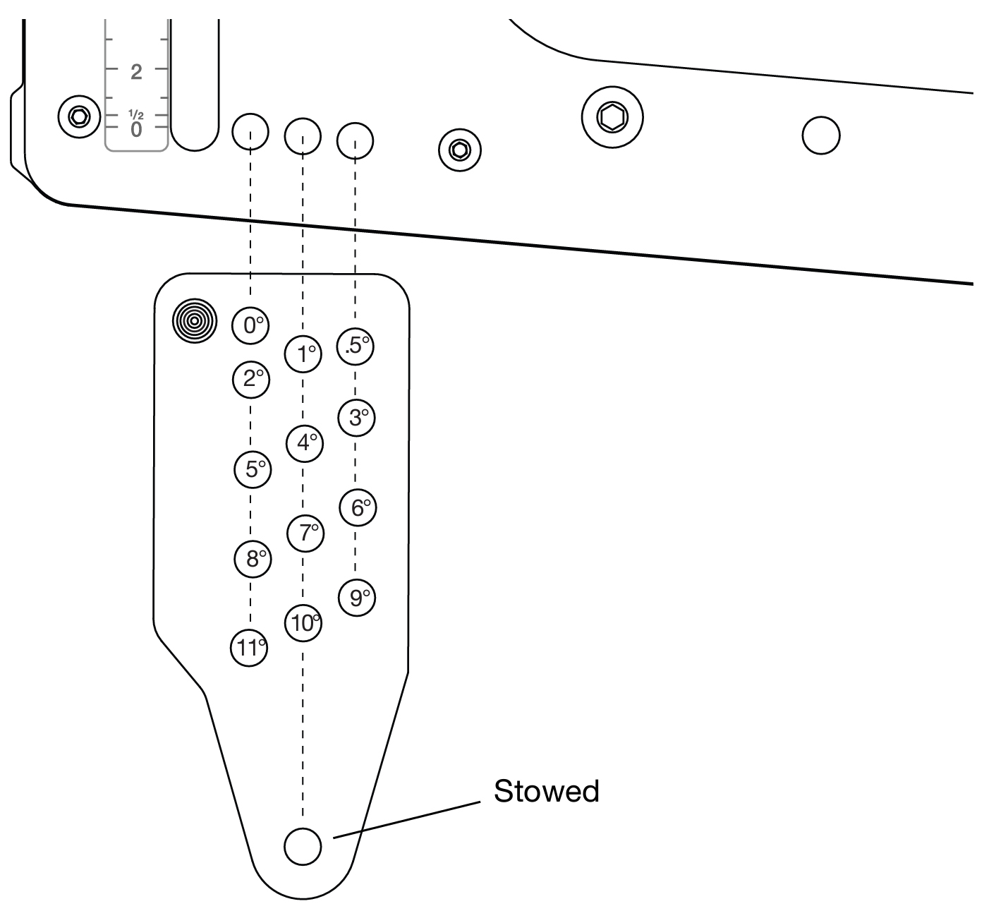
Rear GuideALink, Splay Angles for Linked LINAs
Note
The splay angles listed on the GuideALink label are for relative angles between the linked units. For example, setting the GuideALink to “5” yields a 5° downtilt of the lower unit relative to the upper unit. How the loudspeakers relate to the floor, stage, and seating angles in the venue depends on the orientation of the MG-MINA/LINA/750-LFC grid, the angles of the loudspeakers in the array above them, whether they are flown or ground-stacked, and other factors. Use MAPP system design software to determine the optimum splay angles for loudspeakers and coverage pattern of the array.
To achieve optimal acoustical performance for LINA arrays, use the appropriate number of units and splay angles to meet the coverage requirements of the venue. Utilize MAPP to verify designs and rigging configurations.
MG-MINA/LINA/750-LFC Grid
The MG-MINA/LINA/750-LFC grid, shown in the figure below, flies LINA arrays of up to 16 cabinets at a 5:1 safety ratio. The grid, which can also be used for groundstacking arrays, accommodates a variety of pickup configurations with four side pickup points and 11 center pickup points.
Note
Additional load ratings are possible. Use MAPP to verify load ratings.
For complete information about configuration and load ratings for the MG-MINA/LINA/750-LFC grid, as well as other LINA rigging accessories, refer to the MG-LINA/750-LFC Assembly Guide (PN 05.207.101.02) available at www.meyersound.com.
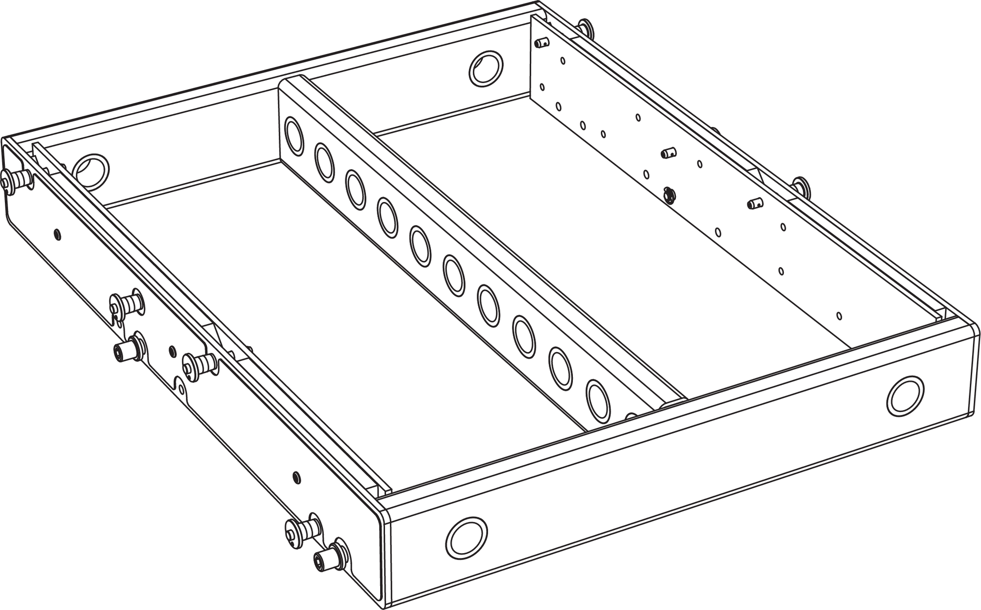
MG-MINA/LINA/750-LFC Grid
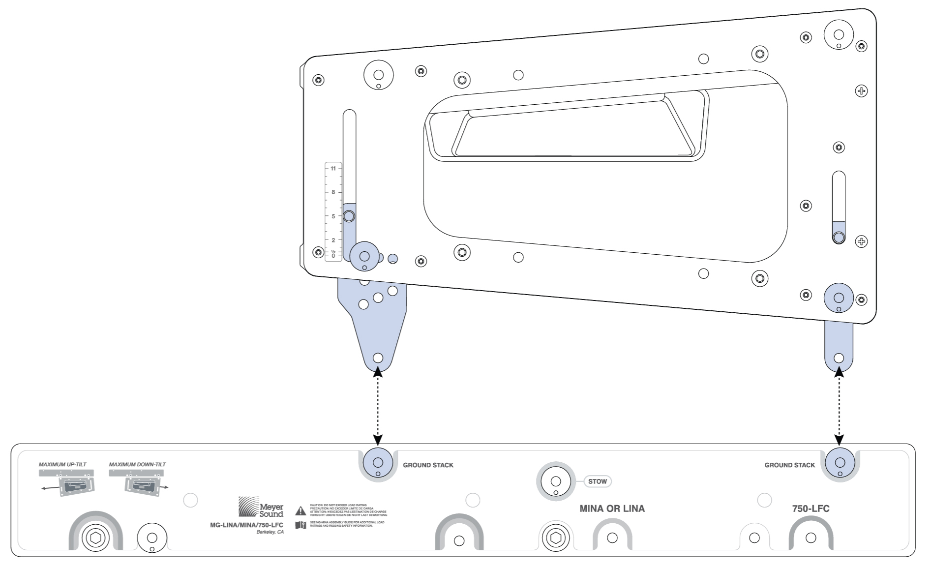
The MG-MINA/LINA/750-LFC grid has four captive links, two per side, that attach to the top LINA in flown arrays. The configuration of the links and orientation of the grid (for either maximum uptilt or maximum downtilt) determine the angle of the attached LINA. The grid links are easily stowed for transport and groundstacked configurations.
The MG-MINA/LINA/750-LFC grid includes eight (0.25 in x 0.90 in) quick-release pins: four for securing the four grid links, and four for securing LINA groundstacks to the top of the grid.
Caution
Always use the quick-release pins included with the MG-MINA/LINA/750-LFC grid to secure its links, as well as to secure groundstacked LINAs to the grid. Do not use the quick-release pins included with LINA in the grid as they are shorter and will not lock in place.
Tip
The MG-MINA/LINA/750-LFC grid can travel installed on top of LINA stacks.
MG-MINA/LINA/750-LFC Grid Orientations for Flown Configurations
The orientation of the MG-MINA/LINA/750-LFC grid determines the maximum downtilt and maximum uptilt for flown arrays.
MG-MINA/LINA/750 Oriented for Maximum Array Downtilt
When the MG-MINA/LINA/750-LFC grid is oriented with the links toward the front of the flown loudspeakers, the grid provides maximum downtilt for the flown array (when tilting the grid). The label on the MG-MINA/LINA/750-LFC shows this configuration as “Maximum Downtilt.”
With the maximum downtilt orientation, the LINA at the top of the array can be attached to the grid at 0° and –5° downtilt, as shown in the figure below.
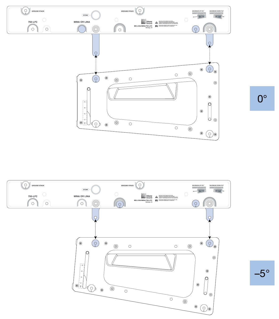 |
MG-MINA/LINA/750-LFC Grid, Maximum Downtilt Orientation, 0° and –5°
Tip
The tilt for the MG-MINA/LINA/750 and the array hung below it can be further tilted by using chain motors, or differing lengths of steel or SpanSets.
MG-MINA/LINA/750-LFC Oriented for Maximum Array Uptilt
When the MG-MINA/LINA/750-LFC grid is oriented with the links toward the rear of the flown loudspeakers, the grid provides maximum uptilt for the flown array (when tilting the grid). The label on the MG-MINA/LINA/750-LFC shows this configuration as “Maximum Uptilt.”
With the maximum uptilt orientation, the LINA at the top of the array can be attached to the grid at –5 and –10° downtilt, as shown in the figure below.
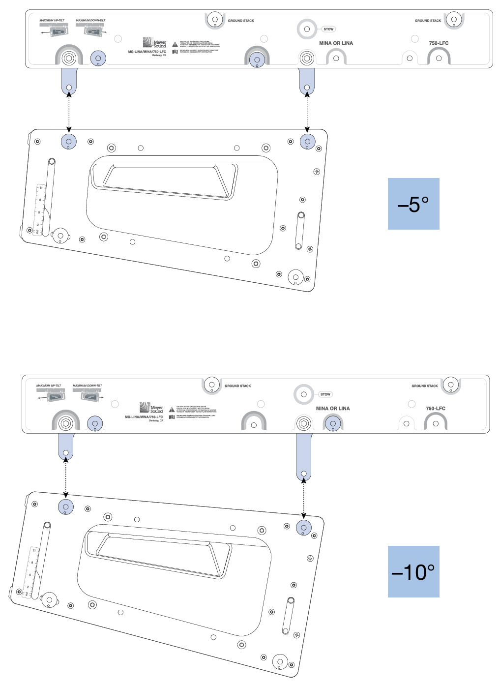
MG-MINA/LINA/750-LFC Grid, Maximum Uptilt Orientation, –5° and -10°
Tip
The tilt for the MG-MINA/LINA/750-LFC and the array hung below it can be further tilted by using chain motors, or differing lengths of steel or SpanSets.
:Use the MAPP System Design Tool’s prediction software to help determine the grid orientation that most appropriately balances the rigging load for a given application. It provides information such as the array COG (center of gravity) marker and front and rear rigging load weights.
MAPP System Design Tool Prediction Examples
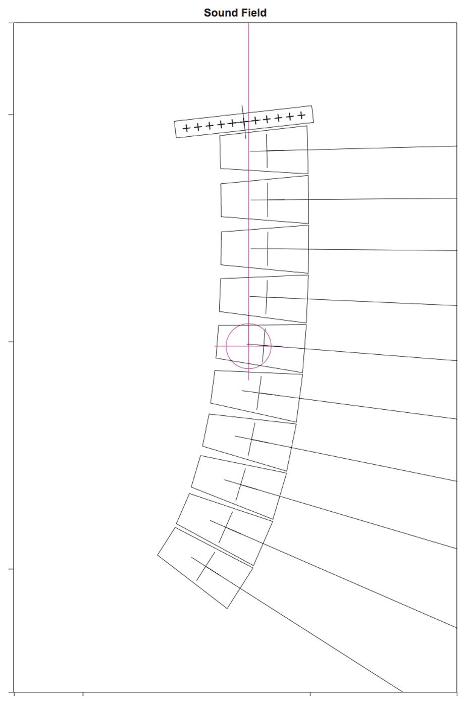
Meyer Sound recommends using the MAPP System Design Tool to determine appropriate grid orientations. For example, the first figure below illustrates the MAPP software display when checking the COG (purple line extending upward) for maximum array uptilt, and the second figure below shows maximum downtilt.
The COG line is also useful when suspending the grid from a single center pickup point. Determine the appropriate point to use by observing which one of the 11 pickup points the COG line intersects.
MAPP COG Maximum Downtilt
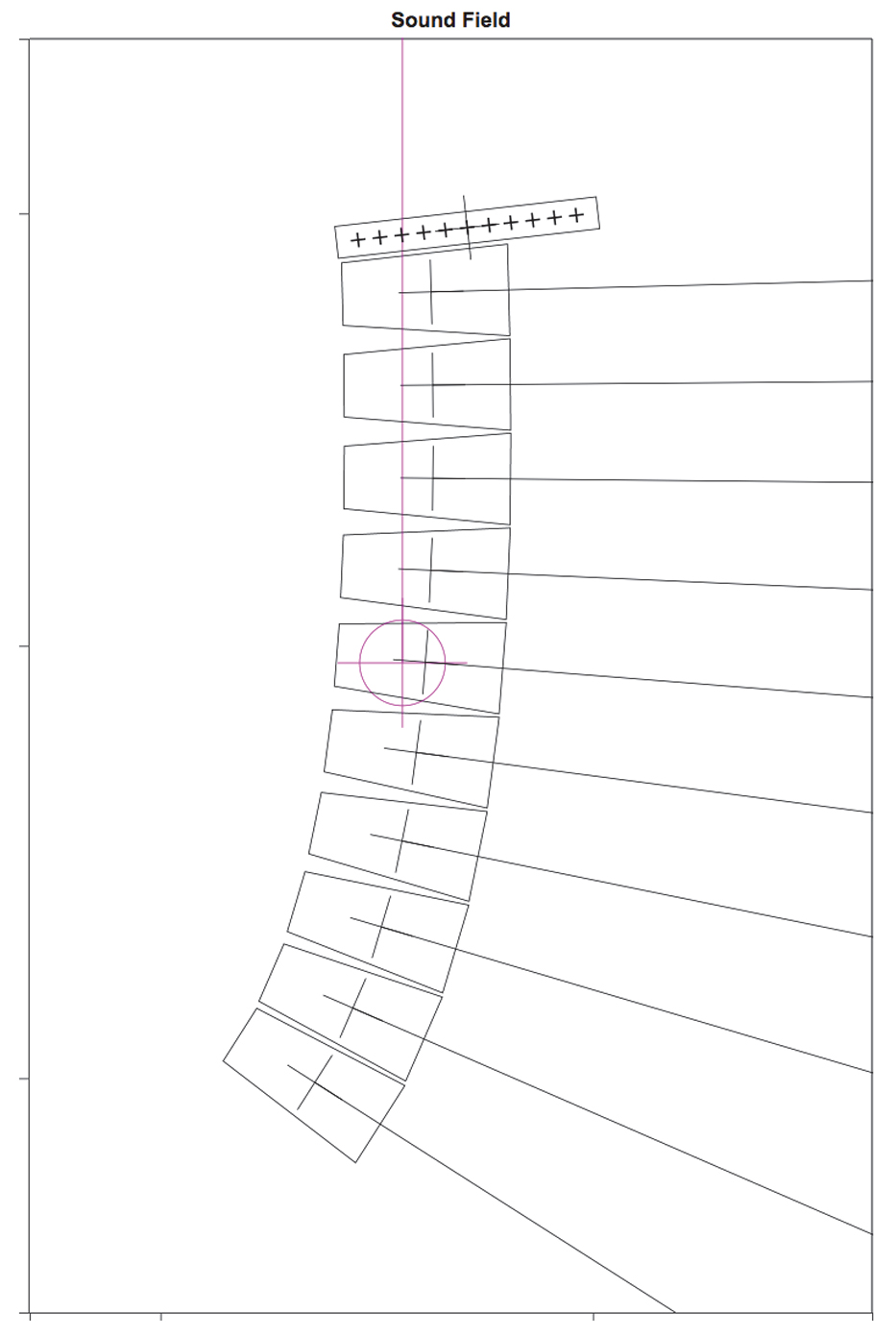
MAPP COG Maximum Downtilt
The MAPP software also provides weight distribution information. Use the grid orientation that has the least difference between the Front and Rear Rigging Loads calculated in the Flown Loudspeaker System Properties window, shown in the figure below.
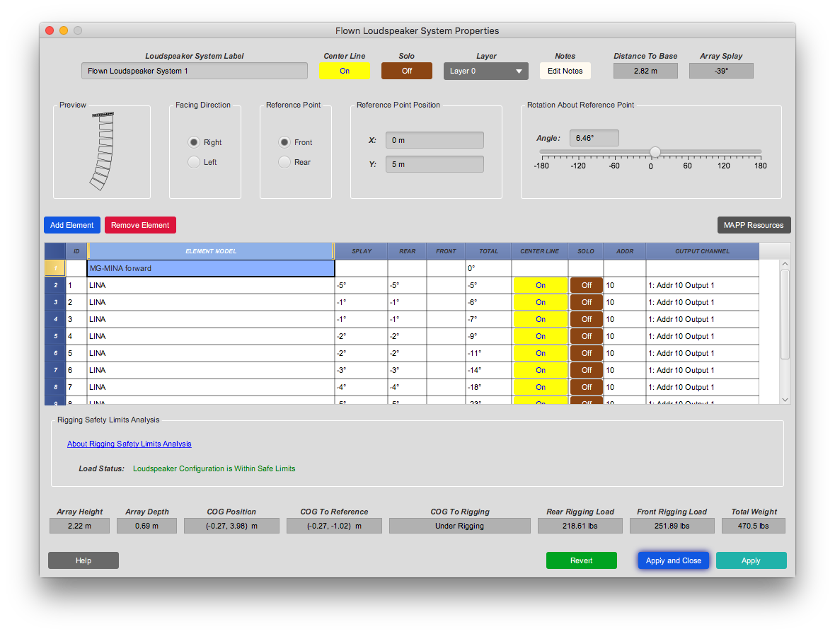
Balanced Rear and Front Rigging Loads.
Groundstacking LINAs with the MG-MINA/LINA/750-LFC
The MG-MINA/LINA/750-LFC grid can also be used for groundstacking up to six LINAs. When used for groundstacking, the grid should be oriented so the center of gravity for the stacked loudspeakers is near the center of the grid. The LINA at the bottom of the stack attaches directly to the grid with its GuideALinks and is secured with the quick-release pins included with the grid, as shown in the figure below. The configuration of the GuideALinks, shown in the second figure below, for the attached LINA determines its tilt, which can be from +6° (uptilt) to –5° (downtilt).
MG-MINA/LINA/750-LFC Grid with Groundstacked LINA
Rear GuideALink, Angles for Groundstacked Units
Caution
To secure groundstacked arrays, particularly in outdoor situations, use tie downs or weights with the grid and/or a safety system on the array.
MYA-MINA/LINA Mounting Yole
The MYA-MINA/LINA mounting yoke flies up to three LINA loudspeakers from a single hanging point using a C-clamp or equivalent, as shown in the figure below, or pole-mounts up to two LINA loudspeakers with a third-party pole-mount adapter (see “Pole-Mounting LINAs with the MYA-MINA/LINA” on page 30). For flown applications, the yoke supports up to 30° of uptilt and severe downtilts of up to 90°. For flying larger arrays, the MG-MINA/LINA/750-LFC grid is recommended; for smaller profile applications, the MUB-MINA/LINA U-bracket is recommended.
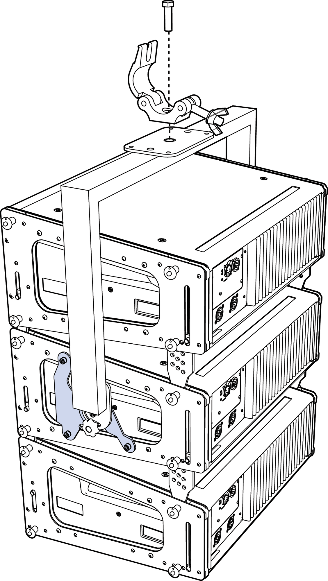
MYA-MINA/LINA with MPA-3 Adapter, Three LINAs, and third-party clamp
Caution
The MYA-MINA/LINA’s mounting bracket at the top of the yoke has one 1/2-inch center hole that is rated for flown applications. The smaller two center holes and four corner holes should only be used for attaching to pole-mount adapters
Note
For complete information about configuration and load ratings for the MYA- image6.pngMINA/LINA, as well as for other rigging accessories, refer to the MG-MINA/LINA/750-LFC Assembly Guide (PN 05.207.101.02).
MYA-MINA/LINA Bracket Options
The yoke includes two bracketing options: the MPA-2 for attaching to two cabinets, and the MPA-3 for attaching to one or three cabinets. The bracket options allow the yoke to attach near the center of gravity for the loudspeakers. The brackets bolt directly to the LINA end frames with the M6 bolts and washers included with the yoke kit. For attaching to the yoke, the brackets include a center/pivot hole and three pinning holes to yield a wide range of uptilt and downtilt angles for the loudspeakers.
MPA-2 Bracket
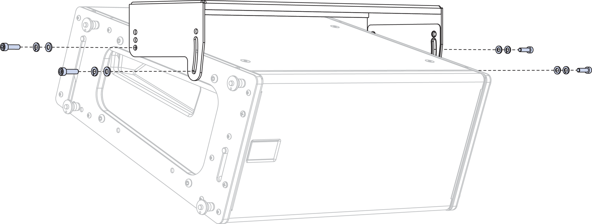
When suspending two LINA cabinets with the MYA-MINA/LINA mounting yoke, use the MPA-2 bracket and attach it to the bottom cabinet, as shown in the figure below.
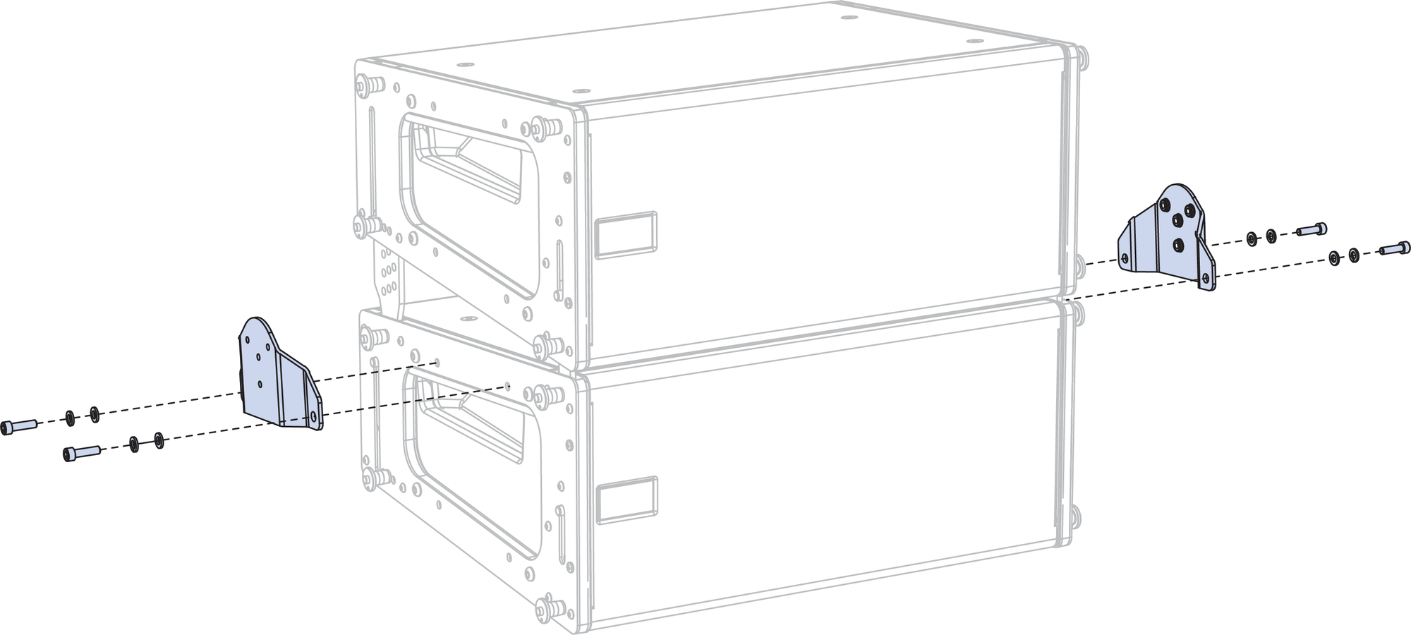
MPA-2 bracket
MPA-3 Bracket
When suspending one or three LINA cabinets with the MYA-MINA/LINA mounting yoke, use the MPA-3 bracket shown in the first figure below. When suspending three cabinets, attach the bracket to the center cabinet, as shown in the second figure below.
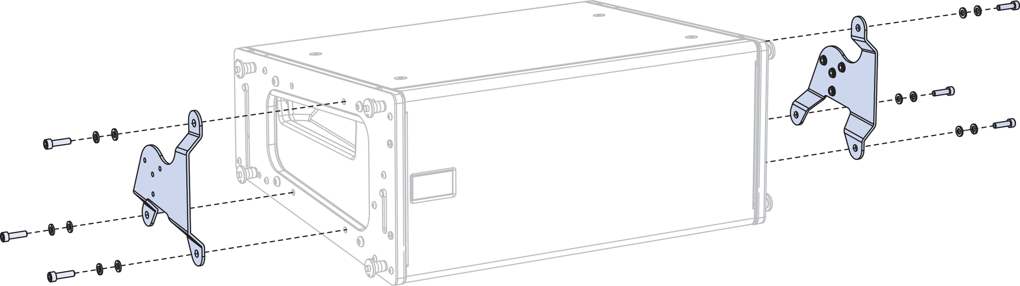
MPA-3 bracket
 |
Flown MYA-MINA/LINA with MPA-3 bracket and Three LINAs
Pole-Mounting LINAs with the MYA-MINA/LINA
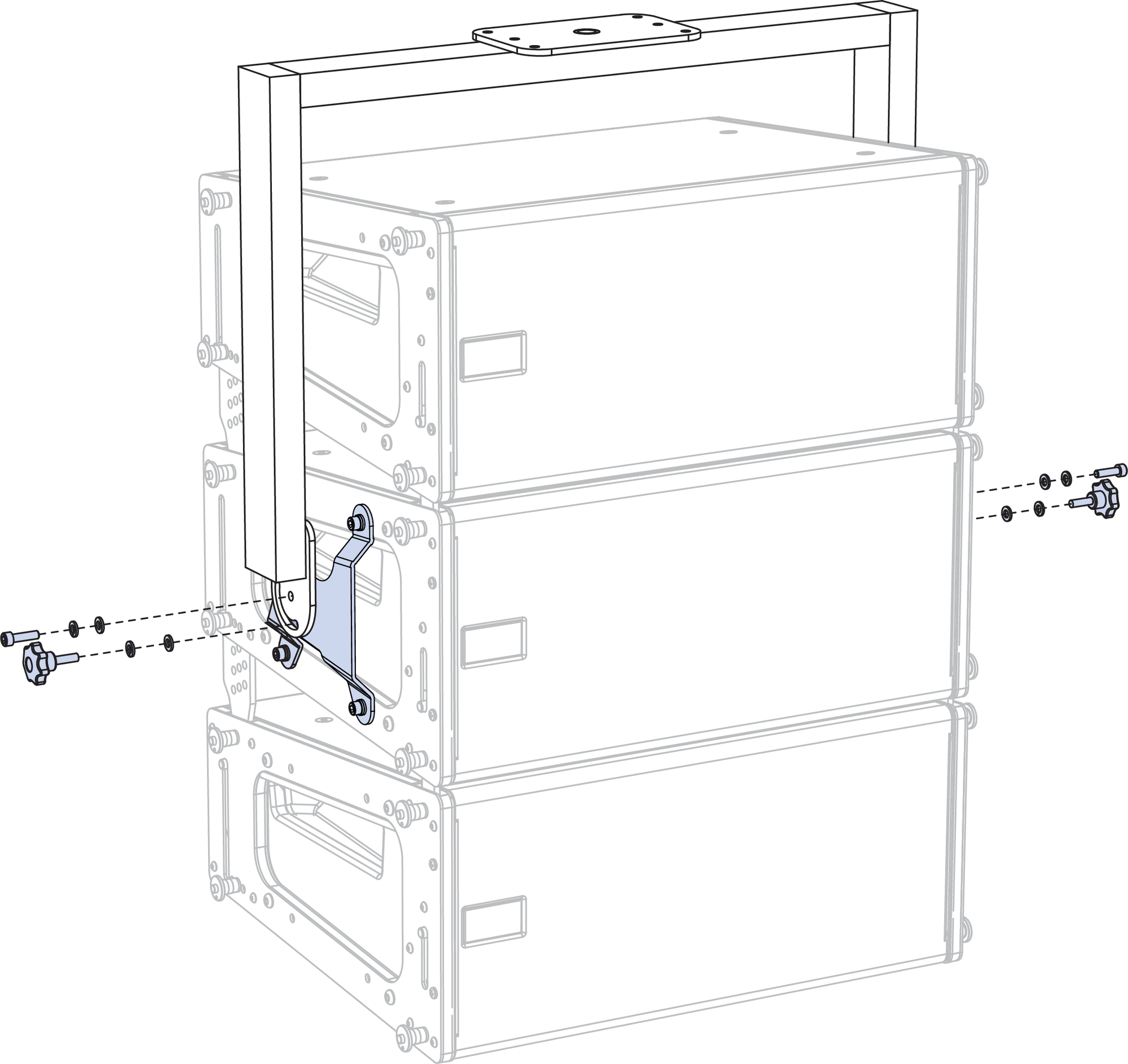
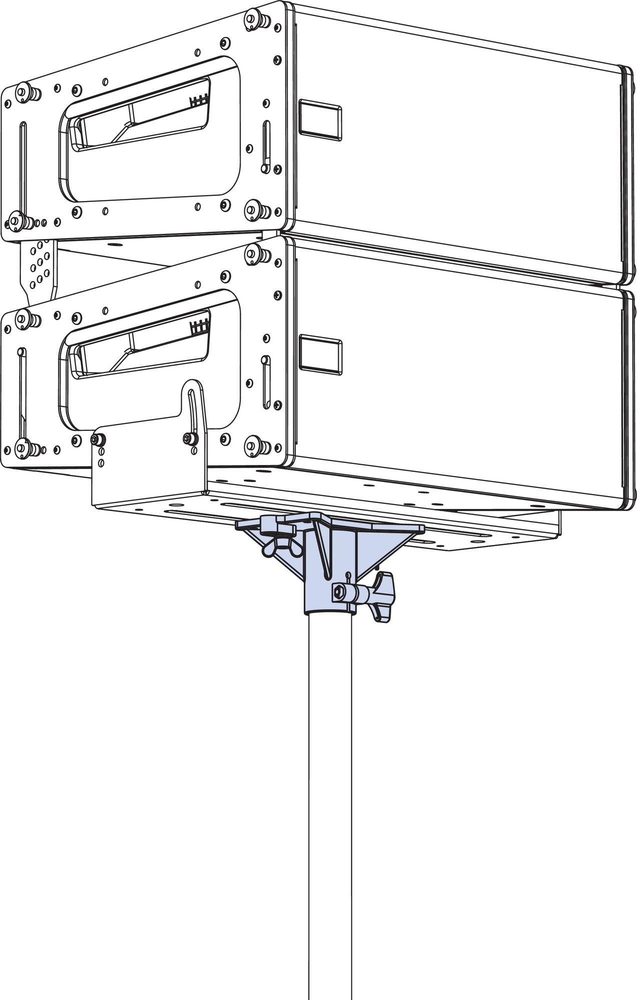
Up to two LINA loudspeakers can be pole-mounted with the MYA-MINA/LINA mounting yoke. For pole-mounting two LINA loudspeakers, use the MPA-2 bracket, shown in the figure below. For pole-mount applications, the yoke supports up to 30° of downtilt and severe uptilts of up to 90°. When pole-mounting LINAs with the yoke, the optional 35 mm pole stand adapter is required (PN 40.010.971.01).
 |
Pole-Mounted MYA-MINA/LINA with MPA-2 bracket and Two LINA loudspeakers with optional 35 mm pole stand adapter
Caution
When mounting the MYA-MINA/LINA on a pole, make sure the pole and pole-mount adapter have been rated to support the full weight of the yoke and loudspeakers. Observe all safety precautions specified by the pole and pole-mount adapter manufacturer.
MUB-MINA/LINA U-Bracket
The MUB-MINA/LINA U-bracket was primarily designed for aiming a single LINA loudspeaker in floor- and ceiling-mount configurations (F[→ _bookmark60]igure 35). However, the U-bracket is strong enough to fly arrays of up to five cabinets, or stack up to two cabinets in floor- and pole-mount configurations. With the
U-bracket, up to two LINA loudspeakers can also be flown from trusses using C-clamps or the equivalent. For flying and groundstacking larger arrays, the MG-MINA/LINA/750-LFC grid is recommended; for applications requiring continuous adjustability or greater downtilt and uptilt angles, the MYA-MINA/LINA mounting yoke is recommended.
Note
For complete information about configuration and load ratings for the MUB-MINA/LINA, as well as for other rigging accessories, refer to the MG-MINA/LINA/750-LFC Assembly Guide (PN 05.207.101.02).
Ceiling-Mounted MUB-MINA/LINA with One LINA
The MUB-MINA/LINA U-bracket’s mounting holes and mounting slot provide maximum flexibility for the loudspeaker’s uptilt and downtilt. For flown applications, the MUB-MINA/LINA can be oriented for either maximum downtilt (with the slot near the front of the loudspeakers) or maximum uptilt (with the slot near the rear of the loudspeakers).
For a single flown cabinet, the MUB-MINA/LINA supports continuous angles of 0° to –20° in the maximum downtilt orientation, and angles of +10° to –10° in the maximum uptilt orientation.
For multiple flown cabinets, the MUB-MINA/LINA supports fixed angles of +10°, 0°, –5°, –10° and –20° (with either orientation).
Note
For multiple flown cabinets, the MUB-MINA/LINA slot is not recommended for variable adjustments, because the angle could change over time due to the weight of the cabinets.
For illustrations showing which MUB-MINA/LINA mounting holes and slot image6.pngconfigurations to use to achieve specific angles, refer to the MG-MINA/LINA/750-LFC Assembly Guide (PN 05.207.101.02).
Floor- and Pole-Mounting LINAs with the MUB-MINA/LINA
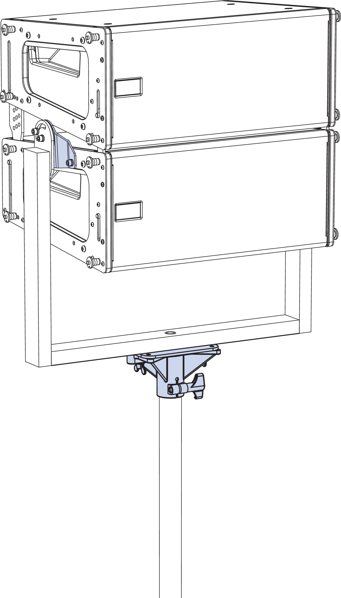
Up to two LINA loudspeakers can be floor or pole-mounted with the MUB-MINA/LINA U-bracket, shown in the figure below. When pole-mounting LINAs with the U-bracket, the optional 35 mm pole stand adapter is required (PN 40.010.971.01). For floor- and pole-mounted applications, the MUB-MINA/LINA can be oriented for either maximum downtilt (with the slot near the rear of the loudspeakers) or maximum uptilt (with the slot near the front of the loudspeakers).
For a single floor- or pole-mounted cabinet, the
MUB-MINA/LINA supports continuous angles from +10 to –10° in the maximum downtilt orientation, and angles of 0 to +20° in the maximum uptilt orientation.
For multiple floor- or pole-mounted cabinets, the
MUB-MINA/LINA supports fixed angles of 0, +5, and +10° (with either orientation).
Pole-Mounted MUB-MINA/LINA/750 with Two LINA loudspeakers using the 35 mm pole stand adapter
Caution
When mounting the MUB-MINA/LINA on a pole, make sure the pole and pole stand adapter have been rated to support the full weight of the U-bracket and loudspeakers. Observe all safety precautions specified by the pole and pole-mount adapter manufacturer.
Note
For illustrations showing which MUB-MINA/LINA mounting holes and slot configurations to use to achieve specific angles, refer to the MG-MINA/LINA/750-LFC Assembly Guide (PN 05.207.101.02).
PBF-LINA Pullback Frame
For applications requiring extreme array downtilt that is not possible with adjustments to the motors attached to the grid, the optional PBF-LINA pull-back frame can be attached to the bottom cabinet in LINA arrays and pulled by a separate motor. The pull-back frame is secured to the bottom cabinet with the quick-release pins (0.25 in x 0.53 in, black button, PN 134.039) included with LINA. The PBF-LINA pull-back frame requires 1/2-inch shackles for its two pickup points.
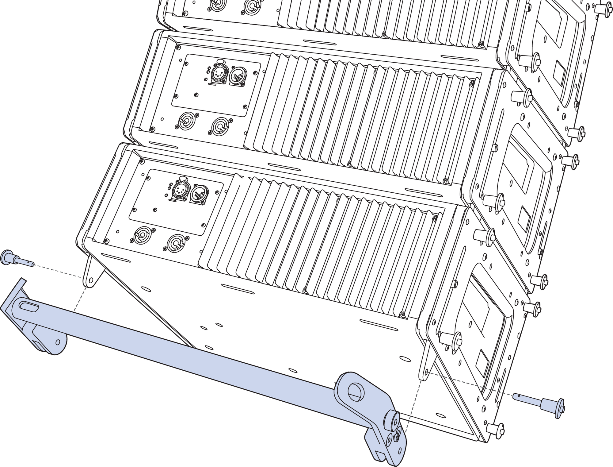
PBF-LINA Pull-Back Frame Attached to Bottom LINA, Exploded View
Note
For complete information about the PBF-LINA, as well as for other rigging accessories, refer to the MG-MINA/LINA/750-LFC Assembly Guide (PN 05.207.101.02).
MVP Motor Vee Plate
The optional MVP motor Vee plate fine-tunes the horizontal aim of LINA and 750-LFC arrays ±16 degrees. The bottom of the Vee plate attaches to the MG-MINA/LINA/750-LFC grid’s front-most or rear-most point on the center pickup bar, while the top corners of the Vee plate attach to two motors, which, when adjusted, affect the horizontal rotation of the grid. The Vee plate’s attachment points require 3/4- inch or 7/8-inch shackles. The Vee plate should always be placed on the grid side (front or rear) with the lower load value.
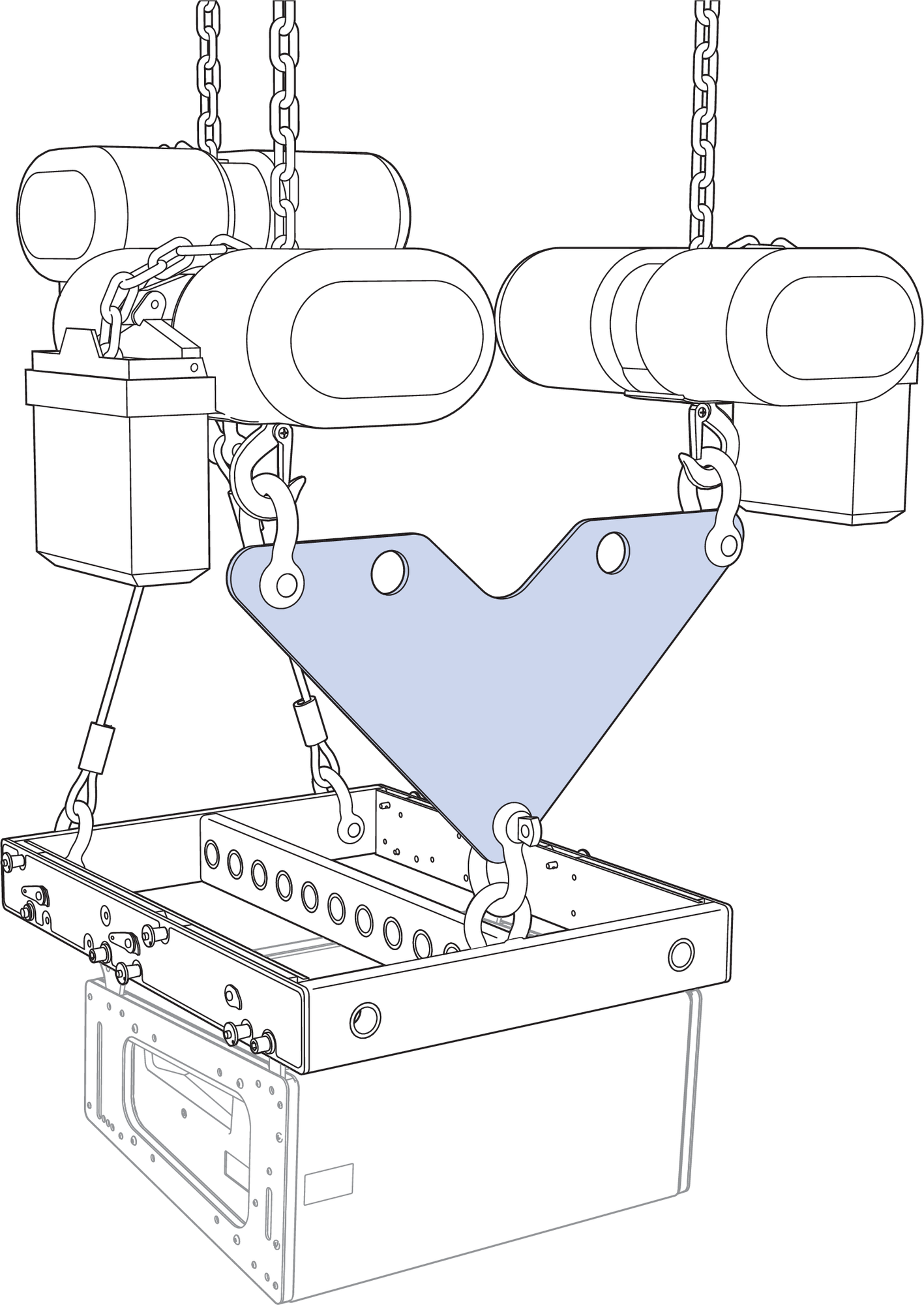
MVP Motor Vee Plate Attached to MG-MINA/LINA/750-LFC Grid
Caution
Always use properly rated rigging hardware. The MVP motor Vee plate requires 3/4-inch or 7/8-inch shackles for its attachment points.
Use MAPP to determine the weight distribution between the front and rear of the grid. Use the point(s) carrying the lesser weight to attach the MVP motor Vee plate.
Note
The MVP motor Vee plate is compatible with any Meyer Sound grid with front and rear center pickup points.
MCF-MINA/LINA Caster Frame
The MCF-MINA/LINA caster frame, shown in the first figure below, safely supports up to five LINAs, as shown in the second figure below, for transport and groundstacking, making it easy to assemble or disassemble arrays. The caster frame’s sturdy construction allows it be conveniently moved with forklifts.
Note
For complete information on the MCF-MINA/LINA, as well as for other rigging accessories, refer to the MG-MINA/LINA/750-LFC Assembly Guide (PN 05.207.101.02).
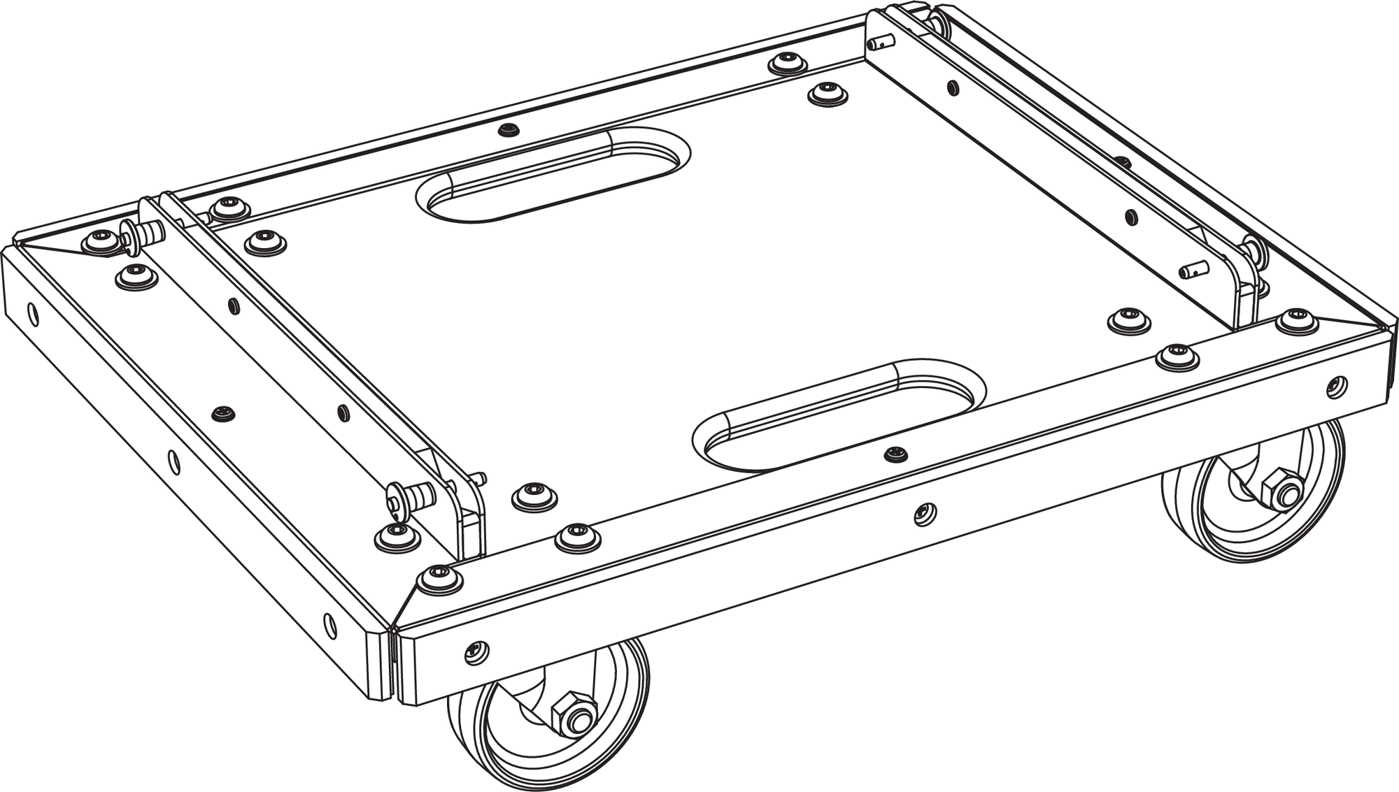
MCF-MINA/LINA Caster Frame
The LINA at the bottom of the stack attaches securely to the caster frame with its GuideALinks and is secured with the four (1/4 by 0.90-inch) quick-release pins included with the caster frame. The configuration of the GuideALinks for the attached LINA determines its tilt, which can be from +6° (uptilt) to –5° (downtilt).
Caution
Always use the quick-release pins included with the MCF-MINA/LINA caster frame to secure groundstacked LINAs to the grid. Do not use the quick-release pins included with LINA in the frame as they are shorter and will not lock in place.
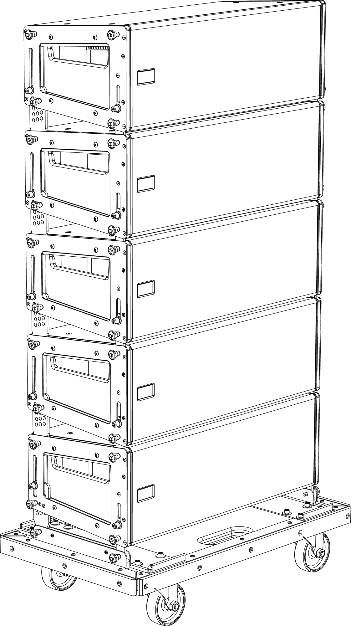
MCF-MINA/LINA Caster Frame with LINA Stack
Tip
The MG-MINA/LINA/750-LFC grid can travel installed on top of LINA stacks.
Durable nylon covers, sized for stacks of 3, 4, and 5 units, are available to ensure the LINA is completely road ready.
Safety Guidelines for the MCF-MINA/LINA Caster Frame
Do not stack more than five LINAs.
Avoid moving stacks in the front-to-back direction of the LINAs (the long side); always move stacks sideways to avoid tipping, as shown in the figure below.
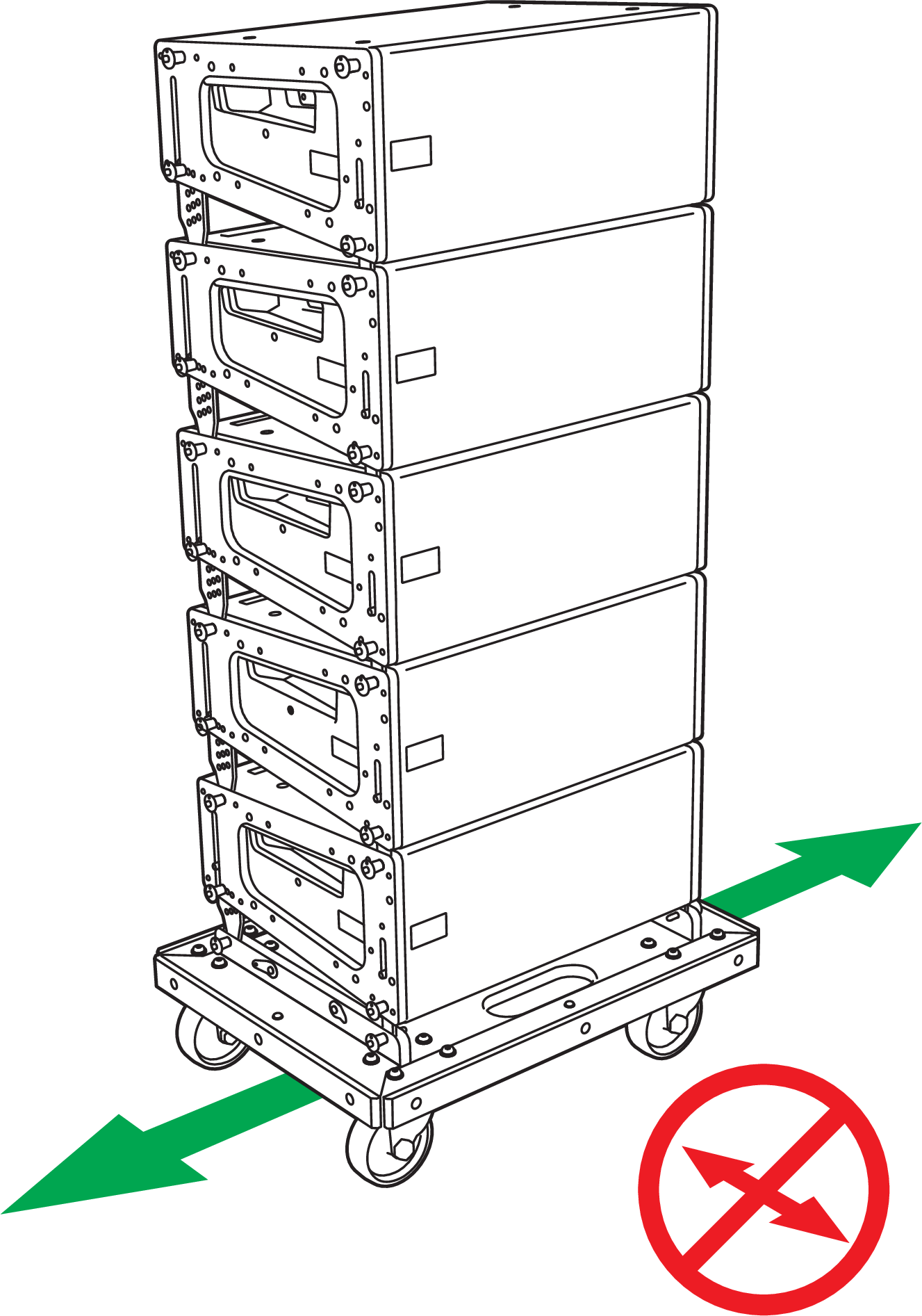
Avoid Moving Stacks in Front-to-Back Direction
When transporting a non-curved LINA stack with 0° splay angles, configure the rear GuideALinks for the bottom LINA so it is attached to the caster frame at 0° (using the 5° hole in the LINA GuideALinks).
When transporting a curved LINA stack with wide splay angles, configure the rear GuideALinks for the bottom LINA so it is attached to the caster frame at –5° (using the 0° hole in the LINA GuideALinks), to compensate for the stack’s center of gravity.
When groundstacking LINAs with the caster frame, make sure that all four caster wheels are blocked to prevent the stack from rolling away.