HMS Loudspeakers
Single Channel Input Connectors (HMS-5, HMS-10, and HMS-12)
The HMS-5, HMS-10, and HMS-12 loudspeakers receive DC power and balanced audio from a single Phoenix 5-pin male Input connector. The connector includes two pins for DC power (positive and negative) and three pins for balanced audio (positive, negative, and shield). The pins are clearly labeled on the HMS user panel. To function properly, the HMS-5, HMS-10, and HMS-12 require an MPS-488HP IntelligentDC power supply (one channel output per loudspeaker). The MPS-488HP can power up to eight single-channel HMS loudspeakers.
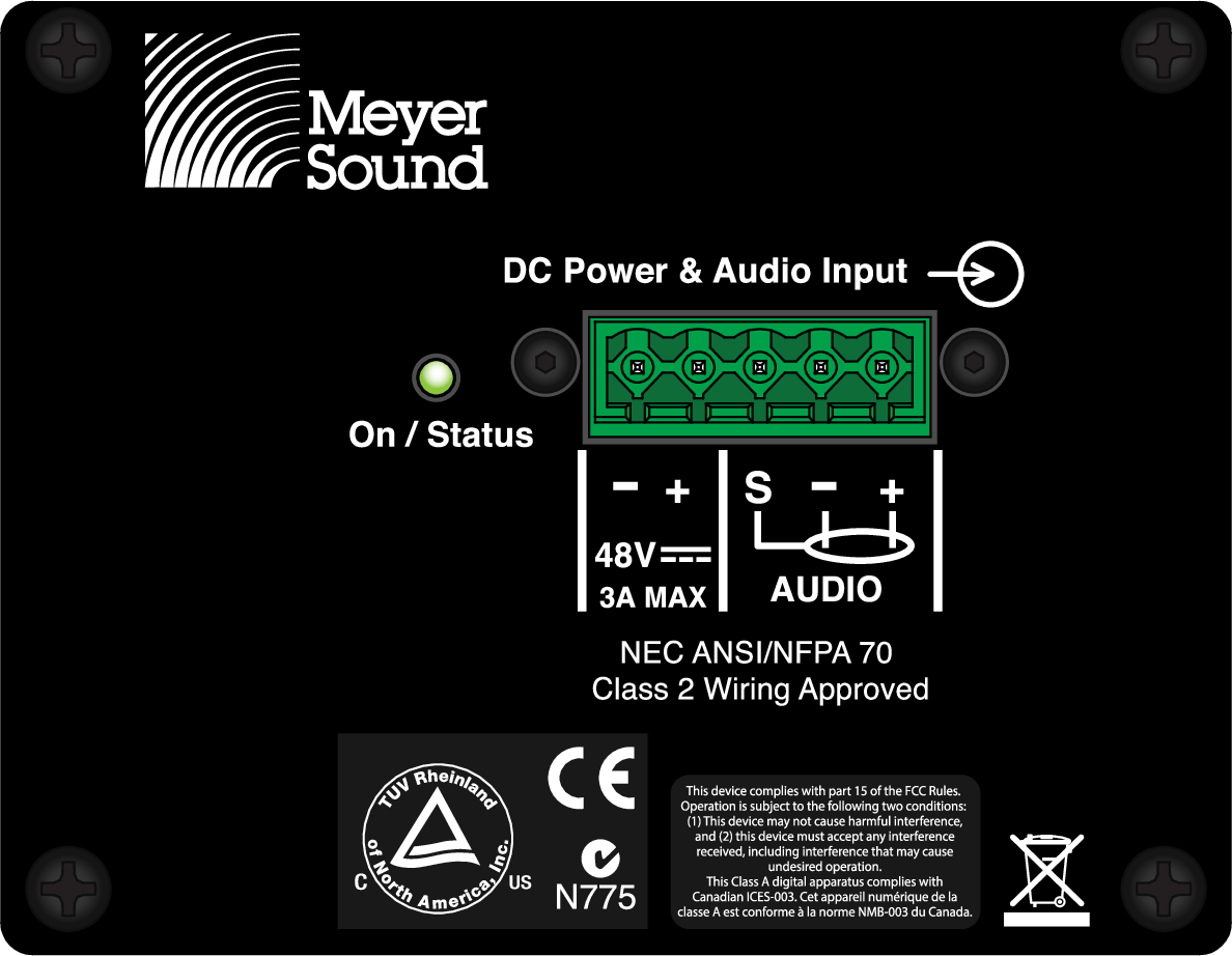 |
Single-Channel Input Connector (HMS-5, HMS-10, and HMS-12)
Single-channel HMS loudspeakers ship with one Phoenix 5-pin female cable mount connector for assembling loudspeaker cables. A single composite cable (such as Belden 1502 or equivalent) can be used to route DC power and balanced audio to the HMS loudspeaker. For more information, see Belden 1502 Cable (or Equivalent) and Assembling Loudspeaker Cables.
Caution
When wiring HMS loudspeaker cables, it is extremely important that each pin be wired correctly. Make sure the 48 V DC from the external power supply is wired directly (and only) to the 48 V DC pins on the loudspeaker connector, and that the polarity is observed (negative to negative, positive to positive) to avoid damage to the loudspeaker. In addition, make sure that audio pins are wired correctly; polarity reversals for audio signals affect system performance.
Dual-Channel Input Connectors (HMS-15)
The HMS-15 loudspeaker receives DC power and balanced audio from two Phoenix 5-pin male Input connectors. Each connector includes two pins for DC power (positive and negative) and three pins for balanced audio (positive, negative, and shield). The pins are clearly labeled on the HMS-15 user panel. To function properly, the HMS-15 requires an MPS-488HP IntelligentDC power supply (two channel outputs per loudspeaker). The MPS-488HP can power up to four HMS-15 loudspeakers.
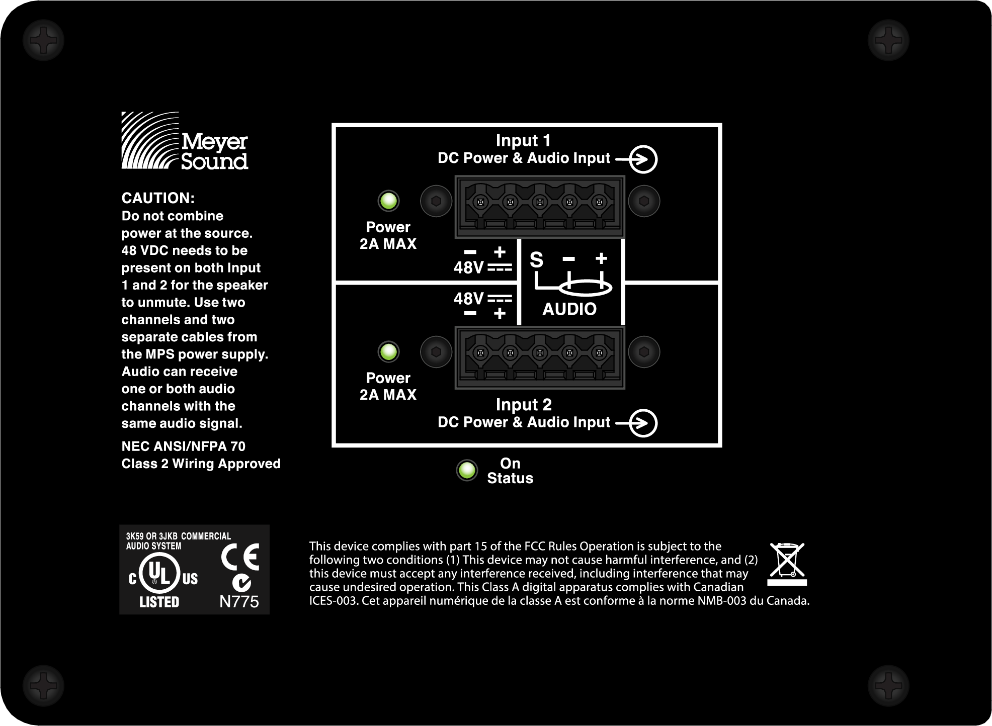 |
Dual-Channel Input Connectors (HMS-15)
The HMS-15 must be connected to a channel output pair (1–2, 3–4, 5–6, or 7–8) of the MPS-488HP using two separate composite cables. When successfully connected and receiving the required voltage, both Input LEDs for the HMS-15 turn solid green. Identical audio signals can be sent to the two inputs with no additional gain and no adverse effect. Sending different audio signals to the two inputs is not recommended and could cause one signal to be heard in the background.
HMS-15 loudspeakers ship with two Phoenix 5-pin female cable mount connectors for assembling loudspeaker cables. Separate composite cables (such as Belden 1502 or equivalent) must be used to route DC power and balanced audio to the two inputs for the HMS-15 loudspeaker. For more information, see Belden 1502 Cable (or Equivalent) and Assembling Loudspeaker Cables.
Note
If the HMS-15 does not sense power from both inputs (both Input LEDs lit) then it will not output audio.
Caution
When wiring HMS loudspeaker cables, it is extremely important that each pin be wired correctly. Make sure the 48 V DC from the external power supply is wired directly (and only) to the 48 V DC pins on the loudspeaker connector, and that the polarity is observed (negative to negative, positive to positive) to avoid damage to the loudspeaker. In addition, make sure that audio pins are wired correctly; polarity reversals for audio signals affect system performance.
Current Draw and Cable Requirements for HMS Loudspeakers
DC current draw for HMS loudspeakers is dynamic and fluctuates as operating levels change. Cabling between HMS loudspeakers and their external power supply adds resistance and hence causes a voltage drop at the loudspeakers. Because lower DC voltages compromise amplifier performance (peak SPL), and in some cases frequency response, cable resistance should be kept to a minimum.
Cable Gauge and Lengths
Cable lengths up to 150 feet between HMS loudspeakers and their external power supply are supported with only 1 dB of peak SPL loss using 18 AWG wire. Longer cable lengths are possible with heavier gauge wires, as shown in the tables below.
Cable Gauge | Resistance (Ohms/ft) | Approximate Max. Length |
|---|---|---|
12 AWG | 0.0016 | 600 ft |
14 AWG | 0.00253 | 375 ft |
16 AWG | 0.00402 | 237 ft |
18 AWG | 0.00636 | 150 ft |
20 AWG | 0.01008 | 87 ft |
Resistance (Ohms/ft) | The USW-112P compact narrow subwoofer's compact rectangular enclosure and slanted connector panel enable flushmounting of the cabinet against wall surfaces, reducing required installation depth to 12 inches, including connectors. | |
|---|---|---|
2.50mm2 | 0.0052 | 157m |
1.50mm2 | 0.01076 | 87m |
1.00mm2 | 0.02087 | 45m |
0.75mm2 | 0.03307 | 27m |

Caution
When wiring HMS loudspeaker cables, it is extremely important that each pin be wired correctly. Make sure the 48V DC from the external power supply is wired directly (and only) to the 48V DC pins on the loudspeaker connector, and that the polarity is observed (negative to negative, positive to positive) to avoid damage to the loudspeaker. In addition, make sure that audio pins are wired correctly; polarity reversals for audio signals affect system performance.
Note
For more information on cable assembly, refer to Assembling Loudspeaker Cables.
For a complete list of available cables and cable accessories from Meyer Sound, refer to HMS Accessories.
Calculating the Maximum Cable Length
The maximum cable length for an HMS loudspeaker can be calculated with the following formula:
maximum length = 2 ohms / (2 * cable resistance)
For example, the maximum length of an 18 AWG cable with a resistance of 0.00636 is 157.2 feet (2 / (2 * 0.00636)).
Belden 1502 Cable (or equivalent)
The most convenient method of wiring HMS loudspeaker cables is with a multiconductor cable such as Belden1502, which has dedicated conductors for DC power and balanced audio in a single jacket. When wiring loudspeaker cables with Belden1502 (or equivalent), use the conventions in the table below. The red and black wires are 18AWG, thicker than the other three wires, and should be used for DC power (cable lengths up to 150 feet are possible with just 1dB of peak SPL loss). The blue, white, and shield drain wires should be used for audio.
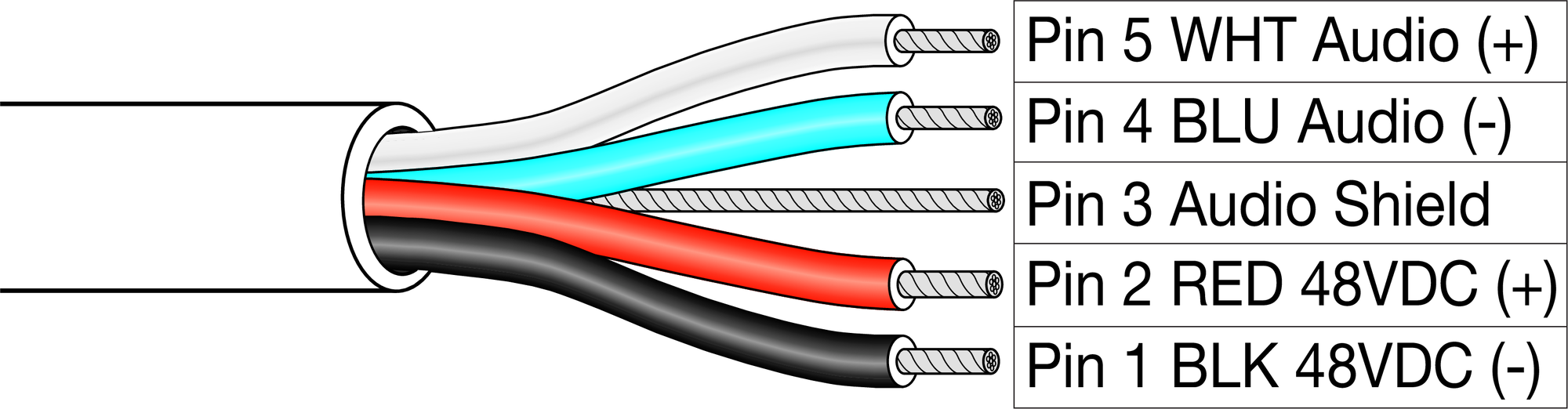 |
Belden1502 Composite Cable
Wire | Signal | Gauge |
|---|---|---|
White | Audio signal (+) | 22 AWG |
Blue | Audio signal (–) | 22 AWG |
Shield drain | Audio shield | 24 AWG |
Red | DC power (+) | 18 AWG |
Black | DC power (–) | 18 AWG |
Caution
When wiring HMS loudspeaker cables, it is extremely important that each pin be wired correctly. Make sure the 48V DC from the external power supply is wired directly (and only) to the 48V DC pins on the loudspeaker connector, and that the polarity is observed (negative to negative, positive to positive) to avoid damage to the loudspeaker. In addition, make sure that audio pins are wired correctly; polarity reversals for audio signals affect system performance.
Note
For more information on cable assembly, refer to Assembling Loudspeaker Cables.
For a complete list of available cables and cable accessories from Meyer Sound, refer to HMS Accessories.
Long Cable Runs with Separate Cable for DC Power and Audio
For installations where Belden1502 is not feasible, or for installations that require cable runs longer than 150 feet, you can use separate cables for DC power and balanced audio: a large-gauge cable for DC and a high-quality, balanced audio cable for audio. The separate cables attach to the Phoenix connector at the loudspeaker as shown in Figure. Cable runs longer than 150 feet for DC power require heavier gauge wires (larger than 18AWG); for more information, see Cable Gauge and Lengths.
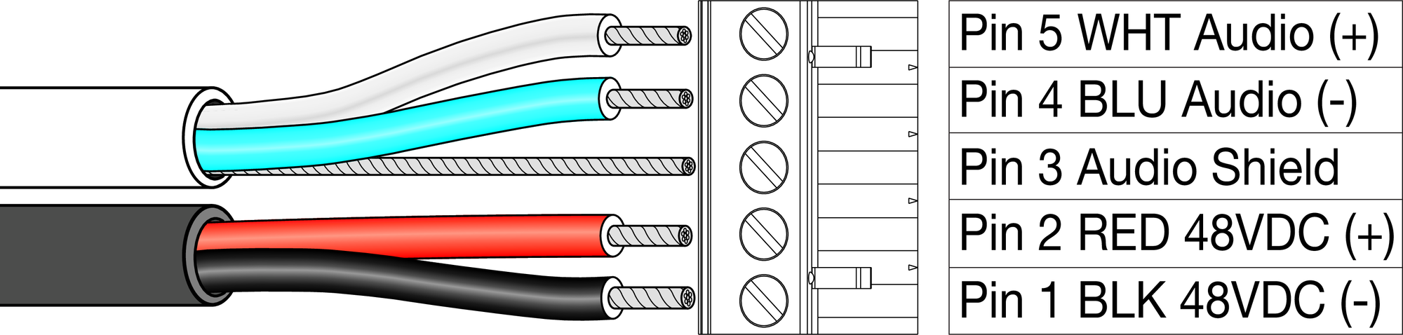 |
Separate Cables for DC Power and Balanced Audio
On/Status LED
The HMS user panel includes an On/Status LED that indicates whether the loudspeaker is operating normally (green), limiting or overheating (yellow), or clipping (red).
Note
The HMS-15 also includes two Input LEDs that indicate, when solid green, when the inputs are receiving voltage from the MPS-488HP.
Normal Operation (Green)
When powering on the HMS loudspeaker, the following startup events occur and are indicated by the On/Status LED:
The On/Status LED flashes multiple colors during its power-on sequence.
The LED turns solid green, indicating the power-on sequence has completed and the loudspeaker is ready to reproduce audio.
The LED remains green but is dimmed to eliminate any undesired glow in darkened theatres.
Caution
If after the power-on sequence the On/Status LED does not turn solid green (instead flashes multiple colors or stays solid red) and the HMS loudspeaker does not output audio, the loudspeaker has encountered an error and may need to be serviced. Contact Meyer Sound Technical Support.
CAUTION:
Note
All three LEDs for the HMS-15 (Input 1, Input 2, and On/Status) must turn solid green before it will output audio. If some or all of the HMS-15 LEDs remain unlit, or not green, verify the cabling to the MPS-488HP.
Limiting (Yellow)
The On/Status LED turns yellow to indicate limiting. When the LED is solid yellow, limiting is engaged for the high-frequency channel. When the LED flashes yellow (on and off), limiting is engaged for the low-frequency channel.
When engaged, limiting not only protects the drivers but also prevents signal peaks from causing excessive distortion in the amplifier channels, thereby preserving headroom and maintaining smooth frequency response at high levels. When levels return to normal, below the limiter thresholds, limiting ceases and the On/Status LED returns to green.
The HMS loudspeaker performs within its acoustical specifications at normal temperatures when the On/Status LED is green, or when limiting is not continuous. If limiting activity is continuous, the loudspeaker is nearing the limits of its operating capabilities where:
Increases to the input level have no effect
Distortion increases due to clipping
Drivers are subjected to excessive heat and excursion, thereby compromising their lifespan
Caution
Continuous limiting indicates that a safe, optimum level has been exceeded. If the HMS loudspeakers in a cinema installation begin to limit before reaching the desired SPL, consider adding more units to the system.
Operating Temperature
The On/Status LED also turns solid yellow when the HMS loudspeaker’s internal temperature reaches a certain level, indicating the unit is reaching its maximum heat dissipation. When the On/Status LED is yellow, a reduction in SPL is recommended. While the loudspeaker will continue to operate while the LED is yellow, the limiter threshold is lowered (causing the output level to also be reduced) to prevent the loudspeaker from overheating. When the loudspeaker’s internal temperature returns to a normal level, the On/Status LED returns to green and the limiter threshold returns to normal.
Amplifier Cooling
HMS loudspeakers rely solely on natural convection for cooling from air flowing over their heat sinks. The efficient amplifier and heat sink design keeps temperatures low, even when units are operated at high ambient temperatures and driven continuously at high output levels.
Clipping on Input (Red)
The On/Status turns red when the loudspeaker’s input stage clips, causing the amplifier to overload. When the On/Status LED is red, the source level should be reduced to avoid distortion and to avoid overloading the amplifier.
Caution
If the On/Status LED turns solid red and the loudspeaker continues to output audio, though at reduced levels, the loudspeaker’s voltage may have dropped below 25 V DC. When these conditions are encountered, operation of the loudspeaker should cease and its power supply and cabling should be verified.
Pad Switch (HMS-10 only)
The HMS-10 user panel includes a Pad switch that, when enabled, reduces the loudspeaker’s internal gain by 7.5dB, thereby lowering the loudspeaker’s noise floor. This reduces noise generated from audio sources upstream from the loudspeaker and is especially useful for close proximity listening.
 |
HMS-10 Pad Switch
Note
When the Pad switch is enabled (set to Pad), to achieve the linear peak SPL for the loudspeaker, the gain for the processor driving the loudspeaker must be increased by 7.5dB.