Interface
Operations
This section contains operational information for your reference as you proceed through these help pages. Included is an outline of a typical Spacemap System workflow, information about saving work, and an explanation of Spacemap System audio signal flow.
Typical steps to use the system
Saving in Spacemap Go
Spacemap processor control
Spacemap system audio signals
The Spacemap System controls and functions are listed below.
The System Status, Project Settings, Snapshots, and System Audio are available from any View (below).

Spacemap Go – System Status, Project Settings, Mix Snapshots, and System Audio
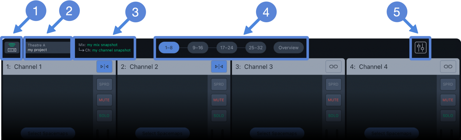
Spacemap Go – System Controls
This icon indicates the system connection status and is always visible.
If a connection problem occurs, it is indicated with the System Status icon. If the issue is not resolved within five seconds, the app opens the welcome screen. Select the system again if available. If the connection problem is resolved, the Spacemap System will appear on the welcome screen; tap to connect again. If the GALAXY processor(s) did not lose power, all the settings will remain untouched, even if any modifications were not saved.

Spacemap Go – System Connection Status
Tap the System Status icon to select another Spacemap System if there is more than one available. If no real or virtual GALAXY processors are discovered in Spacemap Mode, a connection message is displayed. On the right, links to provide feedback, Spacemap Go online Help, and the Meyer Sound website are provided.
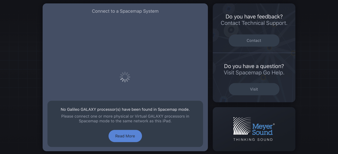
Spacemap Go – No Galileo GALAXY Processor Found in Spacemap Mode.
The System Connection window lists the Spacemap Systems available on the Network. If a System is not yet configured, the system is listed as Unconfigured. Tap a system name to configure that system.
Note
The Spacemap System Name is the Group Name entered for each processor in Compass software.
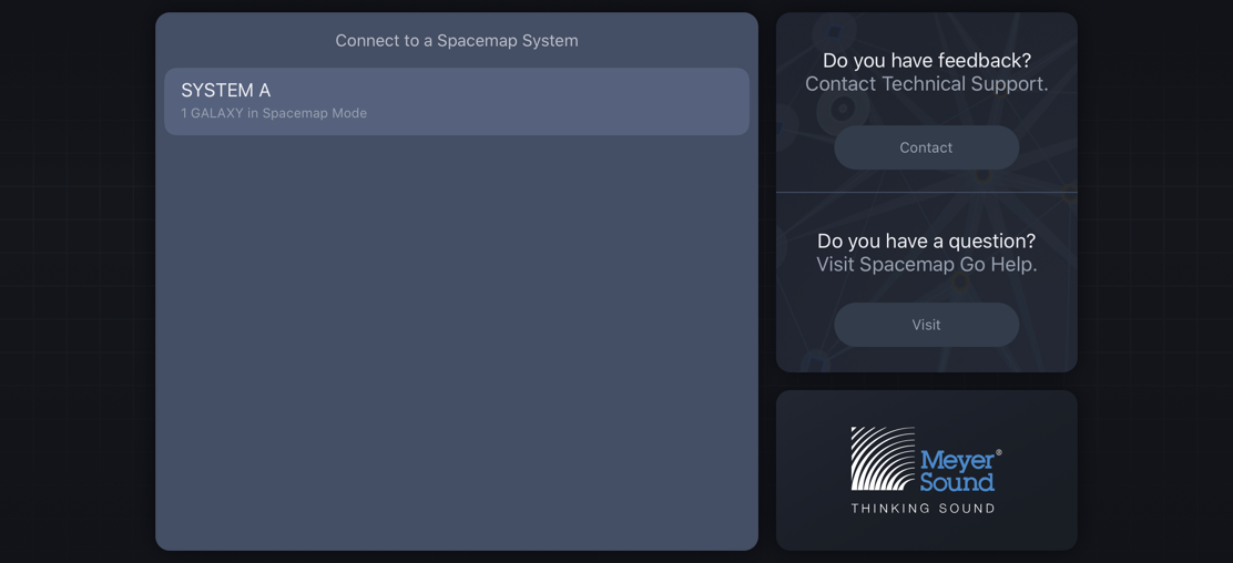
Spacemap Go – Available Spacemap Systems
System configuration wizard
The GALAXY processors of a system are listed. Tap each processor that has analog or AES3 inputs. Adjust the quantity of combined analog and AES3 inputs for each processor. Tap PROCEED if no analog or AES3 inputs are used.
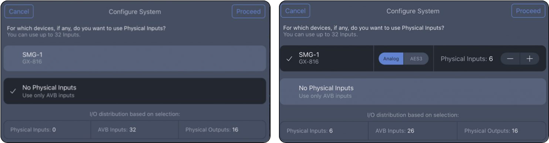
Spacemap Go – Select Processors with Analog or AES3 Inputs, Select Total Number of Analog and AES3 Inputs for Each Processor
Adjust the number of AVB inputs used in the system. Tap SAVE TO SYSTEM. The input configuration is complete.
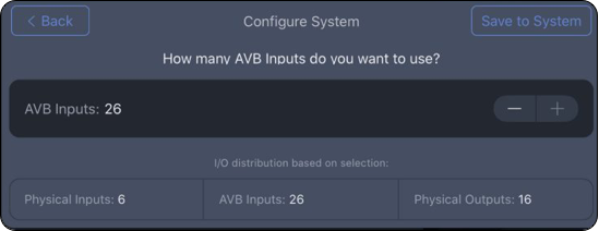
Spacemap Go – Adjust the Number of AVB Inputs
To modify the input configuration, tap SETTINGS VIEW. Select INPUT on the left, and tap RECONFIGURE INPUTS in the upper-right corner.
Displays Spacemap Go System Name and Project Name. Tap to open Project Settings pop-over menu (details are on the Project Settings page).
Displays the current Mix and Channel Snapshot names. Tap to switch to Setlist View.
Spacemap Systems have up to 32 channels. These channels are grouped in 4 layers. Each layer displays 8 channels. Tap a group to display the layer.
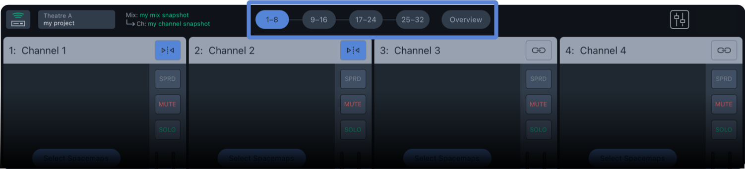
Spacemap Go – Layer Selection for Channels
The Overview option plots all 32 of the Spacemap Panner locations. Tap the Channel numbers on the left to show/hide individual Channels. One Spacemap can be selected and viewed when the SHOW SPACEMAP option is enabled.
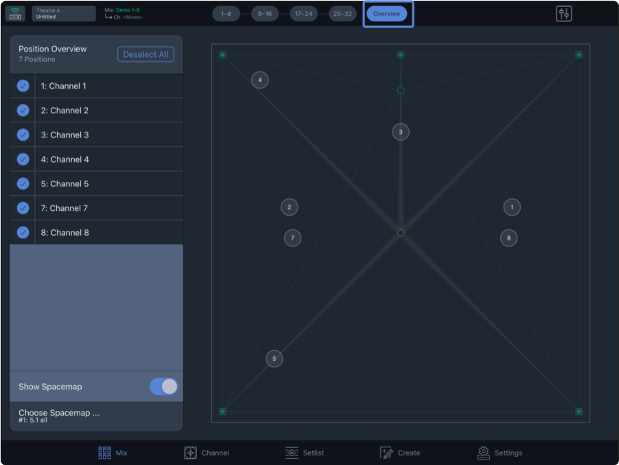
Spacemap Go – Mix View, Overview
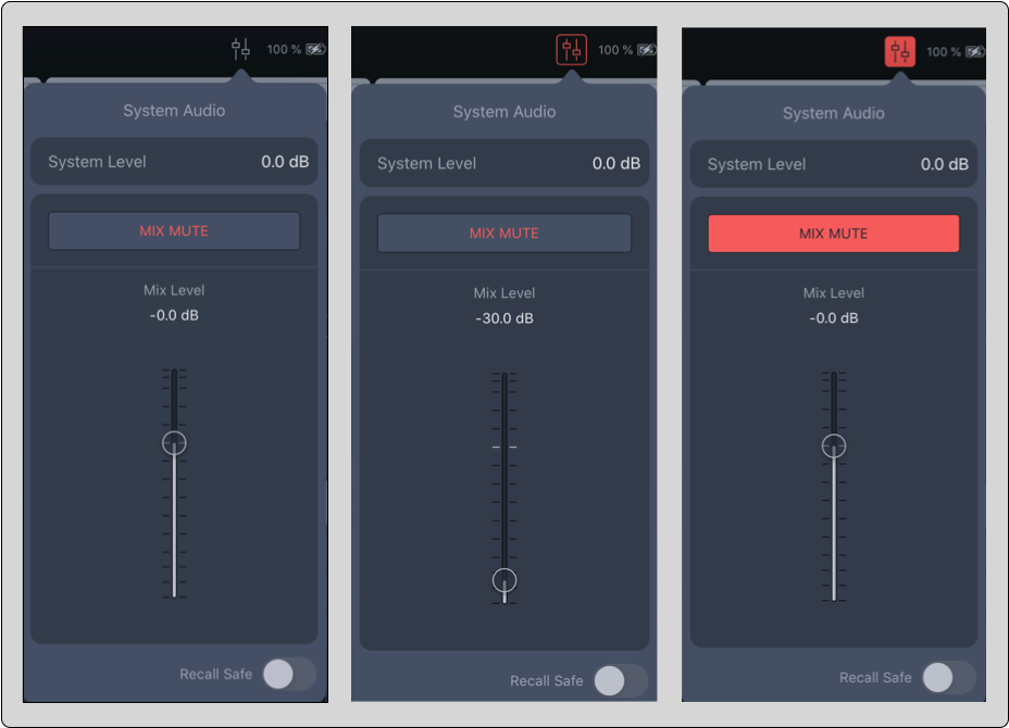
Tap the  icon to open the System Audio popover. The color of the icon changes to red when the Mix Level is less than -30 dB and is filled red when the Mix Mute is engaged.
Spacemap Go – System Audio Popover
System Level
The System Level is stored with a System Snapshot. Use the System Level as an offset so the Mix Fader can be set near nominal when the system is operating at the desired output level.
Mix Level
The Mix Level and Mix Mute are stored with a Mix Snapshot. The Mix Level is intended for fine level adjustment during a performance. It is helpful to adjust the System Level so the Mix Level is near nominal (0 dB) for better fader resolution.
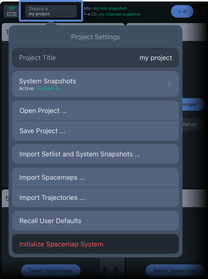
Project settings
The Project Settings button displays the Spacemap Go System name and the Project Name. Tap the button to open the menu.
Important
Do not store or recall Snapshots with Compass software or Compass GO while operating a Spacemap System. The Spacemap Go app manages the storage and recall of GALAXY processor settings.
Projects are the upper-most level of saving a Spacemap System, capturing all the parameters of a Spacemap System. When a Spacemap Go Project is saved, the System Snapshot, Mix Snapshot, User and Factory Defaults and the System Configuration are saved.
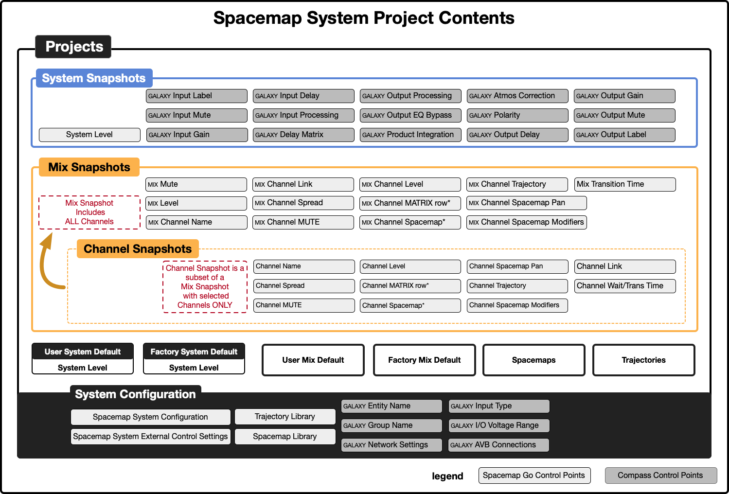
Spacemap Go – Project Contents and Organization
Spacemap Go – Project Settings
Project title
Tap PROJECT TITLE to edit or enter a new name.
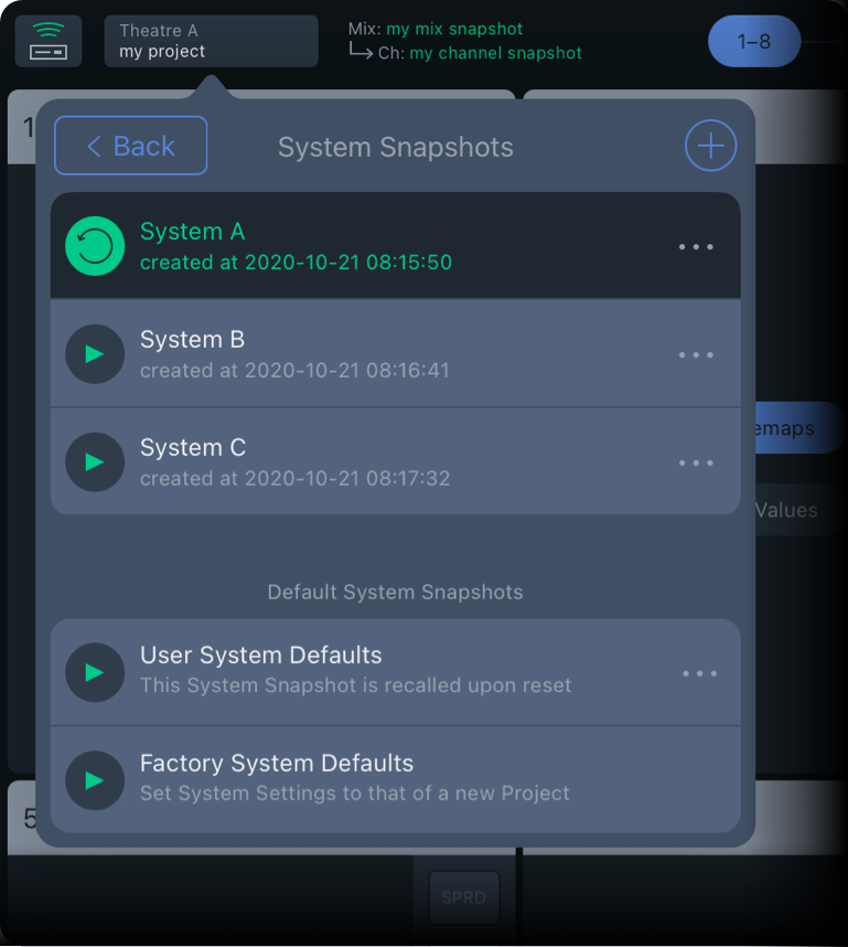
System snaphsots
System Snapshots include the System Level, the GALAXY input and output processing, and the delay matrix control points. Tap to reveal controls to create new, delete, and update System Snapshots.
To store a new System Snapshot, tap and enter a name. Tap CAPTURE to finish.Tap the More icon (three-dots) to reveal controls to update the current System Snapshot with the current changes and display the System Snapshot details and External Recall ID number.
Spacemap Go – Project Settings, System Snapshot
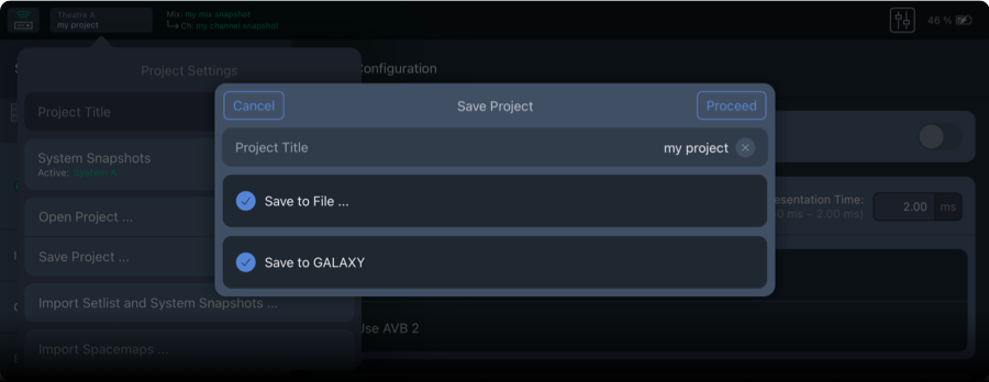
Open and save a project
Tap OPEN PROJECT to open the desired file. Use the iPadOS browser to locate and open a Spacemap Go Project file.
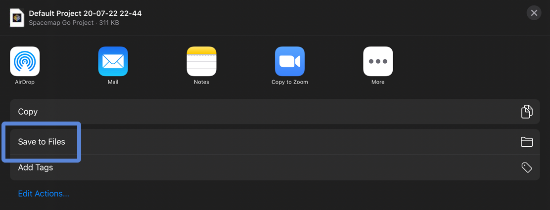
Tap SAVE PROJECT to save or share a Project. Name the Project and select whether to save the file on the iPad, the GALAXY hardware, or both. One Spacemap Go Project can be saved to the hardware of the GALAXY processor(s).
This Project can be recalled when the system is powered on and LOAD PROJECT FROM GALAXY ON RESTART is selected (System Settings, System Configuration).
Spacemap Go – Save Project to iPad Files and GALAXY Hardware
The overlay offers different ways to share the file (via AirDrop, mail, messages, etc.). To save the Project file on the iPad, tap SAVE TO FILES and select a folder.
iPadOS – File Save Dialog
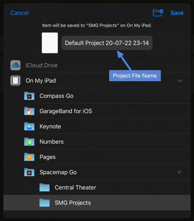
The app creates a Spacemap Go folder for convenience. To change the default file name, tap the Project name.
iPadOS – Save Project to On My iPad/Spacemap Go/SMG Projects
Import setlist and system snapshots
Tap to select a Spacemap Project from which to import the Setlist and System Snapshots. The imported Snapshots are added to the Snapshots already in the Project.
Import spacemaps and trajectories
Tap IMPORT SPACEMAP or IMPORT TRAJECTORY, then select the Spacemap or Trajectory file(s) to import. The imported Spacemaps or Trajectories are added to the Spacemap or Trajectory Library.
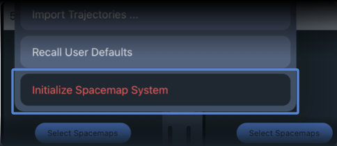
Recall user defaults
Tap RECALL USER DEFAULTS to recall the User System Defaults Snapshot.
Use the Setlist View controls to recall or update the Default Mix Snapshots. Tap the SHOW button in the Setlist View to reveal the Mix Default Snapshots. Tap the More menu (three-dots) to update the User Mix Defaults Snapshot.
Initialize a Spacemap system
Tap INITIALIZE SPACEMAP SYSTEM to restore the original state of the app. The Mix and System Snapshots, Spacemaps and Trajectories will be deleted and replaced with the defaults.
Spacemap Go – Project Settings, Initialize Spacemap System
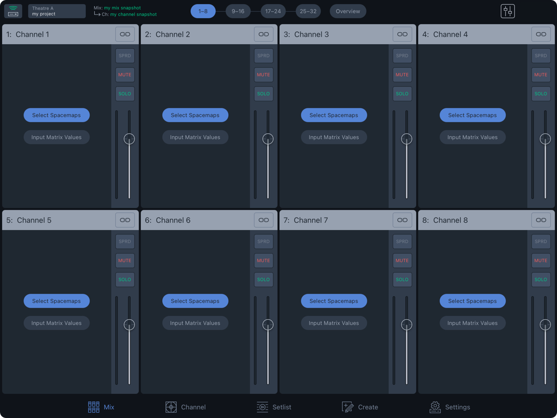
Mix view
The Mix View presents common controls for 32 Spacemap Channels. For all controls of a channel, use Channel View.
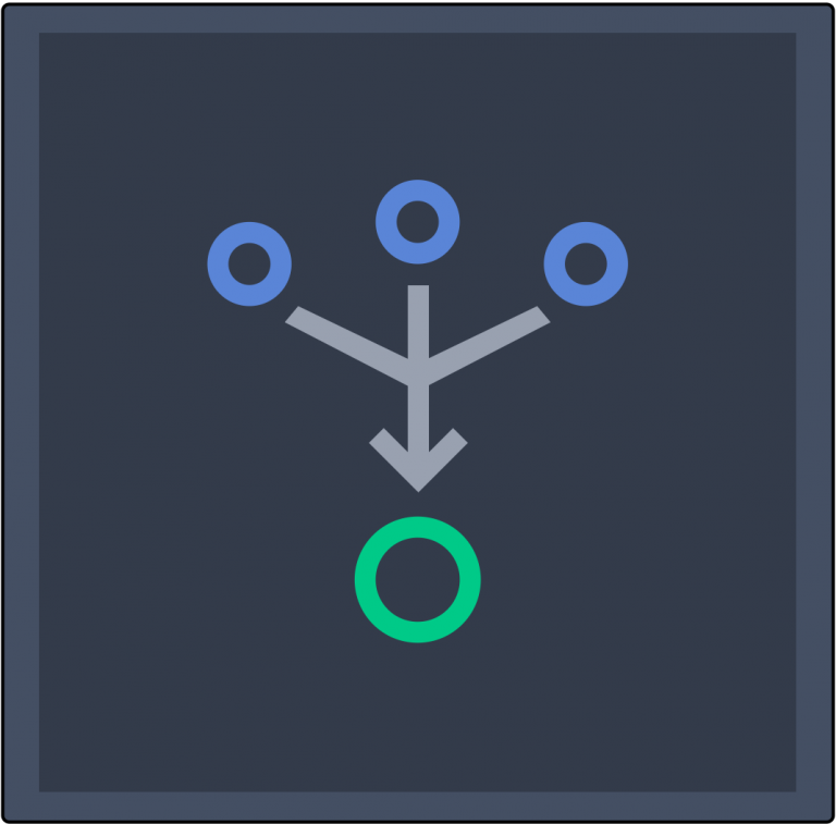
Each Channel represents an input. There are three methods used to route an input signal to outputs:
Real-time gesture control of the Spacemap Panner
Automated control, using a Trajectory (predefined path) that the Spacemap Panner follows
Enter summing matrix cross-point levels (Channel View)
By default, Spacemaps are not selected and Matrix levels are set to -inf dB (off) — no path for audio exists between a system input and an output. This default state is similar to a mixing console input that is not assigned to any buses, matrix outputs, or master outputs.
Select a Spacemap
The Mix View displays eight input channels per layer, up to four layers, 32 channels, as well as an Overview of all channels. The eight active channels are highlighted, Channels 1-8 below.
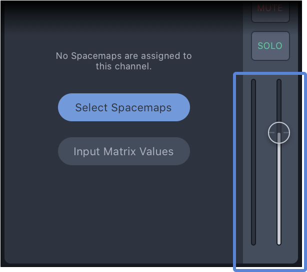
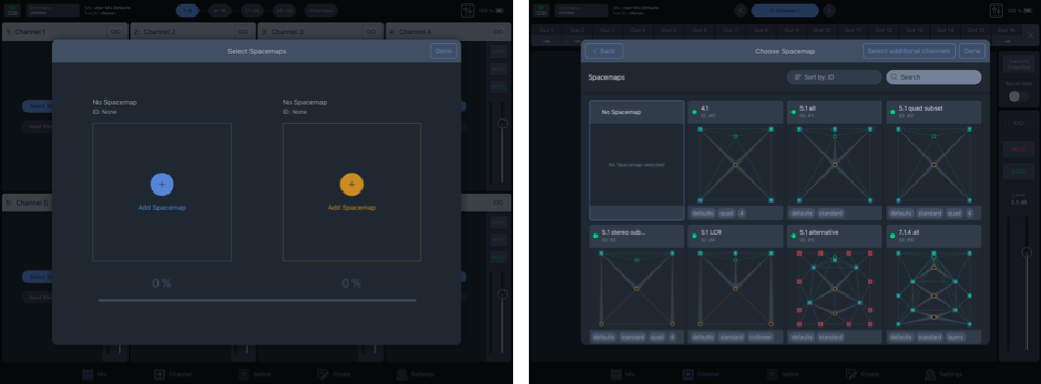
Tap the SELECT SPACEMAPS button to choose a Spacemap for a channel.
Spacemap Go – Mix View
Tap the ADD SPACEMAP button and select a Spacemap from the Choose Spacemap popover. Select APPLY TO ALL CHANNELS to assign the selected Spacemap(s) to all channels.
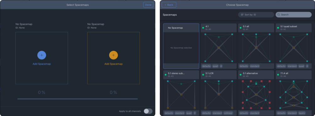
Spacemap Go – Select Spacemaps Window and Spacemap Library
Two Spacemaps can be selected for each channel. Tap the orange ADD SPACEMAP button to add a second Spacemap.
When two Spacemaps are added, use the percentage slider to change the percentage of the input signal sent to each Spacemap. The slider changes color depending on which Spacemap has the higher percentage, although both are routing audio unless the percentage is 0% for one of them. For example, using two Spacemaps, one Spacemap for lateral Speaker Nodes and another for overhead Speaker Nodes, fading between the two Spacemaps pans the input vertically. See details on the Spacemaps page.
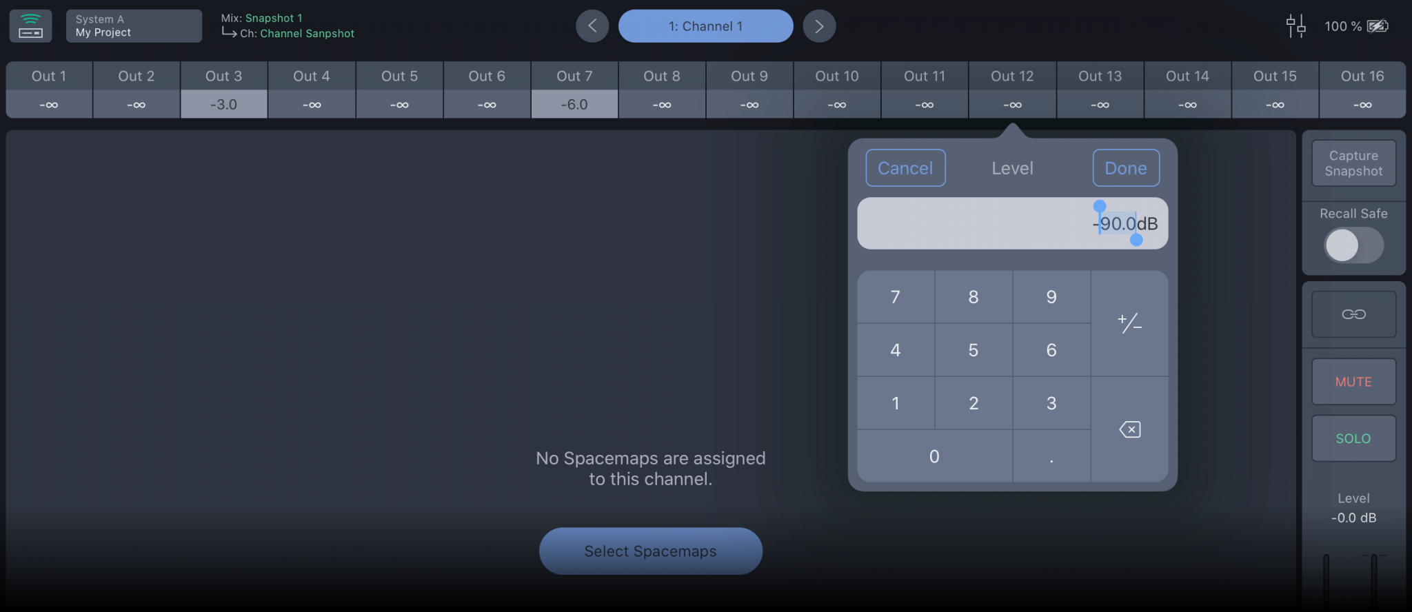
Channel matrix values
The second option for routing an input to outputs is to enter cross-point Matrix levels. From the Mix View, tap the name of a channel or tap the Channel View button to open the Channel View. Use the arrows on either side of the channel name in the channel navigator to switch to the previous or next channel. Tap the channel name to open the channel selector pop-over and select another channel. Tap a matrix level to enter the output level for the channel. Swipe the Matrix row for additional outputs.
Spacemap Go – Channel Matrix Levels
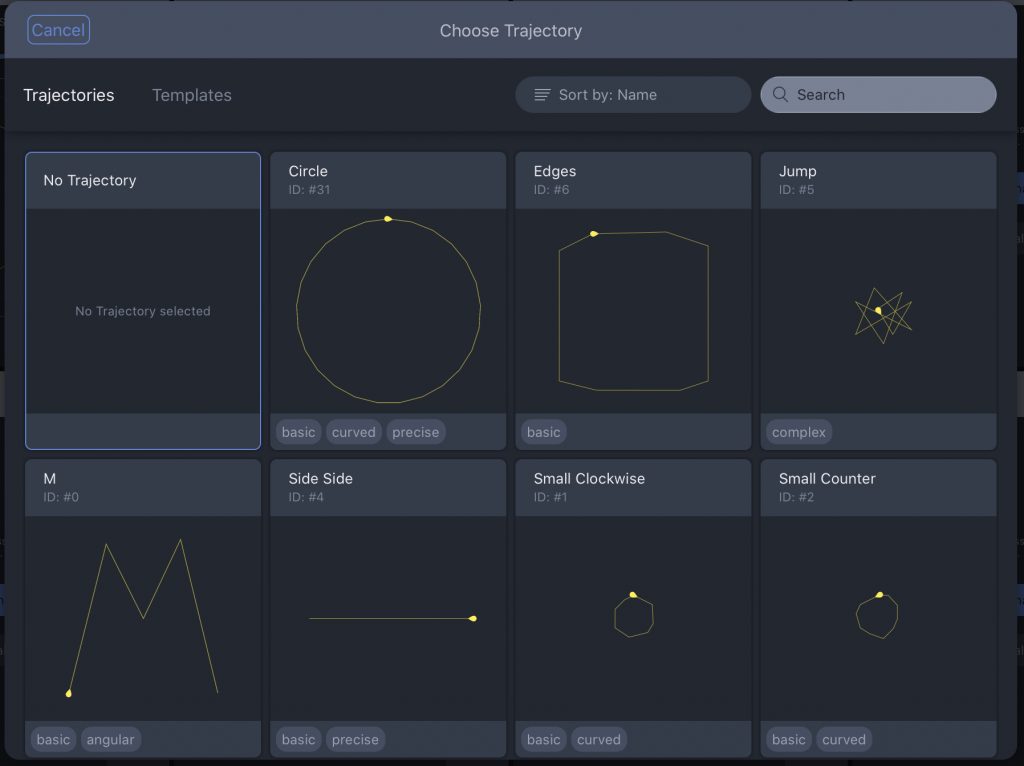
Select a Trajectory
Trajectories are automated motion paths for the Spacemap Panner. When a Spacemap is assigned, the CHOOSE TRAJECTORY button is added below the Spacemap. Tap it to display the Trajectory Library. Tap a Trajectory to add it to the Spacemap.
Spacemap Go – Trajectory Templates
From the Mix View, two controls are displayed below the Spacemap: one to play the Trajectory and another to reset the Trajectory. Tap the Trajectory Name next to these controls to open the Trajectory Library and select a different Trajectory or none.
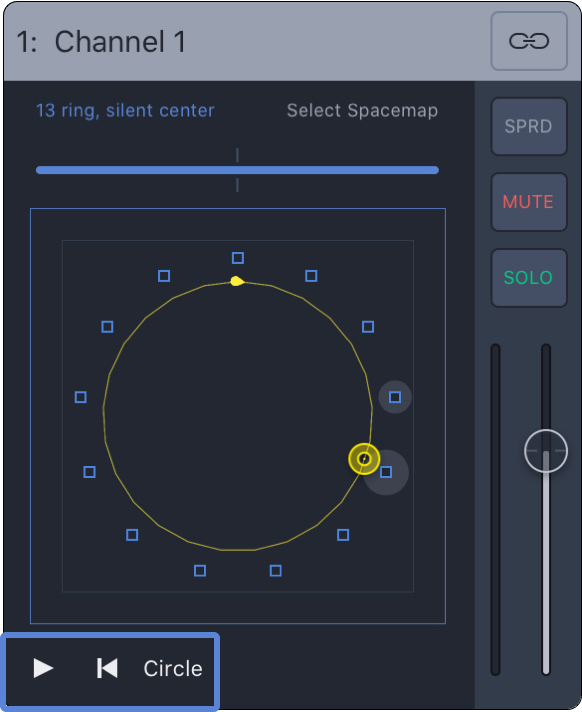
Mix View – Trajectory Controls
Remove a Spacemap or trajectory
To remove a Spacemap or trajectory from a channel, follow the same steps to add a Spacemap or trajectory and select NO SPACEMAP or NO TRAJECTORY from the library.
Mix or Channel View – Select No Spacemap or No Trajectory
Channel controls
Each channel has the following controls:
Input Level Meter: Visual indication of the input level.
Fader: Adjusts the audio level using a logarithmic slider. The nominal level (0 dB) is indicated by the grey line.
Mix View – Channel Signal Meter and Level Fader
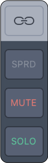 | Link: Tap this button to link the Fader Level, Solo, Mute, and Spread controls of odd/even channel pairs. Select a link mode for the Spacemap Panner – see options below. Select a Trajectory for the odd numbered channel of a linked pair. The Panner of the even numbered channel will follow the Trajectory of the odd channel depending on the link mode selected. |
SPRD: Regardless the Spacemap Panner position, the spread function routes an input signal to all of the Speaker Nodes in a Spacemap. Tap the SPRD button to open the percentage slider. At 0%, no additional signal is sent to Speaker Nodes. As Spread is increased, the surrounding nodes without signal start receiving the input signal. When Spread is set to 100%, all the Speaker Nodes receive the input signal at 0 dB, no attenuation. | |
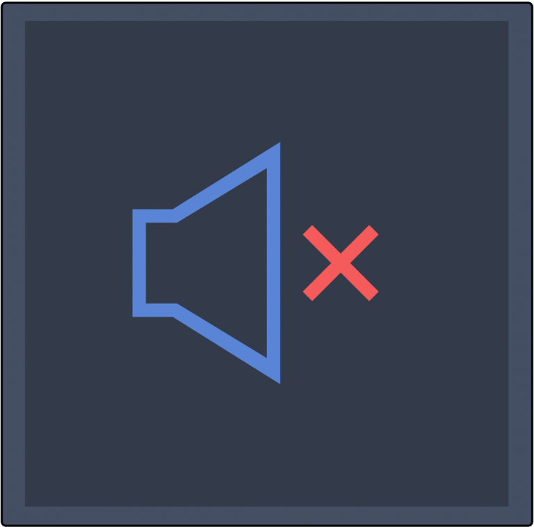
MUTE: When MUTE is selected, audio is no longer routed to outputs from the channel. | |
SOLO: When SOLO is selected, only audio from the selected Channel is routed to outputs, commonly referred to as Solo In Place. |
MONO: Both linked channels have the same behavior.
NEAR X: The even channel follows the odd channel, but is offset horizontally to the right.
NEAR Y: The even channel follows the odd one, but is offset vertically from the top.
FAR X: The even channel follows the odd channel, but is offset horizontally further to the right.
FAR Y: The even channel follows the odd one, but is offset vertically further from the top.
MIRROR X: When the X value is positive for the first linked channel, the X value is negative for the second, and vice versa.
MIRROR Y: When the Y values are positive for the first linked channel, the Y values are negative for the second, and vice versa.
MIRROR XY: Both X and Y values are mirrored as described above.
Tip
When linked, the even channel indicates the linked status.
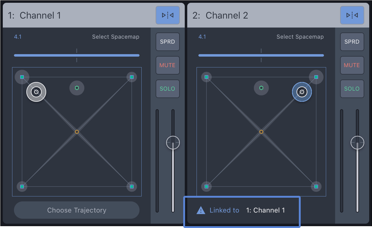
Mix View – Linked Channels
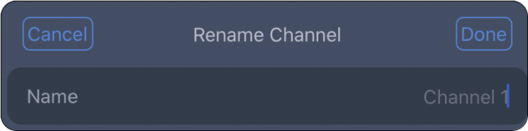
Channel name
Tap-hold the channel label to change the name. A popover window opens; edit the name, and tap DONE.
Mix View – Rename Channel Pop-Over
Channel view
The Channel View presents all of the controls for a single Spacemap Go channel to the user.
Fundamentally, Spacemap Go controls the Summing Matrix cross-point levels of Galileo GALAXY processors. Each Spacemap Go Channel represents a GALAXY processor input. Each input can be routed to any output at any level between -inf and 0 dB. The system outputs are represented as Speaker Nodes in the app.
For each channel, the Summing Matrix cross-point levels can be changed using one of three methods:
Real-time gesture control of the Spacemap Panner.
Automated control, using a Trajectory (predefined path) that the Spacemap Panner follows.
Enter summing matrix cross-point levels.
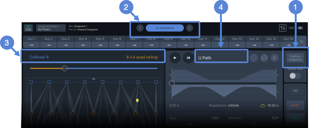
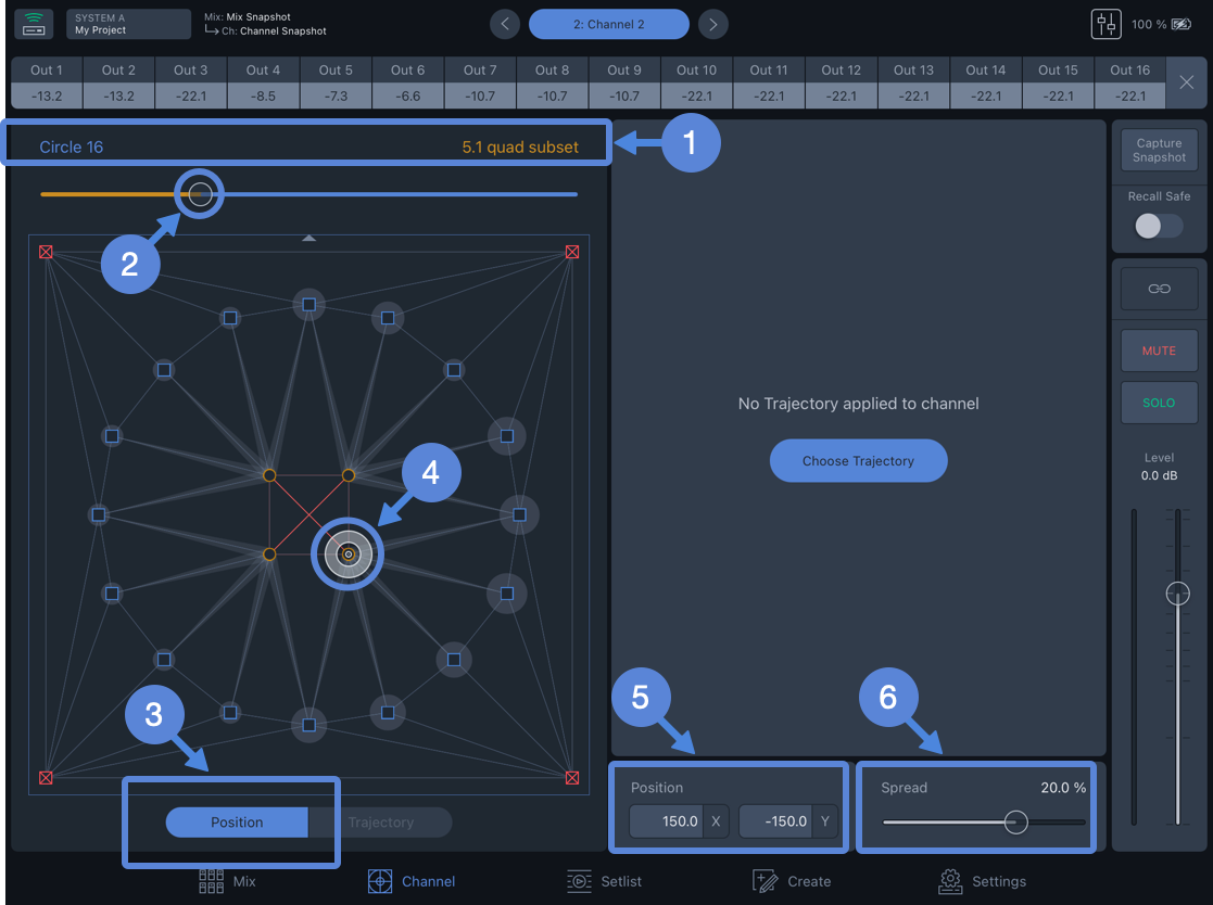
Channel View – Capture Channel Snapshot(1), Channel Navigation(2), Spacemap A & B (3), and Trajectory (4)
The settings of individual channels or groups of channels are stored and recalled using Channel Snapshots (Mix View). Individual Channel Snapshots can be created in the Channel View by tapping the Capture Snapshot button,  above.
Use the navigation buttons to display the next or previous channel,  above. Tap the channel name to open the channel selection pop-over. Tap-hold the channel name to edit.
Each channel can have one or two Spacemaps  and one Trajectory,
  above.
Tap the name of a Spacemap or Trajectory to open the library, make another selection or select none.
Summing matrix levels
For each channel, tap an output to manually enter a summing matrix cross-point level, routing the input signal of the channel to the selected processor output at the level entered. Swipe left/right to display additional outputs. Levels entered are overwritten if a Spacemap is added to a channel and the Panner is moved.
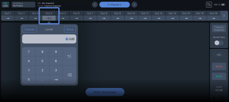
Tap Output to Enter Summing Matrix Cross-point Level
Add Spacemaps
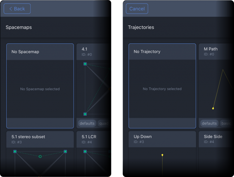
Channels do not have Spacemaps selected initially. Each channel can use two Spacemaps. To select Spacemaps for a channel, tap in Mix View or Channel View. Then, tap either of the Add Spacemap buttons (below, left) to open the Spacemap library, which includes factory examples and user created Spacemaps (below, right). Swipe up/down to scroll the Spacemap library.
Use the Create View to add user-created Spacemaps to the Snapshot Library.
Select Spacemaps Pop-Over – Tap Either ADD SPACEMAP Button (left), Spacemap Library, Select a Spacemap (right)
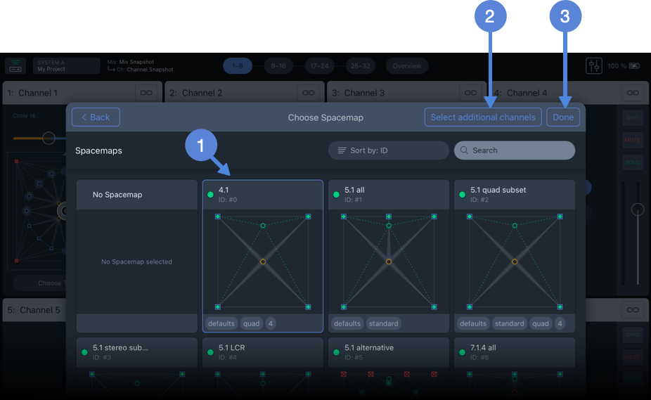
Choose Spacemap Pop-Over – Tap a Spacemap, SELECT ADDITIONAL CHANNELS or DONE to Add the Spacemap to the Channe
Tap a Spacemap to select it, above, then tap SELECT ADDITIONAL CHANNELS to add the Spacemap to multiple channels or tap DONE to add the Spacemap to the channel.
Channel View, Two Spacemaps Assigned, No Trajectory
SPACEMAP NAME: Tap either to make a different selection, including none.
PERCENTAGE: When two Spacemaps are added, this slider adjusts the percentage of input signal routed to each Spacemap. The slider changes color and the Spacemap displayed changes depending on which Spacemap has the higher percentage, although both are receiving signal unless the percentage is zero for either one. There are advantages to using two Spacemaps; see details on the Spacemaps page.
POSITION MODE: Enables gesture control of the Spacemap Panner .
 XY POSITION: Displays the X and Y coordinates of the Spacemap Panner. Tap values to enter coordinates
 SPREAD: Controls how much of the input signal to routed to all of the speaker nodes in the Spacemap, regardless of the Spacemap Panner location. When set to 0%, no signal is “spread.” As the Spread percentage is increased, the level of the input signal routed to each Speaker Node is increased. When 100% is selected, the input signal is routed to all Speaker Nodes at 0 dB. This slider is logarithmic.
Add a Trajectory
Use the Create View to add user-created Trajectories to the Trajectory Library.
A Trajectory is a defined movement path for the Spacemap Panner. When a trajectory is selected, a yellow line representing the movement path is overlaid on the Spacemap, and the Trajectory controls are displayed on the right side of the Channel View.
Channels do not have Trajectories selected initially. Each channel can be assigned one Trajectory. To select a Trajectory for a channel, tap in either Mix or Channel View to open the Trajectory library, which includes factory examples and user-created Trajectories. Swipe up/down to scroll the Trajectory Library.
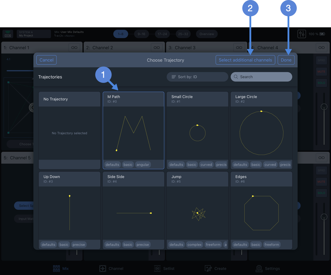
Select Trajectory Pop-Over – Tap a Trajectory, SELECT ADDITIONAL CHANNELS, or DONE to Add the Trajectory to the Channel.
Tap a Trajectory to select it, then tap SELECT ADDITIONAL CHANNELS to add the Trajectory to multiple channels, or tap DONE to add the Trajectory to the channel.
Channel View – Trajectory Controls
PLAY: Starts the Spacemap Panner following the Trajectory.Restart: Stops the Trajectory, if playing, and resets the play head to the beginning of the Trajectory timeline.
TRAJECTORY: Tap to select another Trajectory or none.
RESET: Opens pop-over, select: Reset All, Rate, Scale, or Offset. CHOOSE ANOTHER: Tap to select another Trajectory or none.REMOVE: Removes the Trajectory from the channel.
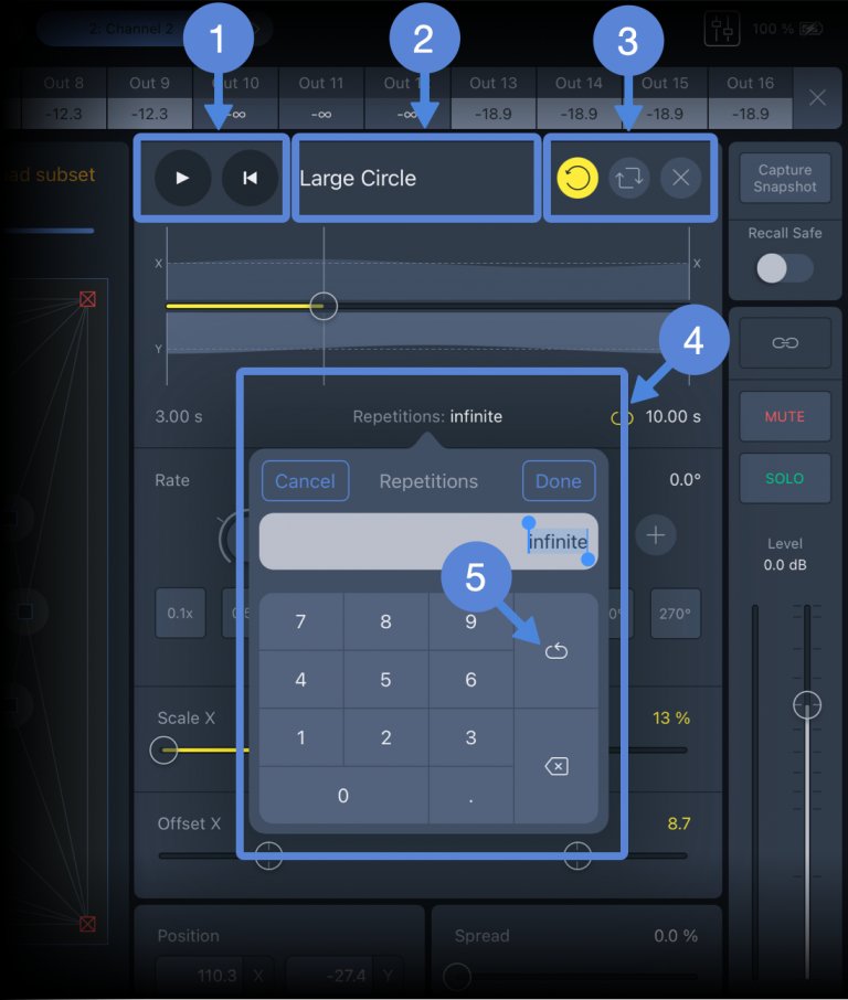
REPETITIONS opens pop-over, enter number of times to repeat or infinity .
Tap the TRAJECTORY button to enable gestures to modify the Trajectory path overlaid on the Spacemap.
Use one-finger gestures to move the Trajectory, two-finger pinch/expand to scale, and two-finger twist to rotate.

Trajectory Movement
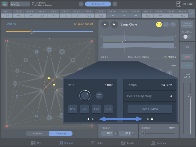
To switch between Rate and Tap Tempo controls, swipe left/right on the pane.
Channel View – Swipe Left/Right to Switch Between Rate and Tap Tempo Controls
RATE: Changes the speed the Trajectory is played. Tap-drag the encoder up/down to change the Rate.
REVERSE DIRECTION: Immediately reverses the direction the Panner travels along the Trajectory.
TEMPO & BPT: Change the Trajectory rate based on BPM or Beats/Trajectory. Tap to edit values.
TAP TEMPO: Tap repeatedly to set Tempo BPM manually – continue tapping until the Tempo BPM updates.
Channel View, Trajectory – Timeline and Rotation, Scale, and Offset Controls
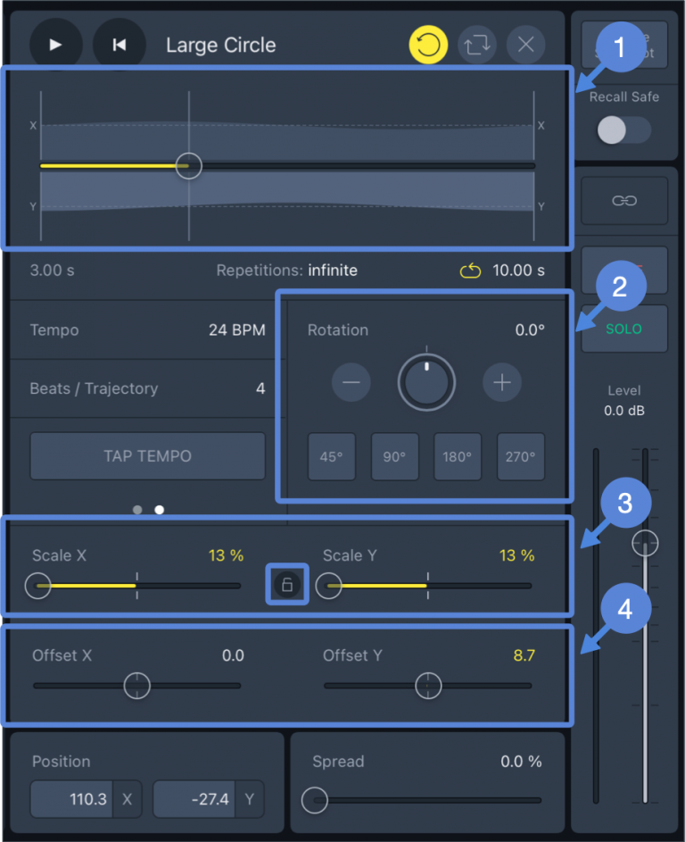
TIMELINE: All changes are reflected on the Trajectory Timeline. The graphic consists of three horizontal axes; the middle represents the time of the trajectory. The other two depict the X and Y coordinates of the Panner.
ROTATION: To rotate the Trajectory, use the encoder, the plus/minus buttons, or tap a preset value.
SCALE: To change the Trajectory size, use the Scale X and Scale Y controls. Tap the Lock icon to link the Scale X and Y values absolutely.
NOTE: If the Spacemap area is exceeded by the Trajectory, it will change shape, respecting the boundary.
Channel controls
Channel View, Duplicate Controls Available in Mix View
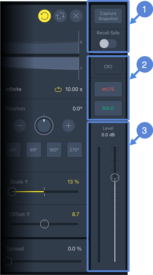
CAPTURE SNAPSHOT: Creates a new Channel Snapshot, which includes: Channel Name, Link, Spread, Mute, Level, Matrix levels, Spacemap, Spacemap Pan, Trajectory and Spacemap modifiers.
RECALL SAFE: Prevents overwriting of the channel settings when either type of Snapshot is recalled. The Recall Safe state is not stored when Channel Snapshots, Mix Snapshots, or Projects are created or saved.
LINK, MUTE, SOLO: Are duplicate controls, also available in Mix View.
LEVEL and INPUT METER: Are duplicate controls, also available in Mix View.
Setlist view
The Setlist View facilitates storing and recalling Mix and Channel Snapshots and is usually used during a performance to recall individual Channel settings or groups of Channel settings.
Mix and channel Snapshots
A Mix Snapshot stores the parameters for all Channels plus the Mix Level and Mute.
A Channel Snapshot stores the parameters of an individual Channel.
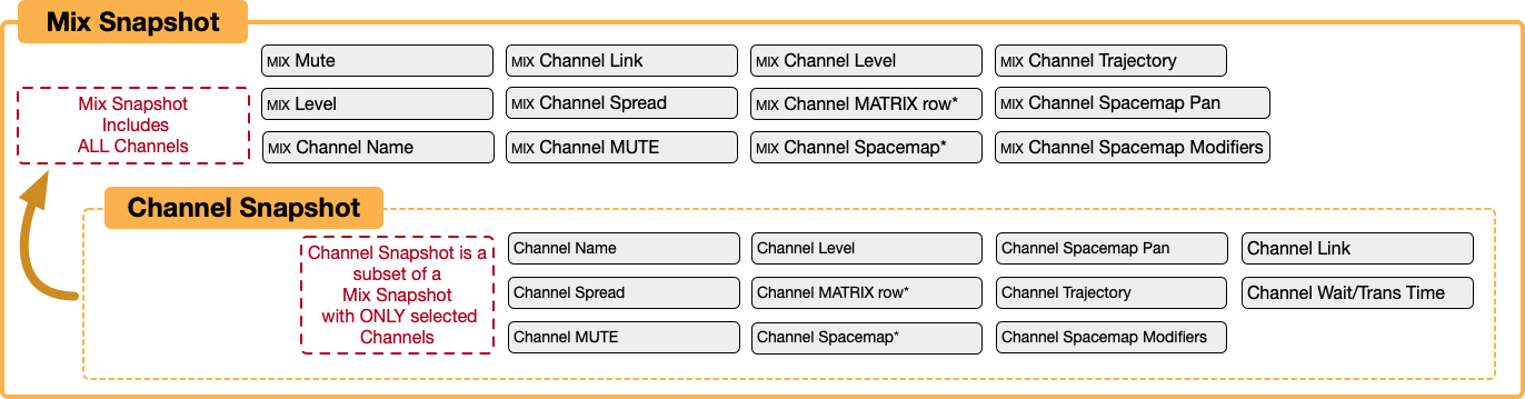
Saving Hierarchy – Channel and Mix Snapshots
Overview
The Setlist View displays the Mix and Channel Snapshots in two panels. If the Mix Snapshot panel is hidden, tap button  below to reveal.
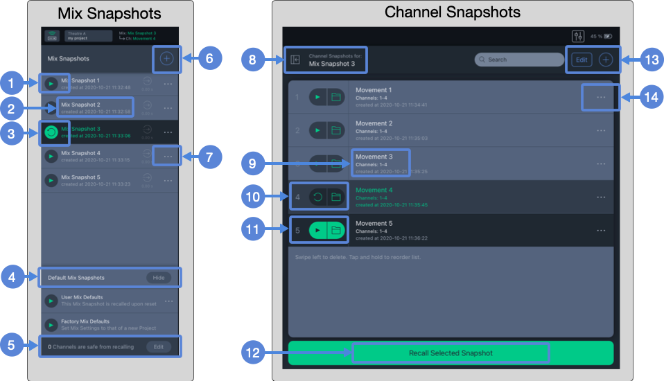
Setlist View – Mix and Channel Snapshot Panels
Recall this Mix Snapshot with confirmation
Mix Snapshot name and comment
Most recent Mix Snapshot Recalled. Tap  to recall the Mix Snapshot again.
Default Mix Snapshots show/hide
Number of Channels with Recall Safe Enabled
Capture new Mix Snapshot
 Opens popover to update or display Mix Snapshot details, view external recall ID#
Collapse/Expand Channel Snapshot panel
 Channel Snapshot name, included Channels, and comment
 Most recently recalled Channel Snapshot indicated by grey background. Tap again to recall.
 Selected Channel Snapshot. Tap PLAY button or Recall Selected Snapshot button
  to recall.
Recall selected Channel Snapshot
 Tap EDIT to group/ungroup, move, or delete Channel Snapshot;
  to create new Channel Snapshot.
 Update Channel Snapshot, update group, ungroup, edit details, or view external recall ID#
Mix Snapshots
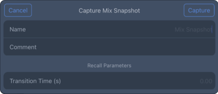
To capture a new Mix Snapshot, tap the plus button , to open the popover. Enter a name for the snapshot and tap CAPTURE. The new snapshot will be added to the Mix Snapshots list.
Setlist View – Capture Mix Snapshot Popover
Update a mix Snapshot
If changes are made to one or many channels, and the settings stored in a Mix Snapshot need to be updated, tap the three-dot icon next to the Snapshot Name, then UPDATE MIX SNAPSHOT. Any Mix Snapshot can be updated with the current settings of all the channels.
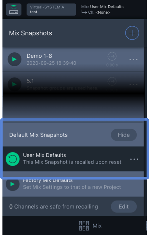
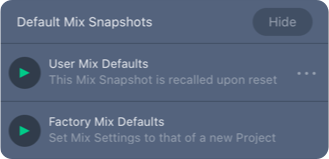
The Mix Snapshot column also lists the Default Mix Snapshots , which are hidden by default. Tap the SHOW/HIDE button to toggle the User and Factory Defaults display. There are two types of Mix Defaults:
User Mix Default: An additional, user-defined Mix Snapshot, used as a starting point at the beginning of a project or the start of a day. Tap the three-dot icon and select UPDATE MIX SNAPSHOT to update the stored parameters of all channels. This snapshot is recalled when the app connects to a Spacemap System.
Factory Mix Default: Mix Snapshot that returns all channels parameters to nominal, no Spacemaps assigned, and all matrix levels set to -∞ dB.
Setlist View – Default Mix Snapshots
The total number of channels that are set to Recall Safe is displayed . Tap EDIT to select channels to recall safe.
Recall mix Snapshot
Tap the Play Button to overwrite all the channels with the parameters stored in the Mix Snapshot. Tap RECALL to accept, CANCEL to decline. When a Mix Snapshot is recalled, the Play Button changes to a circle with an arrow at the end ; tap to recall the Mix Snapshot again.
Mix Snapshot options
Tap the three-dot icon to open the More pop-over to view these options:
Tap UPDATE MIX SNAPSHOT to overwrite the settings currently stored in the snapshot.
Tap UPDATE MIX SNAPSHOT to overwrite the settings currently stored in the snapshot.
Tap MIX SNAPSHOT DETAILS to edit the name, add a comment, or exclude channels when the snapshot is recalled. The external recall ID number is listed (for external control).
To exclude a channel, tap NONE (below) and select channels from the list to exclude them when the Mix Snapshot is recalled.
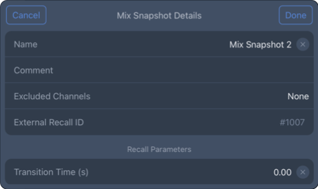
Setlist View – Mix Snapshot Details
Tap INCLUDED CHANNEL SNAPSHOTS to preview the Channel Snapshots without recalling the Mix Snapshot.
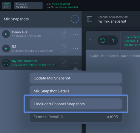
Setlist View – List Channel Snapshots in Mix Snapshot
Channel Snapshots
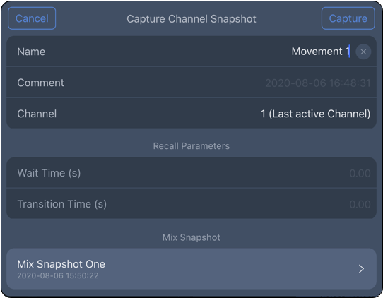
Setlist View: To store a Channel Snapshot, tap the ADD button . The Capture Channel Snapshot popover opens. Add a name and comment. Then tap CHANNEL to select the channels to include. Enter Wait and Transition Times if an immediate change is not desired. Tap CAPTURE to save a Channel Snapshot.
Channel View – Add Channel Snapshot
Channel View: Channel Snapshots are also saved/captured in Channel View. Tap the CAPTURE SNAPSHOT button (below). The Capture Channel Snapshot popover opens. Make the same entries and selections as above and select the Mix Snapshot with which to associate the Channel Snapshot.
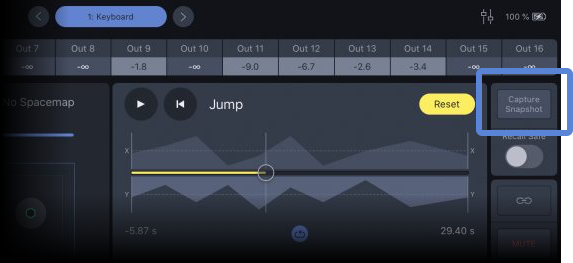
Channel View – Capture Snapshot Button
Group, move, and delete Snapshots
Tap the EDIT button and select Channel Snapshots to group/ungroup, move, or delete. Tap the desired action at the bottom of the pop-over. When GROUP is selected, a popover opens to name the Channel Snapshot Group. Groups are identified by a folder icon (FX 1 below) instead of displaying the channel number (Movement 1-3 below).
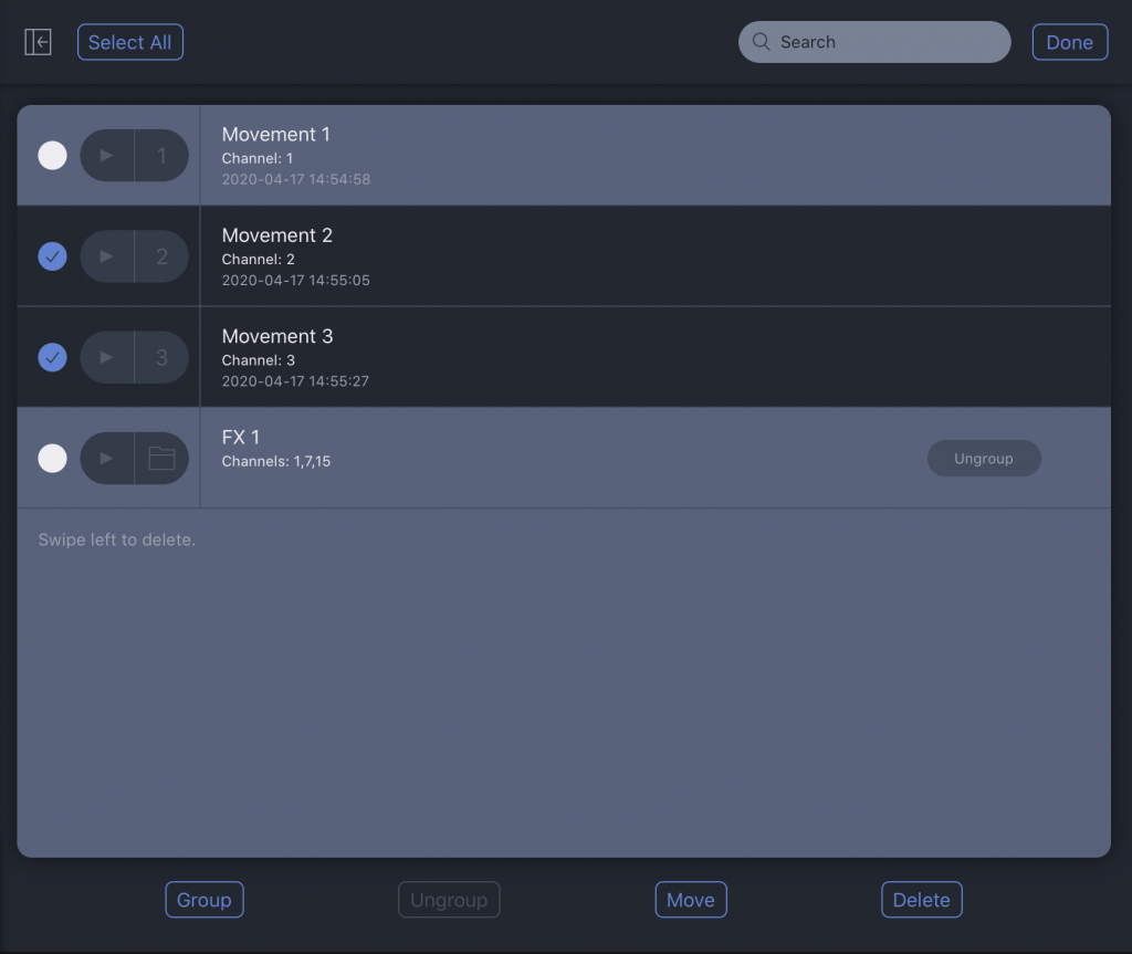
Setlist View – Group/Ungroup, Move, and Delete Channel Snapshots
To move/copy a Channel Snapshot to another Mix Snapshot, tap EDIT , select the channels to be moved, and tap MOVE. The popover that opens lists the possible destination Mix Snapshots.
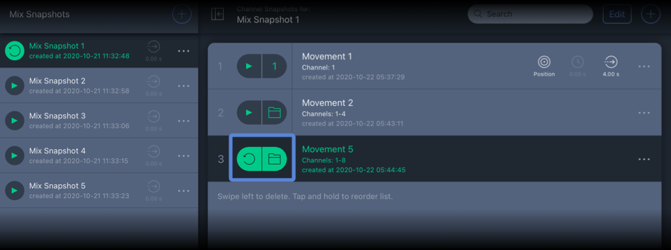
Setlist View – Channel Snapshot Group Indicated by Folder Icon
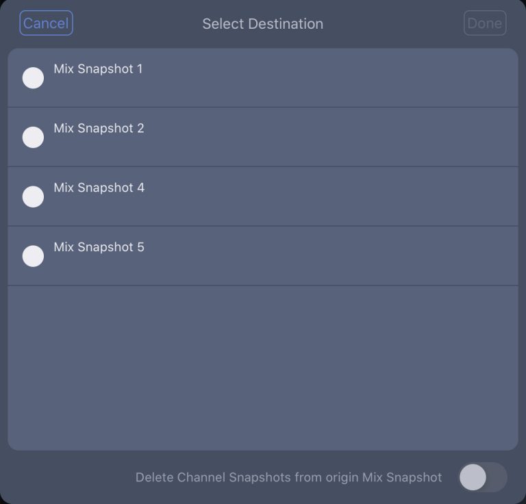
Mix Snapshot Selection
Delete mix or channel Snapshots
To delete a Mix or Channel Snapshot, swipe left on the Snapshot.
Important
This action cannot be undone. Channel Snapshots included in the Mix Snapshot are also deleted.
To delete many Channel Snapshots at the same time, tap EDIT , select the Channel Snapshots, and tap DELETE.
Create view
The Create View displays the Spacemap and Trajectory libraries. Tap the SPACEMAPS and TRAJECTORIES buttons at the top of the view to switch between the libraries.
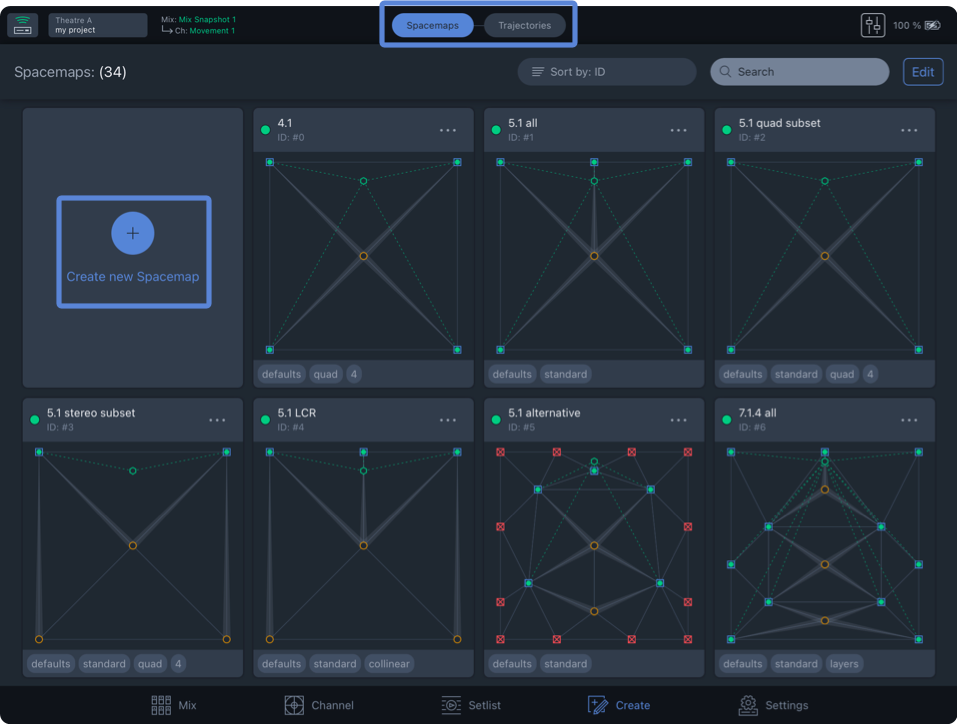
Create View – Spacemap Library
Create a new Spacemap
To create a Spacemap, select SPACEMAP at the top of the view and tap CREATE NEW SPACEMAP (above) to open the Spacemap editor.
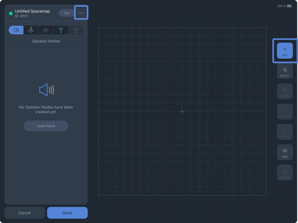
Tap the ADD button on the right (below). Select one of the four node types on the left, then tap inside the Spacemap to add nodes. Use two-finger pinch and open gestures to zoom the Spacemap.
Tap More (three-dot icon) next to the Spacemap name to edit the name, save a Spacemap file, and add tags.
Create View – Add Spacemap
Nodes types
For more information about nodes and their uses in a Spacemap, please see the Spacemaps page.
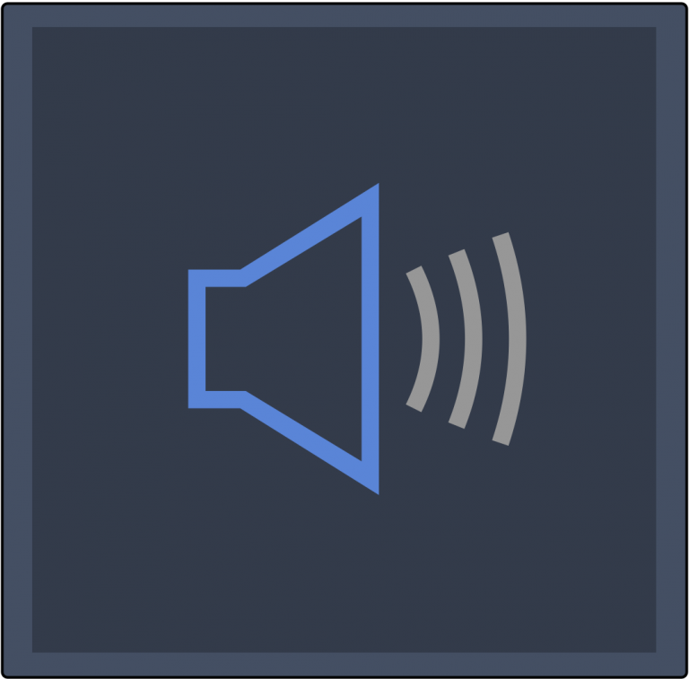 | Speaker Nodes Speaker Nodes represent the physical outputs of a Spacemap System as blue squares. Positions of Speaker Nodes in a Spacemap can represent the loudspeaker layout logically, randomly, or abstractly. Abstract layouts are usually used to facilitate specific panning scenarios that would be difficult or impossible to create with a logical speaker node layout. |
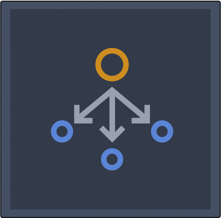 | Virtual Nodes Virtual Nodes simulate a physical output for panning purposes and can be used in conjunction with Silent Nodes. Virtual Nodes are linked to Speaker Nodes and/or Silent Nodes. The links are indicated graphically by a translucent line, wider at the Virtual Node, narrower at the linked Speaker Node. When the Spacemap Panner is moved to a Virtual Node, the input signal is equally distributed to the linked Speaker Nodes by default. Each linked Speaker Node has a Link Weight that is adjustable (0–100%). |
 | Silent Nodes Silent Nodes are included in Trisets, just like Speaker Nodes, but they are not associated with an output. When the Spacemap Panner is moved closer to a Silent Node, all output levels of the channel are reduced. When the Spacemap Panner is on a Silent Node, all output levels of the channel are -∞ (-infinity) dB. Moving the Panner closer or further away from a Silent Node is an easy way to fade-in or fade-out a channel using the Spacemap Panner instead of the channel level control. In a Spacemap, when the Spacemap Panner is moved to a location that does not include a Triset, all of the output levels of the channel drop to -∞ dB. As the Panner is moved on and off of Trisets it will sound like the mute for the channel is being toggled. If this is not the desired effect, Silent Nodes can be added at the extents of a Spacemap with Trisets that include them. When Trisets fill the entirety of a Spacemap and the Spacemap Panner approaches the edge of the Spacemap, the output levels will not suddenly drop to -∞ dB. Instead, the output levels are gradually reduced as the Panner is moved closer to a Silent Node. |
 | Derived Nodes Derived Nodes link to one or more Speaker Nodes and receive the sum of the signals from the linked Speaker nodes. They are represented as hexagons in a Spacemap. Dashed lines indicate the Speaker Nodes to which they are linked. Derived Nodes are used as a method to send input signal to additional outputs, relative to the linked Speaker Nodes. They are commonly used for subwoofer sends, fill mixes, sends to balconies, and other cases where a secondary mix-down of a multichannel mix is required. |
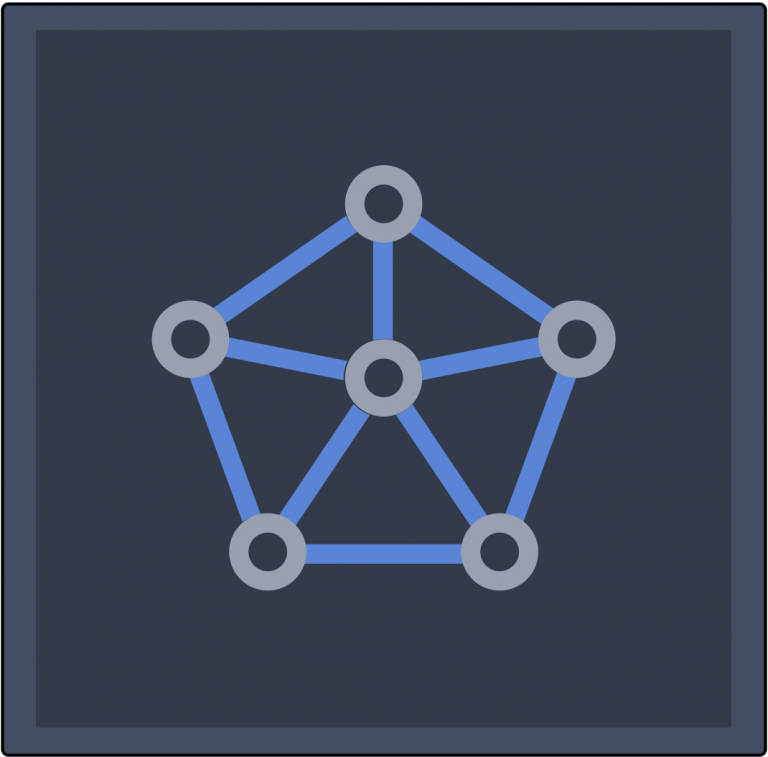 | Trisets At least one Triset is required in each Spacemap. Trisets are triangular panning surfaces created between three nodes that define the panning area between them. In conjunction with the relative location of the Spacemap Panner, Trisets are used by the app to determine the output levels for each node. The size of the Triset is not critical because the power-preserving panning law is proportional rather than absolute. The output levels are calculated based on the relative distance between the Spacemap Panner and each of the nodes that make up a Triset, rather than the actual physical distance within the grid of the Spacemap. If an area of a Spacemap does not have a Triset and the Spacemap Panner is moved there, the output levels will drop to -∞ dB (the input signal will not be sent to any output). Trisets can be generated automatically or added manually when creating or editing Spacemaps in Create View. 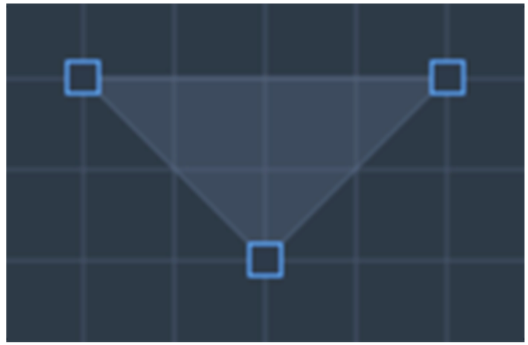 |
Toolbar
Tap the tools to the right of the canvas to add, select, or delete nodes in the Spacemap.
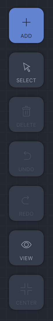 Toolbar | ADD: Tap in the Spacemap to add the selected node type. |
SELECT: Tap a Node or Triset to edit or move it. | |
DELETE: Tap to delete the selected Nodes or Trisets. | |
UNDO: Tap to undo the last change. | |
REDO: Tap to redo the last undo. | |
VIEW: Opens Spacemap view option popover for Spacemap (see below). | |
CENTER: Zoom to extents. |
View options
The View popover has several options that facilitate Spacemap creation:
SHOW SPACEMAP: A Spacemap can be selected as reference for node locations.
SHOW GRID: Toggles display of grid lines.
SNAP TO GRID: When enabled, nodes are only added at grid intersections.
BLOCK GRID SIZE: The grid size is adjusted in four increments.
SHOW CIRCULAR GUIDE: Overlays a circle with a number of snap points equally spaced. Use sliders to adjust size and number of points (Spacemap only).
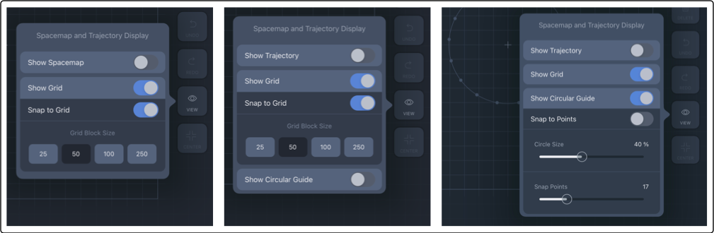
Create View, View Options – New Trajectory (left), New Spacemap (middle), New Spacemap with Show Circular Guide On (right)
Test Spacemap
Tap the TEST button next to the Spacemap name in the upper-left corner to open the Spacemap Test View.
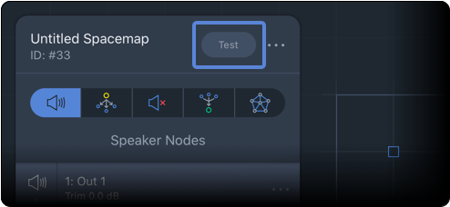
Create View – Spacemap Test Button
Move the Spacemap Panner, observe the output levels and confirm desired behavior.
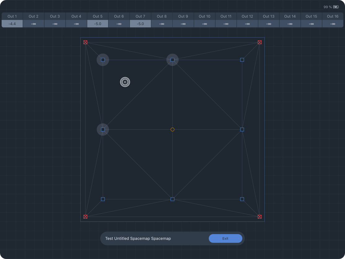
Create View – Spacemap Test Mode
Create a new Trajectory
To create a Trajectory, tap TRAJECTORY at the top of the Create View. Tap CREATE NEW TRAJECTORY to open the Trajectory editing controls. Tap START RECORDING and draw inside the Spacemap to create a path. Tap FINISH RECORDING to end. Use two-finger pinch and open gestures to zoom the Spacemap.
A trajectory is a series of points that can be edited. Tap TIME and POINTS to edit values. Two times are listed for each point. The first is the wait time, the second is the time between consecutive points. The total time can be edited—modifying the individual wait and next-point times proportionally.
Tap the three-dot icon next to the name in the upper-left to edit the name, save as a Trajectory file, and add tags.
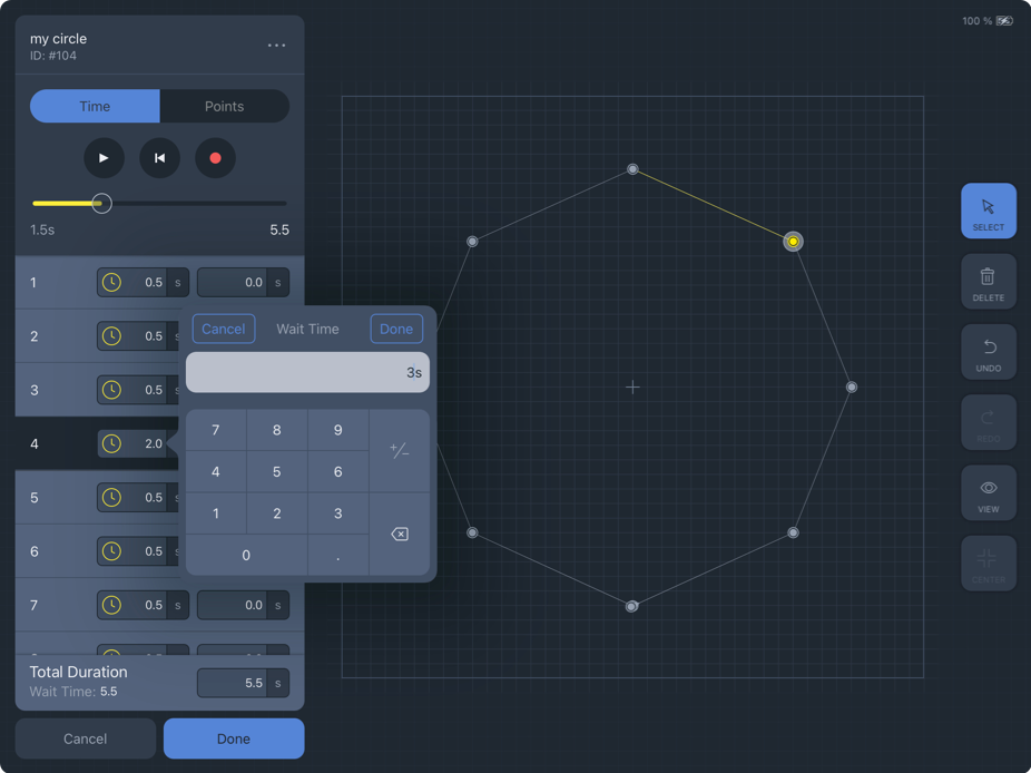
Create View, Trajectory Editor – Edit Wait Time for Point 4
Tap-hold and move a Trajectory Point to modify the trajectory shape. The POINTS option lists the X,Y coordinates (-1000 to 1000) for each point. Tap to edit values. Tap DONE to add the Trajectory to the library.
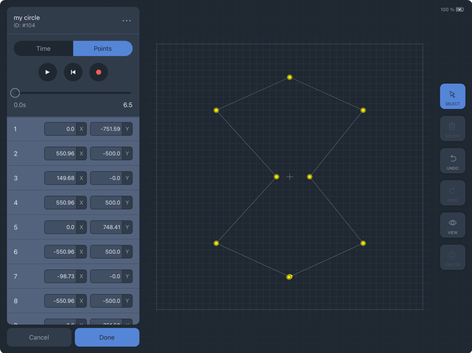
Create View – Edit Trajectory Points
Settings view
The Settings View includes System Settings and App Settings on the left side of the view.
Settings View – System and App Settings
System settings
System Settings includes controls and functions not related to mixing or appearance. Tap the buttons on the left to reveal the associated details and settings.
Galaxy processor status
Tap the name of a Spacemap System to display details about each connected GALAXY processor.
Three colors differentiate the state of each processor (below).
GREEN: The processor is online and operating normally.
YELLOW: Indicates the module is connected but is not part of a Spacemap System.
RED: Indicates the processor is defined as part of a system but is not connected.
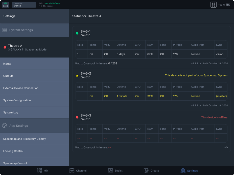
Settings View – System Status, Reported Processor States