Clocking
Media clock for a single GALAXY processor
Note
Media clock is the common terminology used in the Milan specification. Within the GALAXY processor settings: Input and Output tab, the media clock choice is selected under the System Clock: Clock Mode pull-down menu.
The GALAXY 816 processor and the GALAXY 408 processor offer four clock options for the media clock: GALAXY internal clock, CRF clock stream, AAF audio stream clock, and AES3 clock (the first four choices shown in the figure below, GALAXY System Clock Selection box).
The GALAXY 816-AES3 processor offers the same four plus a Word Clock of 48 or 96 kHz via an additional BNC connector.The GALAXY 816-AES3 processor can be synchronized to an external source depending on the digital input selection: AES3 offers discrete values in the range from 20–216 kHz (see Input sample rates).
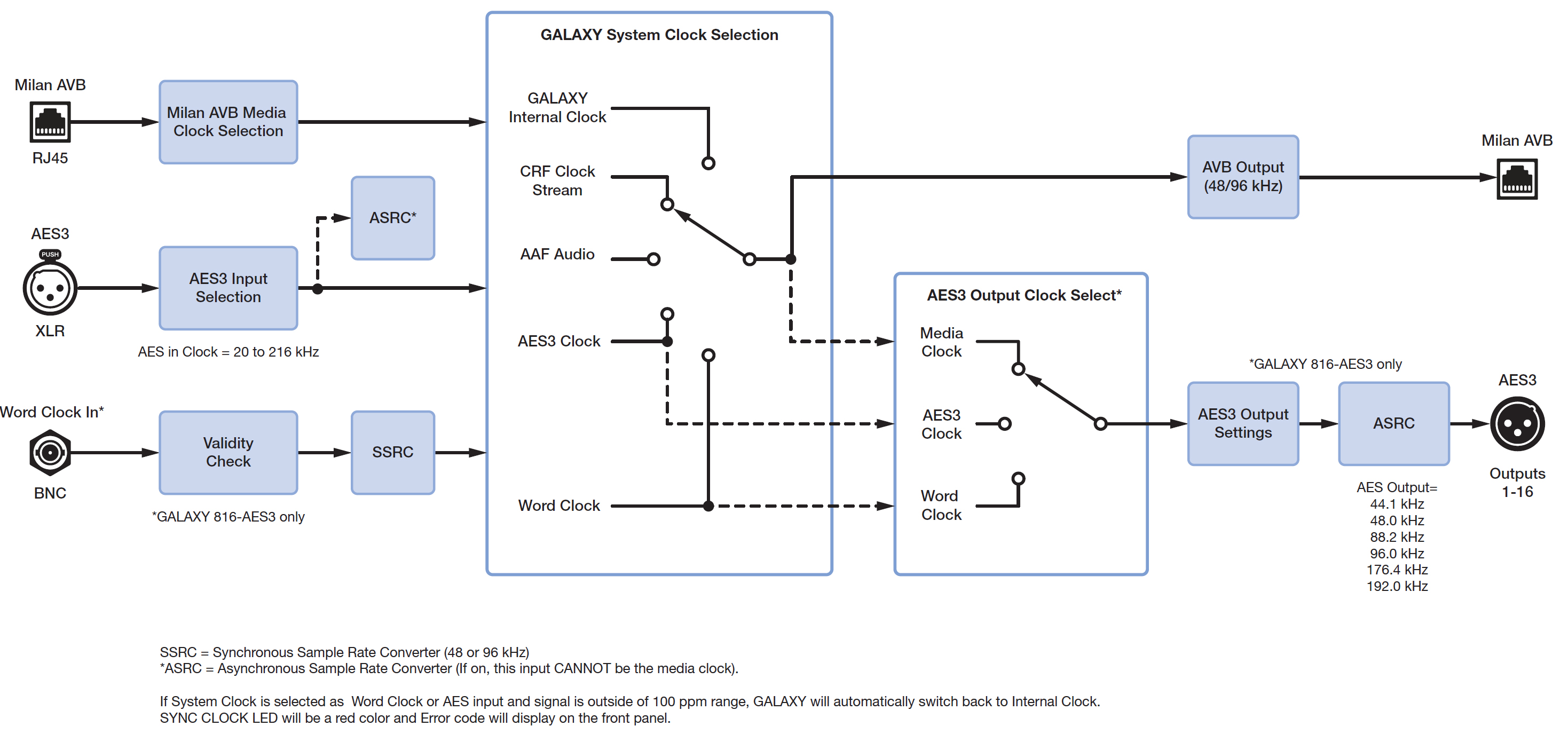
GALAXY processor clocking scheme
Note
For an AES3 input to be selectable in the System Clock, Clock Mode drop-down, it must be synchronous to the GALAXY internal clock (48 kHz or 96 kHz ±100 ppm). Synchronous means the external source and the GALAXY processor have a common clock (to within ±100 ppm). A common clock with the sender of data is necessary for any device to accurately interpret the binary data it receives. If the device clocks are asynchronous—any of the allowable AES input clock rates NOT equal to 48 kHz or 96 kHz, and thus not common with the GALAXY internal clock—they cannot be used as a system clock. Furthermore, any audio input associated with this asynchronous clock must pass through the Asynchronous Sample Rate Converter (ASRC) to make that input data synchronous, or accurately aligned to the GALAXY processor's internal processing clock.
Common media clock for multiple interconnected GALAXY processors
When connecting multiple GALAXY processors, one common media clock must be used. Clocks should never be daisy-chained. Even small timing differences can cause audible audio degradation. The three figures below illustrate common multiple GALAXY processor clocking configurations for networked GALAXY processors. They do not cover all possible clocking schemes.
For more information about networking schemes in general, see the AVB Networking Guide.
The first figure below illustrates an example where an analog or asynchronous AES3 input must be sent through several GALAXY processors. While an audio signal may be daisy-chained from one GALAXY processor to the next, it is worth repeating that the clock must never be daisy-chained. In the case illustrated in the first figure below, GALAXY 1 receives an analog or asynchronous AES3 input, and its system clock should be set to Internal to use the device clock. For an AES3 Asynchronous signal, the asynchronous AES3 Sample Rate Converters (ASRC) must be enabled for that input.
Subsequent processors (in this case GALAXY processors 2, 3, 4 and 5) must receive their system clock from the same source (GALAXY 1), which can be accomplished by using the CRF clock (Clock Reference Format packets) from GALAXY 1.
Note
An AAF clock may also be sent from GALAXY 1 as a media clock, but the CRF clock is preferable as it is more bandwidth efficient.
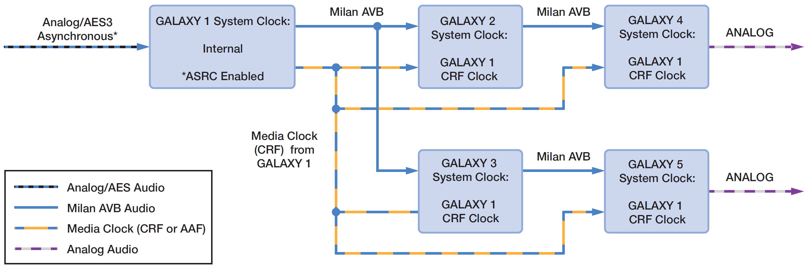
Clocking scheme for multiple GALAXY processors — analog or AES3 asynchronous inputs
The figure below illustrates an example where an AES3 signal aligned to a word clock must be sent through several GALAXY processors. Again, the clock cannot be daisy-chained along with the audio signal. In this case, if GALAXY A (which must be a GALAXY 816-AES3 processor) receives an AES3 input synchronized at its source to a word clock, its system clock should be set to the word clock received from the same source via the BNC connector. In this case, the AES ASRC must be disabled.
Subsequent processors (GALAXY processors B, C, D and E, which can be any GALAXY processor model) must receive their system clock from the same source (GALAXY A). Use the CRF clock (Clock Reference Format packets) from GALAXY A as the system clock mode selection. The AES ASRC for succeeding GALAXY processors (B, C, D, and E) must also be disabled.
Note
An AAF clock may also be sent from GALAXY A as a media clock, but the CRF clock is preferable as it is more bandwidth efficient.
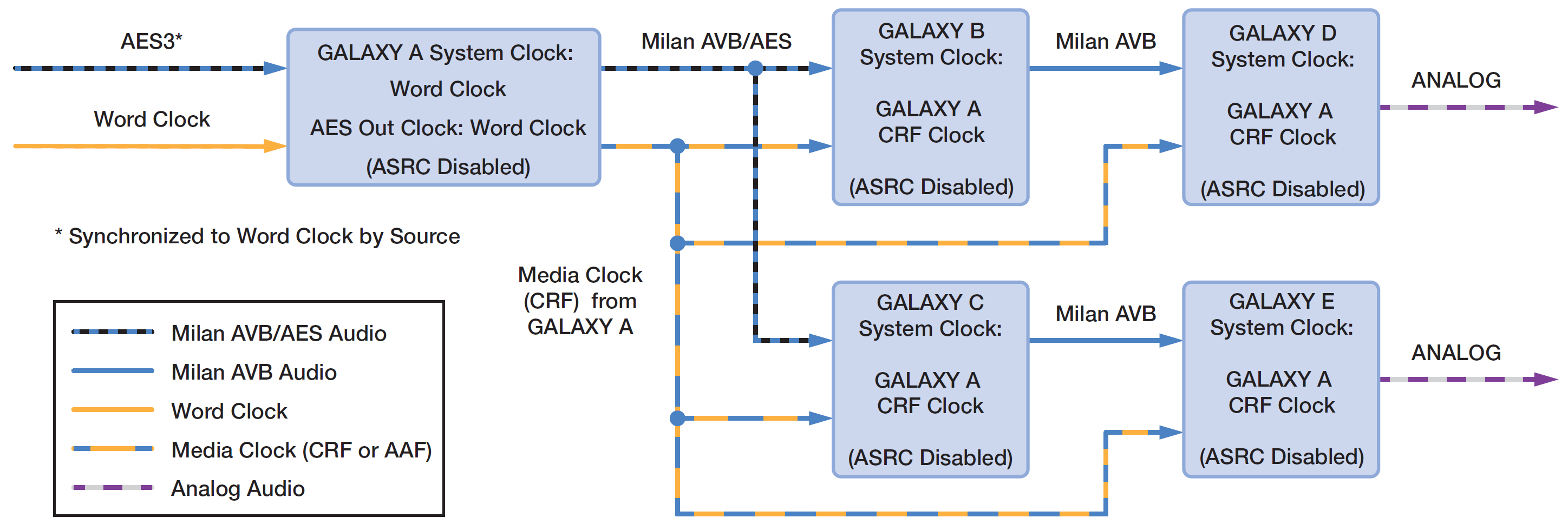
Clocking scheme for multiple GALAXY processors—AES3 input with word clock
The figure below illustrates an example where an AVB signal coming into the first GALAXY processor must be sent through several GALAXY processors. Again, the clock cannot be daisy-chained along with the audio signal. In this case, the source of the AVB signal must also provide the media clock, because GALAXY 1 would add latency, as it is essentially daisy-chained itself from the input source. In this case, all GALAXY processors (1–5) can receive the same media clock by dedicating 1 of the available 32 AVB channels to act as a system clock. Select the system clock mode to be any of the AAF audio streams.
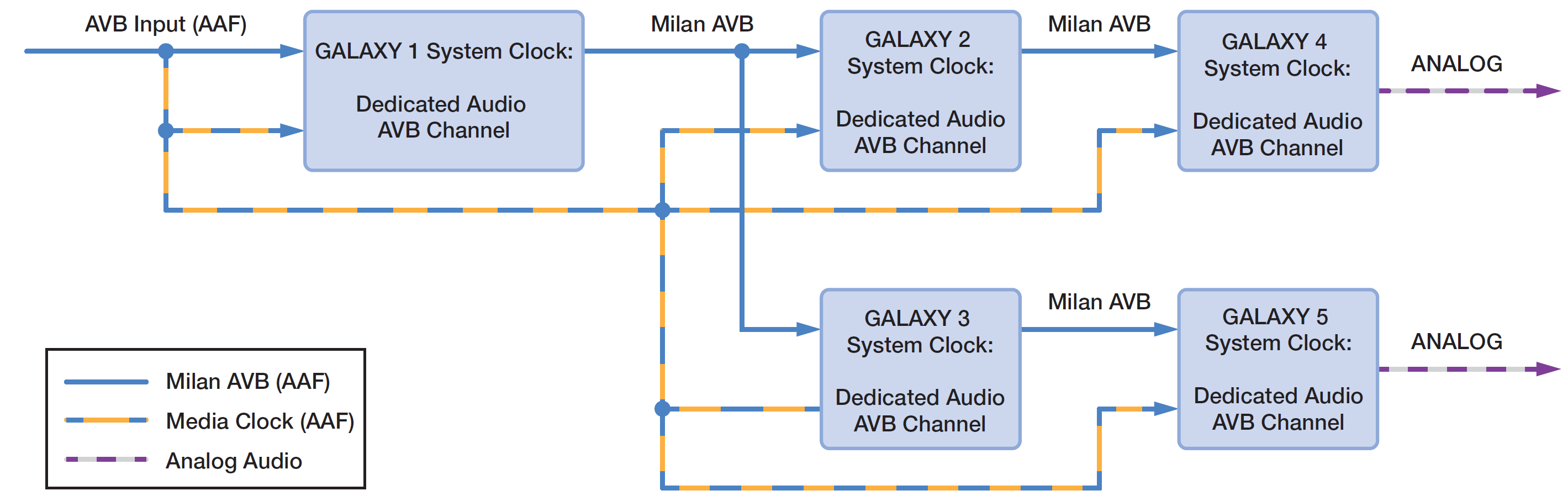
Clocking scheme for multiple GALAXY processors—AVB input source
Digital latency
GALAXY processors feature fixed latency across all output channels, regardless of the processing applied. The analog latency for GALAXY processors (AD/DA) is fixed at 0.5968 milliseconds. GALAXY processor AES3 inputs have sample rate converters that support a range of sample rates. Changing the sample rate can increase the latency to approximately four times this value, depending on the sample rate selected.
Note
While each GALAXY processor has fixed latency, overall system latency from a local GALAXY processor’s (talker) physical analog outputs and any remote GALAXY processors’ (listeners) physical analog outputs can vary. To ensure proper alignment, measure the delay between the local GALAXY processor’s physical analog outputs to any remote GALAXY processor(s) physical analog outputs using an accurate audio analyzer (such as Meyer Sound’s SIM System).
Input sample rates
With the ASRC enabled, the GALAXY processor can accept a range of sample rates for AES inputs, as shown in the table below. To use AVB inputs, a common clock must be selected.
Table 4: Accepted Input sample rates and bit depth based on format
Format | Input sample rates accepted (kHz) | Bit depth |
|---|---|---|
AES3 | 20 – 216 | up to 24 bit |
AVB | 48 or 96 | 24 bits in 32 bit integer |
AES3 output sample rates
If an AES3 or word clock input is selected as the AES output clock source (GALAXY 816-AES3 processor only), then the following sample rates may be used:
44.1 kHz
48.0 kHz
88.2 kHz
96.0 kHz
176.4 kHz
192.0 kHz