PANTHER Rigging
PANTHER Rigging Accessories
The available rigging accessories and PANTHER loudspeakers are listed in the table below.
Model | Weight | Features | Required Quick-Release Pins | Required Shackles |
|---|---|---|---|---|
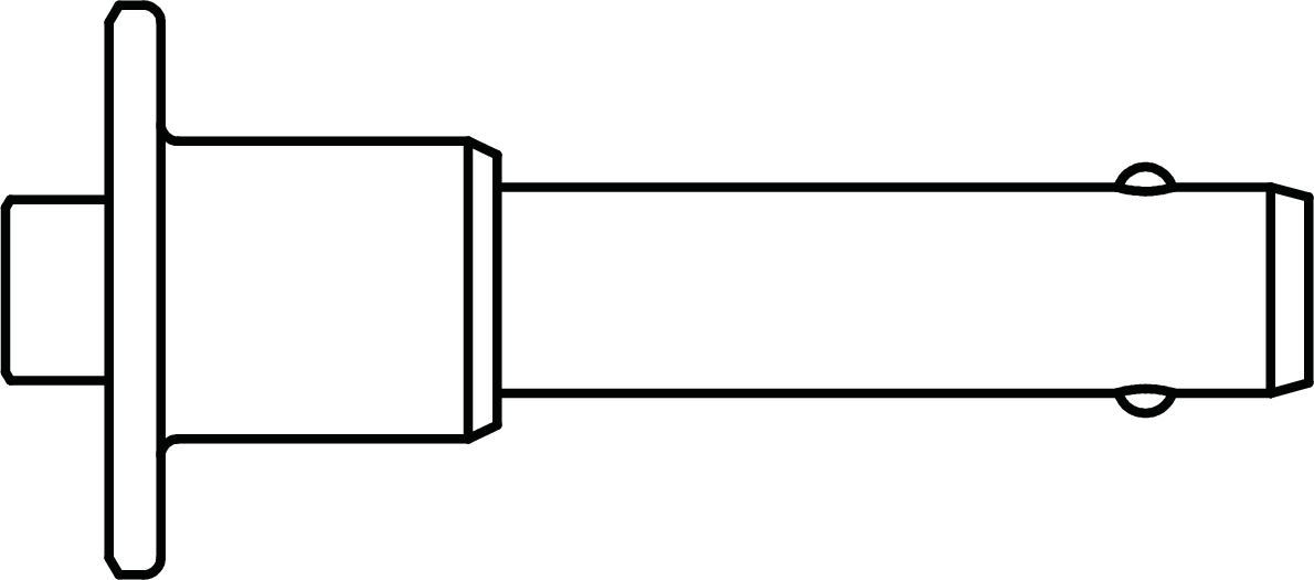
PANTHER Loudspeaker | 150 lb (68 kg) | Includes end-frames and GuideALinks secured with custom quick-release pins (QRP) for connections to other cabinets and rigging accessories. | 7/16 x 0.9-inch QRP (black button) with lanyard PN 134.065 qty 10 included | (none required) |
MVP Motor V Plate (PN 40.215.184.01) | 20 lb (9.1 kg) | Fine tunes the horizontal aim of arrays; compatible with other Meyer Sound products. | 3/4-inch or 7/8- inch | |
MG-PANTHER Grid Kit (PN 40.324.400.01) | 210 lb (95.3 kg) | With some restrictions, can support up to 25 PANTHER loudspeakers at a 5:1 safety factor. Kit includes MG-PANTHER Grid Box (PN 45.324.400.01) and MG-PANTHER Shackle Bar (PN 45.324.405.01). | 1/2 x 1.5-inch QRP (red button) with lanyard PN 134.045 qty 4 included and 7/16 x 1.5-inch QRP (red button) with lanyard PN 134.051 qty 4 included | 3/4-inch or 7/8- inch |
PBF-LYON Pull-Back Frame (PN 40.232.125.01) | 9.5 lb (4.3 kg) | Attaches to the bottom cabinet of PANTHER arrays and provides pull-back for extreme array downtilt; can also be used for pull-up to expand the array’s splay angles during installation so the LOCK pins can be more easily inserted. | This accessory is secured with the quick-release pins included with each PANTHER cabinet. | 5/8-inch |
MCF-PANTHER Caster Frame (PN 40.324.200.01) | 105 lb (68 kg) | Safely transports up to four PANTHER cabinets and the MG-PANTHER Grid Box (without the Shackle Bar) allowing assembly and disassembly of arrays in blocks of four cabinets. | This accessory is secured with the quick-release pins included with each PANTHER cabinet. | (none required) |
MTF-LYON/LEOPARD Transition Frame Kit (PN 40.232.140.01) | 71 lbs (32.2 kg) | Attaches to the bottom cabinet of PANTHER arrays to add LEOPARD loudspeakers below. With some restrictions, up to 10 LEOPARD at a 5:1 safety factor. | 5/16 x .0875-inch QRP (red button) with lanyard PN 134.025 qty 8 included | (none required) |
Note
The MCF-PANTHER Caster Frame and PBF-LYON Pull-Back Frame do not include quick-release pins. These accessories are secured with the quick-release pins included with each PANTHER cabinet.
Caution
Always model each array configuration in Meyer Sound’s MAPP System Design and Prediction software to determine if the array configuration is within safety limits (5:1 safety factor). Do not suspend an array when the Safety Limits Analysis in MAPP displays “Configuration has exceeded the rated load capacity.”
The PANTHER QuickFly rigging system includes custom quick-release pins. When assembling a PANTHER array, use only quick-release pins acquired from Meyer Sound to secure the connecting hardware (GuideALinks) and rigging accessories.
MVP Motor V Plate
The optional MVP Motor V Plate can be used to adjust the horizontal aim of PANTHER arrays up to ±18°.
MVP Motor V Plate Kit Contents
Quantity | Part Number | |
|---|---|---|
 | 1 | 45.215.184.01 |
The MVP Motor V Plate has the following load ratings:
5:1 | |
|---|---|
Maximum Number of PANTHER Loudspeakers + MG-PANTHER Grid Kit | 25 |
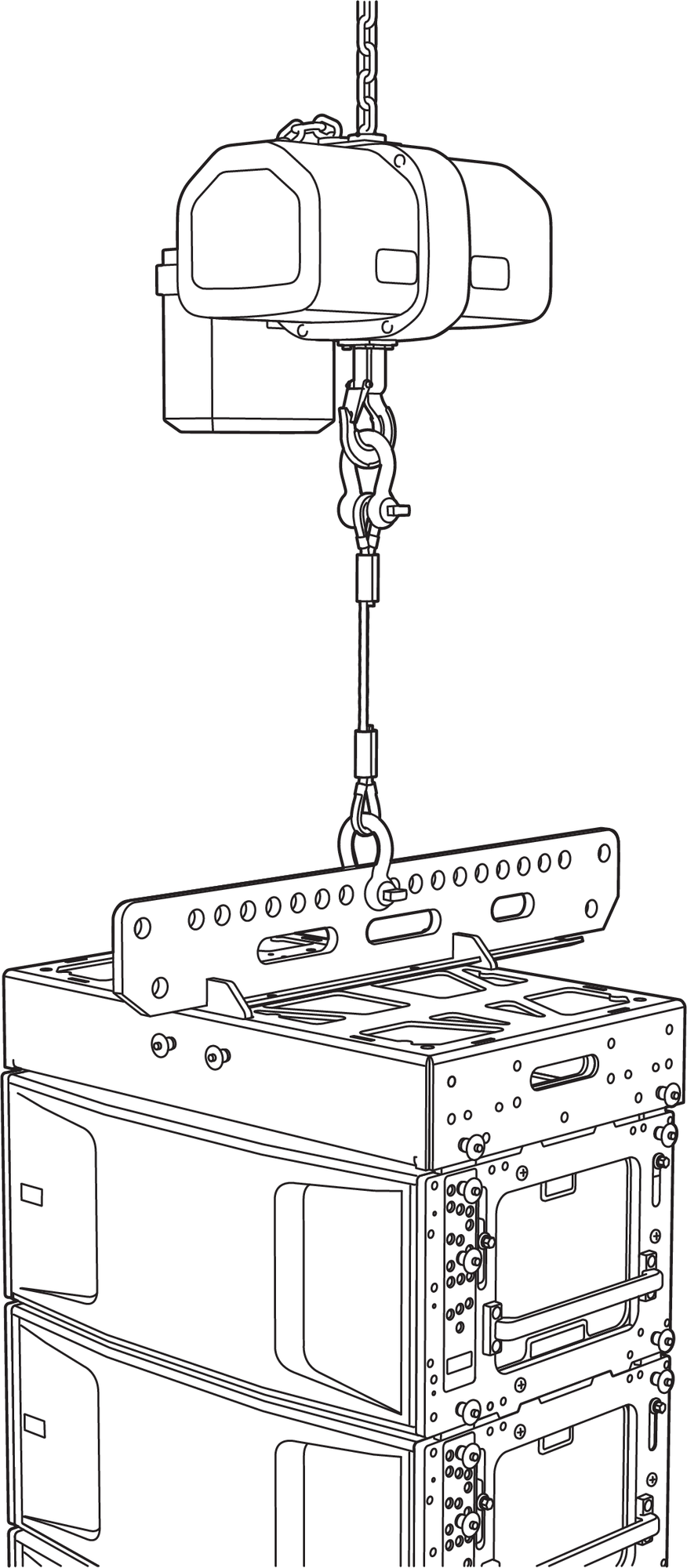
MVP Motor V Plate Overview
The top of the MVP Motor V Plate is connected to two hoists. The bottom of the MVP Motor V Plate connects to the MG-PANTHER Shackle Bar front or rear points (1 or 19).
 |
MVP-Motor V Plate, MG-PANTHER Grid Kit, PANTHER Loudspeakers
When the hoists are adjusted, the horizontal aim of the array is changed.
MVP-Motor V Plate, Pulling Up on Either Motor Rotates the Array
Caution
When assembling, disassembling, raising or lowering an array, always equalize the loading of the hoists connected to the MVP Motor V Plate. When the array is at the desired height and the grid has been tilted to the desired angle, adjust the hoists connected to the MVP Motor V Plate to achieve the desired horizontal rotation.
Always use sufficiently rated rigging hardware, e.g., wire rope, shackles, hoists, etc. for connections above and below the MVP Motor V Plate.
The two inner, top holes of the MVP Motor V Plate are not used for hoist attachment. These provide structural support for the front and rear plates of the accessory.
Note
The MVP Motor V Plate requires 3/4-inch or 7/8-inch shackles for its attachment points.
See Assembling Arrays and Disassembling Arrays for instructions.
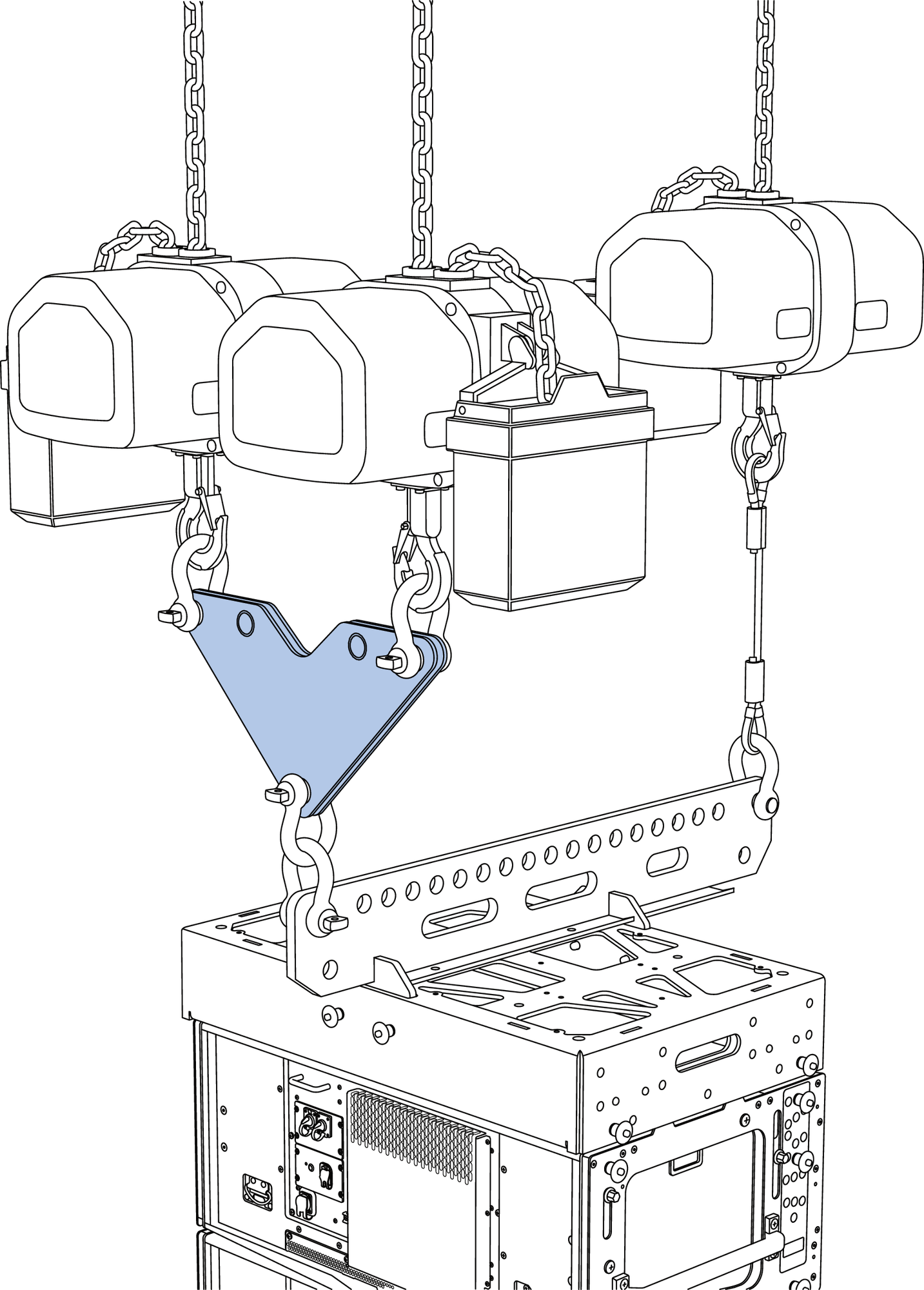
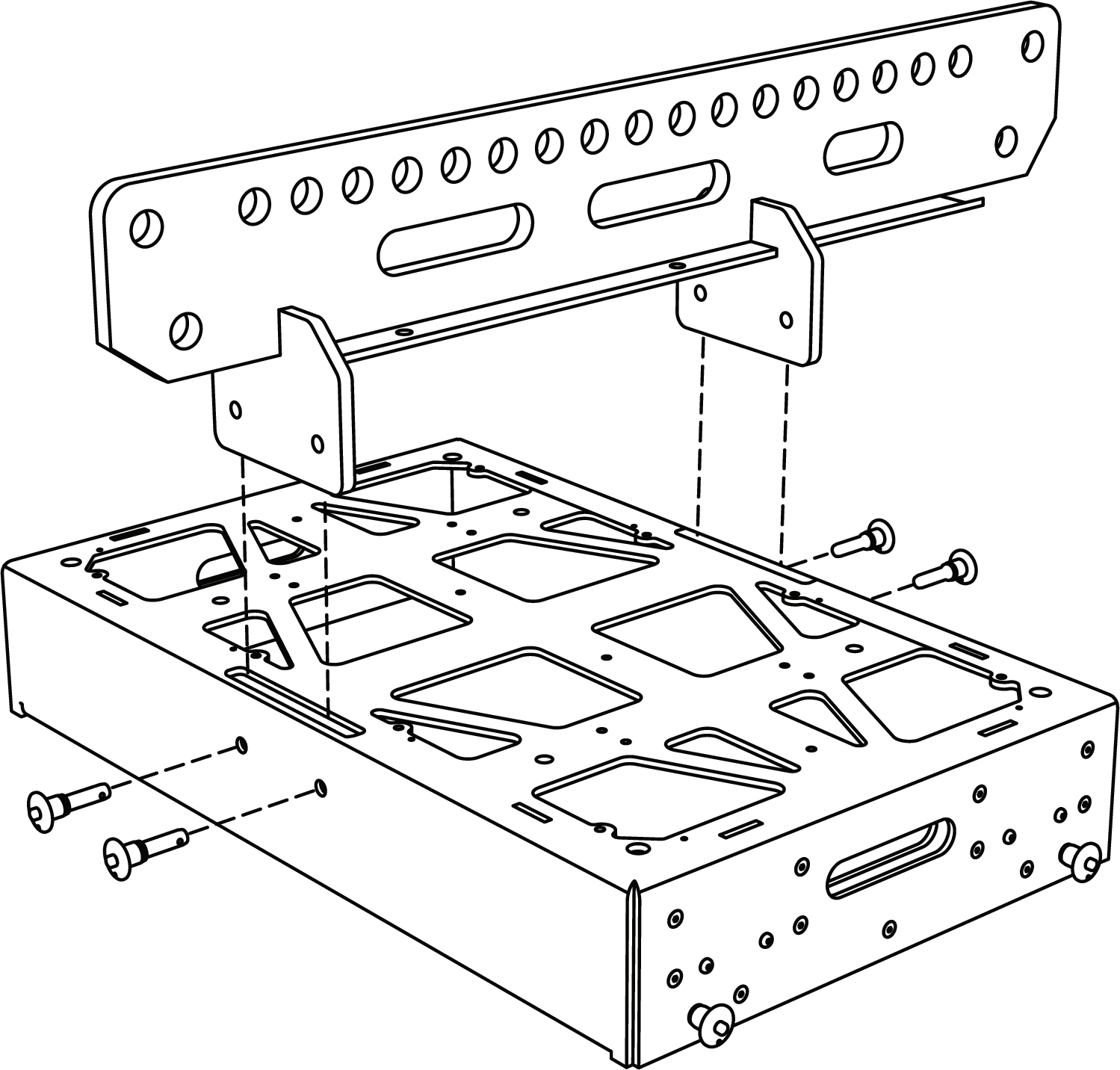
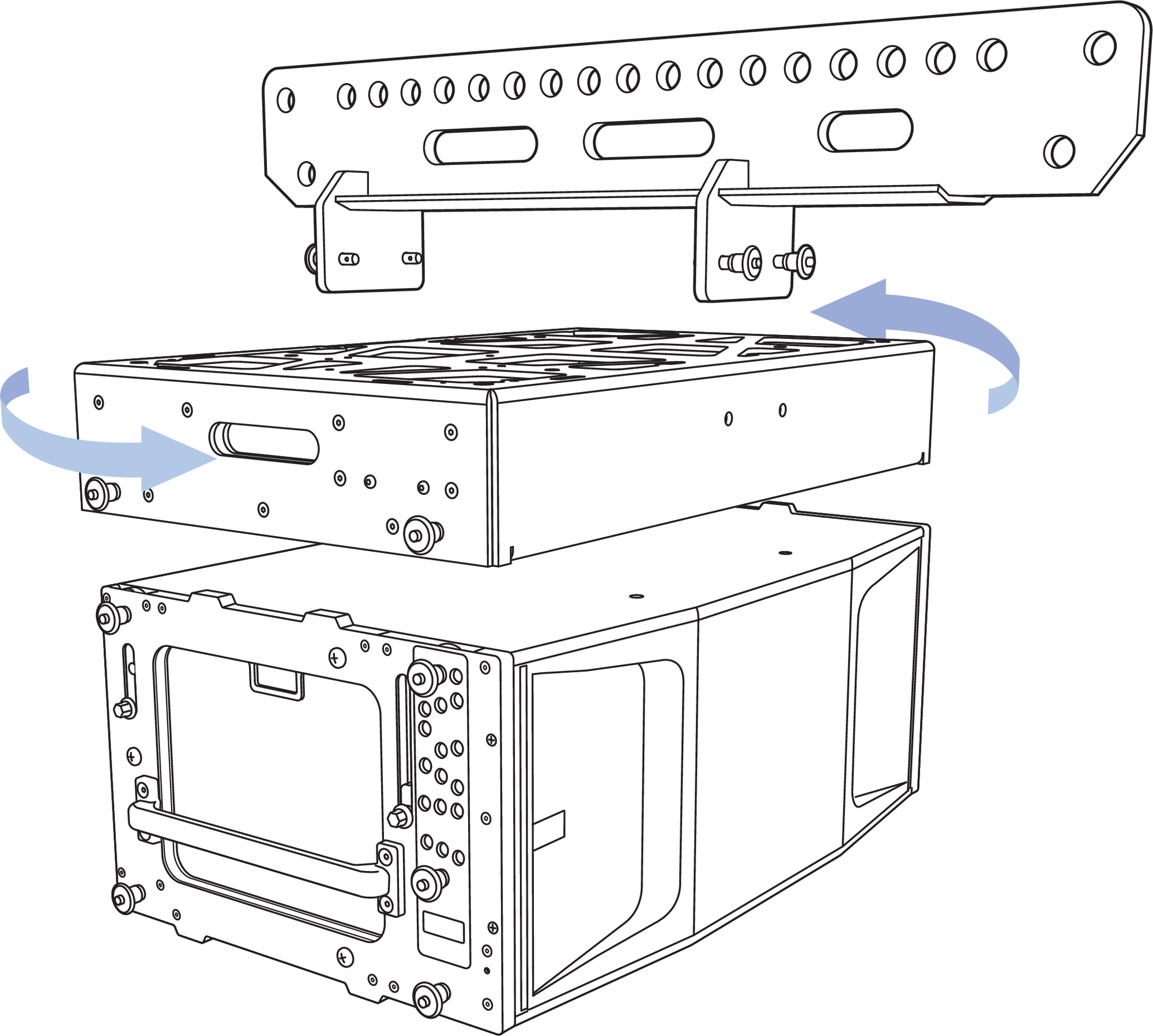
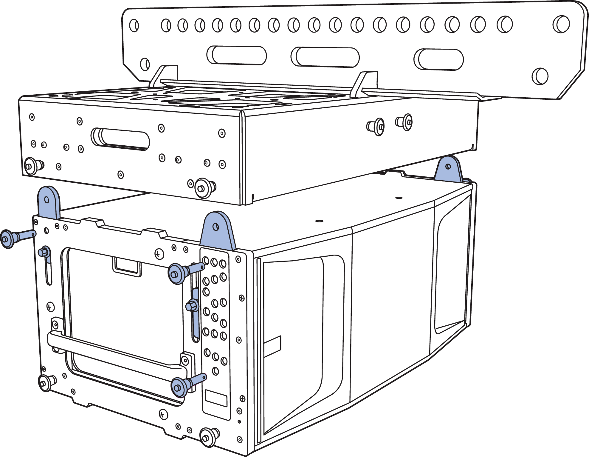
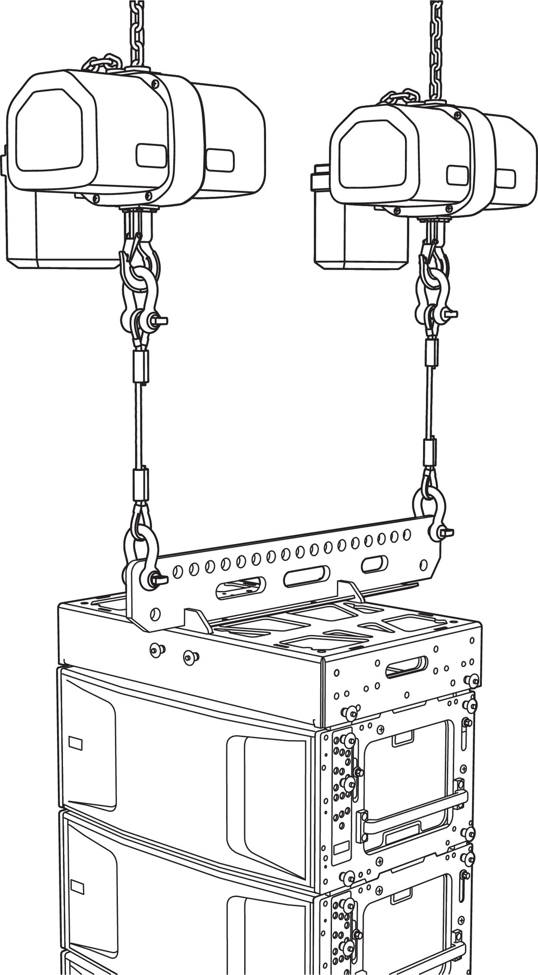
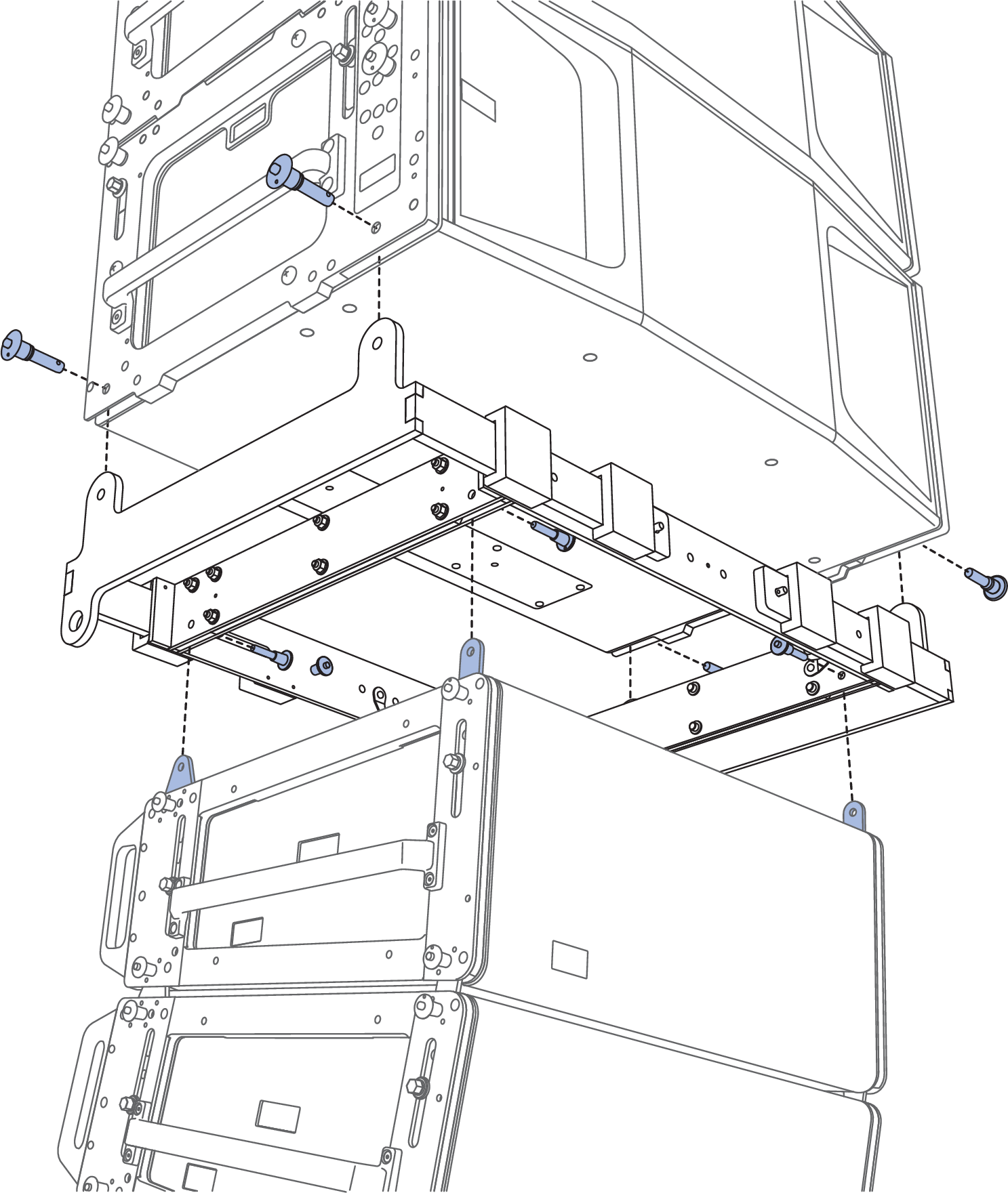
MG-PANTHER Grid Kit
The MG-PANTHER Grid Kit provides mechanical connection between hoisting mechanism(s) and PANTHER cabinets.
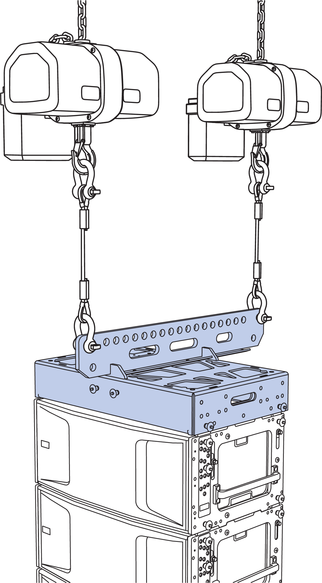
Hoists, MG-PANTHER Grid Kit, and PANTHER Cabinets
MG-PANTHER Grid Kit Contents
Image | Qty | Part Number | Description |
|---|---|---|---|
 | 1 | 45.324.400.01 | MG-PANTHER Grid Box |
 | 1 | 45.324.405.01 | MG-PANTHER Shackle Bar |
 | 4 | 134.045 | 1/2 x 1.5-inch QRP with lanyard (red button) |
 | 4 | 134.051 | 7/16 x 1.5-inch QRP with lanyard (red button) |
Description | Weight |
|---|---|
MG-PANTHER Shackle Bar | 72 lb (37.7 kg) |
MG-PANTHER Grid Box | 138 lb (62.6 kg) |
Table 5. MG-PANTHER Weights
Caution
Ensure the quick-release pins are fully inserted and locked during array assembly.
Always use the 1/2 x 1.50-inch QRP (red button, PN 134.045) included with the MG-PANTHER Grid Box to secure the MG-PANTHER Shackle Bar to the MG-PANTHER Grid Box.
Always use the 7/16 x 1.50-inch QRP (red button, PN 134.051) pins included with the MG-PANTHER Grid Box to secure the MG-PANTHER Grid Box to the top PANTHER loudspeaker. Do not use the quick-release pins included with PANTHER loudspeaker as they are shorter and will not lock in place.
Always use properly rated rigging hardware, e.g., wire rope, shackles, hoists, etc. The MG-PANTHER Shackle Bar requires 3/4-inch or 7/8-inch shackles for its pickup points.
Do not transport 4-high stacks of PANTHER with the MG-PANTHER Shackle Bar attached to the MG-PANTHER Grid Box. This exceeds the safety limits for tip-over, which may cause injury.
Tip
When transporting 4-high stacks of PANTHER on MCF-PANTHER caster frames, the MG-PANTHER Grid Box can remain on top.
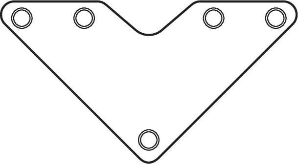
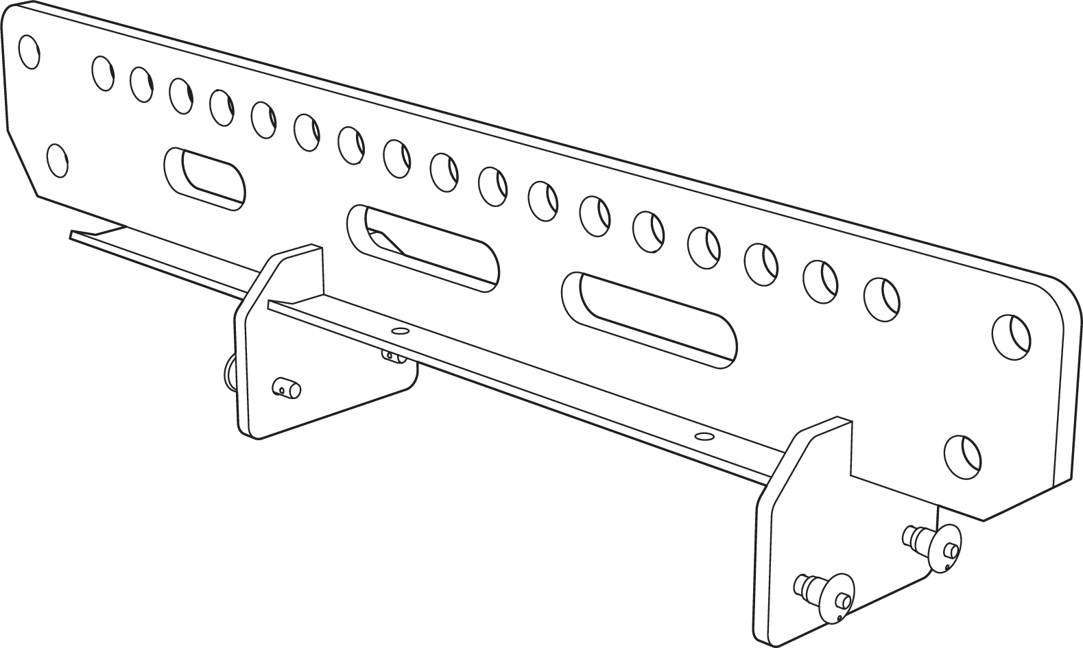
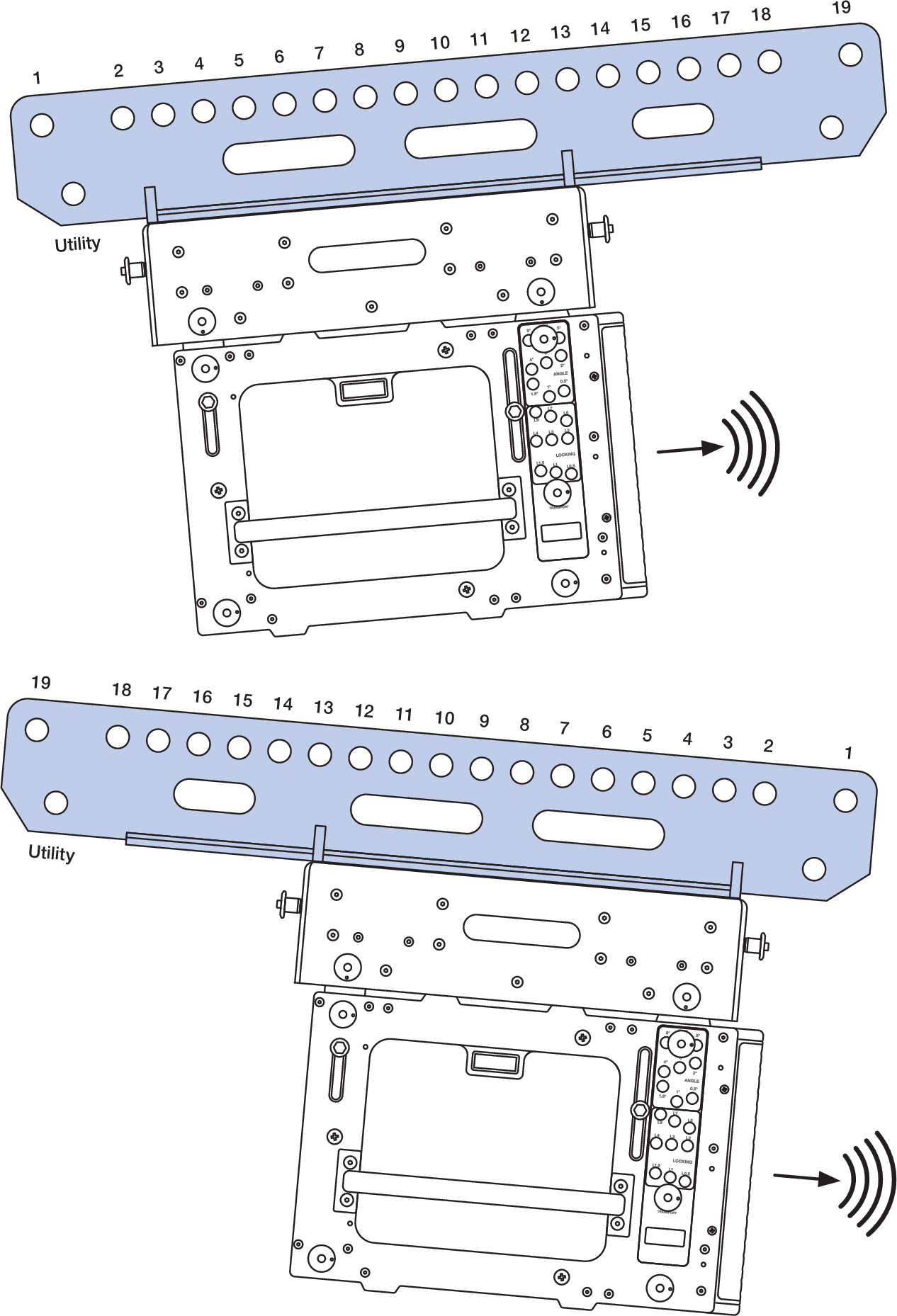
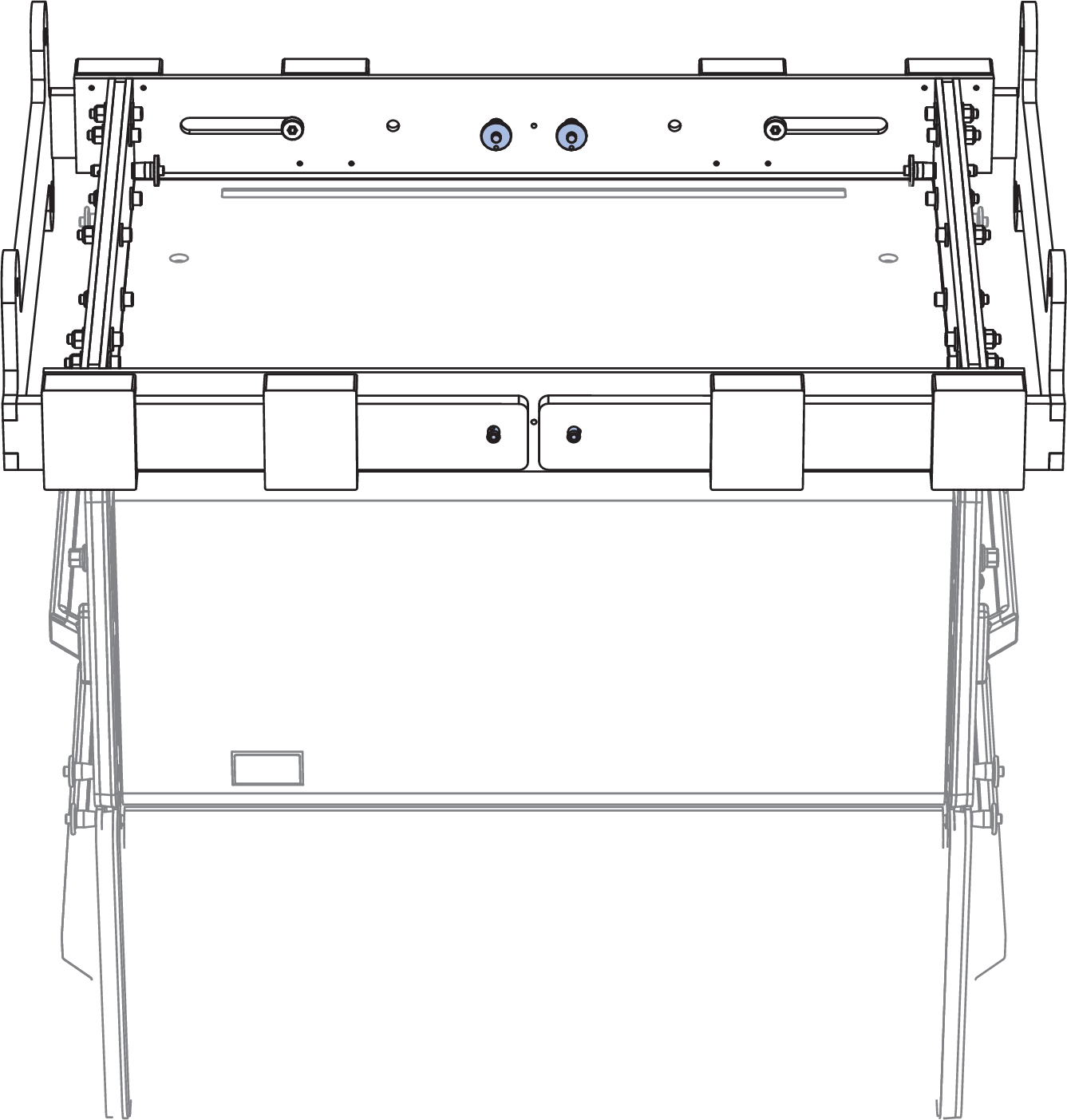
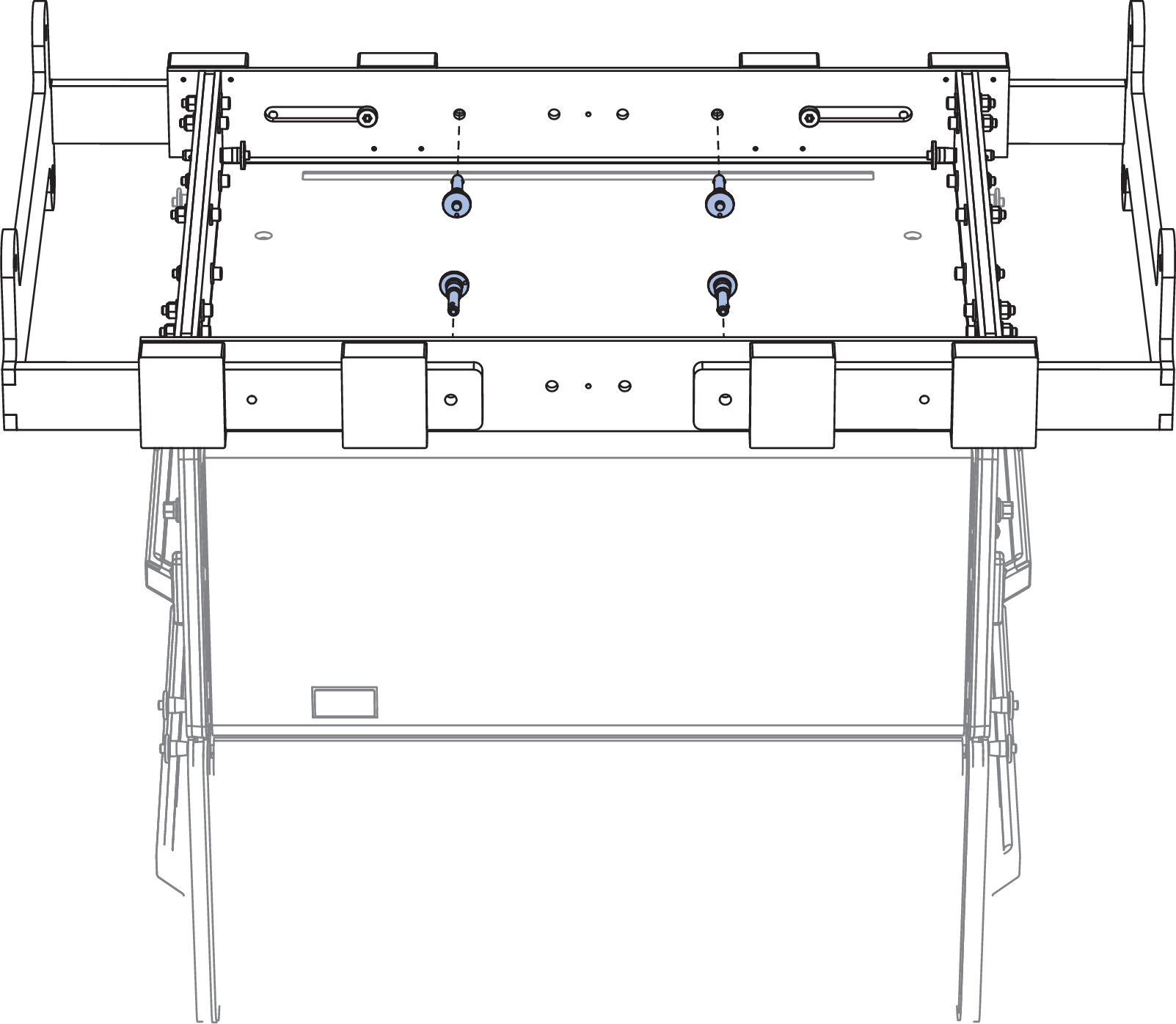
MG-PANTHER Shackle Bar
The MG-PANTHER Shackle Bar is attached to the MG-PANTHER Grid Box with four 1/2 x 1.50-inch QRP (red button, PN 134.045) pins that are secured to the MG-PANTHER Grid Box with lanyards. These quick-release pins are not interchangeable with any other pins used with a PANTHER array.
MG-PANTHER Grid Kit, Not Assembled
The top row of holes labeled 1 through 19 in Figure 21 below, are provided for connection to hoists. Use holes 1 and 19 when connecting two hoists. Two utility connection points (one at each end) are provided to connect cable picks and/or the chain of the pull-up mechanism (see PBF-LYON).
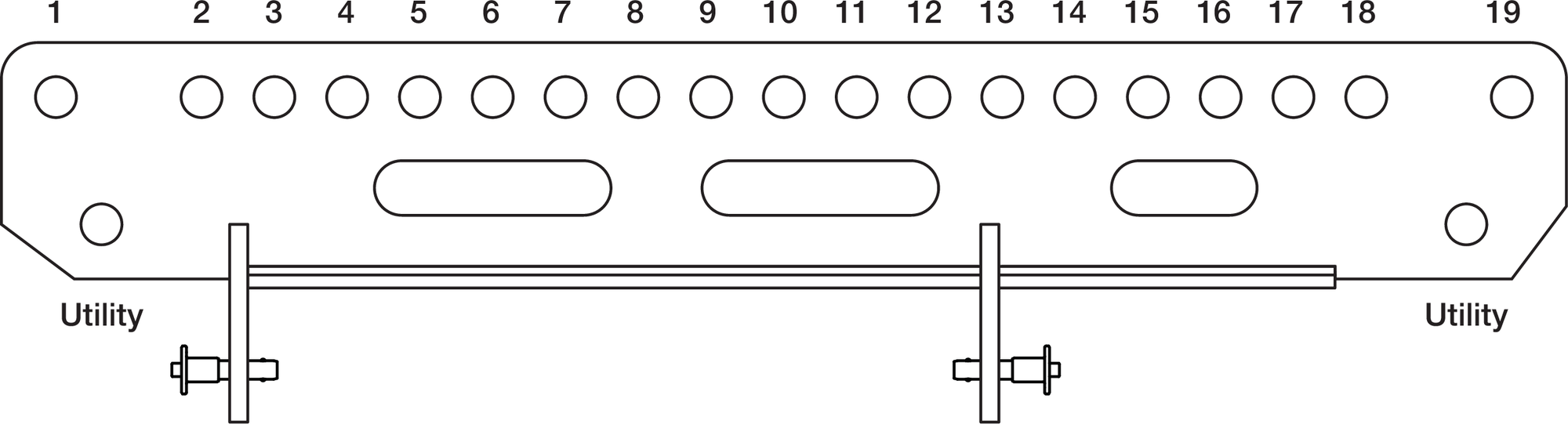
MG-PANTHER Shackle Bar
Caution
The points labeled “Utility” are never used to suspend an array
Tip
It may be convenient to store and transport both the MG-PANTHER Shackle Bar and PBF-LYON in a cable trunk that includes the cabling for an array.
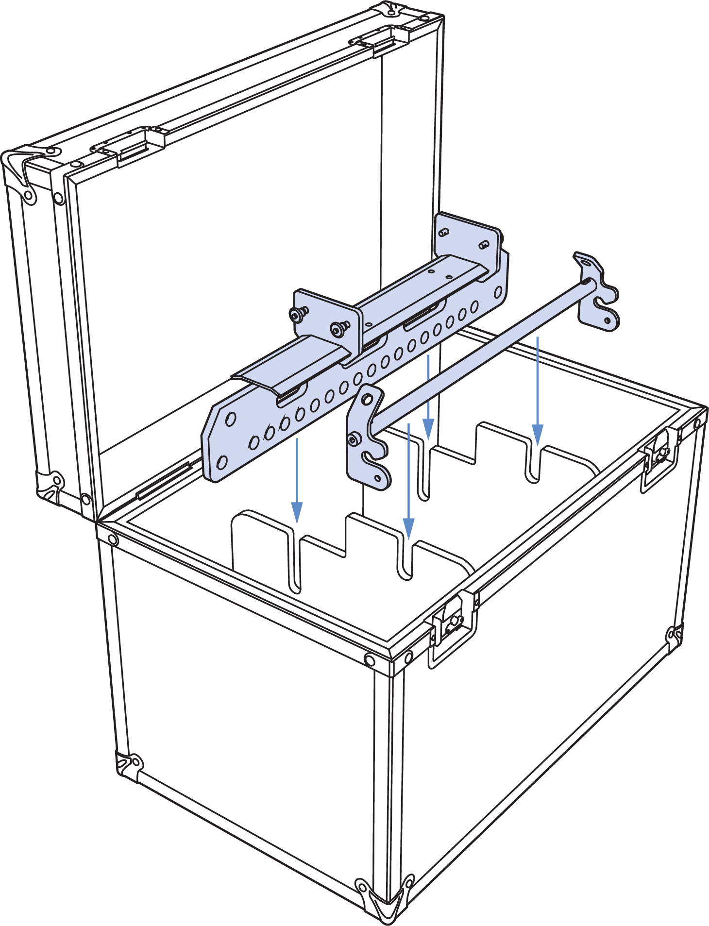
Cable Trunk Example for Accessory Storage and Transportation
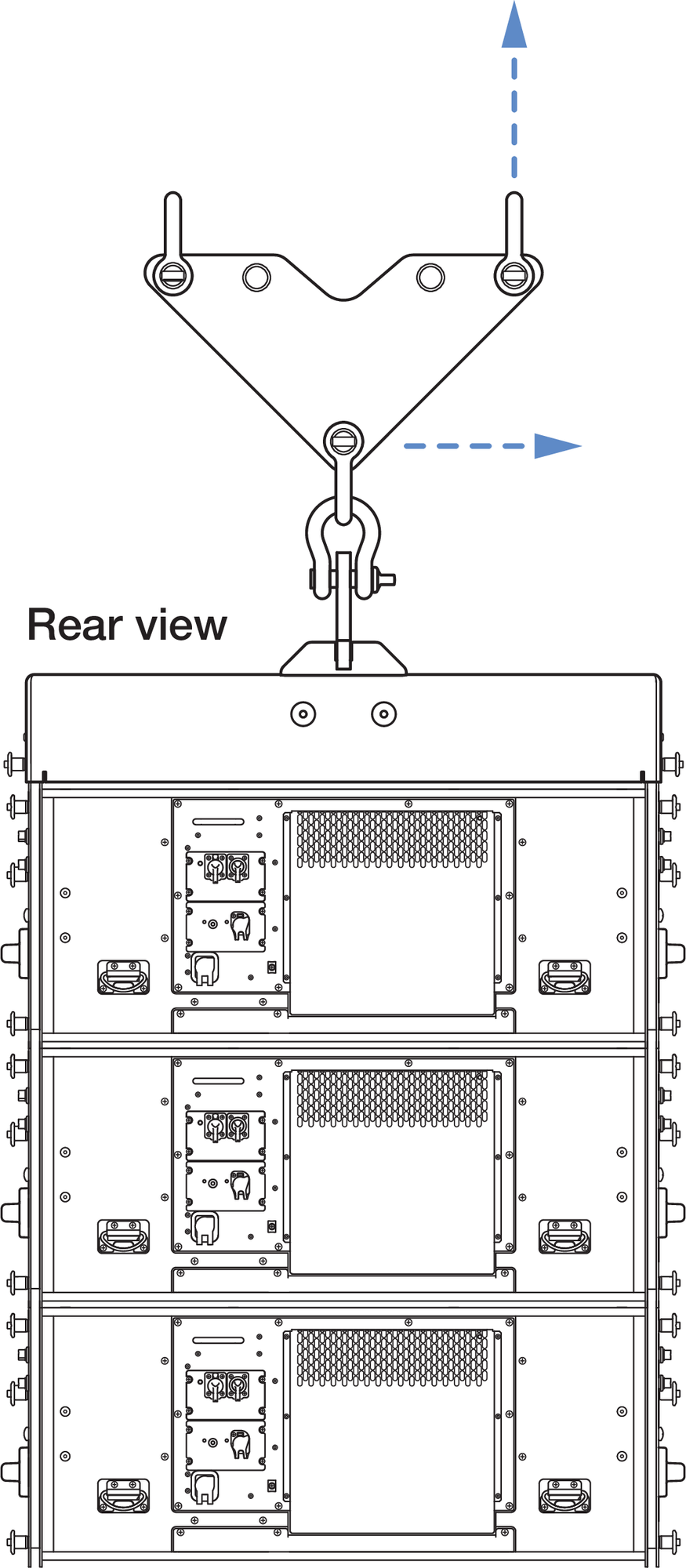
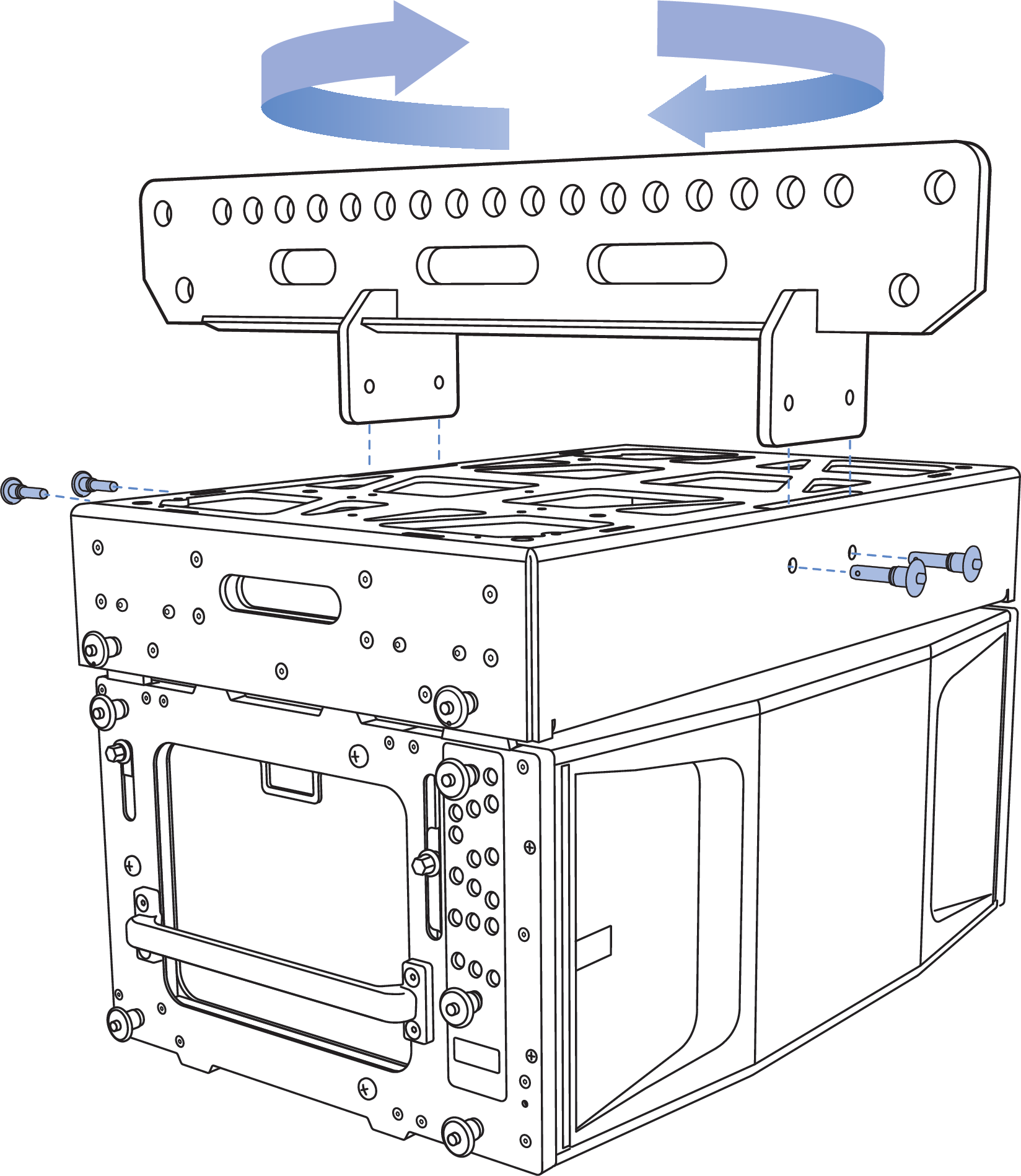
MG-PANTHER Grid Box
The MG-PANTHER Grid Box is symmetrical and can be connected to the top PANTHER cabinet in either orientation.
MG-PANTHER Grid Kit and PANTHER Cabinet, MG-PANTHER Grid Box is Symmetrical, Attached to the PANTHER in Either Orientation
The MG-PANTHER Grid Box is connected to the top PANTHER of an array with four 7/16 x 1.50-inch QRP (red button, PN 134.051) pins that are secured to the MG-PANTHER Grid Box with lanyards. These quick-release pins are not interchangeable with any other pins used with a PANTHER array.
MG-PANTHER Grid Box Connection to Top PANTHER Cabinet
Several attachment points for third-party accessories or equipment racks are available on the top of the MG-PANTHER Grid Box, see the figure below. For accessories weighing more than 50 lb (23 kg), please contact Technical Support before designing or mounting the accessory.
The locations labeled “B” can be used to stow the quick-release pins used to secure the MG-PANTHER Shackle Bar when not in use. The locations labeled “C” align with the mounting holes of third-party brackets used to secure laser/ inclinometers, e.g., ProSight and ProSight2 mounts. Holes labeled “A” and “D” can accommodate the mounting of custom accessories.
For dimensional information, please refer to the CAD (.dwg) drawings available at meyersound.com.
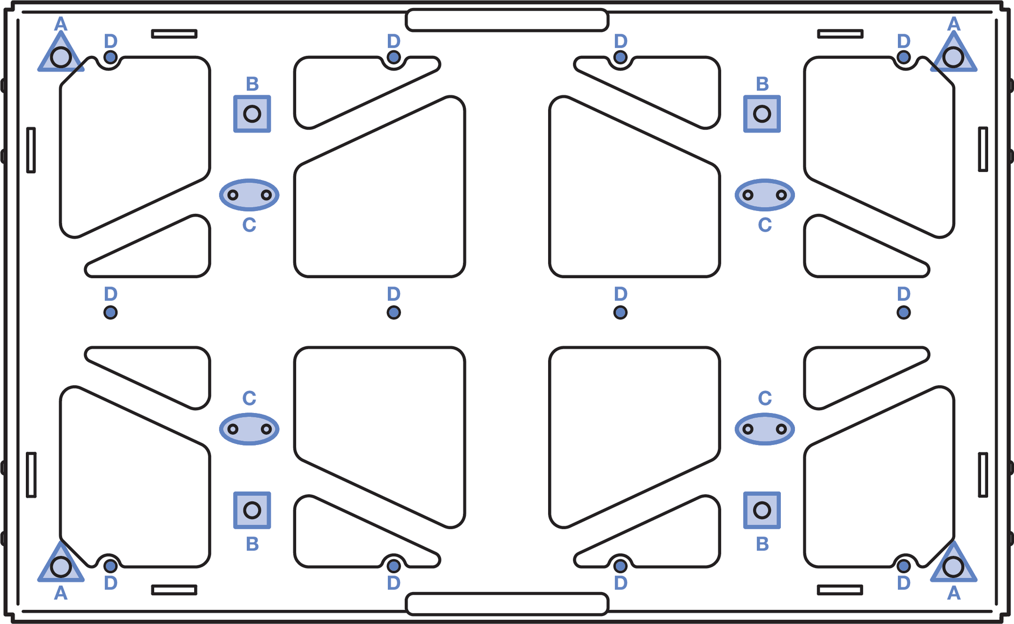
MG-PANTHER Grid Box, Top View
Single-Point Rigging
When suspending an array from a single point of the
MG-PANTHER Shackle Bar, connect the hoist to any hole, 1 through 19. The tilt of the MG-PANTHER Grid Kit is
determined by which hole of the MG-PANTHER Shackle Bar the hoist is connected to.
MG-PANTHER Grid Kit and PANTHER Array, Single-Point Suspension Array
To determine which of the MG-PANTHER Shackle Bar holes to connect the hoist to, model the array in MAPP. Enable the Center of Gravity function and observe where it intersects the MG-PANTHER Shackle Bar. Only when the center of gravity marker intersects the top of one of the holes is the tilt angle achievable. Note the hole number the center of gravity marker intersects. If the desired angle is not achieved, select the opposite grid orientation, forward/ rearward, or consider consulting a qualified rigger to design a bridle with an adjustable leg.
PANTHER Array in MAPP, Center of Gravity Marker Intersecting Hole 18 of the MG-PANTHER Shackle Bar
Dual-Point Rigging
When suspending an array from two points on the MG-PANTHER Shackle Bar, the uptilt or downtilt of the MG-PANTHER Grid Kit is adjusted by changing the height of the front or rear hoists.
MG-PANTHER Grid Kit and PANTHER Array, Dual-Point Suspension
The orientation of the MG-PANTHER Shackle Bar changes where the center of gravity of the array intersects the MG-PANTHER Shackle Bar. To determine which orientation to use, model the array in MAPP and choose the orientation that most evenly distributes the load between the front and rear rigging points.
Rotate the Shackle Bar to Change Shackle Bar Orientation Relative to the PANTHER Cabinets
The MG-PANTHER Shackle Bar orientation relative to the PANTHER cabinets is referred to as “rearward” when maximum uptilt is desired, and “forward” when maximum downtilt is desired.
MG-PANTHER Shackle Bar in Rearward (Maximum Uptilt) and Forward (Maximum Downtilt) Orientations
See Assembling Arrays and Disassembling Arrays for instructions.
PANTHER GuideALinks
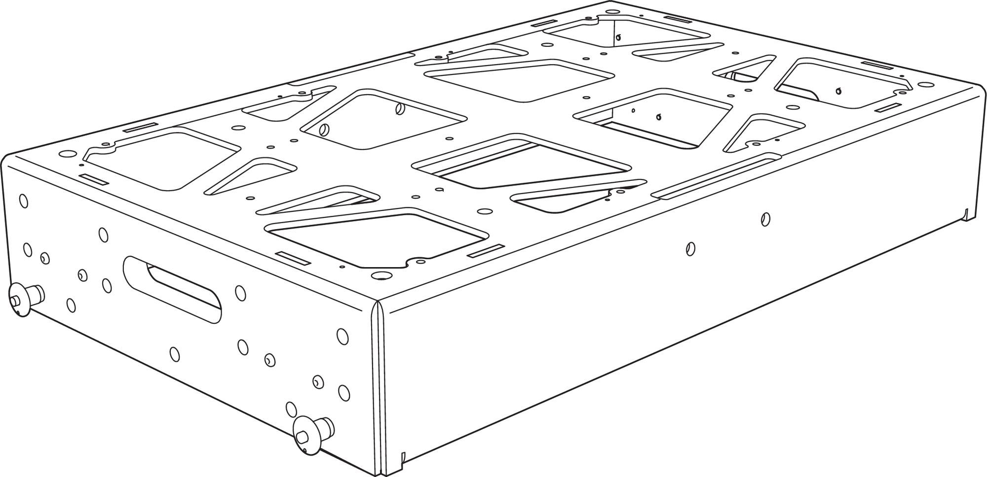
PANTHER loudspeakers are equipped with four captive GuideALinks providing connection to the cabinet above or to the MG-PANTHER Grid Kit. Located at the top corners of the cabinet, the GuideALinks extend into the GuideALink sockets of the cabinet above it or into the GuideALink sockets of the MG-PANTHER Grid Kit. Grasp the hexagonal-shaped knob to raise and lower GuideALinks. The GuideALink position is secured by inserting supplied quick-release pins.
Caution
Never grasp the GuideALink itself to move it. Always use the hex-shaped knob to raise and lower GuideALinks to avoid hand injury.
PANTHER GuideALinks Extended
Caution
Ensure the quick-release pins are fully inserted and locked during array assembly.
The pins are secured to the PANTHER loudspeakers with lanyards. For all pin locations, only use pins whose lanyards are attached to the same cabinet when securing GuideALinks. If a pin with a lanyard attached to one cabinet is used in an adjacent cabinet, the lanyard attachment may be damaged as the array is lifted and the splay angles open.
PANTHER GuideALinks must be secured with the included quick-release pins. At no time should the weight of the loudspeaker rest on the GuideALink knobs when the links are fully extended (without the pins inserted). GuideALink knobs are only used to extend and retract the links.
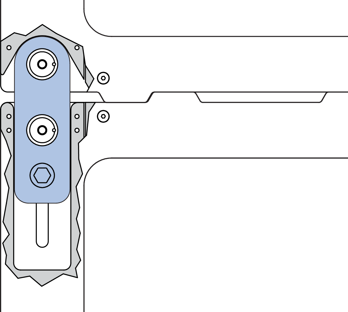
Rear GuideALinks
The rear GuideALinks are the rotation point between linked PANTHER loudspeakers when splayed. The splay angle between cabinets is determined by the front GuideALinks.
PANTHER Rear GuideALink Extended and Pinned.
Front GuideALinks
The front GuideALinks determine the splay angle of the cabinet relative to the cabinet above it. The splay angle is set by inserting one of the included quick-release pins on each side of the cabinet in one of the gray-on-black ANGLE holes. For example, when the front GuideALinks are pinned in place at 5 degrees, the downtilt of the cabinet is 5 degrees more than the downtilt of the cabinet above it.
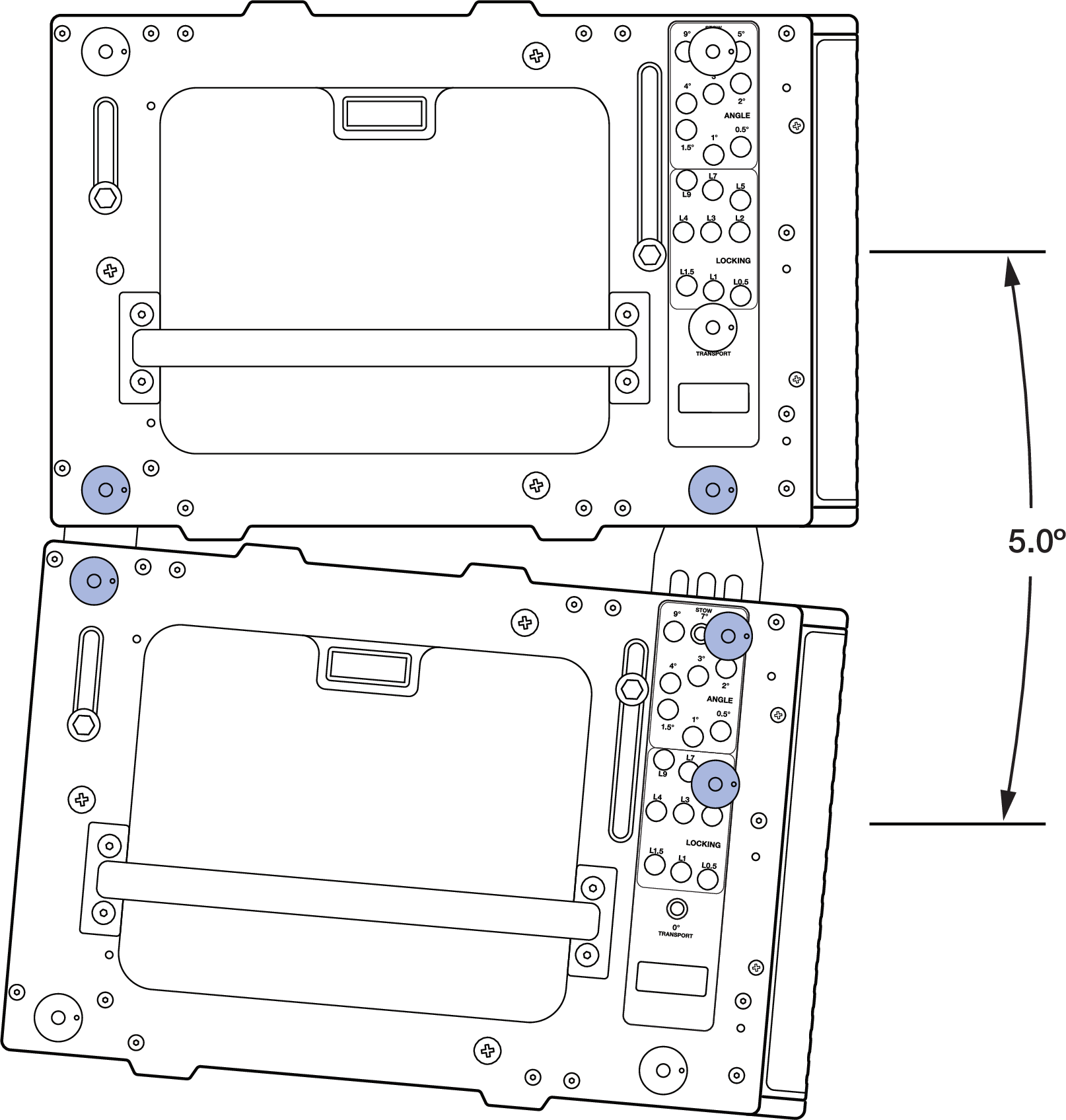
PANTHER GuideALinks Connected at 5 Degrees
The front GuideALinks of the cabinets include 9 ANGLE and 9 LOCK holes. These holes allow quick-release pins to be inserted in one of the ANGLE holes while the cabinets are stacked on caster frames. When the cabinets are lifted, the GuideALinks extend to the desired splay angle and are locked in place by inserting a quick-release pin in the corresponding LOCK hole.
A separate hole labeled 0° GRID / TRANSPORT is used when connecting the top PANTHER of an array to the MG-PANTHER Grid Kit or when transporting PANTHER cabinets.
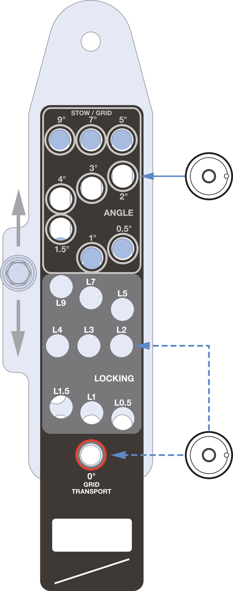
PANTHER Front GuideALink, Hex-Knob
Note
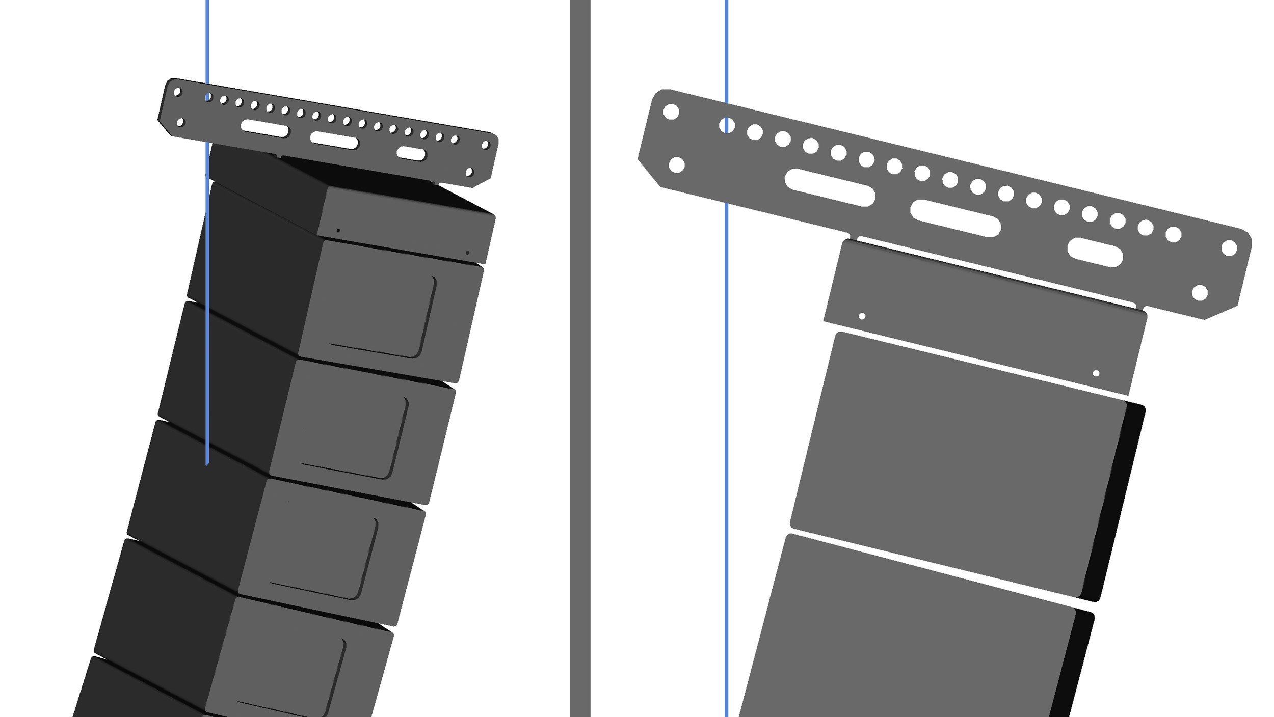
The holes in the GuideALinks are slightly larger than the quick-release pins, which is necessary for array assembly. Due to this small dimensional difference, if multiple cabinets are set to 0° (zero degrees) and the array is tipped down when suspended, the resulting splay angles may be slightly negative rather than positive. The accumulation of the small diameter differences between the GuideALink holes and the quick-release pins can cause the shape of the front of the array to be concave instead of the desired convex shape. When an array is concave in the front, the acoustic output of the array is negatively impacted and should always be avoided. Do not set splay angles to zero degrees except when transporting cabinets.
To optimize the acoustical performance of a PANTHER array, use the appropriate number of loudspeakers with the appropriate splay angles to meet the coverage requirements. Meyer Sound’s MAPP System Design and Prediction software provides the capabilities to determine the optimal array configuration.
See the Assembly and Disassembly Steps for instructions.
PBF-LYON
The optional PBF-LYON pull-back frame attaches to the bottom cabinet of PANTHER arrays. This accessory allows for both pull-up and pull-back configurations. The PBF-LYON Pull-Back Frame is secured to a PANTHER cabinet with two quick-release pins included with PANTHER, 7/16 x 0.90-inch QRP (black button, PN 134.065).
PBF-LYON Pull-Back Frame and Bottom of PANTHER Array
PBF-LYON Pull-Back Frame Kit Contents
Table 6. PBF-LYON Pull-Back Frame Kit, PN 40.232.125.01
Quantity | Part Number | Item |
|---|---|---|
1 | 45.232.125.01 | PBF-LYON Pull-Back Frame |
PBF-LYON Pull-Back Frame Dimensions
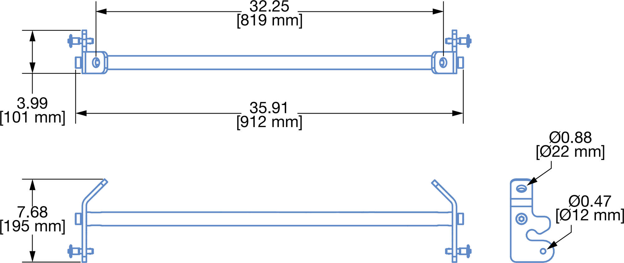
PBF-LYON Pull-Back Frame Dimensions
PBF-LYON Pull-Back Frame Load Rating
The PBF-LYON pull-back frame has the following load rating: 5:1 safety factor, 3400 lbs (1542 kg)
Caution
The rigging hardware connected to a PBF-LYON Pull-Back Frame must be sufficiently rated for the load, e.g., hoists, wire rope, shackles.
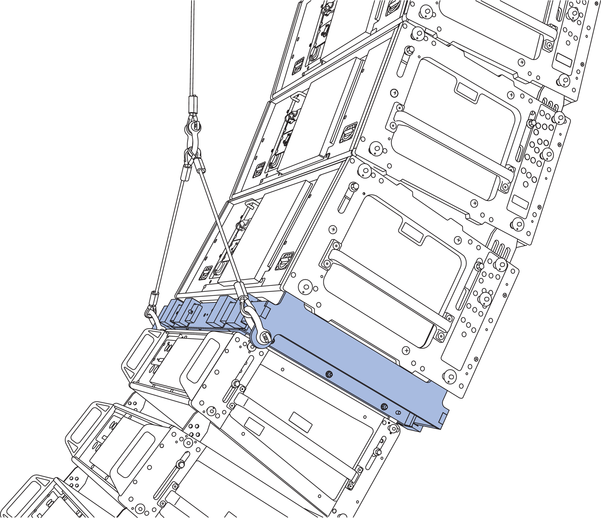
PBF-LYON Pull-Back Frame Rigging
Use rated 5/8-inch shackles to connect rated bridle hardware to the connection points at the ends of the PBF-LYON Pull-Back Frame. Use another rated 5/8-inch shackle to connect the two ends of the bridle.
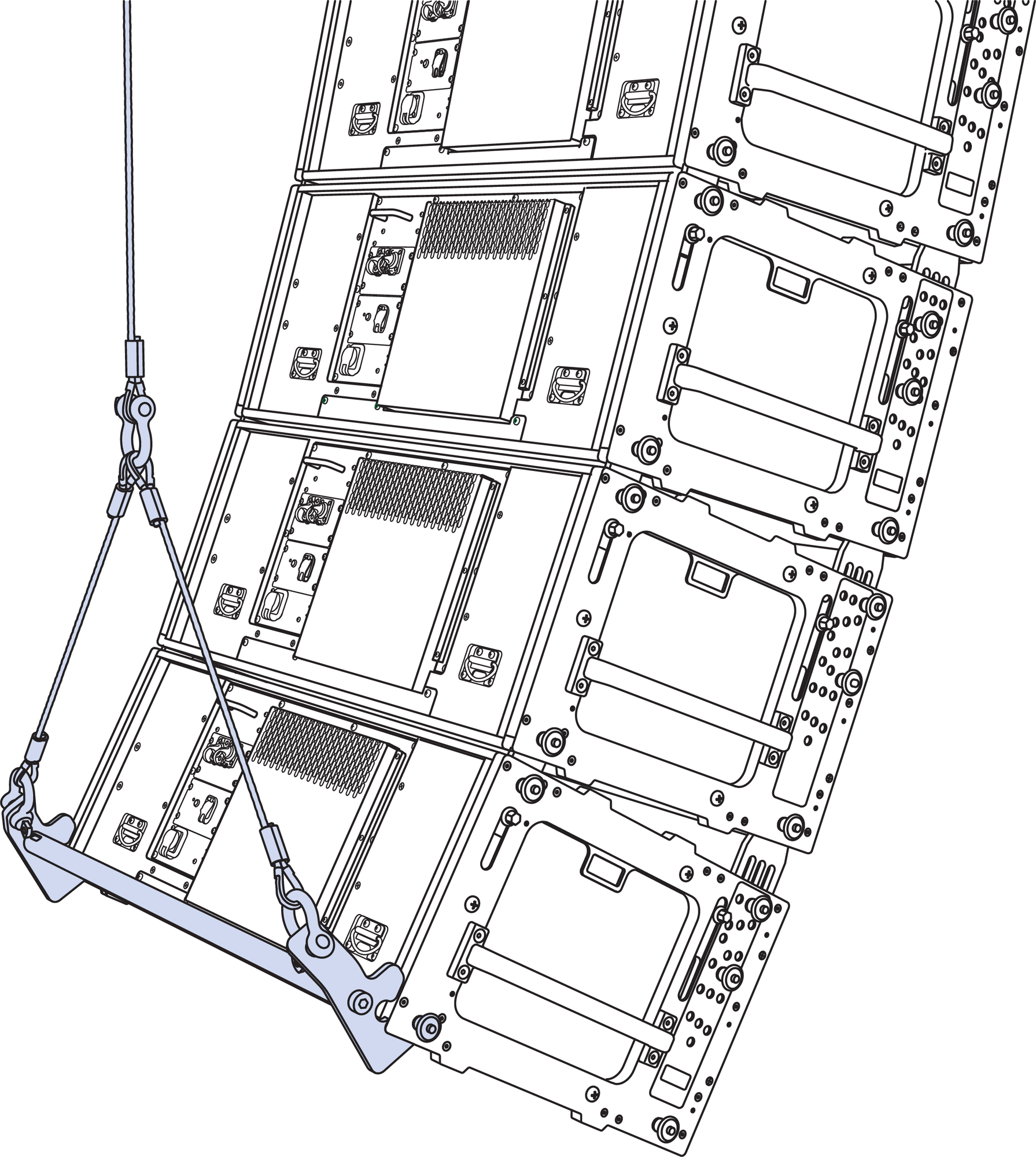
PBF-LYON Pull-Back Frame Connected to Bottom of PANTHER Array
Caution
The minimum length of the bridle legs connected to the PBF-LYON Pull-Back Frame image94.pngis 23 inches (584 mm) based on the bridle apex angle being less than 90 degrees.
Pull-Back Configuration Overview
In the pull-back configuration, the PBF-LYON Pull-Back Frame provides additional downtilt beyond what is possible with the MG-PANTHER Grid Kit alone.
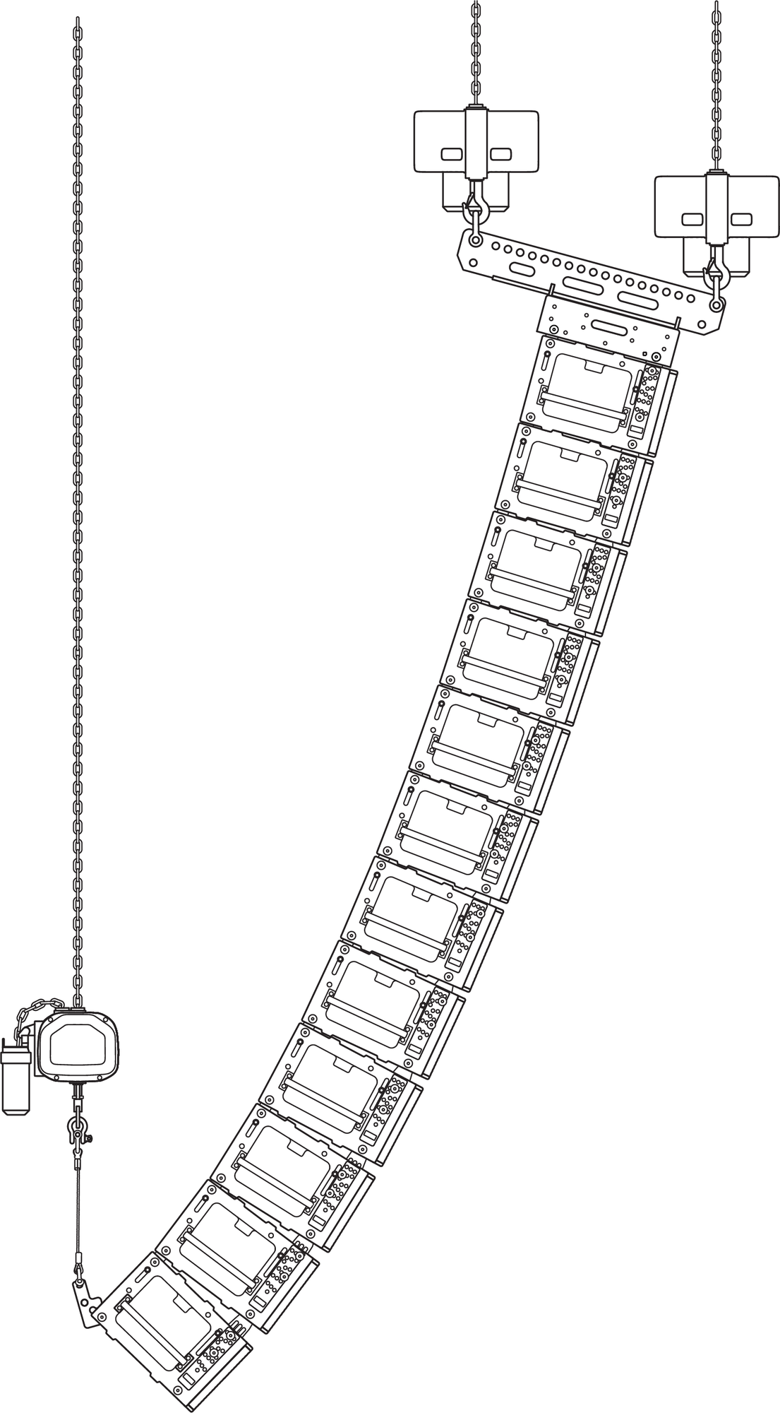
PBF-LYON, Pull-Back Configuration, Three Hoists
While designing an array in MAPP, if the desired array downtilt is not achievable, MAPP indicates this in several ways:
The Center of Gravity marker is behind the rear-most hole of the MG-PANTHER Shackle Bar
The Front Rigging Load value is negative
The Safety Limits Analysis displays, “Configuration COG is outside of Grid Pickup Points”
If the array design would benefit from additional downtilt, use the PBF-LYON in the pull-back configuration.
Caution
The pull-back configuration requires three hoists, two mounted to the MG-PANTHER Shackle Bar (holes 1 and 19), and one hoist connected to the PBF-LYON Pull-Back Frame.
When configuring arrays for pullback, the angle of the rigging hardware between the PBF-LYON Pull-Back Frame and the structural attachment point should not be more than ±10 degrees from vertical when the array is in its final position. This requires the structural attachment point of the hoist be properly located.
: When an array is suspended in the pull-back configuration, the load of the array must be shared between the pull-back hoist and the rear MG-PANTHER Shackle Bar hoist, with just enough load carried by the front MG-PANTHER Shackle Bar hoist to tension the rigging hardware. If the front hoist carries more load than the rear hoist, the array may be unstable and unintended rotation of the array could occur.
Use MAPP to determine rigging limits when an array is deployed in the pull-back configuration. The quantity of cabinets, amount of array downtilt, and rigging loads are used to calculate the safety limits
Note
The MVP Motor V Plate is not intended for use when the array is in the pull-back configuration as it provides insignificant horizontal rotation of an array in the pull-back configuration.
Pull-Up Configuration Overview
The pull-up configuration requires a manual hoist be connected between the PBF-LYON Pull-Back Frame and the lower utility point of the MG-PANTHER Shackle Bar. In this configuration, one or two hoists can be connected to the MG-PANTHER Shackle Bar. If desired, the MVP Motor V Plate can be connected to an array deployed in the pull-up configuration.
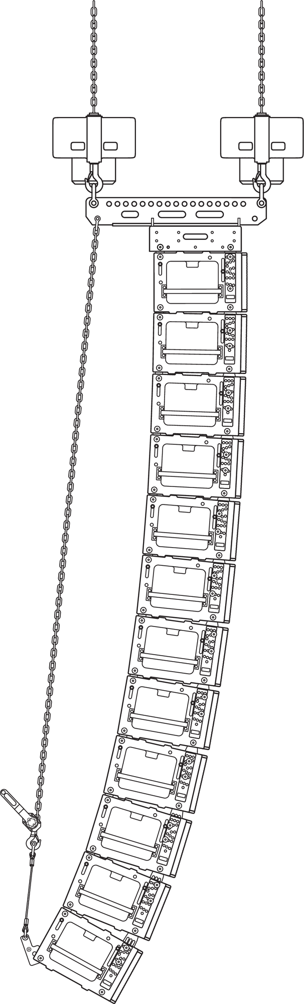
PBF-LYON, Pull-Up Configuration
When 12 or more PANTHER are used in an array, there are three scenarios in which the pull-up configuration is recommended:
During array assembly, if the GuideALinks do not fully extend when the array is lifted and the MG-PANTHER Grid Kit is tipped up as much as possible (upstage hoist slacked), the holes in the end frame and the GuideALink will not align, not allowing the LOCK pins to be inserted. Attempt to fully extend the front GuideALinks by pushing down on the handles on the sides of the cabinet. If this does not fully extend the front GuideALinks, configure the array for pull- up. When the manual hoist is tensioned, the front GuideALinks will fully extend allowing the LOCK pins to be easily inserted.
During array assembly, if the flown cabinets are tilted up as much as possible (upstage hoist slacked) and the rear GuideALinks of the stacked cabinets cannot be seated in the GuideALink sockets of the flown cabinet, configure the array for pull-up.
When trimmed, if the majority of the front GuideALinks of an array are in compression, the tight tolerance between the GuideALink holes and the quick-release pin diameters can accumulate, resulting in the lower cabinets of an array not achieving their desired downtilt. The pull-up configuration relieves the compression on the front GuideALinks, resulting in all the cabinets being aimed as intended.
Additional Equipment
The pull-up configuration requires a user-provided manual hoist. This hoist is connected between the bridle of the PBF-LYON and the lower utility point on the MG-PANTHER Shackle Bar. The lifting capacity of the hoist should be
less than 3400 lbs (1542 kg) to prevent overloading the PBF-LYON Pull-Back Frame. For use with all possible arrays, the minimum lifting capacity of the hoist should be at least 1500 lb (680 kg).
Manual Hoist Example
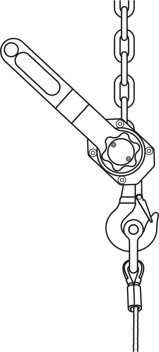
The Columbus McKinnon (CM) Tornado 360 Ratchet Lever Hoist is one such device. For this hoist, two accessory items available from CM are needed:
chain, length determined by the distance between the PBF-LYON and MG-PANTHER Shackle Bar utility point
chain shortening mechanism to reduce the “working” length, reduces the amount of chain taken up before load is carried
See Assembling Arrays and Disassembling Arrays, for instructions.
MTF-LYON/LEOPARD Transition Frame
With some restrictions, the optional MTF-LYON/LEOPARD transition frame suspends up to 10 LEOPARD cabinets
at a 5:1 safety factor below PANTHER arrays for downfill. The transition frame attaches to the bottom cabinet in the PANTHER array at an angle of 0 degrees and is secured with the quick-release pins included with PANTHER.
The top LEOPARD cabinet attaches to the transition frame’s inner link slots and is secured with four 5/16 x 0.875-inch quick-release pins (red button) included with the transition frame. The configuration of GuideALinks of the top LEOPARD cabinet determines the angle of its attachment, from –4.5 to +10 degrees.
The MTF-LYON/LEOPARD transition frame is collapsible for easy transport (see Collapsing the MTF-LYON/LEOPARD Transition Frame). This transition frame also includes rear pickup points for pull-back and pull-up (see Using the MTF-LYON/ LEOPARD Transition Frame for Pull-Back and Pull-Up.
PANTHER Array, MTF-LYON/LEOPARD Transition Frame, LEOPARD Array
Caution
When flying combined arrays, the total weight of the array, including any transition and pull-back hardware, should be calculated before the array is flown to verify that the weight does not exceed the load ratings.
Always use the 5/16 x 0.875-inch quick-release pins (red button) included with the MTF-LYON/LEOPARD transition frame to secure the attached LEOPARD. Do not use the 5/16 x 0.63-inch quick-release pins (black button) included with LEOPARD in the transition frame as they are shorter and will not lock in place.
Always use properly rated rigging hardware. The MTF-LYON/LEOPARD transition frame requires 1/2-inch or 5/8-inch shackles for its pickup points.
MTF-LYON/LEOPARD Transition Frame Kit Contents
Qty | Part Number | Item | |
|---|---|---|---|
 | 1 | 45.232.140.01 | MTF-LYON/LEOPARD transition frame |
 | 8 | 134.025 | 5/16 x 0.875-inch quick-release pins (red button) |
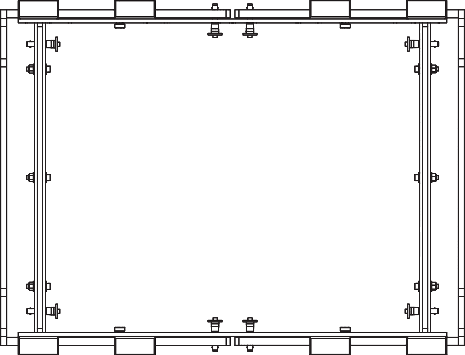
MTF-LYON/LEOPARD Transition Frame Dimensions
The MTF-LYON/LEOPARD transition frame collapses horizontally so it can travel installed on top of LEOPARD stacks on the MCF-LEOPARD caster frame. When the transition frame is collapsed, it occupies a smaller footprint than the MCF-LEOPARD caster frame.
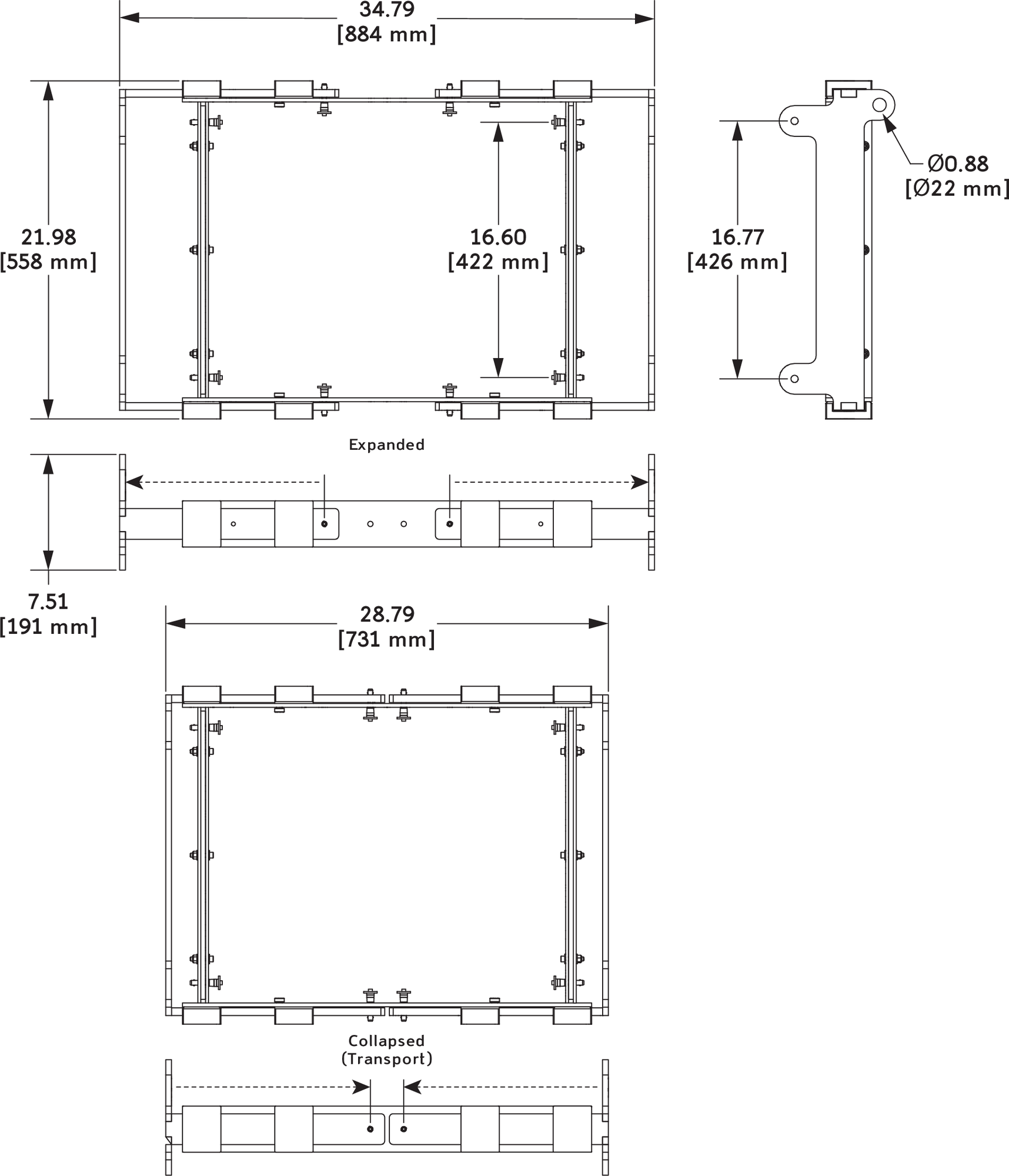
MTF-LYON/LEOPARD Transition Frame Dimensions
Collapsing the MTF-LYON/LEOPARD Transition Frame
The MTF-LYON/LEOPARD transition frame collapses horizontally so it can travel installed on top of LEOPARD stacks on the MCF-LEOPARD caster frame. When the transition frame is collapsed, it occupies a smaller footprint than the MCF-LEOPARD caster frame.
MTF-LYON/LEOPARD Transition Frame Collapsed
Before attaching the MTF-LYON/LEOPARD transition frame to a PANTHER array, expand the frame and lock it with the included 5/16 x 0.875-inch quick-release pins (red button).
MTF-LYON/LEOPARD Transition Frame, Expanded
MTF-LYON/LEOPARD Transition Frame Load Ratings (Loudspeaker)
The table below lists the maximum number of LEOPARD cabinets that can be suspended below PANTHER arrays with the MTF-LYON/LEOPARD transition frame. The configuration of the PANTHER array greatly affects the load ratings for the attached MTF-LYON/LEOPARD transition frame. In addition, the number of LEOPARD cabinets suspended below the PANTHER array greatly affects the load rating of the MTG-PANTHER Grid Kit.
Number of Flown PANTHERs | Maximum Flown LEOPARD cabinets (No Restrictions) | Maximum Flown LEOPARD cabinets (with Restrictions) |
All Splay Angles Allowed | PANTHERs in Top Half of Array with Splay Angles of 2° or Less, PANTHERs in Bottom Half of Array with Splay Angles of 5° or Less, LEOPARD cabinets with Any Splay Angle | |
5:1 Safety Factor | 5:1 Safety Factor | |
6 | 10 | 10 |
7 | 9 | 10 |
8 | 9 | 10 |
9 | 9 | 10 |
10 | 9 | 10 |
11 | 9 | 9 |
12 | 7 | 9 |
13 | 4 | 9 |
14 | 2 | 9 |
15 | 8 | |
16 | 6 | |
17 | 4 | |
18 | 2 |
Caution
Do not exceed the load ratings to avoid potential risk of personal injury and/or equipment damage. To verify pull-back load ratings, model the array in MAPP prediction software.
When flying combined arrays, the total weight of the array, including any transition and pull-back hardware, should be calculated before the array is flown to verify the weight does not exceed the load ratings.
Note
Additional array configurations for the MTF-LYON/LEOPARD transition frame are possible. Model the array in MAPP prediction software to determine whether a configuration exceeds the load ratings or not.
Using the MTF-LYON/LEOPARD Transition Frame for Pull-Back and Pull-Up
The MTF-LYON/LEOPARD transition frame includes two rear pickup points that provide pull-back for extreme array downtilts. The pickup points can also be used for pull-up to expand the PANTHER array’s splay angles during installation so the LOCK pins can be more easily inserted. The MTF-LYON/LEOPARD transition frame requires 1/2- inch or 5/8-inch shackles for its pickup points.
When the MTF-LYON/LEOPARD transition frame is used for pull-back, to tilt the array, the transition frame must be hoisted by a motor separate from and behind the MG-PANTHER Grid Kit. The pull-back motor must not be attached to the grid.
MTF-LYON/LEOPARD Transition Frame with Pull-Back
Caution
When configuring arrays with pull- back, when in final position, the pull-back chain should not be greater than ±10 degrees from vertical.
When the MTF-LYON/LEOPARD transition frame is used for pull-up, to expand the PANTHER array’s splay angles during installation so the LOCK pins can be more easily inserted, the transition frame is hoisted by a manual hoist located between the transition frame and the utility hole of the MG- PANTHER Shackle Bar.
Caution
When flying combined arrays, the total weight of the array, including any transition and pull-back hardware, should be calculated before the array is flown to verify that the weight does not exceed the load ratings.
Always use properly rated rigging hardware. The MTF-LYON/LEOPARD transition frame requires 1/2-inch or 5/8-inch shackles for its pickup points.
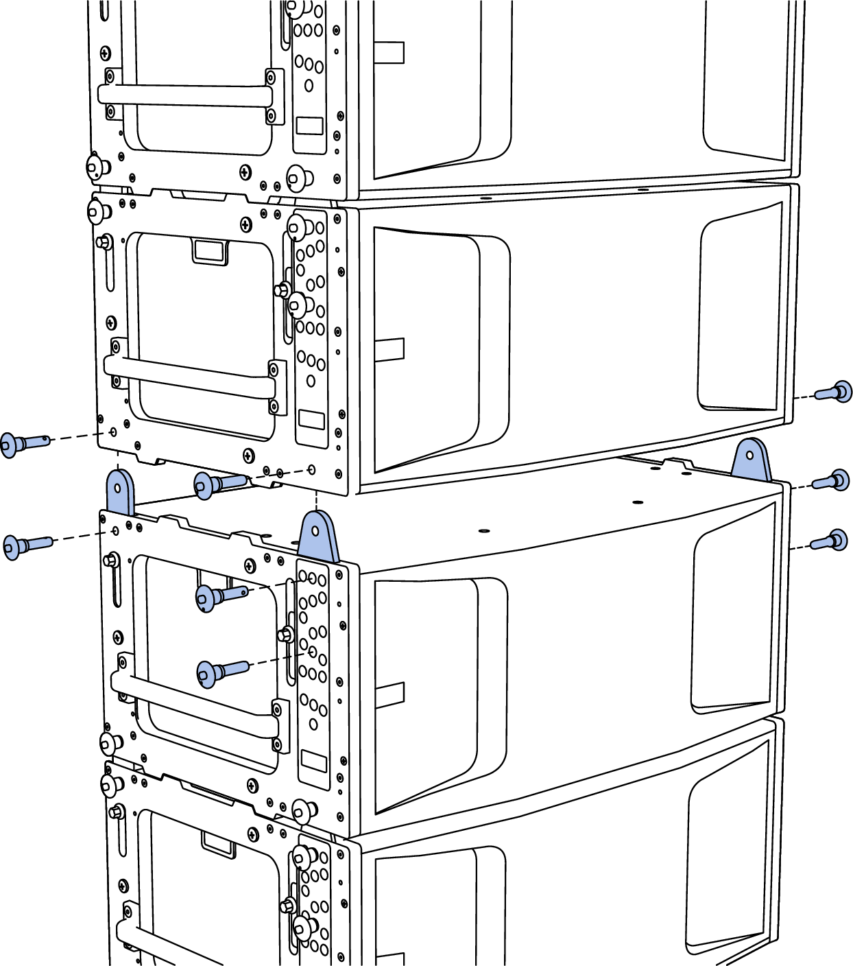
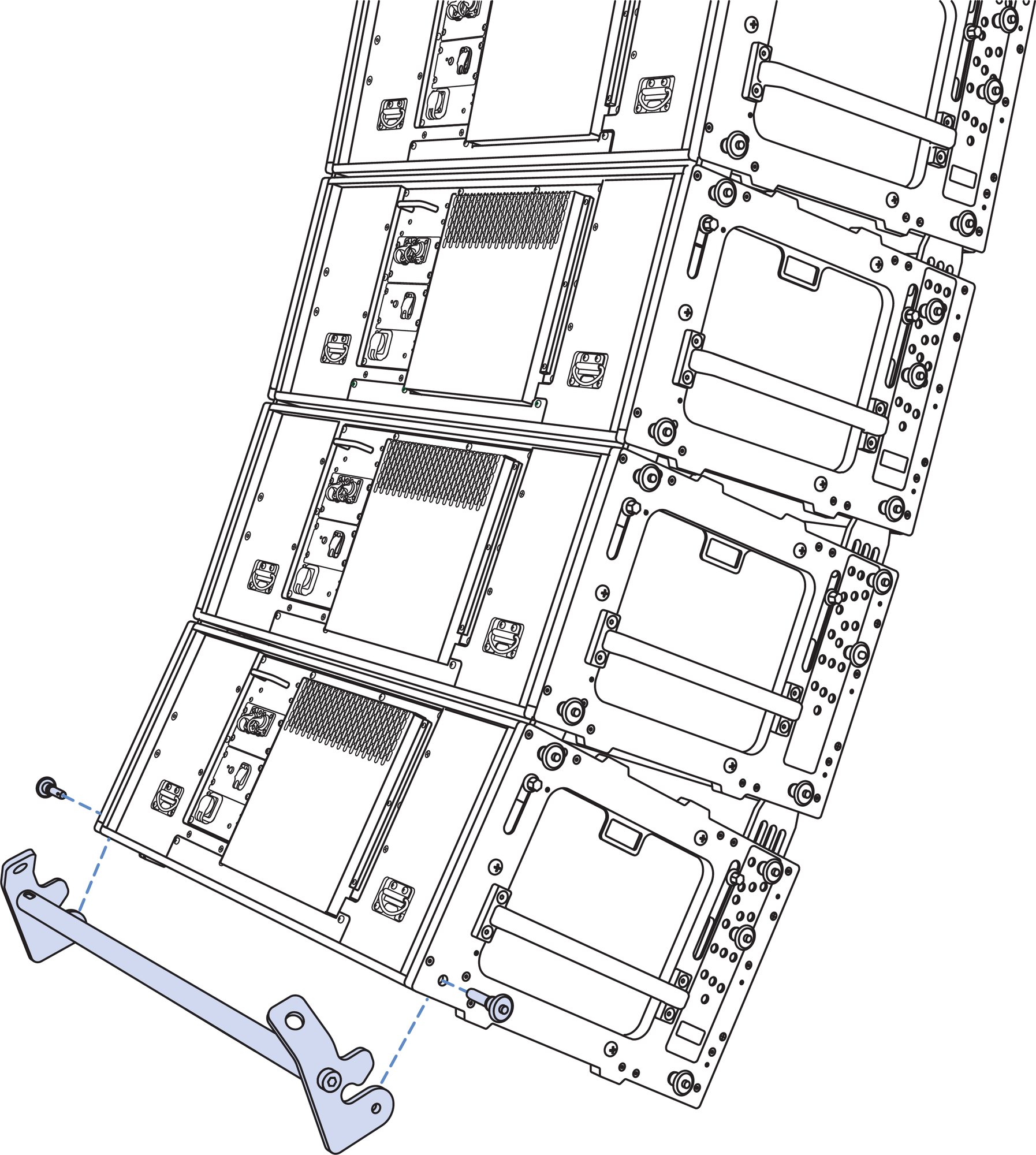
MCF-PANTHER Caster Frame
The MCF-PANTHER Caster Frame safely transports up to four PANTHER loudspeakers and an MG-PANTHER Grid Box making it easy to assemble and disassemble arrays in groups of four cabinets.
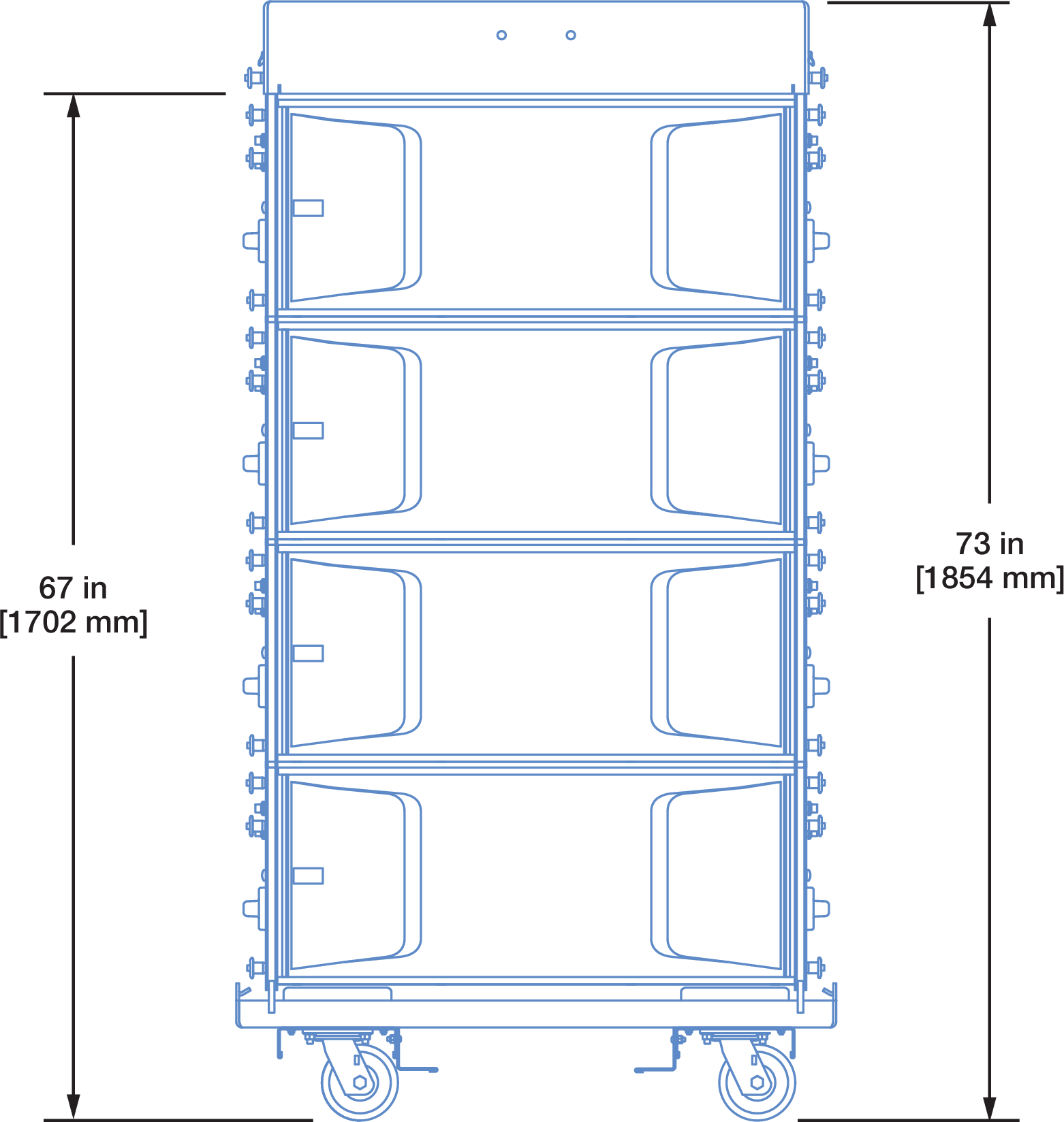
Dimensions of MG-PANTHER Grid Box, Four PANTHER Cabinets, MCF-PANTHER Caster Frame
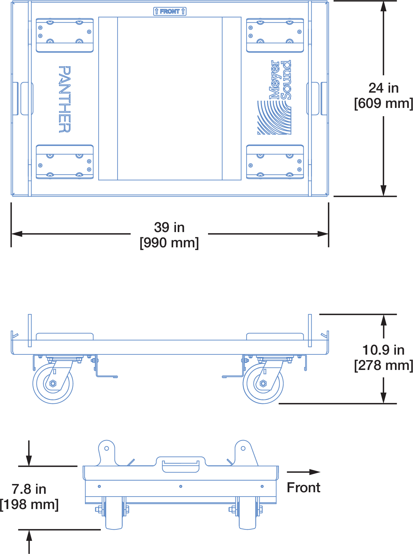
MCF-PANTHER Caster Frame Dimensions
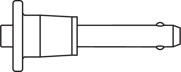
The caster frame includes four fixed attachment points that align with the GuideALink sockets of the bottom PANTHER of an array. The caster frame is secured with the quick-release pins included with PANTHER, 7/16 x 0.90-inch QRP (black button, PN 134.065).
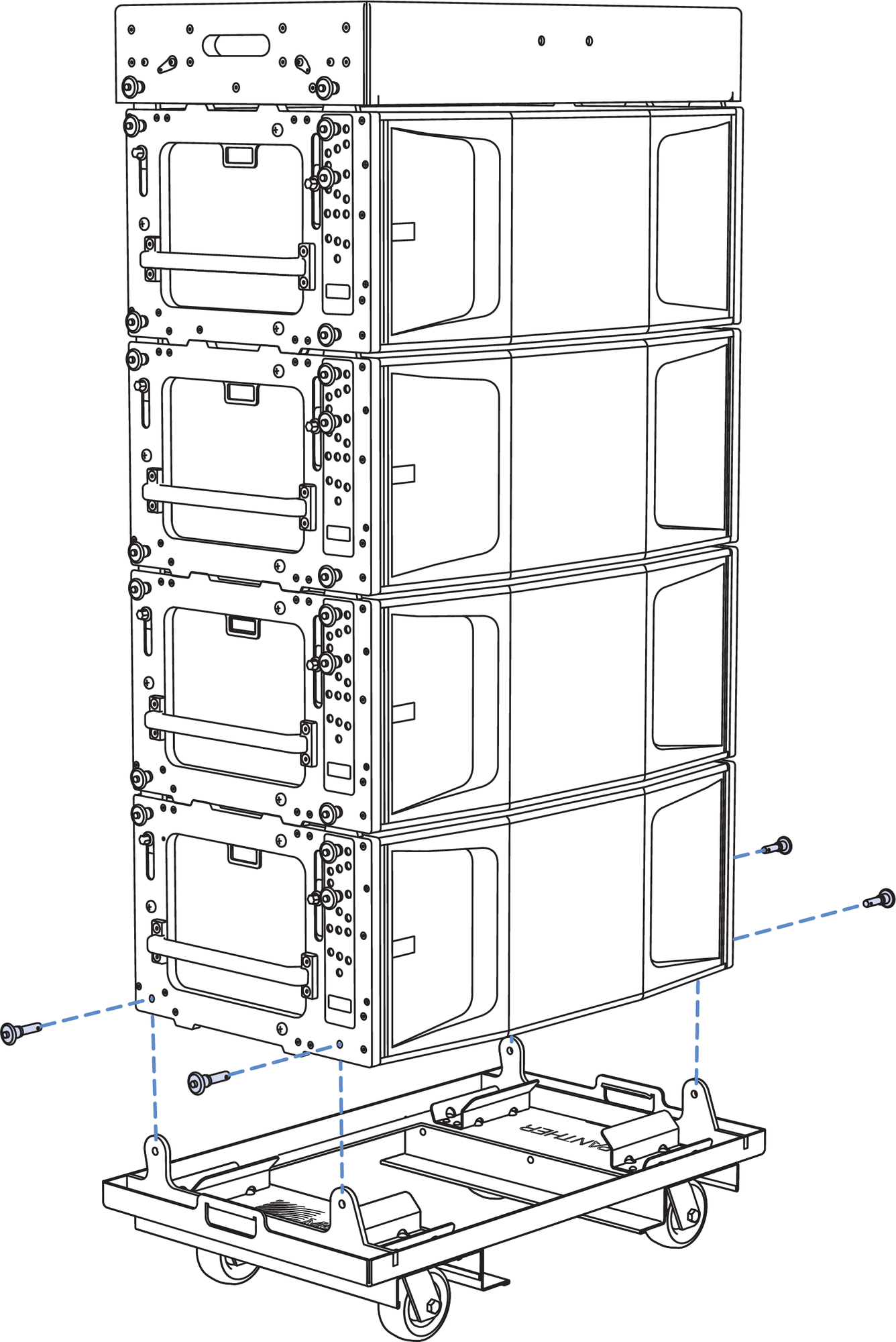
MCF-PANTHER Caster Frame with PANTHER Stack
Caution
Do not transport 4-high stacks of PANTHER with the MG-PANTHER Shackle Bar attached to the Grid Box. This exceeds the safety limits for tip-over, which may cause injury.
Tip
Durable, 4-high nylon covers are available to ensure the PANTHER cabinets are protected during transport.
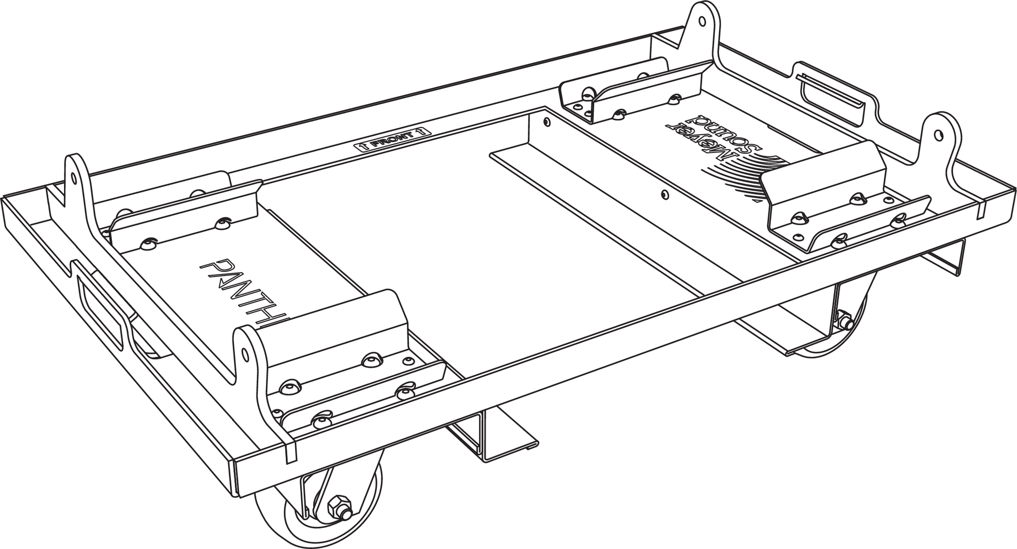
The caster frame includes forklift guides between the wheels to prevent damage to them.
MCF-PANTHER Caster Frame with PANTHER Stack
If desired, the forklift guides can be removed without affecting the structural integrity. Remove the three bolts securing each of the guides.
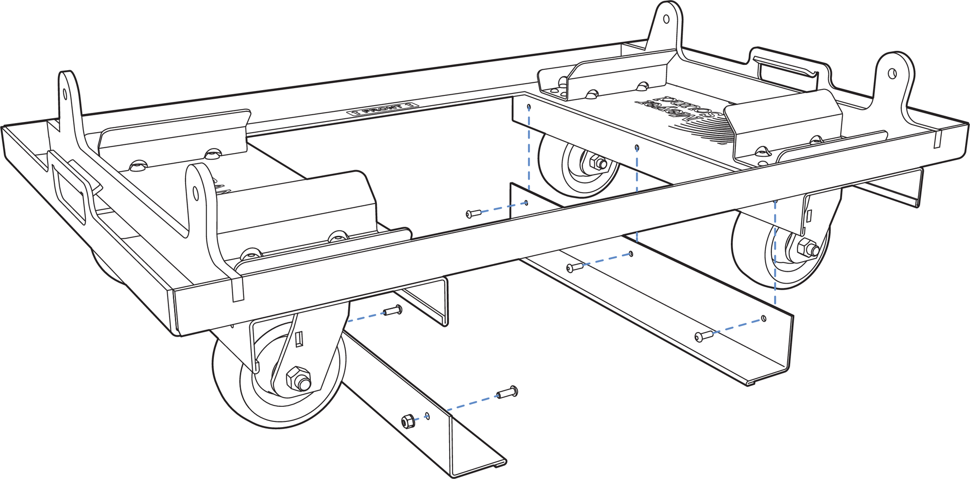
MCF-PANTHER Caster Frame, Forklift Guides Removed
Safety Guidelines for the MCF-PANTHER Caster Frame
While the MCF-PANTHER Caster Frame supports up to four cabinets plus the MG-PANTHER Grid Box, use extreme caution when moving the caster frame and cabinets to avoid tipping.
When rolling a caster frame and cabinets, slow down when the surface is uneven, e. g., cracks in concrete floors, cable ramps, transitions in floor coverings, etc.
Do not move stacks in the front-to-rear direction of the PANTHER cabinets (the long side) as the risk of injury increases. Always move stacks sideways to avoid tipping.
When moving the caster frame with PANTHER cabinets, always use the handles of the cabinets and push or pull from one of the ends.
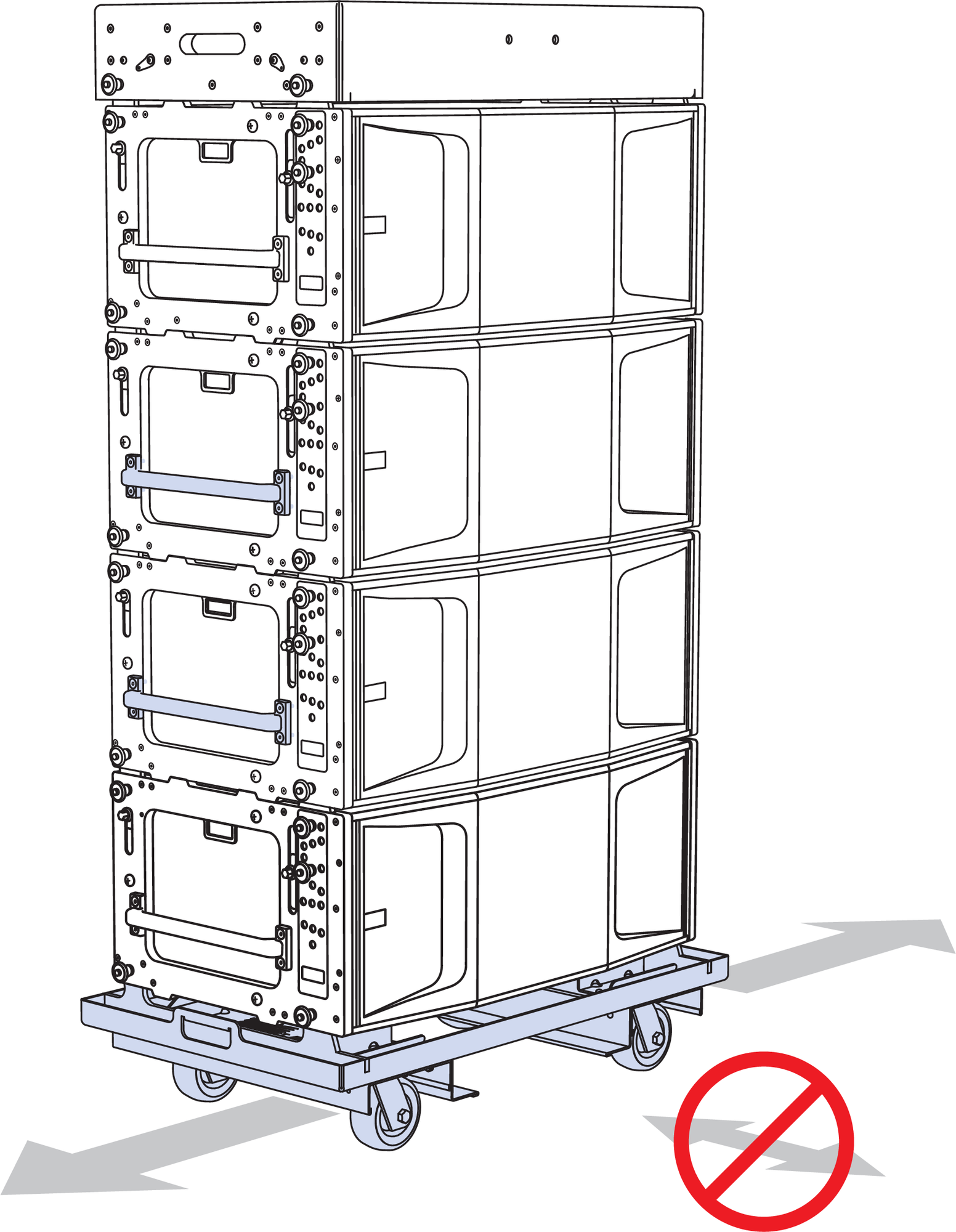
MCF-PANTHER Caster Frame with PANTHER Stack
To avoid tipping, transport stacks with all the GuideALinks connected to adjacent cabinets. The front links should be secured with pins inserted in the 0° GRID / TRANSPORT hole, below the white- on-gray LOCK holes. The pins in the gray-on-black ANGLE holes can be in any position, except when connecting to the MG-PANTHER Grid Box, insert a pin in the gray-on-black STOW / GRID 7° hole.
The caster frames must be removed before the array is flown.