Ashby Power and Input Channel
The Ashby-5C and Ashby-8C loudspeakers require a Meyer Sound MPS IntelligentDC Power Supply to function properly. The MPS-488HP, for example, can power up to 24 Ashby-5C (3 per channel) or 16 Ashby-8C (2 per channel).
Ashby loudspeakers receive DC power (-, +) and balanced audio (+, -, shield) from a Phoenix 5-pin male input connector. The pins are clearly labeled on the Ashby Power and Input panel shown below.
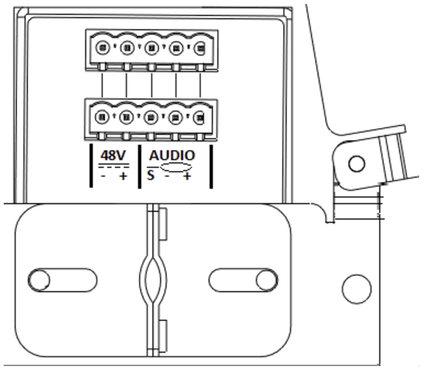
Ashby Power and Input panel
Looping
Ashby loudspeakers can be looped using the connectors on the Ashby Power and Input panel. The table below shows the maximum number of loudspeakers that can be looped from one channel of an MPS Power Supply to function properly and meet compliance requirements.
Model | Maximum Number |
|---|---|
Ashby-5C | 3 (2 looped) |
Ashby-8C | 2 (1 looped) |
Mixed | 1 Ashby 8C 1 Ashby 5C |
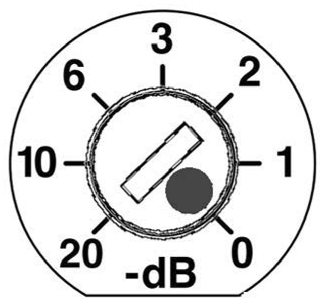
Loudspeaker Attenuator Knob
All Ashby loudspeakers powered by a single channel of an MPS Power Supply receive the same DC voltage and the same audio signal. To set loudspeakers to different levels, use the Loudspeaker Attenuation knob (on Ashby loudspeakers equipped with this feature).
The Loudspeaker Attenuator knob (shown below) is located on the front bezel. Possible values are: 1, 2, 3, 6, 10, and 20 dB.
Ashby Power and Input panel
Cable Specification
Each loudspeaker ships with two Phoenix 5-pin, male cable-mount connectors for loudspeaker cable assembly (see Assembling Phoenix-to-Phoenix Loudspeaker Cables).
A single composite cable (e.g., Belden 1502) can route DC power and balanced audio to the Ashby loudspeakers (see Belden 1502 Cable).
It is extremely important to connect each pin correctly. Maintain proper polarity (- to -, + to +) or system performance will degrade and possibly damage can occur to the loudspeaker (see Assembling Phoenix-to-Phoenix Loudspeaker Cables).
Caution
Connect the 48 VDC directly (and only) from the external power supply to the 48 VDC pins on the loudspeaker connector.
Current Draw
DC current draw for Ashby loudspeakers is dynamic and fluctuates with changing operating levels. As the cable length increases between an Ashby loudspeaker and its external power supply, so does the resistance, which can eventually cause a voltage drop at the loudspeaker. This can compromise amplifier performance, peak SPL, and frequency response. The next section shows how to select the right cable gauge for each loudspeaker.
Cable Length and Gauge
The maximum cable length depends on the type and number of loudspeakers looped and the gauge of the cable. Table 1 shows the maximum cable length for Ashby loudspeakers using 18 AWG cable with only 1 dB of peak SPL loss.
Caution
The minimum cable gauge and type of wire must conform with national and regional electrical and building codes where loudspeakers are installed. The maximum number of loudspeakers, shown in the first table below, results in a maximum 3-second average power within Class 2 wiring limits in most countries.
Using 18 AWG wire, a single Ashby-5C loudspeaker can use up to 450 ft of cable (300 ft for Ashby-8C) from the MPS Power Supply and lose no more than 1 dB of peak SPL. Unlike 70 V line-distributed loudspeakers, Ashby loudspeakers do not suffer gain loss with the long 18 AWG cables.
Model | Number of loudspeakers | Maximum Cable Length (ft) |
|---|---|---|
Ashby-5C | 1 | 450 |
2 | 225 | |
3 | 150 | |
Ashby-8C | 1 | 300 |
2 | 150 |
The table below shows the maximum cable runs for a single channel of an MPS Power Supply powering up to 3 Ashby-5C or two Ashby-8C with different wire gauges. The last table below shows the same information for European cable gauges.
Maximum Cable Length (ft) | |||||
|---|---|---|---|---|---|
Model | Number of Loudspeakers | 12 AWG 0.0016 (Ω/ft) | 14 AWG 0.00253 (Ω/ft) | 16 AWG 0.00402 (Ω/ft) | 18AWG 0.00636 (Ω/ft) |
Ashby-5C | 1 | 1800 | 1125 | 700 | 450 |
2 | 900 | 550 | 350 | 225 | |
3 | 600 | 375 | 237 | 150 | |
Ashby-8C | 1 | 1200 | 750 | 475 | 300 |
2* | 600 | 375 | 237 | 150 | |
*Also applies to one Ashby-8C with one looped Ashby-5C
Note
Some high frequency loss can occur from long analog audio cables. For lengths greater than 500 ft (indicated by the gray background in the maximum cable length tables), Meyer Sound recommends using low capacitance shielded audio cable or AES Digital audio cable. Discuss expected high frequency loss with the cable manufacturer to determine acceptability.
Maximum Cable Length (m) | |||||
|---|---|---|---|---|---|
Model | Number of Loudspeakers | 2.5 mm2 0.0052 (Ω/m) | 1.5 mm2 0.01076 (Ω/m) | 1.0 mm2 0.02087 (Ω/m) | 0.75 mm2 0.03307 (Ω/m) |
Ashby-5C | 1 | 480 | 260 | 135 | 80 |
2 | 240 | 130 | 70 | 40 | |
3 | 160 | 87 | 45 | 27 | |
Ashby-8C | 1 | 320 | 175 | 90 | 55 |
2* | 160 | 87 | 45 | 27 | |
*Also applies to one Ashby-8C with one looped Ashby-5C
Note
Some high frequency loss can occur from long analog audio cables. For lengths greater than 150 m (indicated by the gray background in the maximum cable length tables), Meyer Sound recommends using low capacitance shielded audio cable or AES Digital audio cable. Discuss expected high frequency loss with the cable manufacturer to determine acceptability.
The maximum total cable resistance between one Ashby-5C loudspeaker and its external power supply is 6 Ω, and 4 Ω for one Ashby-8C.
When using the maximum number of loudspeakers per channel (3 Ashby-5C or 2 Ashby-8C), it should not exceed 2 Ω.
Calculating the Maximum Cable Length
The maximum cable length for an Ashby loudspeaker can be calculated using the formulas shown below. The Wire Resistance Per Foot (WRPF) is the resistance (in Ω) for one foot of individual wire of the chosen gauge. Enter the WRPF in the equations below to determine maximum cable length. The equations compensate for round trip length.
For 18 AWG, WRPF = 0.006385 Ω/ft
Ashby-5C: Maximum length (ft) = 3 Ω/ (WRPF x # of Ashby-5C)
Ashby-8C: Maximum length (ft) = 2 Ω/ (WRPF x # of Ashby-8C)
To calculate the maximum length in meters, substitute the
Wire Resistance per Meter for the selected wire gauge.
Belden 1502 Cable
The Belden 1502 multiconductor cable is an effective, convenient way to connect an Ashby loudspeaker system. DC power and balanced audio use dedicated conductors in a single cable jacket. Table 4 shows the wiring conventions.
The thicker red and black wires (18 AWG) are for DC power.
The blue, white, and shield drain wires for audio.

Belden 1502 multiconductor cable
Wire | Signal | Gauge (AWG) |
|---|---|---|
Black | DC power (–) | 18 |
Red | DC power (+) | 18 |
Shield drain | Audio shield | 24 |
Blue | Audio signal (–) | 22 |
White | Audio signal (+) | 22 |
Using Separate Cables for DC Power and Audio
If your installation does not allow using Belden 1502 multiconductor cable, or requires cable runs longer than 150 ft, use separate cables for DC power and balanced audio (see Cable Length and Gauge). Use a high-quality, balanced cable for audio. Attach the separate cables to the Phoenix connector as shown in the figure below.
Note the orientation of the connector while assembling the cable. This view shows the screws facing you.
Caution
It is very important to verify and measure the cabling before applying power.

Separate Cables for DC Power and Balanced Audio
On/Status LED
The LED on the Ashby connector panel is primarily intended for use at the factory and before installation, because it cannot be seen when a loudspeaker is installed.
Caution
Avoid “hot plugging” by inserting the Phoenix connector into the Ashby loudspeaker with live 48 V present (MPS Power Supply powered ON).
The MPS Power Supply can supply basic information about Voltage and Load Current on its front panel LEDs. The Voltage and Load Current LEDs verify whether each channel output has voltage and whether the connected loudspeakers are receiving DC power and audio.
For more information, refer to the specific MPS Power Supply Operating Instructions for your power supply model.
If you require more information about the status of the loudspeakers connected to the MPS Power Supply, Meyer Sound recommends using RMS (Remote Monitoring System), available on some MPS Power Supply models.
The On/Status LED on the Ashby connector panel indicates the loudspeaker's operational status with three colors:
Normal: Green
Limiting: Yellow
Clipping: Red
Normal
When powering on the Ashby loudspeaker, the On/Status
LED indicates the following startup events:
Multiple colors flash during its power-on sequence.
When it turns solid green, the power-on sequence has completed and the loudspeaker is ready.
Limiting
The On/Status LED turns yellow to indicate limiting. When engaged, the limiter protects the loudspeaker's drivers and prevents signal peaks from causing excessive amplifier distortion, thereby preserving headroom and maintaining a smooth frequency response at high levels.
When source levels return to normal, below the limiter threshold, the LED turns green and limiting ceases.
The Ashby performs within its acoustical specifications when the LED is green, or when limiting is not continuous.
If limiting activity is continuous, the loudspeaker is near its operating limits where:
Increasing the input level has no effect.
Distortion increases due to clipping and nonlinear driver operation.
The drivers are subjected to excessive heat and excursion, which compromises their life span and may eventually damage them over time.
Caution
The On/Status LED turns yellow when the loudspeaker's signal rises about 2 dB above the limiting threshold, indicating that a safe, optimum level has been exceeded.
Clipping
The On/Status LED lights red when the loudspeaker's input stage clips, causing the amplifier to overload. Reduce the source level to avoid distortion and overloading the amplifier.
Operating Temperature and Amplifier Cooling
Ashby loudspeakers rely solely on natural convection to cool their enclosures. Efficient amplifier design keeps temperatures low even when operated in high ambient temperatures and driven continuously at high output levels.
Connecting and Powering Ashby Loudspeakers
Power off the MPS Power Supply.
Use balanced XLR cables to connect audio sources from a mixer or audio processor to the MPS channel inputs.
Use the MPS Link switches to route channel inputs to the desired channel outputs.
See the MPS Operating Instructions for your specific model for information about the MPS Link switches.
Connect Ashby loudspeakers to the MPS channel outputs.
Caution
Do not connect more than three Ashby-5C or two Ashby-8C on one channel of an MPS Power Supply.
Power on the MPS Power Supply and monitor the LEDs on the front panel to verify connections.
Enable output from the audio sources connected to the MPS Power Supply.
Tip
Enable output from the audio sources connected to the MPS Power Supply.
RMS Example: Configuring the MPS-488HP in the Control Software
Power on the MPS-488HP and RMServer(s).
Connect Compass and RMServer to the same local area network (LAN).
In Compass, click the RMServer > Inventory tab.
In the Device list, right-click the MPS-488HP powering the Ashby loudspeakers and choose Edit Loudspeaker Inventory.
In the Edit Loudspeaker Inventory dialog box, click in the Product column and select the Ashby loudspeaker model connected to each MPS-488HP channel output.
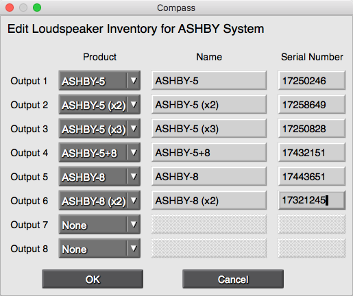
Edit Loudspeaker Inventory dialog in Compass
Enter a name and the number of loudspeakers looped on each channel.
Click OK to save and upload the MPS-488HP loud- speaker inventory.
Once the MPS-488HP is added to an RMS page, the device container can display channel labels with simple device status or a full meter bar display along with a detailed text view showing voltage and current draw for the connected Ashby loudspeakers.
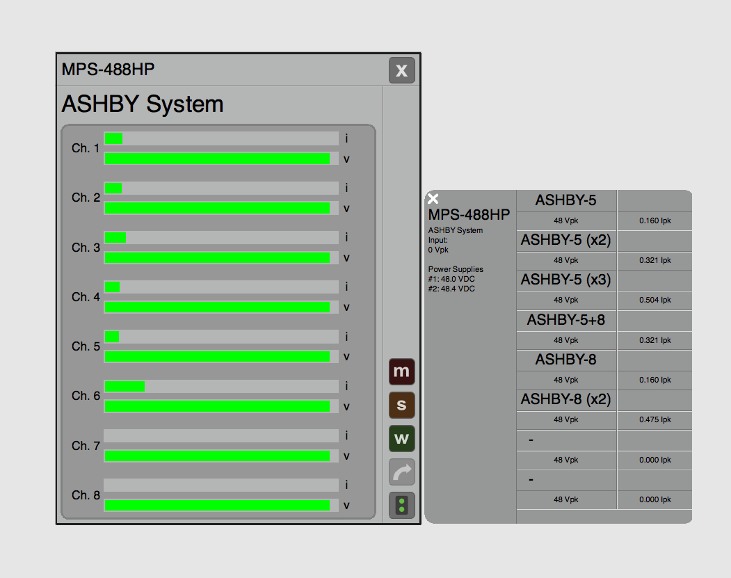
Voltage and current draw for connected loudspeakers in Compass
Caution
Disconnect the mains plug or power off the MPS-488HP before disconnecting its power cord.