Overview
Select a device from the Processors View (Device Icon is at far left) by touching a Discovered Device.
One device can be selected at a time. A green circle indicates the device is connected; a red rectangle indi- cates it is not connected.
Overview
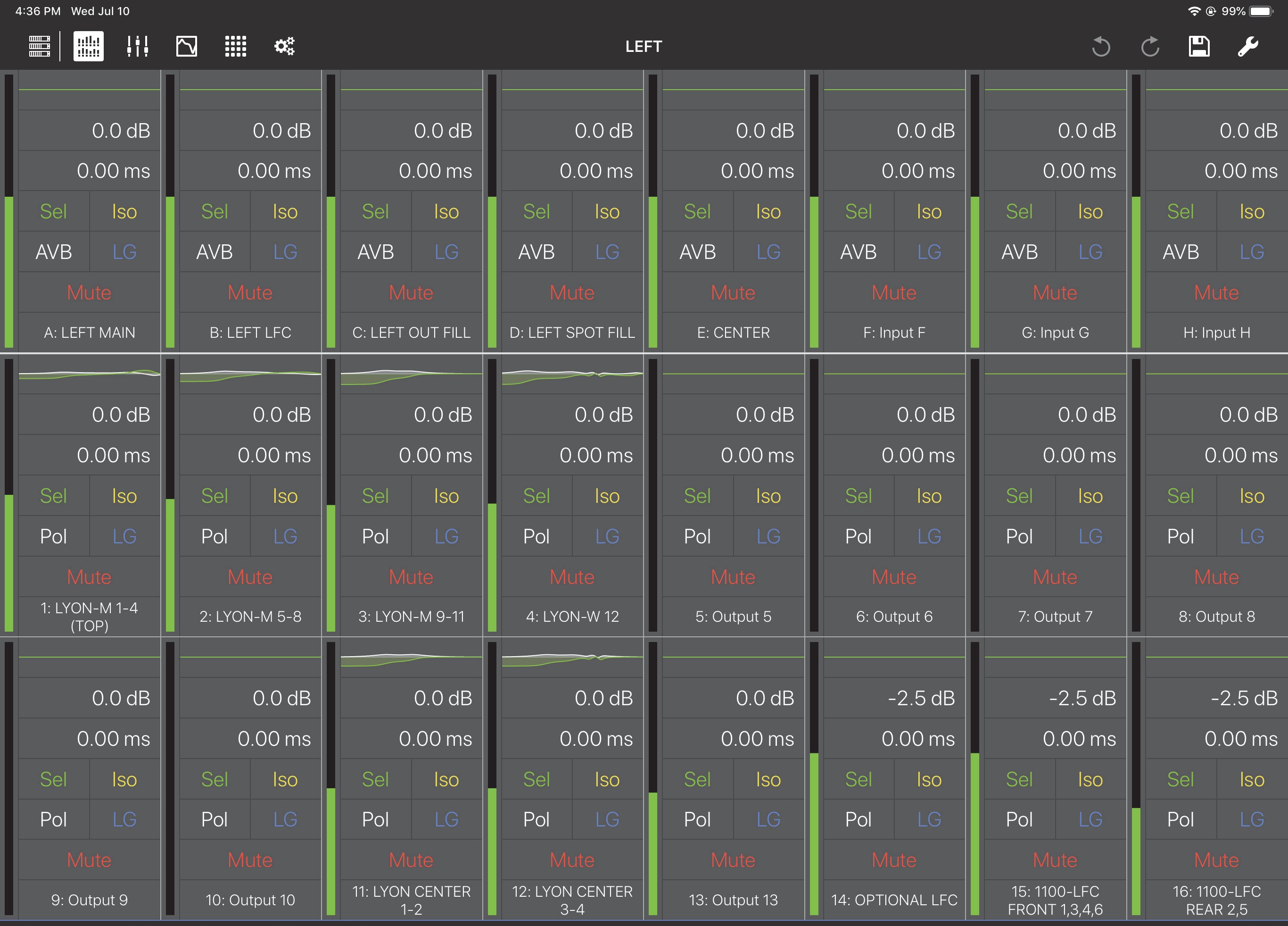
To display the Overview from any other Compass Go view, tap the Overview Icon (highlighted in the figure above) in the top menu bar.
The view is organized into one row of inputs, and two rows of outputs:
Inputs A–H (GALAXY) and Inputs A–F (Galileo and Callisto) are on the top row.
Outputs 1–8 are on the middle row.
Outputs 9–16 are on the bottom row.
Each input/output channel has a meter showing its input/output level.
Each channel control is discussed below.
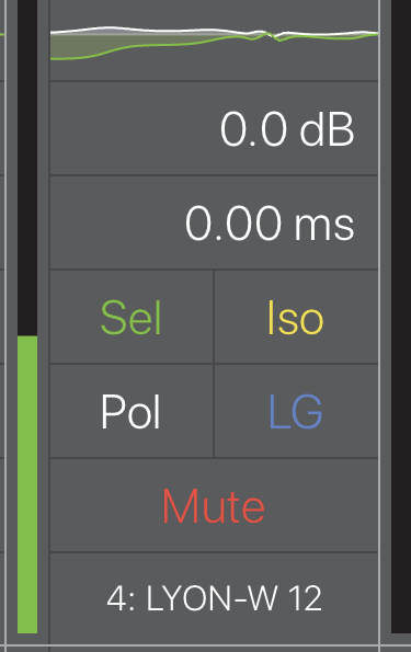
Channel detail
EQ curve
At the top of the channel, the EQ Curve is located in a small rectangle. Tapping the EQ curve displays the EQ view for that channel (see Chapter 5: EQ View).
Gain settings
Tap the gain value.
Drag up/down to increase/decrease the value. The gain can be in the range -90 dB to +10 dB.
A blue rectangle surrounds the gain value.
- OR -
Double-tap the gain value. A numeric pad opens.
A numeric pad opens.
Enter a new gain setting.
The +/- button toggles between positive and negative values.
Note that when no sign is shown, the value is interpreted as negative.
Touch Done when finished.
Delay settings
Double-tap the delay value (below the Gain field).
A numeric pad opens.
Enter a delay amount.
Tap Delay Unit to choose a unit from the following options:
milliseconds, feet, meters, frames (24 fps, 25 fps, 30 fps) samples (96 kHz).
Tap Back to return to the Delay setting numeric pad.
Tap Done when finished.
- OR -
Single-tap the delay value.
A blue rectangle surrounds it.
Touch and drag up/down to increase/decrease the delay.
The maximum delay is 2000 ms for outputs, and 500 ms for inputs.
Sel/Iso/mute status
Sel/Iso/Mute controls all work the same. Each shows its active state with a solid colored rectangle surrounding it. Touch a control to toggle its value.
Polarity (POL)
POL controls the polarity of the signal. When active, the polarity is reversed.
Link groups (LG)
Use Link Groups to edit and control multiple channels simultaneously. Assign a channel to the desired Link Group. Touch the On/Off switch to enable/disable a Link Group.
Channel name
The default channel name is derived from its input/output channel number, but can be edited. To assign a name to the channel:
Double-tap the channel name.
The Edit Channel Name dialog opens.
Use the iPad keyboard to enter a new name.
Touch Done when finished.
Overview tools
Tap the Tools icon at the top-right of the Overview to open the following dialog:
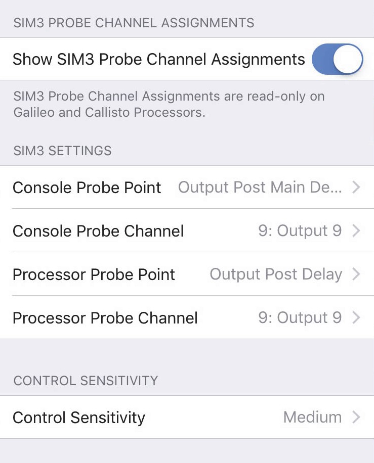
Tools options from Overview
Show SIM3 probe channel assignments
Touch and drag the button to the right to show the SIM3 Probe Channel Assignment fields on the Overview.
Touch and drag the button to the left to conceal the SIM3 Probe Channel Assignment fields from displaying on the Overview.
SIM3 settings
The current SIM3 Probe Point and Channel Settings are displayed. Touch any of them to open their assignment options.
When Show SIM3 Probe Channel Assignments is active, you can change the Console and Probe Channel assignments on the Overview by touching the C or P fields, respectively, on the desired cells.
The current SIM3 console and probe assignments determine which input and/or outputs display these assign- ment fields.
If the Processor Probe Point is set for one of the output options, a P field appears only in the output cells.
If the Console Probe Point is set for one of the output options, a C field appears only in the output cells.
If the Processor Probe Point is set for one of the input options, a P field appears only in the input cells.
If the Console Probe Point is set for one of the input options, a C field appears only in the input cells. To assign a new channel to either probe point, touch a different channel’s C or P field.
The figure below shows the Console Probe Channel set to Input C, and the Processor Probe Channel set to Output 3.
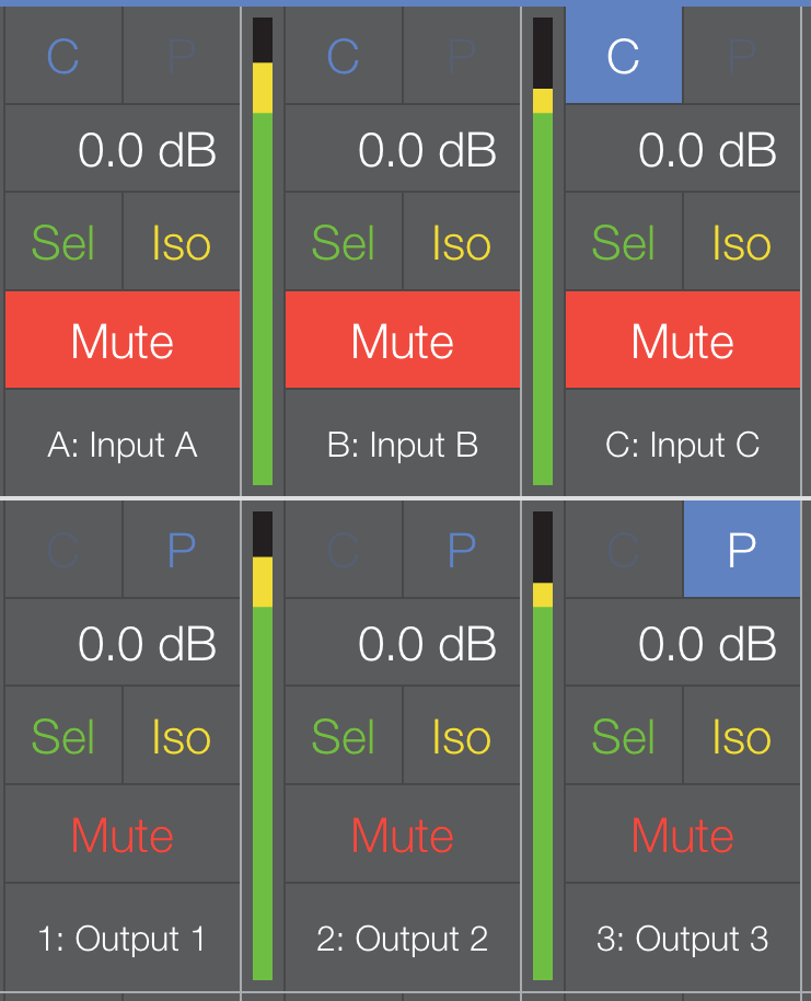
SIM3 Probe Point Assignments on the Overview
Note
The field to the left of the highlighted P for Output 3 is gray (inactive) to signify that the Console Probe Point is set to an input. The Console and Processor Probe Point types can only be changed from the Tools menu or the Settings View (see page 57).
Control sensitivity
This sets the sensitivity for Compass Go’s touch controls.
Touch the current setting and choose Low, Medium, or High (default). High sensitivity causes the fastest change in value per distance dragged.
Snapshot tool
Tap the Disk icon at the top-right of any of the active device views to open the following dialog:
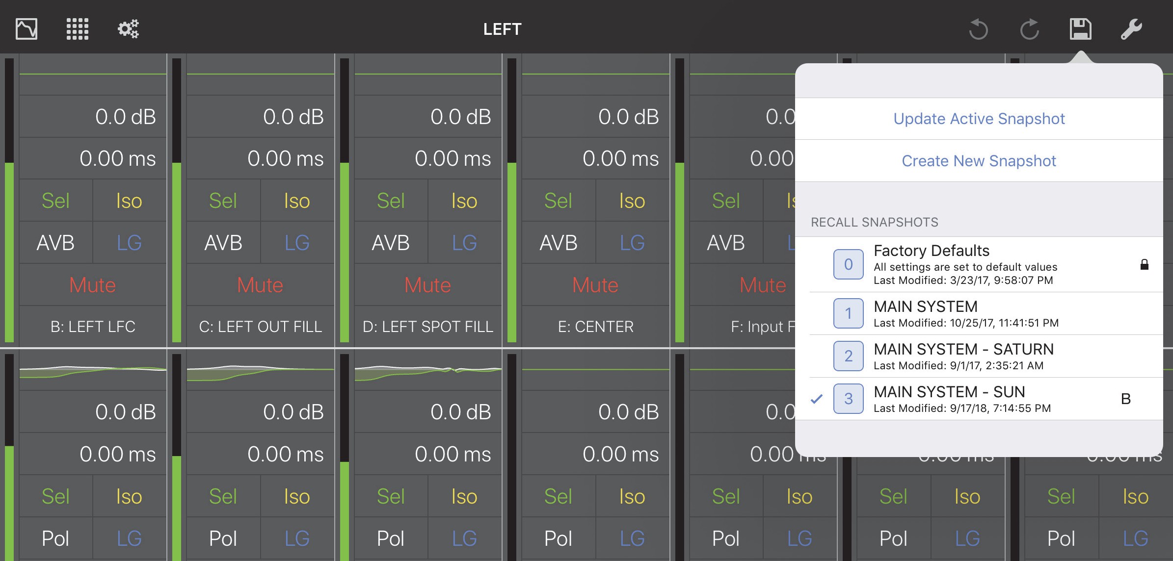
Snapshot options from the Overview
Update active snapshot
Touch Update Active Snapshot to use the current settings to update the currently active Snapshot.
Create new snapshot
Touch Create New Snapshot to use the current settings to create a new Snapshot.