Block Diagram & Signal Flow for IntelligentDC Systems
The block diagram shown in the figure below is a simplified view of the signal paths between the MPS-488HP power supply and the IntelligentDC loudspeaker. Audio signal is applied via XLR to any of the power supply’s 8 inputs. Multiple outputs can be linked together for convenience via the input link switches. The audio signal and DC voltage is then sent to the loudspeaker on a single 5 conductor cable, whose terminations are dependent on both the IntelligentDC Power Supply version you have, as well as the input board type of your IntelligentDC loudspeaker.
Note
The MPS-482HP has similar internal resistance values. However, it has only two input channels and two output channels. Input signals can be received via either XLR or Phoenix connectors, but not both for the same channel at the same time.
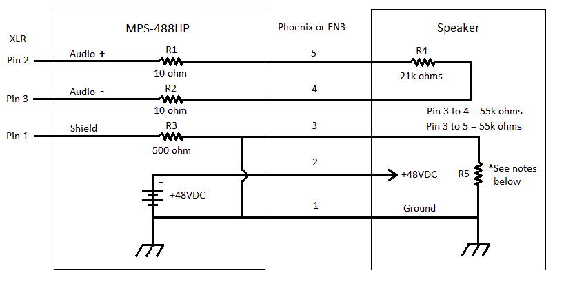
Power Supply to Loudspeaker Signal Flow Block Diagram
R5 is 1 kΩ or less
R1 and R2 are 50 Ω if the power supply was manufactured in 2014 or earlier, and 10 Ω thereafter.