Amplification and Audio
The 900-LFC’s drivers are powered by a proprietary two-channel, open-loop, class D amplifier. The audio signal is processed with correction filters for flat phase and frequency responses and by driver protection circuitry. Each channel has peak and rms limiters that prevent driver over-excursion and regulate voice coil temperatures.
The 900-LFC user panel (shown in the figure below) includes Input and Loop output connectors for audio, Limit and Active LEDs, and RMS connectors and controls (see RMS Remote Monitoring System).
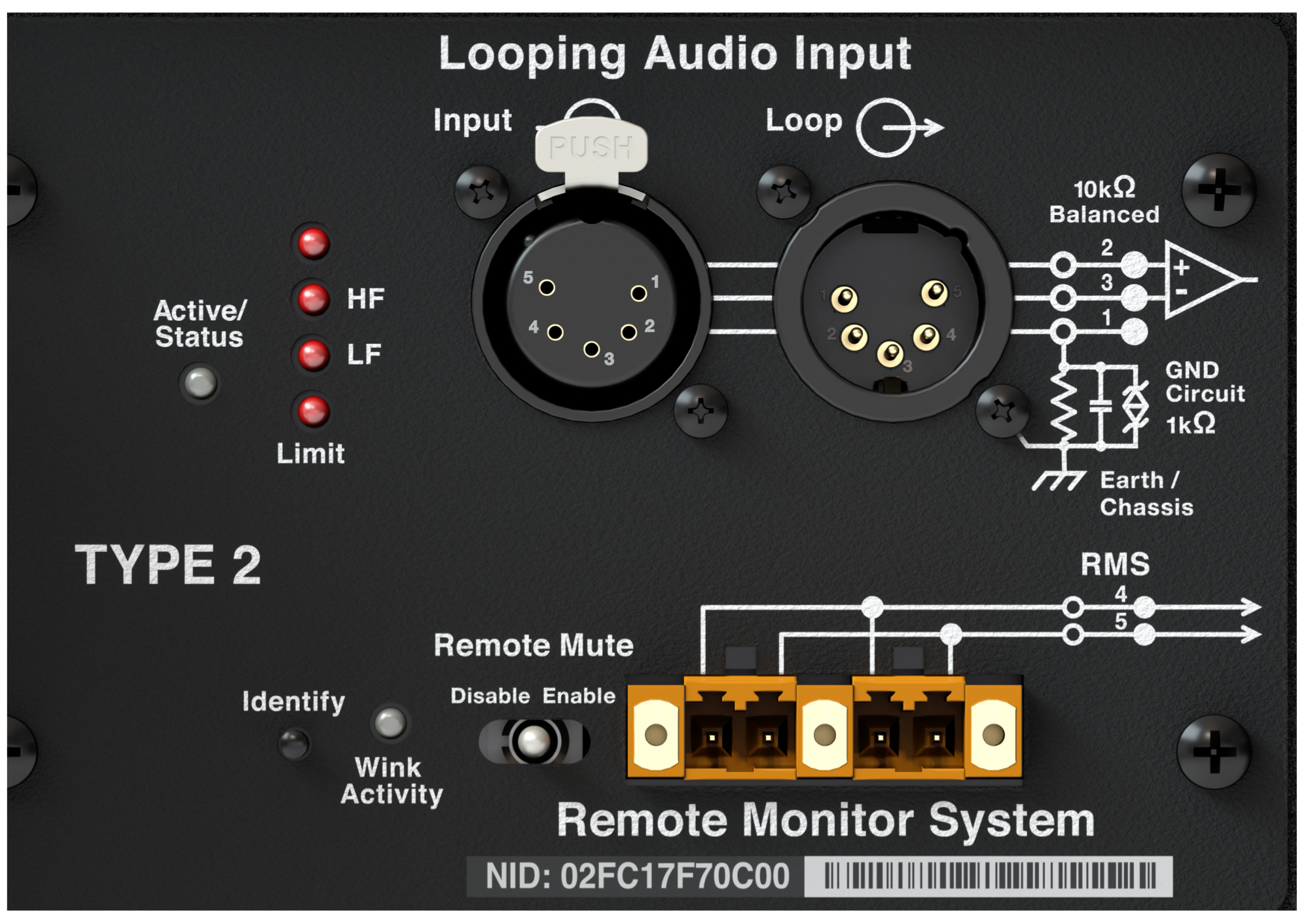
900-LFC User Panel
Audio Connectors
The 900-LFC is available with XLR 3-pin, as shown in the first figure below, or 5-pin connectors, shown in the second figure, for audio Input and audio Loop output. XLR 5-pin connectors accommodate both balanced audio and RMS signals.
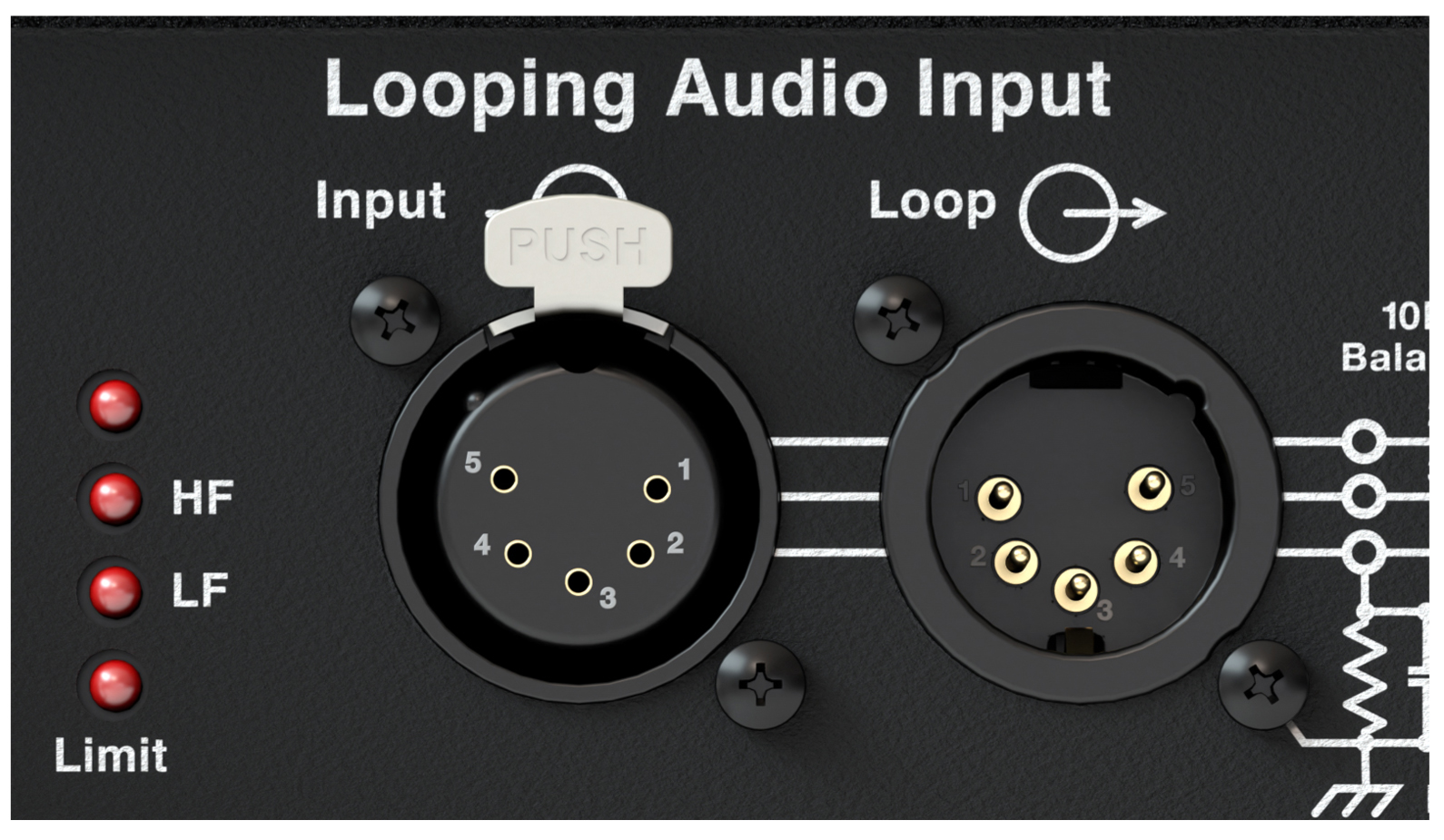
XLR 5-Pin Audio Connectors, Input and Loop Output
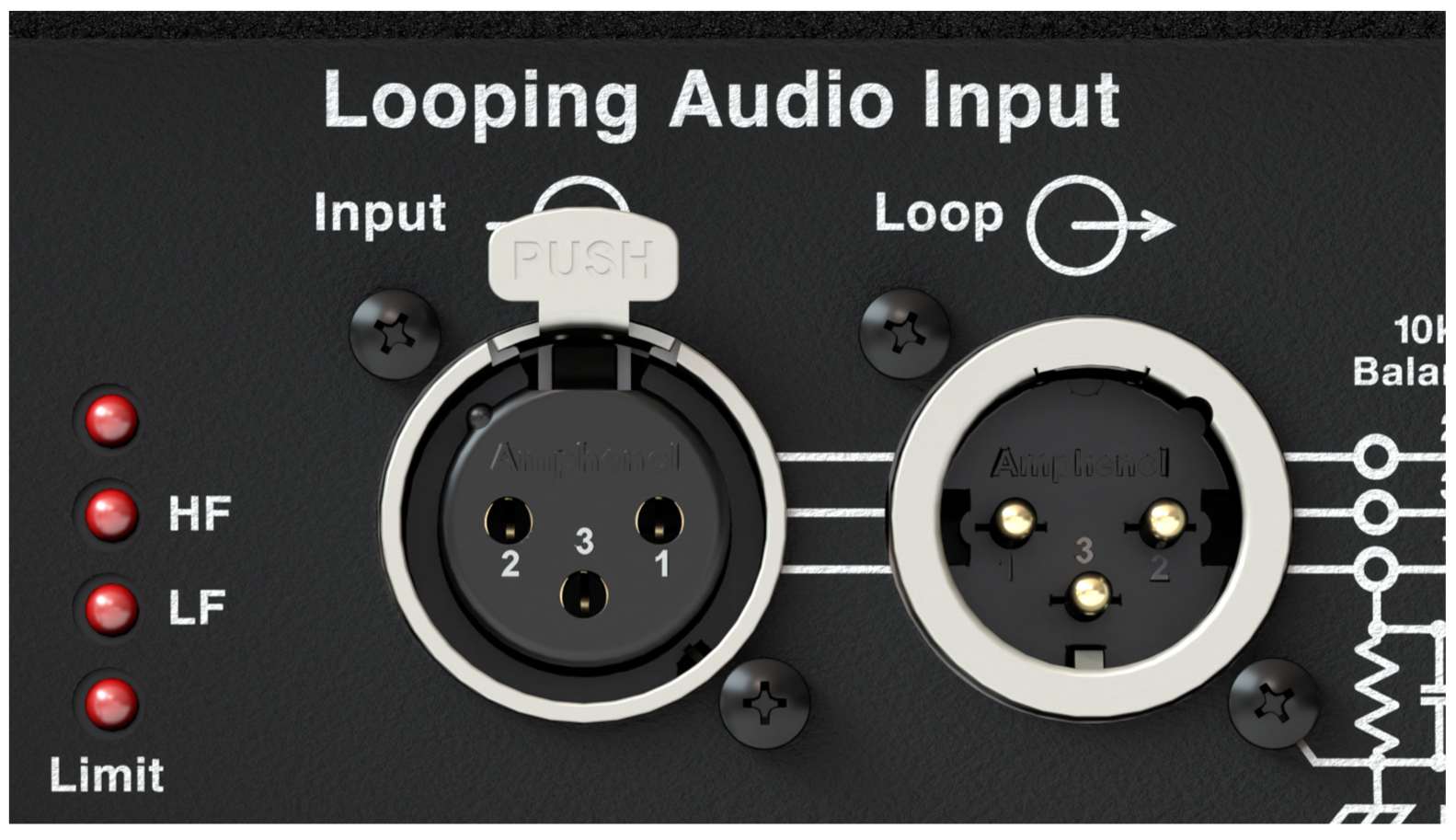
XLR 3-Pin Audio Connectors, Input and Loop Output
Audio Input (XLR 3-Pin or 5-Pin Female)
The XLR 3-pin or 5-pin female Input connector accepts balanced audio signals with an input impedance of 10 kOhm. The connector uses the following wiring scheme:
Pin 1 — 1 kOhm to chassis and earth ground (ESD clamped)
Pin 2 — Signal (+)
Pin 3 — Signal (–)
Pin 4 — RMS (polarity insensitive)
Pin 5 — RMS (polarity insensitive)
Case — Earth (AC) ground and chassis
Note
Pins 4 and 5 (RMS) are included only with XLR 5-pin connectors.
Pins 2 and 3 carry the input as a differential signal. Pin 1 is connected to earth through a 1 kOhm, 1000 pF, 15 V clamped network. This circuitry provides virtual ground lift for audio frequencies while allowing unwanted signals to bleed to ground. Make sure to use balanced XLR audio cables with pins 1–3 connected on both ends. Telescopic grounding is not recommended and shorting an input connector pin to the case may cause a ground loop, resulting in hum.
Tip
If unwanted noise or hiss is produced by the loudspeaker, disconnect its input cable. If the noise stops, there is most likely nothing wrong with the loudspeaker. To locate the source of the noise, check the audio cable, source audio, AC power, and electrical ground.
Audio Loop Output (XLR 3-Pin or 5-Pin Male)
The XLR 3-pin or 5-pin male Loop output connector allows multiple loudspeakers to be looped from a single audio source. The Loop output connector uses the same wiring scheme as the Input connector (see Audio Input (XLR 3-Pin or 5-Pin Female)). For applications that require multiple 900-LFCs, connect the Loop output of the first loudspeaker to the Input of the second loudspeaker, and so forth.
Note
The Loop output connector is wired in parallel to the Input connector and transmits the unbuffered source signal even when the loudspeaker is powered off.
Calculating Load Impedance for Looped Audio Signals
To avoid distortion when looping multiple loudspeakers, make sure the source device can drive the total load impedance of the looped loudspeakers. In addition, the source device must be capable of delivering approximately 20 dBV (10 V rms into 600 ohms) to yield the maximum SPL over the operating bandwidth of the loudspeakers.
To calculate the load impedance for the looped loudspeakers, divide 10 kOhms (the input impedance for a single loudspeaker) by the number of looped loudspeakers. For example, the load impedance for ten 900-LFCs is 1000 ohms (10 kOhms / 10). To drive this number of looped loudspeakers, the source device should have an output impedance of 100 ohms or less. This same rule applies when looping 900-LFCs with other Meyer Sound self-powered loudspeakers.
Note
Most source devices are capable of driving loads no less than 10 times their output impedance.
Tip
Audio outputs from Meyer Sound’s Galileo GALAXY Network Platform have an output impedance of 50 ohms. Each output can drive up to 20 Meyer Sound (10 kOhm) loudspeakers without distortion.
Caution
Make sure that all cabling for looped loudspeakers is wired correctly (Pin 1 to Pin 1, Pin 2 to Pin 2, and so forth) to prevent the polarity from being reversed. If one or more loudspeakers in a system have reversed polarity, frequency response and coverage will be significantly degraded.
Cable Rings
Two cable rings are provided on the rear of the 900-LFC cabinet (Figure 15). Power and audio cables should be tied off to the rings to reduce strain on the cables and prevent damage to them during installation. The cable rings should not be used for any other purpose.
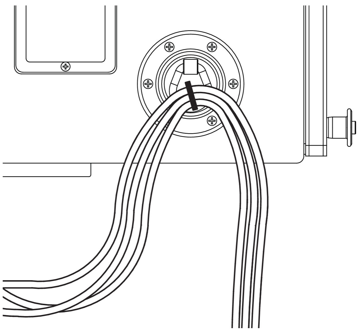
Cables Tied Off to Cable Ring
Caution
900-LFC cable rings should only be used to reduce strain on cables. The cable rings should not be used for any other purpose.
TruPower Limiting
The 900-LFC employs Meyer Sound’s advanced TruPower® limiting. Conventional limiters assume a constant loudspeaker impedance and set the limiting threshold by measuring voltage alone. This method is inaccurate because loudspeaker impedances change as frequency content in the source material changes, and as thermal values for the loudspeaker’s voice coil and magnet vary. Consequently, conventional limiters often begin limiting prematurely, which reduces system headroom and dynamic range.
In contrast, TruPower limiting anticipates varying loudspeaker impedances by measuring both current and voltage to compute the actual power dissipation in the voice coil. This approach improves performance, both before and during limiting, by allowing the driver to produce the maximum SPL across its entire frequency range, while also retaining signal peaks. TruPower limiting also eliminates power compression at high levels over lengthy periods, which helps regulate voice coil temperatures, thereby extending the life of the driver.
LF Limit LED
The low-frequency driver for the 900-LFC is powered by separate amplifier channels, one for each voice coil, that are routed to a single limiter. When a safe power level is exceeded in either channel, limiting is engaged for both channels and the LF Limit LED lights on the user panel (the HF Limit LED is disabled for the 900-LFC), as shown in the figure below..
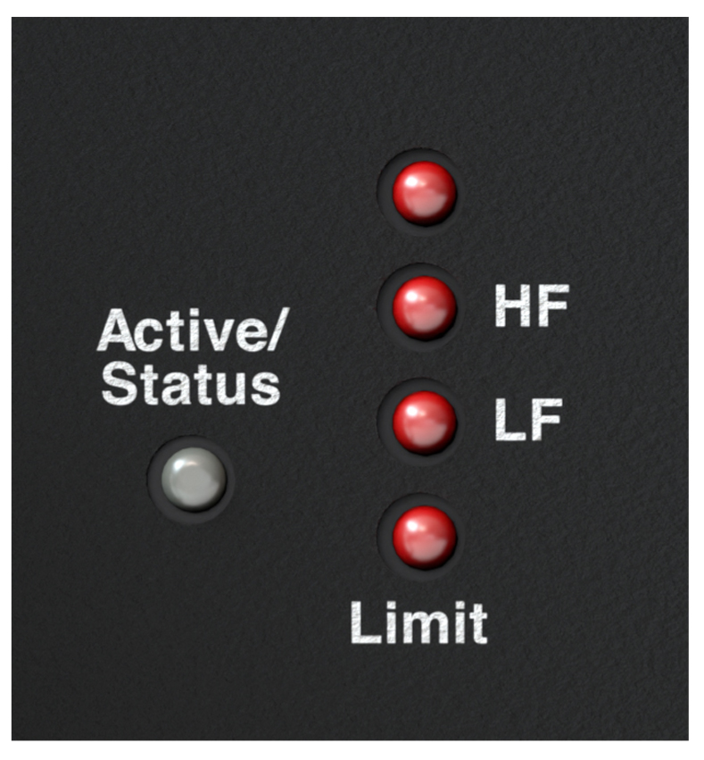
900-LFC Limit LEDs (HF LED Disabled)
When engaged, the limiter not only protects the drivers but also prevents signal peaks from causing excessive distortion in the amplifier channels, thereby preserving headroom and maintaining smooth frequency response at high levels. When levels return to normal, below the limiter threshold, limiting ceases.
The 900-LFC performs within its acoustical specifications at normal temperatures when the LF Limit LED is unlit, or when the LED is lit for 2 seconds or less and then turns off for at least 1 second. If the LED remains lit for longer than
3 seconds, the loudspeaker enters hard limiting where:
Increases to the input level have no effect
Distortion increases due to clipping
Drivers are subjected to excessive heat and excursion, thereby compromising their lifespan
Caution
The Limit LED indicates when a safe, optimum level is exceeded. If a 900-LFC loudspeaker system begins to limit before reaching the desired SPL, consider adding more loudspeakers to the system.
Amplifier Cooling System
The 900-LFC is convection cooled. The amplifier’s heat sink provides natural convection cooling from the air flowing near its fins. When exposed to high ambient temperatures or when driven continuously at high output levels, a variable-speed fan circulates air internally to ensure that the 900-LFC remains operational.
Caution
To keep the 900-LFC from overheating, allow at least 6 inches behind the cabinet for proper ventilation.
The 900-LFC’s heat sink can reach temperatures up to 80 °C (176 °F) during extreme operation. Wait 15 minutes for the loudspeaker to cool before touching.
Active/Status LED
During normal operation, when the 900-LFC is powered on, the Active/Status LED is solid green. If the loudspeaker encounters a hardware fault, or the loudspeaker begins to overheat, the LED flashes red. In some instances, the loudspeaker will continue to output audio while the LED flashes red, though with a reduction in the limiter threshold and acoustic output to protect the loudspeaker.
If a loudspeaker is overheating (for RMS-equipped loudspeakers, you can verify this situation in Compass RMS), a reduction in SPL may be necessary. If, after a reduction in SPL and an appropriate cooling period, the Active/Status LED continues to flash red (does not return to solid green), contact Meyer Sound Technical Support.
If the Active/Status LED flashes red and the loudspeaker does not output audio, contact Meyer Sound Technical Support immediately.
Caution
If a 900-LFC loudspeaker system consistently overheats before reaching the desired SPL, consider adding more loudspeakers to the system.
Note
During startup, the Active/Status LED flashes multiple colors successively. For more information about the power on sequence, see Intelligent AC Power Supply.
Tip
When the 900-LFC is connected to an RMS network, the Compass RMS software provides additional feedback on the loudspeaker’s hardware status and operating temperature. For more information, RMS Remote Monitoring System.