RMS Remote Monitoring System (optional)
An optional RMS communication module can be installed in the UPM-1P and UPM-2P loudspeakers' lower module slot.
RMS is a real-time networked monitoring system that connects Meyer Sound self-powered loudspeakers with a Windows-based PC at the sound mix position or other desired remote location. Optional RMS software delivers extensive status and system performance data directly to you from every installed loudspeaker.
RMS allows you to monitor amplifier voltages, limiting activity, power output, temperature, fan and driver status, warning alerts, and other key data for up to 62 loudspeakers without a network repeater; data is updated two to five times per second.
Note
Optional Loudspeaker Mute and Solo functions, helpful for acoustic setup or troubleshooting, are also available. A jumper must be installed in the RMS communication module in order to enable Mute and/or Solo functionality; the software also needs to be enabled for these functions. When fitted with an RMS communication module, the loudspeaker is shipped with these functions disabled. Once the RMS jumper(s) are installed, muting can still be disabled to eliminate any chance of an operator error (a muting error, for example) during a performance. Both functions can be controlled by software commands. Also, note that RMS does not control AC power.
As shown in the figure below, loudspeakers are identified on the network by Node Names assigned during a one-time “commission” into the RMS database that resides on the host computer (as a part of the software).
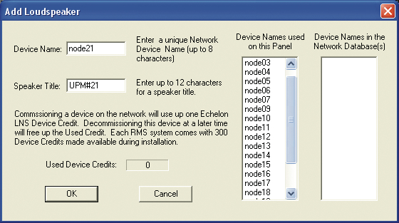
Commissioning a loudspeaker using RMS
This information is permanently stored on each RMS communication module and in the RMS database unless you modify it. Speaker Titles can be modified at any time, allowing you to customize how you view the data.
In addition, any loudspeaker can be physically identified from RMS software by activating the Wink function – a Wink LED will turn on the RMS communication board that corresponds to its Node Name.
A loudspeaker is identified using the RMS software by activating the “service” function; an icon will show up on the RMS screen corresponding to its Node Name, as shown in the figure below. This makes verifying Speaker Titles and speaker field labels easy, using the Wink or Service Button commands.
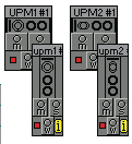
RMS loudspeaker icons
Note
If the loudspeaker’s amplifier heatsink temperature exceeds 75° C (167° F), the loudspeaker's user panel On/Temp LED will turn red, while the loudspeaker icon in the RMS host software will respond by displaying yellow — indicating that the loudspeaker is running hot, but still within safe operating limits. If the LED in the RMS host software changes to red, then the UPM- 1P/UPM-2P is operating above its 100º C (212° F) maximum safe operating temperature. Check to ensure that the cabinet is properly ventilated and/ or decrease the loudspeaker’s audio output signal immediately.
Understanding the RMS User Panel
The RMS section of the user panel has three LEDs and two buttons, as shown in the figure below.
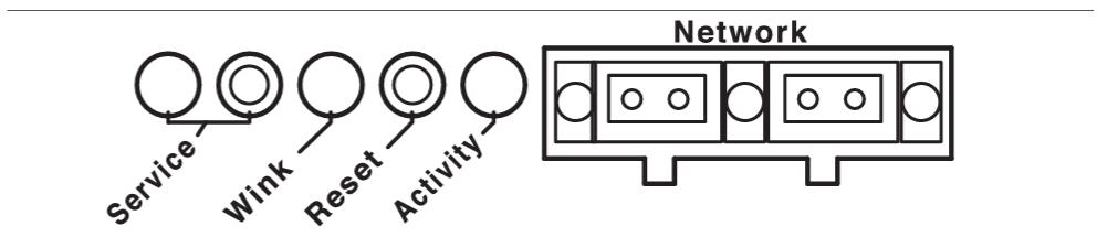
RMS section of the user panel
The following sections describe their functions.
Service LED (Red)
When blinking once every two seconds, the Service LED indicates that the network hardware is operational, but the loudspeaker is not installed (commissioned) on the network. When a loudspeaker has been installed on the network the Service LED will be unlit and the Activity LED will flash continuously.
Note
When continuously lit, the Service LED indicates that the loudspeaker has had a local RMS hardware failure. In this case, the RMS communication module may be damaged and you should contact Meyer Sound Technical Support.
Service Button
Pressing the Service button will display an indicator on the corresponding loudspeaker display icon on the RMS screen. Press and hold both the Service and the Reset buttons to decommission the communications module will from the network. The red Service LED will blink.
Wink LED (green)
When lit, the Wink LED indicates that an ID signal has been sent from the host station computer to the loudspeaker. This is accomplished using the Wink button on the loudspeaker Icon, Meter or Text views in the RMS monitoring program.
Reset Button
Pressing the Reset button will cause the firmware code within the RMS card to reboot. However, the commissioning state of the communications module will not change (this is stored in flash memory). When used in combination with the Service button, the communications module will be decommissioned from the network and the red Service LED will blink.
Activity LED (Green)
When the loudspeaker has been commissioned the Activity LED will flash continuously. When the Activity LED is unlit (and the red LED is blinking) the loudspeaker has not been installed on the network.
Note
The LEDs and buttons on the RMS section of the user panel are used exclusively by RMS, and have no effect on the acoustical and/or electrical activity of the loudspeaker itself – unless Mute or Solo is enabled at the module and from the RMS software.
User Interface
The optional RMS software features an intuitive, graphical user interface. As mentioned earlier, each loudspeaker appears on your computer monitor as a “view” in the form of a status icon, bar graph meter, or text meter (numerical values), depending on your preferences.
Each view contains loudspeaker identification information and data from the amplifier, controller, drivers and power supply of that particular unit. System status conditions cause changes in icon and bar graph indicators, alerting the operator to faults or excessive levels. The views are moveable and are typically arranged on the screen to reflect the physical layout of the loudspeakers. You can design a screen “panel” of icons or meters, as shown in the figure below, and save it on your hard disk, with the panel conveniently named for a unique arrangement or performance.
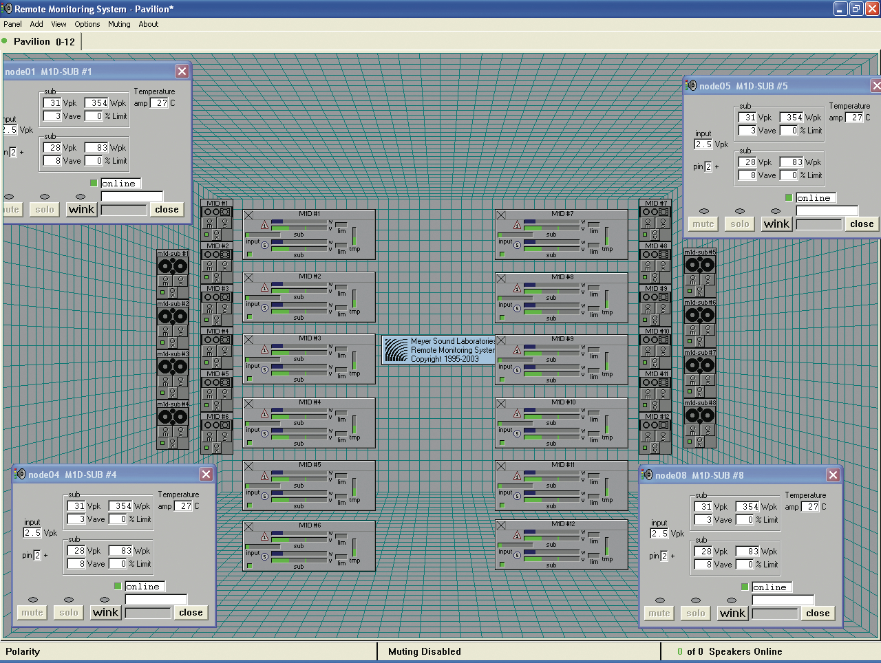
Sample RMS display panel
If the loudspeaker installation pattern changes completely, a new screen panel can be built. If a different subset of already installed loudspeakers will be used for a subsequent show, only selected loudspeakers need to appear on the monitoring screen for that performance.