Mixer configuration
This section introduces the concept of D-Mitri mixer configuration. It describes what a mixer configuration is, and shows how to create a configuration that can quickly connect CueStation to an actual or virtual D-Mitri system.
CueStation has been designed to make the configuration as transparent as possible after the initial setup. When using CueStation with a configured system, you never have to worry about which channel is on which module, or about routing signal from one D-Mitri module to another. The entire system works as a unit.
Configuring a D-Mitri system
CueStation’s Mixer Configuration is a digital representation of all modules in a D-Mitri system. Every time the D-Mitri system is turned on or power cycled, it must receive a valid configuration before audio can be processed.
The number of D-Mitri modules in the system
The type and number of modules available
VLAN IDs and Switch Port settings
The number of buses, bus assigns, and VGroups For each I/O module:
The range of channels used by the module, and in some cases, the type of channels
The host DCP module
A valid configuration never duplicates channel numbers per channel type (e.g., two inputs cannot be simultaneously mapped to channel 10). A configuration can be loaded automatically at power on if a project is saved to flash memory. A configuration can also be sent from a CueStation client as part of a project file.
If one D-Mitri module within a larger system goes offline, the configuration is automatically re-sent to Processor modules once the system has reconnected.
The following section describes how to configure the system using the Mixer Configuration window.
Connecting to the D-Mitri system
You can try your hand at conducting a bit of simple mixer configuration by connecting to a D-Mitri system or to VirtualD-Mitri. Follow these steps to make the connection:
Connect your CueStation client computer to the D-Mitri control network.
In CueStation, choose Network > Connect to open the Connection Manager window.
Select a D-Mitri system (or VirtualD-Mitri) from the list, and click Connect (all windows).
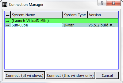
Connection Manager Window
Tip
To quickly connect individual CueStation windows to a D-Mitri system, system names can be dragged from the Connection Manager window onto any other CueStation window.
CueStation connects to the selected D-Mitri system, or to VirtualD-Mitri, which emulates a D-Mitri system. CueStation window title bars reflect the name of the connected system.
Configurations in D-Mitri flash memory
Meyer Sound provides a configuration file for your system that is stored in the flash memory of system Processor modules.
Open CueStation.
Choose Network > Connect. Select your system from the list, then click Connect (all windows).
Choose Windows > Mixer Configuration to open the Mixer Configuration window. If you are running CueStation for the first time, the Mixer Configuration window opens by default.
Choose Projects > Open Project from Flash.
Enable the Load Project and Send Configuration options, then click Open. CueStation loads the configuration stored in the Processor module flash memory and sends the configuration to the D-Mitri system.
Verify that the GNet Switch port settings in the System Configuration pane match the system diagram provided by Meyer Sound.
Choose Projects > Save Project As to save a copy of your configuration to the computer running CueStation.
If you are working offline with VirtualD-Mitri, hardware must be added manually.
Manually configuring modules
Open CueStation, then connect to the system you are configuring.
Choose Windows > Mixer Configuration to open the Mixer Configuration window. If you are running CueStation for the first time, the Mixer Configuration window is the window that first appears when CueStation opens.
Instruct CueStation to detect what hardware is installed.
Configuration > Query Hardware for Configuration populates the System Configuration pane with all modules detected in the D-Mitri system. Query Hardware for Configuration does not detect I/O modules that are not part of the active configuration.
The Auto-Setup button configures all detected I/O points to default.
If CueStation is connected to VirtualD-Mitri, modules must be added to the project by choosing Modules > New Module.
Tip
Modules can also be added to the configuration by dragging entries from the Module Types pane into the System Configuration pane.
An alert is displayed if the selected configuration does not match the active configuration. Click Details for more information about the differences between configurations.
Sending a Configuration to a D-Mitri System
Click Send Config in the upper right corner of the Mixer Configuration window to send a completed configuration to the D-Mitri system. A D-Mitri configuration does not take effect until you send it to the modules in your system.
CueStation posts a notification in its Log window that the configuration has been sent. If the system is running a configuration that has previously generated warnings, the System Status icon displays a warning to indicate a problematic configuration. The CueStation mixer window shows faders and other controls corresponding to the configuration.
Project title
Projects are assigned titles that display in the CueStation windows. Project titles are independent of dmitriProject file names.
Choose Projects > Set Project Title.
Enter a new title.
Press Enter or click OK.
Mixer Configuration window
The Mixer Configuration window features three tabs: Modules, Aliases, and Event Triggers.
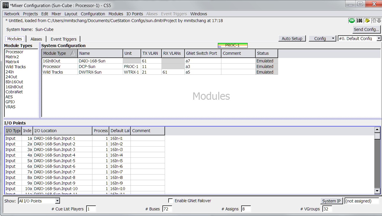
Mixer Configuration Window, Modules Tab
Though most of the information the Mixer Configuration window provides is specific to each of the tabs, the window does offer several persistent controls in the border areas outside the tab fields, as described in the following table.
Control | Description |
|---|---|
Send Config button | Sends the current Mixer Window configuration to CueStation. |
Config button menu | A pull-down menu containing the following functions: New Config, Rename Config, Duplicate Config, Delete Config, Set Config ID, Lock Config, Unlock Config. |
Show | Filters view by I/O point type (All, Input, PAFL, etc.). |
# Cue List Players | Enter the total number of cue list players here. |
# buses | Enter the total number of buses here. |
# Assigns | Enter the total number of bus assigns here. |
# VGroups | Enter the amount of virtual groups here. |
System IP | You can enter an IP address for the system in this text field. Pressing the System IP button itself opens the System IP Config dialog, with fields for IP Address, Netmask, and Gateway. |
Enable GNet Failover | Enables use of the secondary Ethernet audio network connection of D-Mitri modules (AVB 2). |
Modules tab
The Modules tab of the Mixer Configuration window displays three separate panels; Module Types, System Configuration information, and I/O Points.
The Module Types list contains a list of D-Mitri module types. To add a specific module type to your configuration, you can drag a module type name from the list into the adjacent System Configuration table.
The System Configuration table in the Modules tab displays the modules in your configuration and displays each module’s networking configuration. The System Configuration table contains the following default columns.
Field | Description |
|---|---|
Processing Gauge | Displays a visual graph of the allocated resources for each DCP: |
Green indicates the allocated inputs. Orange indicates the allocated buses. Purple indicates the allocated outputs. | |
Module Type | The Module Type is shown when an entry is created. Must match the physical module for the configuration to work properly. |
Name | Displays the module name. Module Name must match the name programmed into the module. |
Unit | Automatically assigned unit name to distinguish between multiple processing units. Value can be changed. |
TX VLAN | Provides a field for you to enter the selected module’s GNet transmission VLAN. |
RX VLANs | Provides a field for you to set the selected module’s GNet reception VLANs. |
GNet Switch Port | Provides a field for you to set the selected module’s GNet Switch Port. |
Comment | Provides an area for you to enter text comments about a module. |
Status | Displays module status. Values are Emulated, Online, or Offline. |
The I/O Points table in the Modules tab displays the input and output information for each module in the chosen D-Mitri system. I/O Points that lack corresponding modules in the Modules table are highlighted in red.
The I/O Points table contains the following default columns.
Field | Description |
|---|---|
I/O Type | The type of the I/O point is automatically assigned during configuration. |
Index | The index number of the I/O point is automatically assigned during configuration. |
I/O Location | The location of the I/O point is automatically assigned during configuration. |
Processor | Shows a number from 1–4 to indicate which DCP processes the I/O point. |
Default Label | Provides a field for you to set the selected module’s GNet reception VLANs. |
Comment | Provides an area for you to enter text comments about a module. |
Default Label | The default label of the I/O point is automatically assigned during configuration. |
CueStation’s Mixer Config window provides a Fill Down function for Modules and I/O Points column values.
Select a range of entries in the Modules tab or I/O Points tab.
Right-click in a column and choose Fill Down Selected.
In the Specify Initial Default Label dialog, enter a value or comment.
Press Enter or click OK.
Each selected item changes to sequentially follow the initial entry.
The contextual menu for the Default Label column also provides an option to reset a selection of label values to their defaults.
Note
When manually editing fields, invalid entries are highlighted in pink. Attempting to send invalid configurations results in a Mixer Configuration warning.
The Modules List displays D-Mitri modules of all connected systems, using a [System- Name.ModuleName] syntax.
Finally, the Modules tab also shows an Auto Setup button, which configures the Mixer Configuration window to the current hardware or virtual setup.
Aliases tab
The Mixer Configuration window’s Aliases tab displays a list of network address alias definitions for modules in the D-Mitri system. These aliases enable you to refer to D-Mitri modules and command strings in CueStation by custom names.
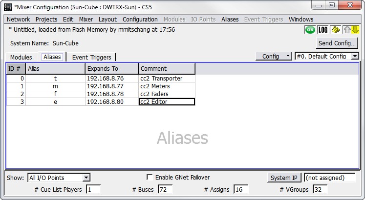
Mixer Configuration Window, Aliases Tab
The Aliases tab in the Mixer Configuration window displays a table containing the following default columns.
Field | Description |
|---|---|
ID # | The Alias ID number: assigned automatically when the alias is created, but can be changed. |
Alias | Alias name: assigned automatically when the alias is created, but can be changed. |
Expands To | Enter the IP address or command string that is associated with the alias. To expand an alias to multiple values, separate the values with a comma. |
Comment | Provides an area to enter text comments. |
Event Triggers tab
The Mixer Configuration window’s Event Triggers tab provides a place for you to define and view Event Triggers. Event Triggers specify how the D-Mitri system should respond to incoming event strings, such as MIDI messages. Event Triggers defined in the Event Triggers tab become active when you send the system configuration to the D-Mitri system using the Mixer Configuration window’s Send Config button.
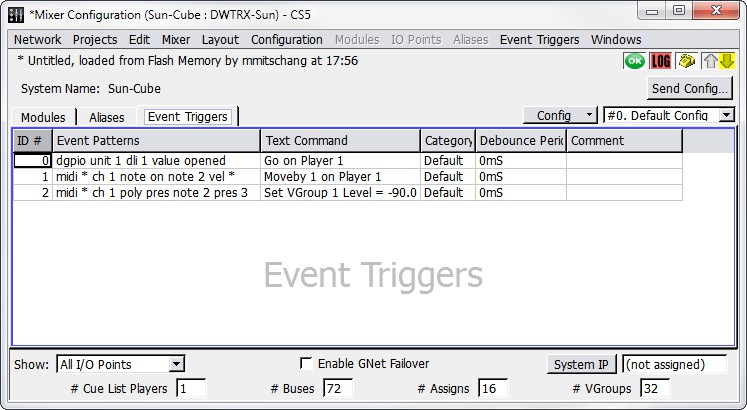
Mixer Configuration Window, Event Triggers Tab
Choose Event Triggers > New Event Trigger to add Event Triggers to the list. The Event Triggers menu also contains commands to duplicate and delete Event Triggers.
The Mixer Configuration window’s Event Triggers tab displays a table containing the following default columns.
Field | Description |
|---|---|
ID# | The Event Trigger number: assigned automatically when the Event Trigger is created, but can be changed. |
Event Patterns | An Event Trigger consists essentially of two parts: the trigger condition and the action to execute when the condition occurs. The trigger condition can be one of several event patterns. Right-click in the event pattern column and select an event pattern template to add an event pattern to a trigger definition. Template text can be edited directly in the table to define the event pattern portion of the Event Trigger. . The event pattern templates are:
|
Event Patterns (cont.) | All Notes Off |
Note Off | |
Note On | |
Polyphonic Key Pressure | |
Control Change | |
Program Change | |
Channel Pressure | |
Pitch Bend | |
Text Command | The second half of an Event Trigger is what action the D-Mitri system executes when the trigger condition occurs. The command to execute can be one of several CueStation text commands. To assign multiple commands to an Event Trigger, separate them with a semicolon (for example: log recalling cue; recall cue 5). Right-click the Text Command field and choose a text command template to add a text command to a trigger definition. You can then edit the template text directly in the table to define the text command portion of the Event Trigger. . The text command templates are:
|
Category | Provides a means by which to categorize Event Triggers. Use this field to enter a text value representing the category to which you want to assign an Event Trigger. Click the Category column heading to sort the list of Event Triggers by category, or right-click the Category column heading to filter the display by Category content. |
Debounce Period | Specifies a debounce period for the selected Event Trigger, in milliseconds. The debounce period defines a time during which the trigger only fires once. For example, entering 500ms in the field would ensure that the trigger doesn’t fire more than twice a second. |
Comment | Provides an area for text comments. |
Configuring a D-Mitri backup module
It is beneficial to designate a live backup module, which you can set to come online should a primary module suddenly become disabled or disconnected. Settings on backup modules are kept in sync with primary modules, ensuring that the backup modules come online seamlessly to assume the tasks of the modules they replace. In D-Mitri systems with multiple DCPs, a single backup DCP can take over for any one of the primary DCPs.
You can use CueStation to designate DCP, DCM-2, DCM-4, and Wild Tracks modules as backup modules. The following table briefly describes how each kind of backup module should be set up.
Module | Backup Configuration |
|---|---|
DCP | A live backup DCP must be given the unit ID DCP-X in the Mixer Configuration window, and must be plugged into the last matrix link port, labeled Backup, on a DCM module. One live backup DCP can stand in for any one of up to 4 primary DCP modules. |
DCM-2 or DCM-4 | A live backup DCM-2 or DCM-4 must be given the unit ID MTRX-X in the Mixer Configuration window. |
Wild Tracks | Both the primary and the live backup Wild Tracks units must be configured with the same unit ID (though this ID can be whatever you want). Associate I/O Points only with the primary Wild Tracks module. |
Disabling D-Mitri modules remotely
D-Mitri modules can be enabled or disabled directly through the System Status window, or by executing a Set Disabled Modules command with a subcue. Disabling marks the module as one that should not be used for passing audio, forcing the system to use its assigned backup modules for audio routing instead.
Status window module enable or disable
Right-click a module’s Status field to raise a context menu with choices to set the module to Enabled or Disabled.
Subcue window Set Disabled Modules command
The External Command subcue Live Backup can be used to enable or disable the module.
Testing a Configuration
Once a configuration has been sent to the CueStation system, it can be tested by generating test signals with CueStation and with signals created by connected external sources.
Testing with internally generated signals
Channel test functionality is built into the multiple windows in CueStation. This functionality allows testing of a configuration and connected loudspeakers. Test signals can be generated at the inputs, outputs, and several other locations in the CueStation signal path.

Channel Test Controls
Channel Test Controls offer the following controls.
Control | Function |
|---|---|
Channel Test Set | Sets the range of channels to be tested. Enter a single channel, a range of channels, or choose Reset to All Channels. Individual channels are separated by commas, channel ranges are indicated with hyphens. For example, typing 1,14,36–41 in the field specifies a test for channels 1, 14, and 36 through 41. |
Merge/Replace | Toggle whether to merge the chosen test audio with other output in the selected channels, or to replace the output with the test audio. |
Channel Test Type | Determines the type of test audio. Options include Voice, Voice and Pink Noise, Pink Noise (8 seconds), Log Sweep, and Pink Pulse. |
Channel Test Level | Determines the level of generated test signals. This setting operates independently of all level and trim controls in the CueStation signal path. |
Start/Stop Test | Begins the test. While the test is running, the Stop Test button ends the test. |
Current Channel | Indicates the channel that is currently being tested. Values that are manually entered in this field act as offsets. |
Transport buttons | Used for manual changes to the channel sequence. Test signal can be skipped to the previous or next channel, looped on the current channel, and paused. |
Preparing for a channel test
Choose Windows > Inputs to open the Inputs window.
Choose Display > Show Channel Test Controls to reveal the signal generator controls at the top of the Inputs window.
Click the Master Input Select button to select all Input channels.
Command-click (Mac) or Ctrl-click (Windows) the Unity button on any Input channel to set all selected channel faders to Unity.
In the bus assigns section of Input 1, select Bus 1. Repeat for all inputs, cascading the Bus selection (Input 2 to Bus 2, and so on).
Choose Windows > Matrix to open the Matrix window.
Choose Matrix > Set Diagonal, Buses, Outputs. A diagonal matrix mix is created with levels set to unity gain.
Choose Windows > Output Masters to open the Output Masters window.
Click the Master Output Select button to select all input channels.
Command-click (Mac) or Ctrl-click (Windows) the –inf button on any Input channel to set all selected channel faders to –inf.
Choose Windows > Grand Master to open the Grand Master window.
Click the Unity buttons for System Level and Trim to set fader levels to Unity.
Running a channel test
Complete the steps detailed in Preparing for a Channel Test.
Enter a value in the Channel Test Set field to set the range of channels to test.
Choose an option from the Channel Test Type menu to set the type of test signal.
Enter a Channel Test Level value to set the test signal level in dB.
Click Start Test to begin the channel test.
Choose Windows > Output Masters to open the Output Masters window.
Slowly increase the output fader levels until the test signal is playing back through connected loudspeakers at the necessary level. To adjust the levels of all Output channels simultaneously, click the Master Output Select button and then hold command (Mac) or Ctrl (Windows) while adjusting any Output channel fader.
Tip
For manual control over the test sequence, use the Cycle button in conjunction with the Skip to Previous Channel and Skip to Next Channel buttons.
Testing with external signals
External test signals can be fed into the CueStation system’s inputs, andthen sent to any or all outputs. The following procedure uses a single input point, Input 1, as an example.
Choose Windows > Inputs to open the Inputs window.
Click the Unity button for Input 1 to set the fader level to Unity.
In the Bus Assigns section of Input 1, select Bus 1.
Choose Windows > Matrix to open the Matrix window.
Choose Matrix > Set Diagonal, Buses, Outputs. A diagonal matrix mix is created. All bus masters and output masters are set to Unity.
Choose Windows > Grand Master to open the Grand Master window.
Click the Unity buttons for System Level and Trim to set fader levels to Unity.
Audio connected to Input 1 is mixed to Output 1. To change the output path, select a different bus from the bus assigns section of Input 1.