MPS-482HP Power Supply Front and Rear Panels
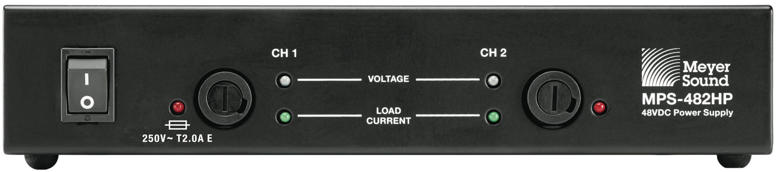
MPS-482HP Power Supply Front Panel
The MPS-482HP Power Supply front panel includes a power switch and LEDs for monitoring each loudspeaker channel.
MPS-482HP Power Supply Front Panel
AC Power
The MPS-482HP Power Supply is powered on and off with the AC Power switch.
Fuse, Voltage, and Load Current LEDs (1–2)
The Fuse, Voltage and Load Current LEDs are useful for verifying if a channel fuse is open/blown, whether each channel output has voltage, and whether the connected loudspeakers are receiving DC power and audio.
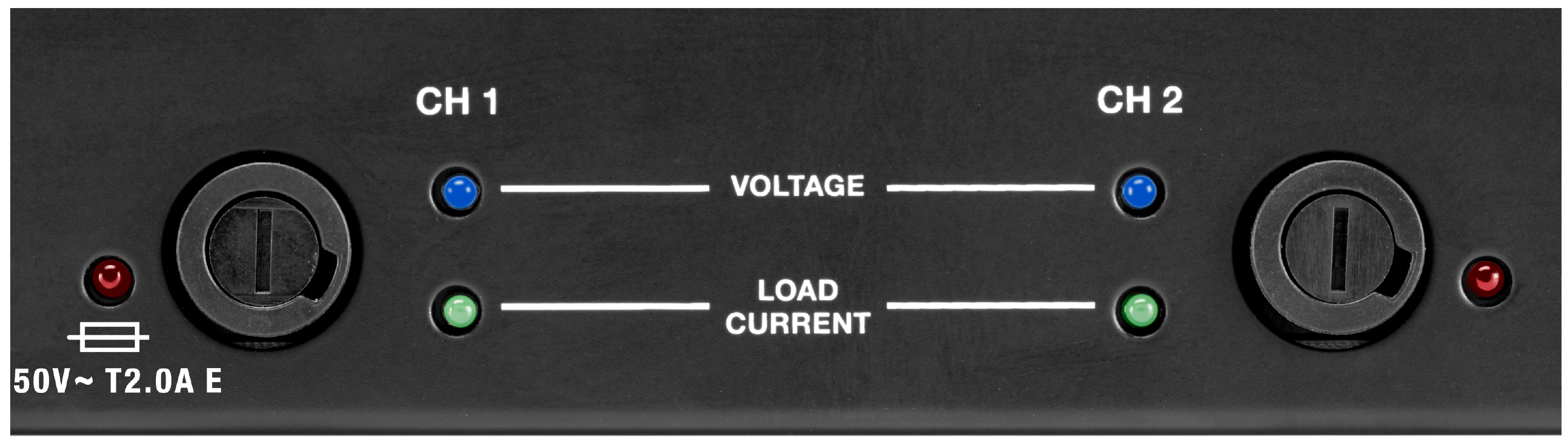
MPS-482HP Power Supply Channel LEDs
Red Fuse LEDs (1-2)
A lit red LED indicates a blown or open fuse on that channel. If the Red LED is lit, power down the MPS-482HP Power Supply and check for shorts on the loudspeaker cabling before replacing the fuse.
Tip
To replace a fuse, use a screwdriver to gently turn the appropriate fuse cover (open: counterclockwise; close: clockwise).
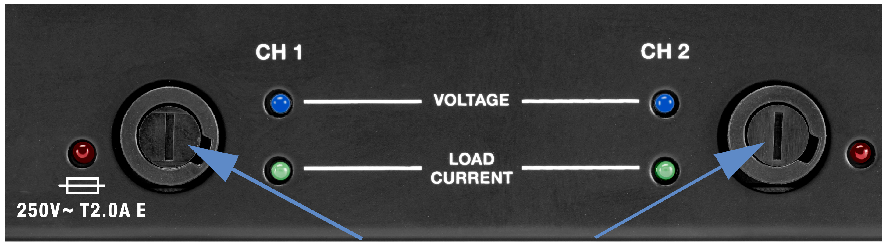
Fuse Access
Blue Voltage LEDs (1–2)
The blue Voltage LEDs indicate whether voltage is present for the channel outputs. These LEDs should be lit when the MPS-482HP Power Supply is powered on. The MPS-482HP Power Supply’s intelligent circuit protection shields connected loudspeakers from surges and shorts. When a blue Voltage LED is unlit and its corresponding green Load Current LED is off, a surge or short has been detected for the channel. If a surge or short is encountered, or the Red LED is lit, power down the MPS-482HP Power Supply, inspect the loudspeaker cabling, and replace the fuse for that channel.
The table below lists the possible states for the Blue Voltage LEDs.
State | Cause | Recommended Action |
|---|---|---|
Unlit (all LEDs) | MPS-482HP Power Supply not powered on or is unplugged | Verify the MPS-482HP Power Supply is powered on and verify its power source. |
Unlit (single LED) | Surge or short encountered for channel | Power down the MPS-482HP Power Supply; inspect the loudspeaker cabling for the channel. |
Caution
When a blue Voltage LED is unlit, power down the MPS-482HP Power Supply,and inspect the loudspeaker cabling for that channel.
Green Load Current LEDs (1–2)
The green Load Current LEDs indicate whether loudspeakers are connected to the channel outputs and receiving power. If a green LED is not lit, check that the channel’s blue Voltage LED is lit and verify the cable connection to the loudspeaker.
The table below lists the possible states for the Load Current LEDs.
State | Cause | Recommended Action |
|---|---|---|
Unlit (all LEDs) | MPS-482HP Power Supply not powered on or no loudspeakers connected | Verify the MPS-482HP Power Supply is powered on and verify its power source; inspect the loudspeaker cabling. |
Unlit (single LED) | No loudspeaker connected | Power down the MPS-482HP Power Supply; inspect the loudspeaker cabling for the channel. |
Glows brighter (single LED) | LED glows brighter as channel’s audio signal level increases | None required. |
Caution
When a blue Voltage LED is unlit and its corresponding green Load Current LED is unlit, indicating a surge or short for the channel, power down the MPS-482HP Power Supply and inspect the loudspeaker cabling for that channel.
MPS-482HP Power Supply Rear Panel
The MPS-482HP Power Supply rear panel includes an AC input connector, two XLR inputs and one 6-pin Phoenix input for receiving two channels of source audio, a Link switch to route audio from input 1 to both outputs, and two Phoenix 5-pin outputs for delivering two channels of balanced audio along with DC power.
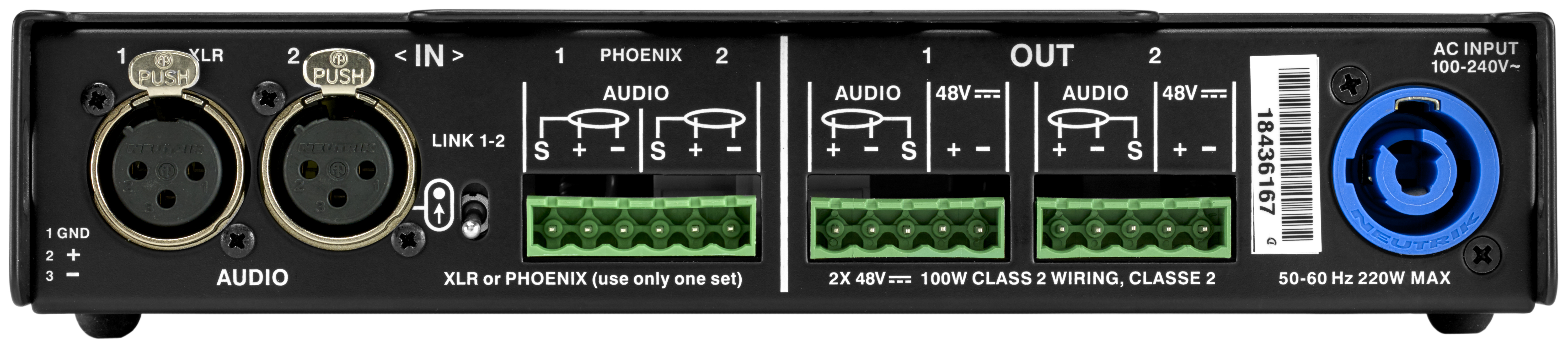
MPS-482HP Power Supply Rear Panel
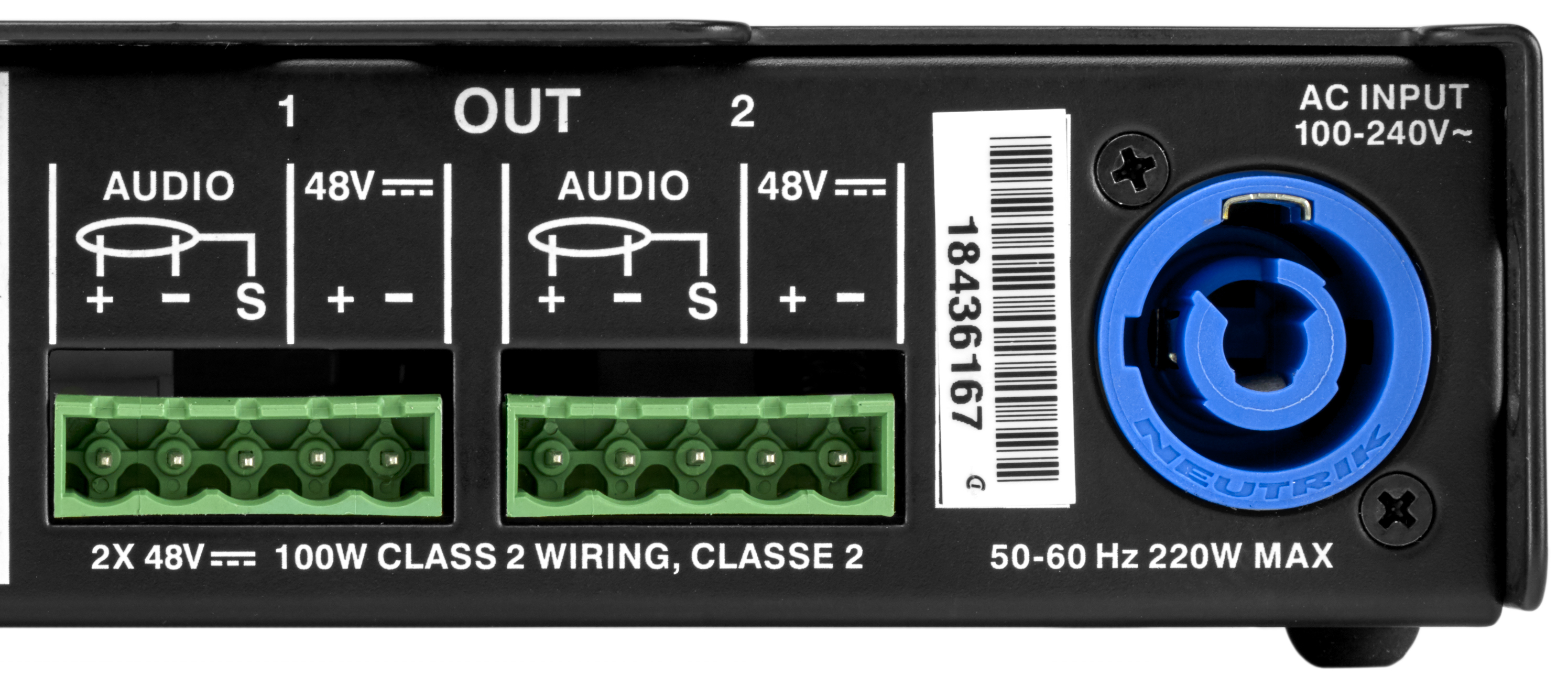
AC Input
The MPS-482HP Power Supply has a powerCON 20 twist-lock AC input connector (line, neutral/line, earth). The connector can accept different power cable types for outlets used throughout the world. Make sure to use the correct power cable for the AC power in the area where it will operate. The MPS-482HP Power Supply operates at an AC voltage range of 100–240 V at 50–60 Hz.
Channel Inputs
The MPS-482HP Power Supply receives two channels of balanced audio via the two channel inputs. The inputs are equipped with two 3-pin XLR female connectors and a 6-pin Phoenix male connector, but only one set may be used at a time. The XLR input connector pinout is: pin 1, ground; pin 2, signal positive; pin 3, signal negative. Make sure to use standard balanced XLR cables with all three pins connected on both ends. The Phoenix input connector supports two channels with the following pinout (from left to right): pin 1, channel 1 ground; pin 2, channel 1 signal positive; pin 3, channel 1 signal negative; pin 4, channel 2 ground; pin 5, channel 2 signal positive; pin 6, channel 2 signal negative.
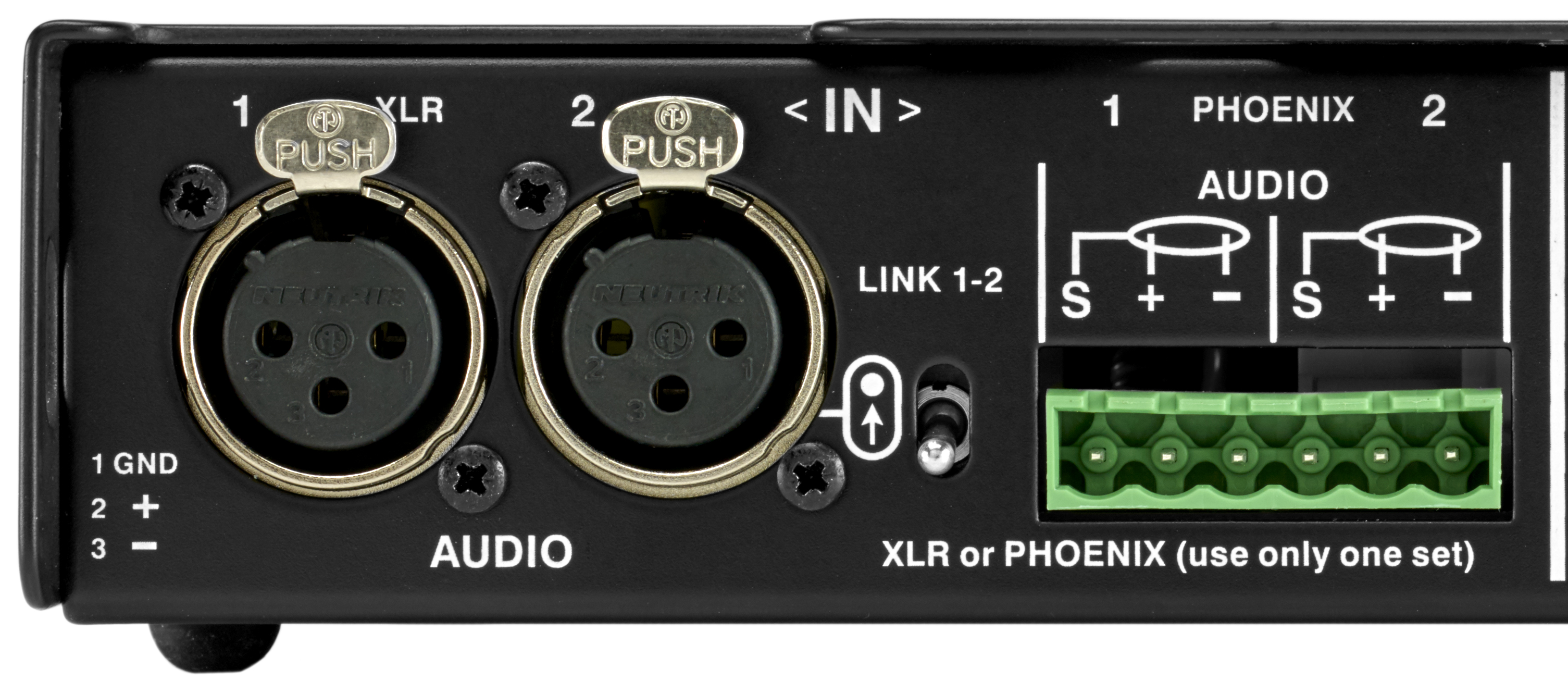
MPS-482HP Power Supply Channel Inputs
Channel inputs default to being routed to their corresponding channel outputs but channel 1 can also be routed to both outputs with the Link switch. This selection affects the input impedance (see Input Impedance for Linked Channel Inputs).
Link Switch
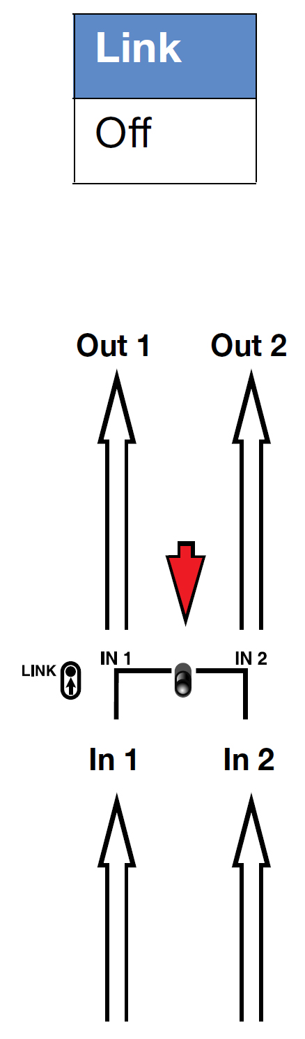
The Link switch determines how the two inputs are routed to the two outputs. When the Link switch is OFF (set to the down position), each input is only routed to its corresponding output (input 1 routed to output 1 and input 2 is routed to output 2).
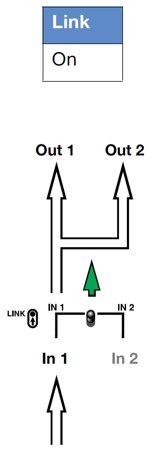
When the Link switch is ON (set to the up position), input 1 is routed to both output 1 and output 2.
Note
Input 2 is inactive when the Link switch is enabled. Connections should not be made to the inactive input.
Link Switch Routing Examples
The following examples illustrate the routing applications for the Link switch.
Routing One Input to Two Outputs
To route input 1 to both channel outputs, set Link switch to ON.
Routing Each Input to its Corresponding Output
To route each input to its corresponding channel output, set Link switch to OFF.
Input Impedance for Linked Channel Inputs
When the Link switch is enabled, channel 1 input’s unbuffered source signal is transmitted in parallel to both channel 1 and 2 outputs. This selection causes the channel input’s impedance (normally 10 kOhms for one loudspeaker) to be reduced for each linked output. For example:
one channel output, 10 kOhm input impedance
two channel outputs, 5 kOhm input impedance
Note
To avoid distortion when linking channel inputs, make sure the source device can drive the total load impedance of the linked loudspeakers. Most source devices are capable of driving loads no smaller than 10 times their output impedance. To drive two loudspeakers linked from a single channel input, the source device should have an output impedance of less than 500 ohms.
Channel Outputs
The MPS-482HP Power Supply’s two channel outputs deliver DC power (48 V DC) and balanced audio to two loudspeakers. The channel outputs are Phoenix 5-pin male connectors.
Caution
Make sure loudspeaker cables are wired correctly. For details about assembling loudspeaker cables, refer to Assembling Loudspeaker Cables.
Note
For information about cable requirements for a particular loudspeaker, refer to its operating instructions. For information about cables and cable accessories available from Meyer Sound, see MPS-482HP Power Supply Cable Accessories.
HMS-15 loudspeakers require power from both channels of the MPS-482HP Power Supply. If audio signal is present on both channels connected to an HMS-15, the signal is summed internally.
Tip
A single composite cable (such as Belden 1502 or equivalent) wired for both DC power and balanced audio can be used to connect loudspeakers to channel outputs.
MPS-482HP Power Supply Channel Outputs
The MPS-482HP Power Supply channel outputs are Phoenix 5-pin male connectors with three pins for balanced audio (positive, negative, and shield) and two pins for DC Power (positive and negative). The pins are clearly labeled on the MPS-482HP Power Supply rear panel.
MPS-482HP Power Supply Channel Outputs
MPS-482HP Power Supply Current Draw
The current draw for the MPS-482HP Power Supply and its connected loudspeakers is dynamic and fluctuates as operating levels change. Because different cables and circuit breakers heat up at varying rates, it is important to understand the following types of current ratings and how they affect circuit breaker and cable specifications.
Idle Current: the maximum rms current during idle periods.
Maximum Long-Term Continuous Current: the maximum rms current during a period of at least 10 seconds. The maximum long-term continuous current is used to calculate temperature increases for cables to ensure that cable gauge and size conform to electrical code standards. This current rating is also used as a rating for slow-reacting thermal breakers, which are recommended for loudspeaker power distribution.
Burst Current: the maximum rms current during a period of around 1 second. The burst current is used as a rating for magnetic breakers. It is also used for calculating the peak voltage drop in long AC cable runs according to the following formula:
V pk (drop) = I pk x R (cable total)
Maximum Instantaneous Peak Current: a rating for fast-reacting magnetic breakers.
Inrush Current: the spike of initial current encountered when powering on.
The minimum electrical service amperage required by an MPS-482HP Power Supply is the sum of the maximum long-term continuous current for all loudspeakers connected to the MPS-482HP Power Supply. An additional 30 percent above the minimum amperage is recommended to prevent peak voltage drops at the service entry.
Note
For best performance, the AC cable voltage drop should not exceed 10 V, or 10 percent at 115 V and 5 percent at 230 V. Make sure that even with AC voltage drops that the AC voltage always remains within the operating window.
Electrical Safety Guidelines
Pay close attention to these important electrical and safety guidelines.
This Meyer Sound product requires a grounded outlet. Always use a grounded outlet and plug.
Do not use a ground-lifting adapter or cut the AC cable ground pin
The AC power connector must not be engaged or disengaged when under load or live.
Disconnect the mains plug before disconnecting the powerCON plug from the unit.
Keep all liquids away from the unit to avoid hazards from electrical shock.
Do not operate the unit if the power cable is frayed or broken.