SpaceMap
SpaceMap multichannel surround panning enables the placement and movement of sound through space using a graphical interface. This chapter contains definitions of the elements that make up SpaceMap, instructions for integrating SpaceMap automation, and design guidelines on how to set up SpaceMap for various applications.
Traditional pan controls for stereo sound are one-dimensional. They shift sound along a line between two points: left and right. A SpaceMap, on the other hand, uses a two-dimensional layout (shown below), and can even be used for three-dimensional work. It can position sound anywhere on a plane, or anywhere in space.
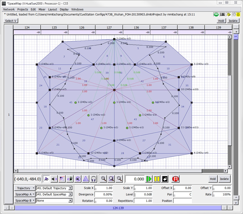 |
SpaceMap Window
Elements of SpaceMap
A SpaceMap design is constructed from two basic elements: nodes and Trisets. Nodes com- monly represent the positions of loudspeakers or groups of loudspeakers, and can be of sev- eral types. Trisets link three nodes together, providing the means to distribute signal proportionally among them. A Trajectory is the path along which the spatial pan control trav- els.
Nodes
Nodes are the points that audio is panned to within a map. They can represent physical loud- speakers (Speaker nodes) or simulate an output location (Virtual nodes). Nodes can also derive their audio from other nodes (Derived nodes), or discard their audio completely (Silent nodes). These types are defined in “Types of Nodes” on page 135.
Trisets
Trisets are triangular panning surfaces defined by three nodes. They ensure a smooth pan without signal drop, like a two-dimensional panning law used by a conventional pan pot. Just as two points are the minimum required to define a line, three points are the minimum required to define a plane.
CAUTION: Trisets cannot overlap one another: signal distribution would be unpredictable within the overlapped areas. An overlapping Triset turns red as a
warning.
 NOTE: In circumstances where a single loudspeaker is included in a SpaceMap Triset twice—once as a Triset node, and again as a Derived Node linked to one of
the Triset nodes—CueStation now interprets the two inclusions to make the output level a sum of the two roles’ output levels.
The size of the Triset is not critical because the power-preserving panning law is proportional rather than absolute. It is based on the relative distance between the spatial pan control and each of the three surrounding nodes, rather than the actual physical distance within the grid.
Trajectories
The path along which a sound moves is called a Trajectory. A trajectory can be recorded, edited, and reshaped, then mapped to an input bus and recalled as part of a SpaceMap Tra- jectory subcue.
Trajectories can create the illusion of a moving sound, fade sounds in and out, or control a variety of other effects depending on the design of the map. The relative position of the SpaceMap bus within a Triset determines the proportion of signal sent to each of the nodes in the Triset. The actual signal levels can be seen in the Matrix window, along the row of the input bus assigned to the control.
Each trajectory is an entirely independent entity, with no absolute relationship to any one map. One map can have several different trajectories, or one trajectory for several different maps. Several trajectories can be active at once (one per bus), and there can be an arbitrary number of trajectories (and maps) in a project file.
Additionally, a trajectory can be played back with real-time modifications, such as the number of repetitions, rate, orientation, scaling, and offset in both X and Y dimensions. Several copies of the same trajectory could be assigned to different buses and performed simultaneously with different modifiers on each.
Types of nodes
There are several types of SpaceMap nodes, each serving a different function.
Trajectory Nodes
Trajectories are comprised of Trajectory nodes. Where Trisets represent loudspeaker locations and establish points from which to derive relative panning, Trajectory nodes represent the cur- rent position of a signal in each plane.
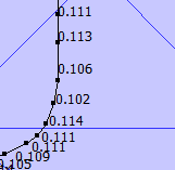 |
Trajectory Nodes
Each TrajectoryNode contains information on both temporal and positional axes, and can have a level setting independent of the Trajectory’s level. In addition, nodes can be named and can recall text commands.
Speaker Nodes
Speaker nodes represent the physical outputs in the D-Mitri system.
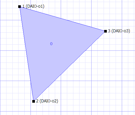 |
Triset Containing Speaker Nodes
Each speaker node is assigned to a single output. Outputs can be connected to loudspeak- ers, effects processors, or any other devices. Multiple nodes can be assigned to the same output. When a Triset contains three Speaker nodes, the audio is distributed amongst the nodes as determined by the location of the bus or trajectory within the Triset, and the relative distance between the nodes. For more information on how to create these nodes, see “Add- ing Nodes” on page 146 and “Creating Trisets” on page 147.
Virtual Nodes
A Virtual Node simulates a physical output in space by distributing its signal to the Speaker nodes to which it is linked.
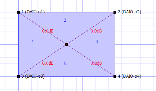 |
Virtual Node Simulating the Center of a Quadraphonic SpaceMap
By default the signal is divided equally among all the linked Speaker nodes, but proportional Link Gains can be defined that change the balance of the distribution. For more information on how to create these nodes, see “Adding Nodes” on page 146.
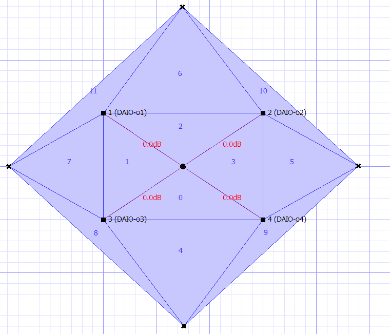
In this example, the Virtual Node is linked to the four Speaker nodes so that any signal that is assigned to it is equally distributed among the surrounding loudspeakers. Thus a trajectory traveling around the perimeter of the map pans linearly from one loudspeaker to the next, but a trajectory that moves toward the Virtual Node at the center of the map causes the signal to spread out to all four loudspeakers gradually. This proportional distribution method creates a convincing phantom image throughout the panning area.
Silent Nodes
A Silent Node takes part in a Triset in place of a Speaker Node but it is not associated with an output.
 |
Silent Nodes Providing Fade Thresholds to a Quadraphonic SpaceMap
A signal panned toward a Silent Node simply disappears, providing an easy way to create fade-in and fade-out effects. This feature also solves the signal dropout problem that exists when a trajectory strays outside the panning area defined by a Triset of Speaker nodes. Since the area outside the map is currently undefined, the signal abruptly drops out. By surrounding the existing map with Silent nodes, we can create a perimeter of fadeout Trisets and guard against unintended loss of signal.
For more information on how to create these nodes, see “Adding Nodes” on page 146.
To complete our model, place four Silent nodes, one outside each side. Create Trisets, each with two Speaker and one Silent Node, or two Silent and one Speaker Node. The Speaker nodes entirely enclosed within Trisets, sound panning is now gap-free.
Derived Nodes
The Derived Node provides a way to send a signal to a secondary output whenever that signal is also being sent to a set of Speaker nodes.
 |
Derived Node Providing a Mono Sum Output in a Quadraphonic SpaceMap
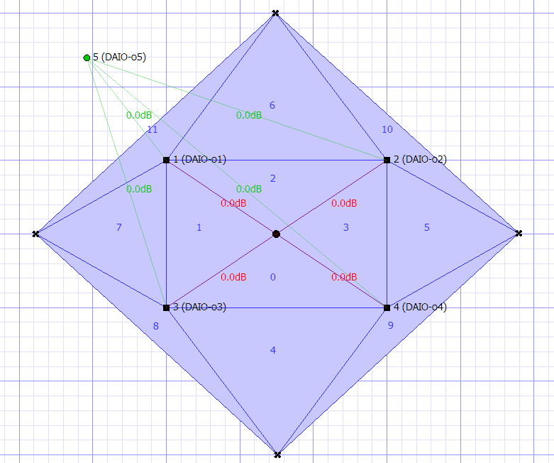
Derived nodes link to one or more Speaker nodes, and receive a sum of the signals from its linked Speaker nodes. Each link between Speaker nodes and Derived nodes can be adjusted in decibels, from -89 dB to +10 dB.
Derived nodes are commonly used for subwoofer sends, fill mixes, balconies, and other cases where a secondary mix-down of a multichannel mix is required. For example, a Derived Node feeding a single subwoofer would be linked to all the main channels, so that the subwoofer receives a constant feed even if the source signal is being panned. For more information on how to create these nodes, see “Adding Nodes” on page 146.
Link Gains
By default, Virtual and Derived nodes distribute and receive, respectively, an equal proportion of the signal of their linked nodes. Link Gains allow the alteration of these proportions.
When selecting a Virtual or Derived node and its one or more linked nodes, the amount of linked gain can be changed using the Set Link Gains command (see “Setting Link Gains” on page 149).
Link Gains for Virtual and Derived nodes are expressed in decibels, with a maximum value of
+22.1 dB. Any number that is entered, down to -90 dB, is considered negative unless it is pre- ceded by a + sign.
SpaceMap Controls
In the SpaceMap window, each bus has its own SpaceMap grid view, trajectory parameters, and tools for editing both maps and trajectories.
At the top of each bus view is the matrix row, which displays exactly how much signal is going to each output.
SpaceMap Grid
Most of the SpaceMap window is devoted to a drawing area. This is where nodes are placed and linked, Trisets created, and trajectories are drawn.
 TIP: The display scaling can be decreased with Command+[ (Mac) or Ctrl+[ (Win- dows), and increased with Command+] (Mac) or Ctrl+] (Windows). The display
can be re-centered using the scroll bars.
Grid settings
There are two different grid options: Cartesian and Polar. The displayed grid type and size can be changed in the Display menu.
For cleaner-looking maps and trajectories, choose Display > Snap to Cartesian Grid or Display
> Snap to Polar Grid.
Editing tools
Directly below the SpaceMap grid view is a row of buttons for selecting different editing tools. As they appear from left to right, the buttons offer the following functions.
Button | Function |
|---|---|
Select | Select objects, Trisets, and Trajectory nodes. (Note that this is different from the Select button in the upper left corner.) |
Add Speaker Nodes | Click the grid to add Speaker nodes. |
Add Virtual Nodes | Click the grid to add Virtual nodes. |
Add Derived Nodes | Click the grid to add Derived nodes. |
Add Silent Nodes | Click the grid to add Silent nodes. |
Add Trisets | As the mouse is moved around the grid, preview lines indicate where a Triset would be placed. Click to create the Triset. Each set is numbered in order of creation. |
Test | Drag to test different locations on the grid with the active bus. This is a good way to experiment with a trajectory path. |
Trajectory Playback Controls
Below the SpaceMap grid area, there is a set of trajectory playback controls. The text box dis- playing a time in milliseconds shows the position of the bus along the trajectory, relative to time. The transport controls include the following.
Control | Function |
|---|---|
Play | Starts the bus moving along the selected trajectory's path. When playing back a trajectory, the spacebar can be used to play and pause. |
Pause | Pauses the movement of the bus. |
Stop | Stops the movement of the bus, and repositions it at the start of the trajectory. The Enter key can be used to stop a playing trajectory. |
Record | Enters record mode, for recording a trajectory. The process of recording a new trajectory is fully described in “Creating Trajectories” on page 149. |
Hold | Holds playback of the Trajectory, similar to the way the Hold button holds playback of a Wild Tracks deck in the Wild Tracks window. |
Isolate | Isolates playback of the Trajectory, similar to the way the Isolate button isolates playback of a Wild Tracks deck in the Wild Tracks window. |
Transport controls can be shown and hidden through the Display menu.
Bus Playback settings
This section of the window contains the SpaceMap automaton settings for each bus.
Setting | Definition |
|---|---|
Trajectory | Select a trajectory from the drop-down menu, or access Trajectory editing functions. |
SpaceMap A | Select a map for the trajectory to travel through, or access SpaceMap editing functions. |
SpaceMap B | Optionally select a second map, in order to pan the trajectory between two different maps. |
The following parameters are visible when Display Show Playback Details is enabled. These parameters control how a bus moves along the selected trajectory, but do not affect the actual trajectory. They are not saved with each SpaceMap or Trajectory.
Parameter | Definition |
|---|---|
Scale X | Multiplies the value of the X coordinate (horizontal). |
Scale Y | Multiplies the value of the Y coordinate (vertical). |
Offset X | Adds an offset value to the X coordinate (horizontal). |
Offset Y | Adds an offset value to the Y coordinate (vertical). |
Divergence | Controls the amount of bleed to all other SpaceMap nodes. |
Level | Controls the volume of audio signal routed to SpaceMap nodes, from +10.0 dB to -inf (silence). |
Pan | Sets the pan value between two maps. This control has no effect when SpaceMap B is set to None. |
Rate | Controls the relative speed at which the bus moves along the trajectory. |
Rotation | Rotates the trajectory path around the origin (0,0) by a relative amount. |
Repetitions | Controls how many times the bus traverses the trajectory before stopping. |
Position | Sets the starting position of the bus along the trajectory path. |
Trajectory Editor
Choose Display > Show Trajectory Editor to view the Trajectory Editor.
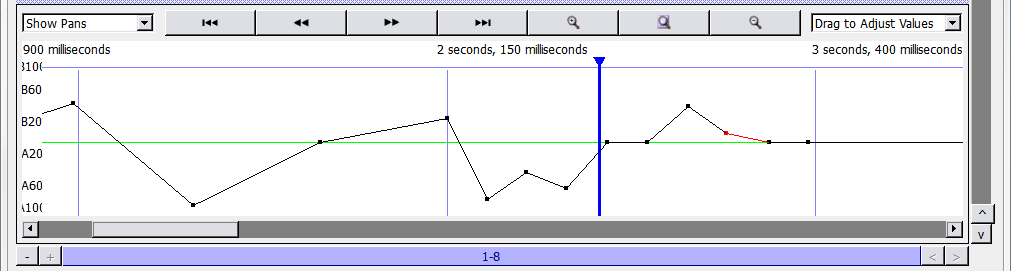 |
Trajectory Editor
The trajectory editor shows a timeline view of the currently selected trajectory. A drop-down menu in the upper left changes the Trajectory Editor display between Level, Pan, or Diver- gence of each TrajectoryNode. Across the top are buttons for scroll to start, scroll left, scroll right, scroll to end, zoom in, zoom to fit, and zoom out.
These controls affect the actual trajectory, and the parameters affect all buses that uses the trajectory.
SpaceMap Grid Settings
These settings change the appearance and behavior of the background grid through the Dis- play menu.
Setting | Effect |
|---|---|
Show Matrix Rows | Display the matrix rows at the top of the grid. |
Show SpaceMaps | Display the grid. |
Show Transport Buttons | Display the trajectory playback controls. |
Show Trajectory Editor | Display the trajectory editor at the bottom of the screen. |
Show Playback Settings | Display the bus playback settings controls. |
Show Playback Details | Display the playback details value boxes to the right of the trajectory but- tons. |
Setting | Effect |
|---|---|
Show Mouse Coordinates | Display a value box to the left of the editing tools, which shows the mouse's current position as map coordinates. |
Show All Bus Positions | Display all bus positions at once on the grid. |
Show Bus Names | Display the name of the visible bus points. |
Show Names | Display the names of all Speaker nodes. |
Show Links | Display all links. |
Show Nodes | Display all Speaker nodes. |
Show Trajectories | Display all trajectories. |
Show Node Durations | Display time between Trajectory nodes. |
Show Trisets | Display the Trisets. |
Show Images | Display any images added to the SpaceMap. |
Opaque Trisets | Display Trisets as filled with color, preventing the grid from being visible through them. |
Show Cartesian Grid | Display a Cartesian (square) grid. |
Snap to Cartesian Grid | Snap all SpaceMap objects to Cartesian grid points. |
Set Cartesian Grid Spacing | Set the spacing of Cartesian grid lines. |
Show Polar Grid | Show a polar (circular) grid. |
Snap to Polar Grid | Snap all SpaceMap objects to polar grid points. |
Set Polar Grid Spacing | Set the spacing of polar grid lines. |
Show Page Group Controls | Shows or hides the Page Group controls on the bottom of the screen. See “Page Group Controls” on page 199. |
Inserting an image
Image files can be inserted onto the grid as a reference to assist with the placement of nodes. This function can be used to place an architectural drawing or other reference image directly onto the SpaceMap grid. Supported file types are BMP, GIF, ICO, JPEG, JPG, MNG, PBM, PGM, PNG, PPM, TGA, TIF, TIFF, XBM, and XPM.
To insert an image into a SpaceMap:
Click either the SpaceMap A or SpaceMap B drop-down menu.
Choose Insert Image.
Navigate to the file location of the image and select it.
Click Open.
The image is scaled to match the SpaceMap size, and placed on the grid. To move the image, drag with the Select Objects tool.
Image control
Images can be resized by Shift+dragging. Image placement and properties can be altered after images have been inserted into a space map. To change image properties, right-click the image and select an option from the resulting menu.
Control | Function |
|---|---|
Lock Image | Merges the image with the background, removing it from the list of selectable objects. |
Unlock Image | Restores the image as a selectable object. |
Set Display Prior- ity | A numerical value which instructs the image as to which objects in the SpaceMap to visually occlude. |
Duplicate Image | Inserts an identical copy of the selected image onto the SpaceMap. |
Delete Image | Removes the selected image from the SpaceMap. |
Creating a SpaceMap
This section describes the process of creating and editing a new map. To create a blank SpaceMap:
Click the SpaceMap A button.
Select New SpaceMap,
Enter a name.
Adding Nodes
The first step in building the SpaceMap is to add Speaker nodes, Virtual nodes, Derived nodes, and/or Silent nodes.
Click Add Speaker Node.
Click anywhere in the map grid to add Speaker nodes.
Click Add Virtual Node, Add Derived Node, or Add Silent Node, then click the grid to add other types of nodes.
Speaker nodes and Derived nodes are numbered with the corresponding output channel.
Modifying Nodes
Click the Select tool.
Select the nodes to be modified. Click a single node to select it. Several nodes can be selected by holding down the Shift key while clicking nodes, or by dragging a selection box around them.
Other operations that can be performed with the Select tool include:
Drag the node(s) to a new position.
Change the node(s) types. Right-click the selected node(s), choose Set Nodes Types, and select Speaker, Virtual, Derived, or Silent.
Delete the node(s). Use the Delete key, or right-click one of the selected node(s) and choose Delete Nodes.
Link or Unlink the connection between virtual or Derived nodes and their associated Speaker nodes. Right-click the selected node(s) and choose Link Virtual/Derived Nodes or Unlink Virtual/Derived Nodes.
Change the output channel for a single node. Select a node and type the channel number of the output. Or, right-click a node, select Set Output, and choose an output channel number.
Give a single node a name. Right-click a node and choose Rename. The name is displayed beside the node.
Right-click a node (or set of nodes) to edit it with the following parameters.
Parameter | Definition |
|---|---|
Set Node Type | Select from Speaker, Virtual, Derived, or Silent. |
Set Output | Select the output number from the list, or type a number and press Enter. |
Set Aux | Select the aux number from the list, or type a number and press Enter. |
Set Node Trim | Enter a trim level for the node. |
Rename Node | Enter a new name for the node (this does not change the number in front of the name). |
Add Triset | When three nodes are selected, choose Add Triset to create a Triset connect- ing them. |
Delete Triset | Removes the Triset. |
Link Virtual/Derived Nodes | Creates links between the Virtual or Derived Node and the currently selected Speaker nodes. |
Unlink Virtual/Derived Nodes | Removes any links to the currently selected nodes. |
Set Derived Link Gains | Type in a number from +22.1 dB to -99.8 dB. |
Delete Node | Deletes the currently selected nodes. |
Creating Trisets
Add Trisets to create zones for the SpaceMap buses to move through. buses that are outside of a Triset do not produce any output signal.
Click Add Triset.
Move the pointer to the middle of any three nodes. A light green line shows the proposed Triset.
Click to create that Triset.
Alternatively, three nodes can be selected and combined. Right-click and choose Add Triset. To rename a Triset, right-click the Triset and choose Rename Triset.
CAUTION: Trisets can not overlap one another: signal distribution would be unpredictable within the overlapped areas.
Deleting Trisets
Click Add Trisets.
Click a Triset to remove it.
Alternatively, using the Select tool, right-click a Triset and choose Delete Triset. If a node that is part of a Triset is deleted, the Triset itself is deleted as well.
Testing Trisets
Set mixer control points to route audio signal to a bus.
Click the Test button.
Drag the bus through the map.
If the Speaker nodes are sending to functioning loudspeakers, the sound pans through the Trisets.
Output signal distribution changes as the bus is moved; the bus is represented as a small hol- low circle. Its label corresponds to the bus label. Level changes can be observed in the Matrix display, and at the top of the SpaceMap window.
Linking Nodes
Derived nodes and Virtual nodes must be linked to Speaker nodes in order to function.
Select the virtual or Derived Node, plus other nodes to link it to. For Virtual nodes, these are nodes that receive signal from the Virtual Node. For Derived nodes, these are nodes that send signal to the Derived Node.
Hold down the Shift key and click each node to select them.
Right-click the selected nodes and choose Link Virtual/Derived nodes. Each link is labeled with its Link Gain, a value representing the proportion of signal it sends.
Unlinking Nodes
To remove all the links for a virtual, derived, or Speaker Node, right-click the node and choose Unlink Virtual/Derived nodes.
Setting Link Gains
Link Gain behaves like a trim control, adjusting the level of the original signal that reaches Vir- tual or Derived nodes.
To change Link Gain:
Right-click a Link Gain value and choose Set Link Gain.
Enter a new value.
Click OK.
Creating Trajectories
Once a Triset layout has been created, SpaceMap Trajectories can be created and used in cues.
Creating a new Trajectory
To create a SpaceMap Trajectory:
Click the Trajectory button, and select New Trajectory.
Enter a name for the trajectory.
Click Record. The Record button blinks red.
Draw the trajectory on the grid by clicking its start position, then clicking at several discrete locations along the desired trajectory path. Paths can also be drawn by clicking and dragging.
CueStation automatically connects the dots. The time interval between dots initially corresponds to the time between clicks (see “Modifying a Trajectory” on page 150).
To stop recording, right-click in the SpaceMap grid, or move the mouse outside the SpaceMap pane.
Trajectories can be re-recorded by clicking Record again and drawing a new path. This clears the trajectory that was previously recorded.
Tip
Shift-click the Record button to pick up drawing a trajectory where it was left off. The button blinks yellow instead of red to indicate that the trajectory does not clear when recording starts.
Auto-Cue
To record a trajectory in time with Wild Tracks playback, or other types of automation, use the Auto Cue function:
Click the Record button. An Auto Cue checkbox and a Cue text box become visible to the right of the Record button.
Click the Auto Cue checkbox to enable Auto Cue.
Type a Cue ID in the Cue text box. This cue is recalled when the first trajectory point is reached.
Click the map to add a trajectory point. The cue is recalled. Continue placing trajectory points as needed.
To stop the trajectory recording, move the mouse outside the SpaceMap grid.
Tip
Cues can be set to recall along existing trajectories by right-clicking a TrajectoryNode and assigning a text command, e.g. Recall Cue 123.
Modifying a Trajectory
To edit a SpaceMap trajectory:
Select the trajectory from the drop-down menu beside the Trajectory button.
Click the Select tool.
Select points on the trajectory.
Multiple Trajectory nodes can be selected using the Shift key or by dragging a selection box around them. To select and edit multiple noncontiguous Trajectory nodes, hold Shift+Option (Mac) or Shift+Alt (Windows).
Any of the following operations can be performed on Trajectory nodes:
Drag Trajectory nodes to new positions.
To delete a TrajectoryNode, right-click it and choose Delete TrajectoryNode.
To insert Trajectory nodes, right-click a line segment and choose Insert TrajectoryNode.
To adjust duration, right-click a selected TrajectoryNode or line segment and choose Mod- ify Duration. If multiple Trajectory nodes have been selected, the change in duration is dis- tributed proportionally.
Trajectory nodes can recall commands. Right-click a TrajectoryNode and choose Set Text Command. This function can be used to recall cues and subcues once the trajectory passes over a chosen node.
To adjust the offset of an individual segment, right-click the line segment and choose Mod- ify Offset. While the offset can be changed for multiple selected segments, the result also changes the durations of the segments. An alternative to modifying offset for multiple seg- ments is changing the overall duration.
To name the TrajectoryNode, right-click the point and choose Rename TrajectoryNode.
Testing a Trajectory
SpaceMap trajectories can be tested by playing them:
Select the trajectory from the drop-down menu next to the Trajectory button.
Click Play.
To stop playback, click Stop.
 TIP: Observing the Matrix while the bus is moving (by dragging the test control or by playing a trajectory) helps identify awkward transition zones. To ensure seam-
less panning, check that the Trisets have no gaps, and consider using Silent nodes to create a smooth fade-out zone when moving to areas beyond the loudspeaker output sets. A trajectory that crosses any part of the SpaceMap window that is not inside a Triset results in a complete dropout of the signal. It is a useful practice surrounding the main part of the map with a safety zone of Trisets that includes one or two Silent nodes. This results in the sound fading as the bus moves toward the Silent nodes.
Automatic Trajectory Generation
CueStation can auto-draw a trajectory based on a parametric equation. To access this function:
Open the Commands window and add a SpaceMap type entry.
Change the Command to AutoDraw Trajectory.
Enter the values and functions to generate the X and Y coordinates, duration, pan, divergence, and level for each point. The default values create a circle.
Click Recall Selected to have the trajectory drawn automatically. This External Command can also be used in a subcue.
Creating SpaceMap Trajectory subcues
Once a trajectory has been created, trajectory playback can be added to a cue.
Channel Select the bus to assign it to the trajectory.
For that bus, select a trajectory, along with a SpaceMap A (and optionally a SpaceMap B). The SpaceMap grid reflects what you are about to capture.
Open the Capture window using F4, and type a name for the new cue. Or, open the Cap- ture window using F2, and select an already existing cue to add trajectory automation.
Under the bus/matrix category, add a check next to SpaceMap Trajectory, to include that subcue type in the new cue.
Click the Capture button in the bottom right to create the new cue. When the cue is recalled, the selected bus starts moving along the trajectory.
Tip
The current playback position along the SpaceMap trajectory is captured with the cue and saved as the Trajectory PositionPercent control point. A Trajectory PositionPercent of 0.00% sets the cue to start playback at the beginning of the trajectory.