QuickFly Rigging
The ULTRA-X40 and ULTRA-X42 loudspeakers are compatible with Meyer Sound’s QuickFly system, a comprehensive collection of custom-designed rigging, flying, and mounting options. Comprised of rugged, reliable, and easy-to-configure components, QuickFly lets you deploy ULTRA-X40 and ULTRA-X42 loudspeakers as either individual loudspeakers or as arrays at precise angles to take full advantage of their directional components.
Important Safety Considerations
When installing Meyer Sound loudspeakers and subwoofers, the following precautions should always be observed:
All Meyer Sound products must be used in accordance with local, state, federal, and industry regulations. It is the owner’s and user’s responsibility to evaluate the reliability of any rigging method for their application. Rigging should only be carried out by experienced professionals.
Use mounting and rigging hardware that has been rated to meet or exceed the weight being hung.
Make sure to attach mounting hardware to the building’s structural components (roof truss), and not just to the wall surface.
Make sure bolts and eyebolts are tightened securely. Meyer Sound recommends using Loctite® on all threaded fasteners.
Inspect mounting and rigging hardware regularly. Immediately replace any worn or damaged components.
Rigging Points
The top and bottom faces for the ULTRA-X40/42 cabinet include high-strength, corrosion-resistant stainless steel points that provide M8 x 1.25 threaded holes for easy connection to QuickFly rigging and third-party mounting options.
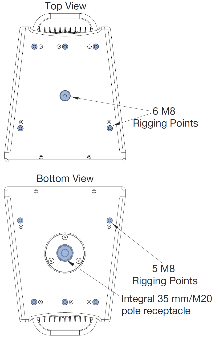
ULTRA-X40/42 Rigging Points
ULTRA-X40/42 Rigging Option Accessories
Meyer Sound offers many rigging options, as listed in the table below, that facilitate a wide variety of configurations.
Model | Features |
|---|---|
MPK-POLE-35MM-M20 Adjustable Pole Mount Kit (PN 40.010.973.01) | Adjustable length 927–1524 mm (36.5–60 in) pole with assisted lift. Lower shaft fits 35 mm cups or use the removable M20 threaded lug for added stability. Upper shaft includes a PAS-M20 Adapter Sleeve to fit loudspeakers with 35 mm and M20 internal pole mounts onto a 35 mm speaker stand. (Can also buy the PAS-M20 Adapter Sleeve separately). Additional 35 mm to 38 mm (1.5 in) adapter included. |
PAS-M20-35MM Adapter Sleeve (PN.40.010.974.01) | Adapts a 35 mm pole to a 35 mm M20 threaded connection to provide additional stability when using 35 mm M20 pole cups. |
MYA-X40 Mounting Yoke Kit (PN 40.287.039.01) | The MYA-X40 Yoke suspends a single ULTRA-X40/42 loudspeaker and supports a wide range of horizontal and vertical adjustments. The yoke attaches to the top of the loudspeaker using three rig nuts. The kit includes three M8 bolts and three M8 knobs. The yoke may also be mounted on a 35 mm pole using the optional MSA-STAND Adapter Cup 35MM accessory to facilitate easy panning and tilting. |
MSA-STAND Adapter Cup 35MM (PN 40.086.013.01) | This compact cup-type adapter can be used to mount the MYA-X40 Mounting Yoke on a pole to allow for easy panning and tilting of the ULTRA-X40/42. |
MUB-X40 U-Bracket Kit (PN 40.287.055.01) | The MUB-X40 U-Bracket allows a single ULTRA-X40/42 loudspeaker to be mounted to a wall (in either vertical or horizontal orientations), to the ceiling or onto the floor. The kit includes two M8 bolts, two M8 knobs, and a 35 mm diameter, Thread Reducer M20 to M8 (35 MM) to convert the cabinet's built-in pole mount internal threads to M8 size. The MUB-X40 U-Bracket can also mount an ULTRA-X40/42 to a pole in the horizontal orientation using the 35MM Pole Stand Adapter. |
35MM Pole Stand Adapter (PN 40.010.971.01) | This large base stand adapter can be used to mount the MTB-X40 Top Bracket or the MUB-X40 U-bracket onto a pole. |
MTC-X40 Top Channel Kit (PN 40.287.130.01) | The MTC-X40 Top Channel kit includes a pinnable link in a channel that mounts directly to the top of the ULTRA-X40/42 rig nuts or into an MCP50-X40 or MCP70-X40 plate and supports pick-up of up to three ULTRA-X40/42 loudspeakers from a single point using the two included lock pins and 3/ 8 in shackle. Using the MTC-X40 Top Channel at the bottom of the ULTRA-X40/42 to pick up multi- ple loudspeakers requires the use of a Thread Reducer M20 to M8 (35MM), which is not included. |
MCP50-X40 Cluster Plate Kit (PN 40.287.100.01) | The MCP50-X40 50 Degree Cluster Plate kit includes two cluster plates to facilitate installation of ULTRA-X40/42 loudspeakers in both horizontal and vertical clusters at angles between 10 and 50 degrees in 5 degree increments. The kit includes eight M8 bolts and eight M8 knobs. The MTC-X40 Top Channel accessory (sold separately) can be attached to the MCP50-X40 as a top pick up point. |
MCP70-X40 Cluster Plate Kit (PN 40.287.400.01) | The MCP70-X40 70 Degree Cluster Plate kit includes two cluster plates to facilitate installation of ULTRA-X40/42 loudspeakers in both horizontal and vertical clusters at angles between 40 and 70 degrees in 5 degree increments. The kit includes eight M8 bolts and eight M8 knobs. The MTC-X40 Top Channel accessory (sold separately) can be attached to the MCP70-X40 as a top pick up point. |
MTB-X40 Top Bracket Kit (PN 40.287.150.01) | The MTB-X40 Top Bracket kit includes a heavy-duty, U-bracket style accessory that facilitates mounting of ULTRA-X40/42 loudspeakers from the ceiling or a truss using the cluster plates. The design supports 5–25 degrees of downtilt and 5 degrees of uptilt. In addition, the MTB-X40 Top Bracket enables mounting of a single ULTRA-X40/42 onto the floor for front-fills. The kit includes four M8 bolts and four M8 knobs. The MTB-X40 Top Bracket can also mount an ULTRA-X40/42 to a pole in the horizontal orientation using the 35MM Pole Stand Adapter. |
Thread Reducer M20 to M8 (35MM) (PN 40.010.540.01) | The Thread Reducer kit includes a 35 mm diameter, M20 to M8 thread size adapter to convert the cabinet's built-in pole mount internal threads to M8 size. It is necessary for installing the MUB-X40 U-Bracket (one included in MUB-X40 U-Bracket kit) and when installing the MTC-X40 Top Channel or eye bolts at the bottom of a cabinet (not included in the eye bolts or MTC-X40 Top Channel kits). |
3/8 in Shackle, Black (PN 124.145) | Replacement 3/8 in Black Shackle |
eye bolts (PN 40.287.057.01) | Replacement black-coated M8 x 13 mm eye bolts, quantity 2 . |
0.25 in x 0.90 in Lock Pin with washer (PN 45.010.936.01) | Replacement 0.25 in x 0.90 in Lock Pin with washer. |
M8 Knob and Washer Assembly (PN 45.287.061.01) | Replacement M8 Knob and Washer Assembly |
M8 Hex Head Screw with Washer (PN 45.287.461.01) | Replacement M8 Hex Head Screw with Washer, M8x17 mm, stainless steel, black |
Rotating the Horn
The ULTRA-X40/42 may be rotated for increased installation flexibility. However, care must be taken so as to not damage the loudspeaker.
Note
In the paragraphs below, instructions and graphics for the ULTRA-X40 are used. The same procedure holds for the ULTRA-X42 (with 110° replaced by 70°).
Remove the grille by removing the four 10-32 x 1.00-inch flat-head Phillips screws (two on the top and two on the bottom) of the loudspeaker grille.
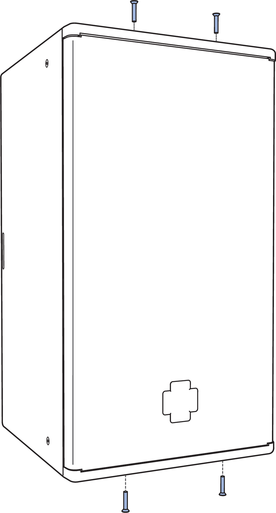
Remove ULTRA-X4x Grille Frame
Remove the four truss-head Phillips 10-32 x 3/4-inch screws holding the horn in place.
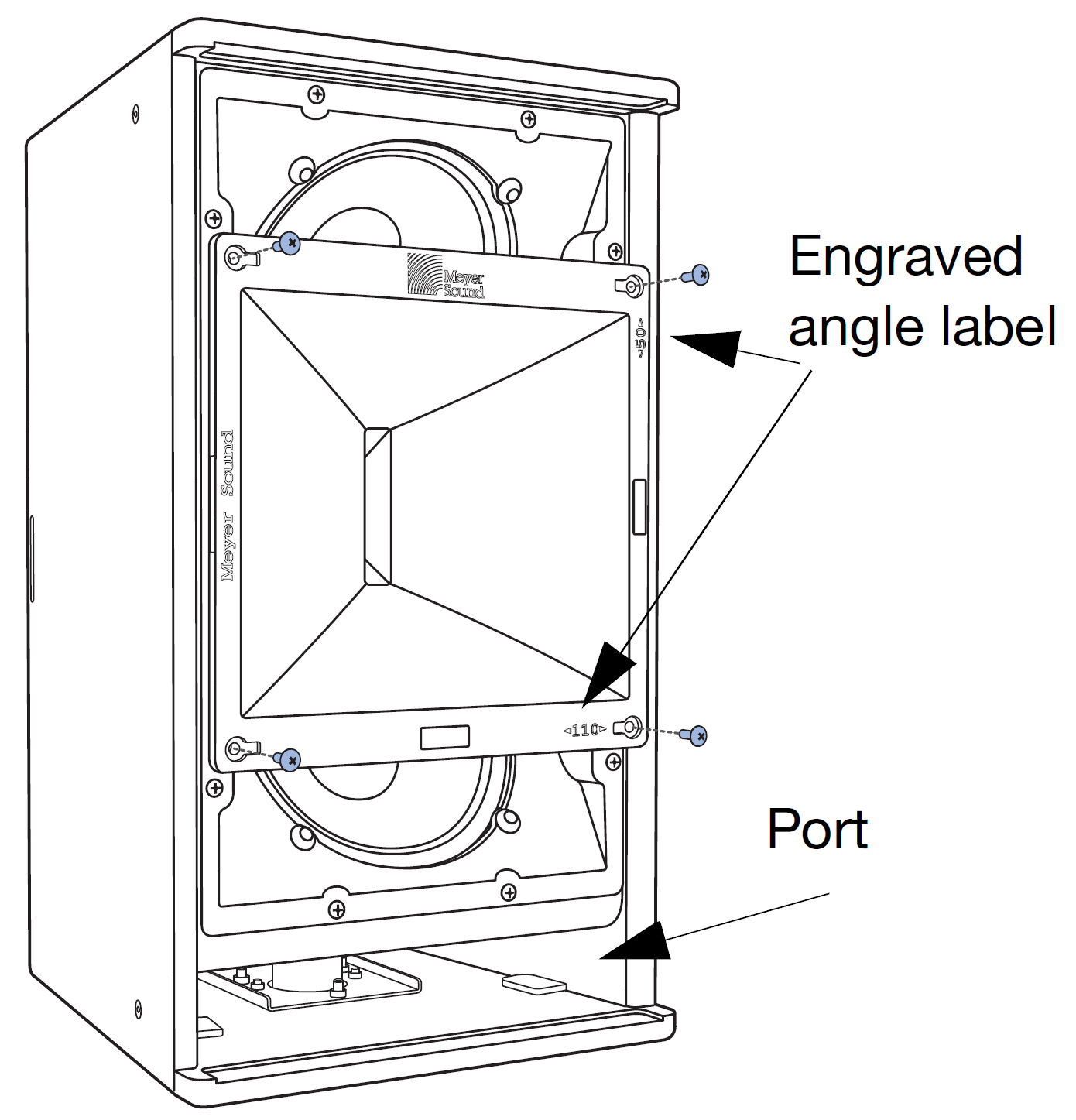
Removing Four Screws Holding the Horn in Place
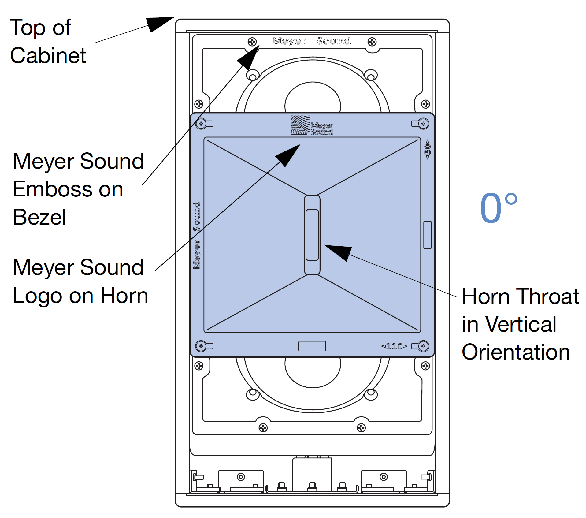
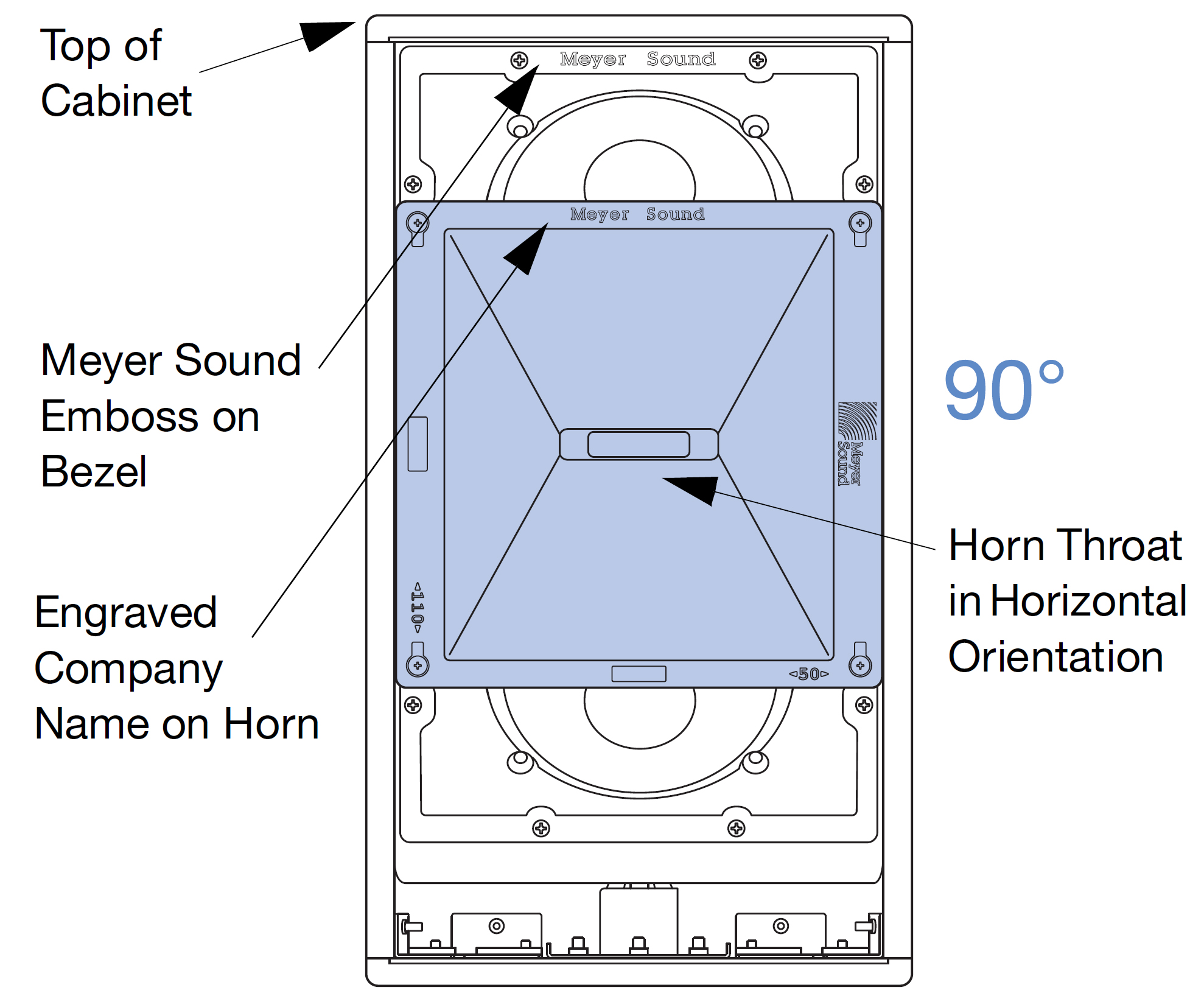
Determine the present orientation of the horn by checking the horn throat orientation when the speaker is vertical with the port at the bottom. The cabinet is vertical when the Meyer Sound Logo on the horn and on the bezel are at the top.
If the present orientation is 110° horizontal by 50° vertical (horn throat is vertical, the horn may only be rotated in the clockwise direction.
Caution
Do not pull the horn out to rotate and do not use force. It should rotate smoothly if rotated in the correct direction. The rotation angle is NOT continuous. It is limited to 90° of travel between the two orientations where the Meyer Sound emboss on the bezel lines up with either the company logo or the engraved company name on the horn.
110° horizontal by 50° vertical horn orientation
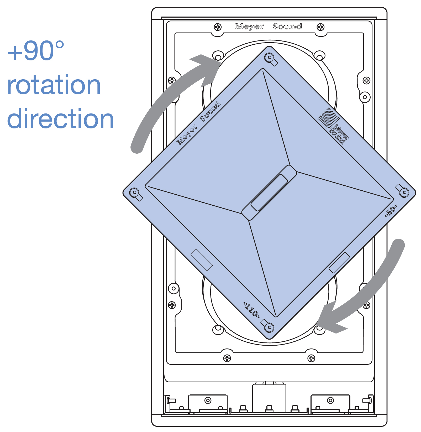
Clockwise Rotation of Horn to achieve 50° horizontal by 110° vertical horn orientation -90° rotation direction
If the present orientation is 50° horizontal by 110° vertical horn throat is horizontal, the horn may only be rotated in the counter-clockwise direction.
110° horizontal by 50° vertical horn orientation
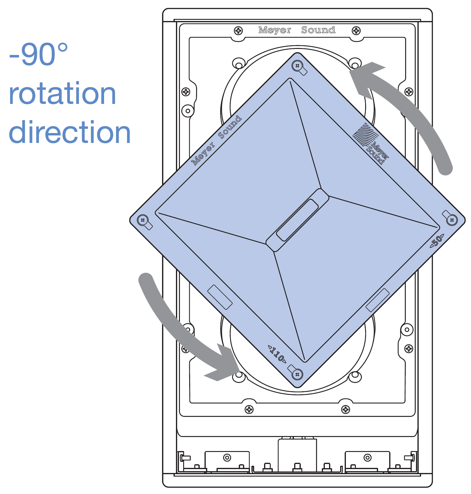
Counter-clockwise Rotation of Horn to achieve 110° horizontal by 50° vertical horn orientation
Replace the four screws removed in Step 2 to resecure the horn into position. Be sure to use the 10-32 x 3/4-inch screws. The recommended torque value for the horn screws is 19 in-lb (2.15 N·m).
Replace the grille and secure it with the four 10-32 x 1.00-inch screws removed in step 1. Meyer Sound recommends applying blue thread locker (medium strength) to screws in the leading three threads before replacing them. The recommended torque value for the grille screws is 8 in-lb (0.90 N·m).
Basic Eye Bolt Rigging
The ULTRA-X40 loudspeaker can be suspended simply using M8 eye bolts. A minimum of two eye bolts are required when suspending a single loudspeaker. The use of two eye bolts provides the added flexibility of aiming and tilting the loudspeaker for targeted coverage. Meyer Sound offers a kit with 2 black-coated M8 x 13 mm eye bolts (PN 40.287.057.01).
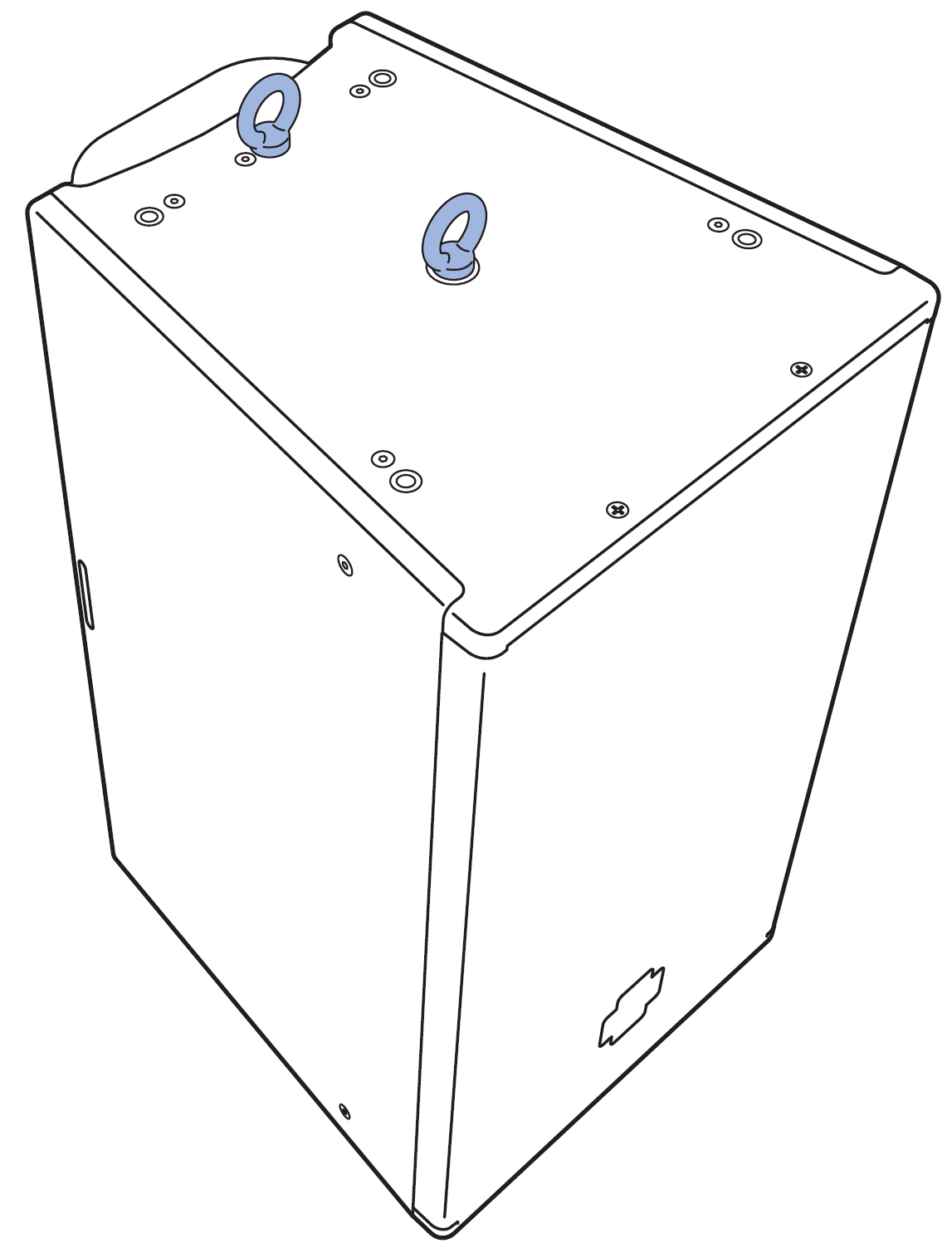
ULTRA-X40 with Two Eye Bolts
Note
Up to two ULTRA-X40 loudspeakers, oriented vertically, can be suspended with Meyer Sound eye bolts at a 5:1 safety factor. For this configuration, the top loudspeaker would have two eye bolts installed on its top and two eye bolts installed on its bottom (for connecting to the second loudspeaker), and the bottom of the upper loudspeaker requires the optional Thread Reducer M20 to M8 35MM accessory (PN 40.010.540.01).
Pole-mounting the ULTRA-X40
The MPK-POLE-35MM-M20 (PN 40.010.973.01) provides an easy and efficient way to mount the ULTRA-X40/42 on top of a 750-LFC (or 900-LFC). The MPK-POLE-35MM-M20 features all steel shafts that telescope from 36.5–60 inches and employs a secure knob to hold it in a specific position. The upper shaft includes the removable PAS-M20 Adapter Sleeve that fits the ULTRA-X40/42 internal 35 mm and M20 pole mount receptacle to make this connection more robust.
Meyer Sound offers the PAS-M20-35MM with M20 slug adapter sleeve separately (PN 40.010.974.01) for use with third-party 35 mm poles.
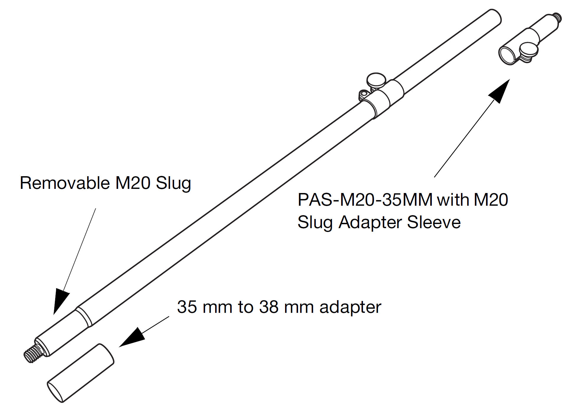
MPK-POLE-35MM-M20 kit
The MPK-POLE features a lift assist that provides approximately 40 lb of internal gas cylinder pneumatic lift. The lower end of the pole is 35 mm in diameter and has an M20 threaded lug for stability that can be removed if necessary. In addition, the MPK-POLE-35MM-M20 kit includes an adapter for converting the bottom diameter from 35 mm to 38 mm.
Locate the set screws on the Removable M20 Slug side of the pole.
Loosen the set screws using a 2.5 mm hex wrench. Do not loosen so far that the screws fall out of the pole and are lost.
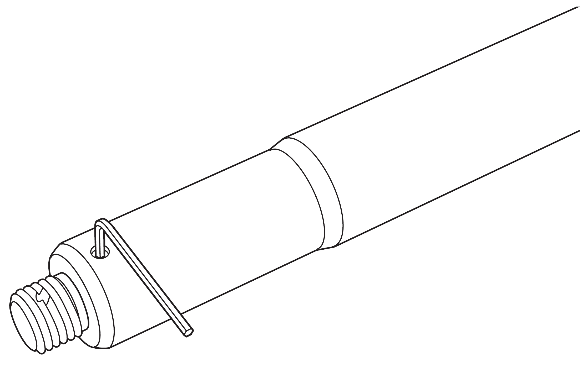
Using Hex Wrench to Loosen M20 Slug Set Screws
Loosen the M20 lug by rotating counter-clockwise (inserting a screwdriver through the lug can help with this process) and remove it.
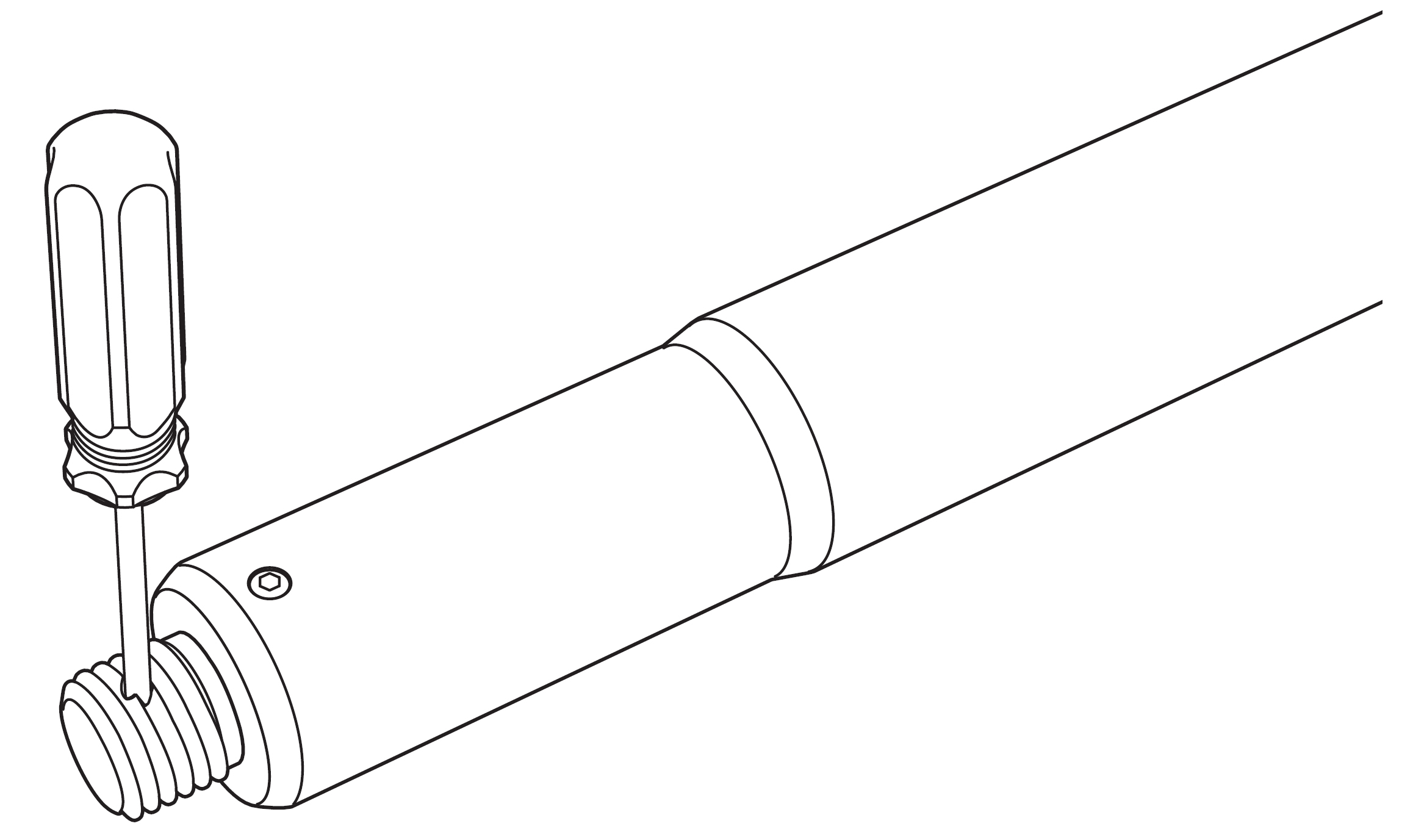
Inserting Screwdriver to Remove M20 Lug
Tighten the set screws enough to ensure they will remain in the pole.
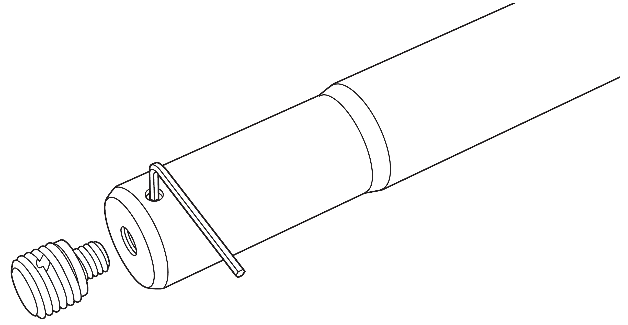
Pole with M20 Slug Removed
The pole can be used without the lug for loudspeakers that have 35 mm cup mounts without M20 threads, or the 35 mm to 38 mm adapter may be slipped onto the bottom for loudspeakers that have 38 mm cups.
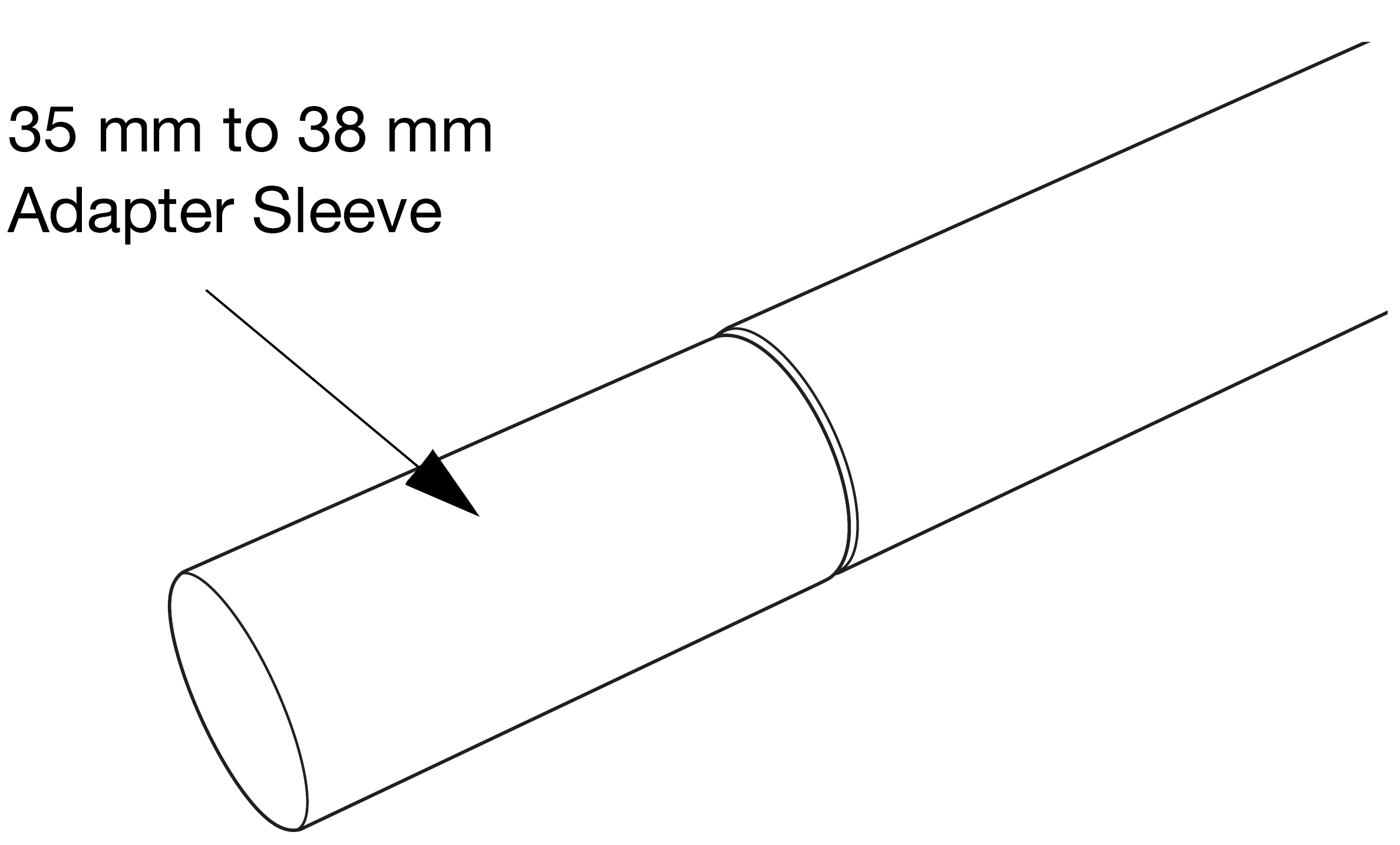
Pole with 35 mm to 38 mm Adapter Sleeve Attached
Meyer Sound recommends that a 750-LFC (or 900-LFC) be upgraded with the 35 mm/M20 internal pole mount cup (PN 40.271.016.02) for a more stable connection. This part is included with the MPK-POLE kit.
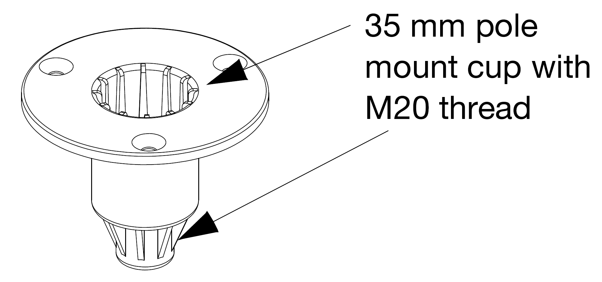
35 mm/M20 Internal Pole Mount Cup (PN 40.271.016.02)
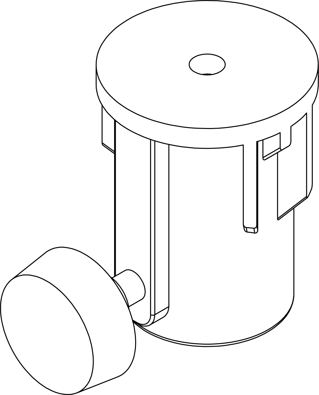
The PAS-M20-35MM Adapter is designed to securely fit into the M20 thread of the ULTRA-X4x integral pole mount. The separate knob on the adapter tightens it to the pole. (It can also be secured onto any other standard 35 mm pole.)
Tip
Use the PAS-M20-35MM knob to secure the adapter to a pole when packing the pole for travel.
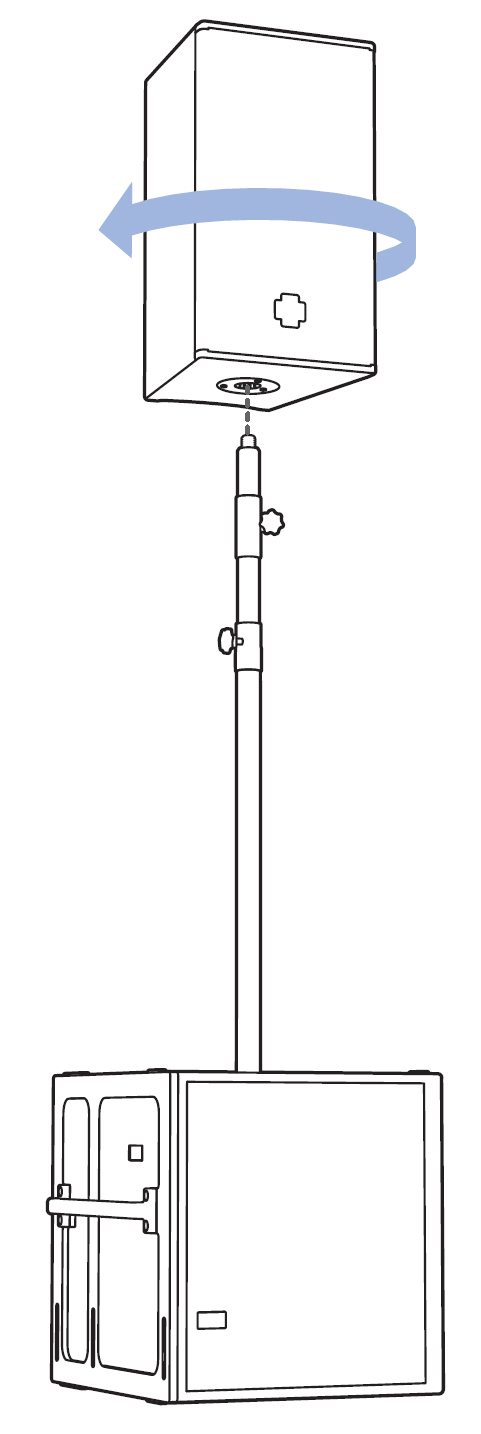
The PAS-M20-35MM may be independently (apart from the pole) threaded into the ULTRA-X4x, and then the loudspeaker/PAS-M20-35MM Adapter combination mounted onto a pole that is already secured in the subwoofer. The loudspeaker may be aimed horizontally, and the PAS-M20-35MM knob tightened.
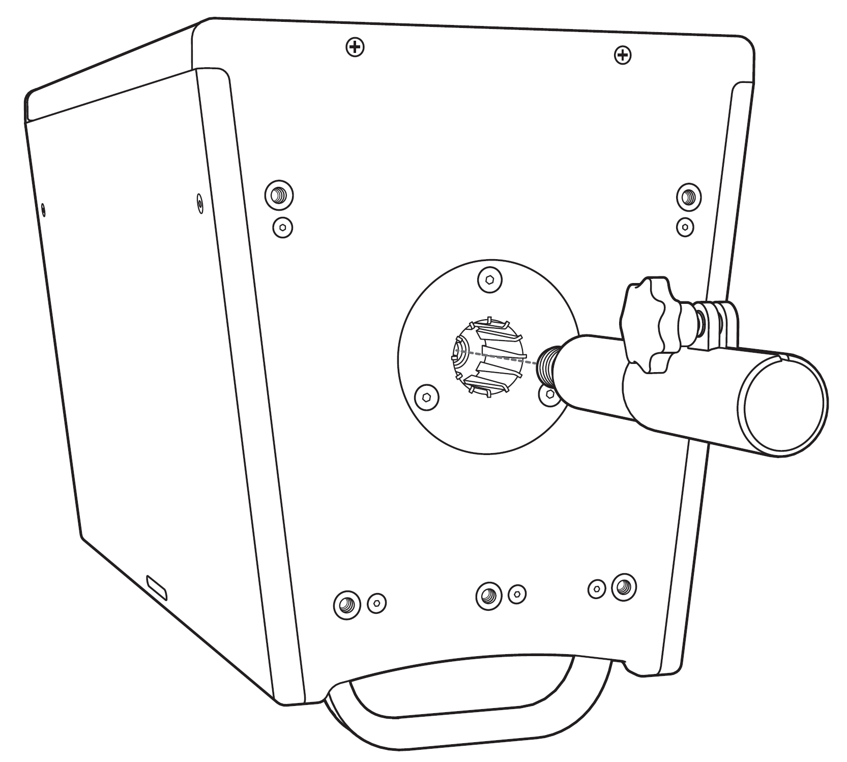
Inserting the PAS-M20-35MM Adapter Independently
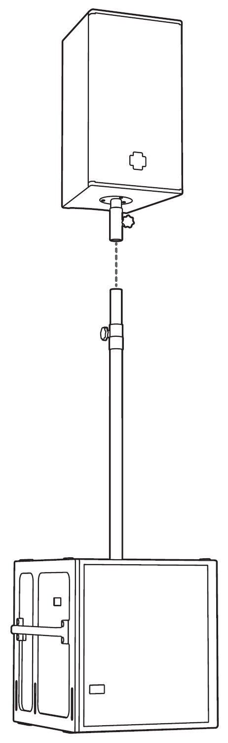
Settling Loudspeaker/Adapter Combination onto Pole
Alternatively, the PAS-M20-35MM Adapter can be secured to the pole first and then the two items jointly inserted into the subwoofer mounting cup and tightened. The loudspeaker may then be lifted onto the PAS-M-20-35MM adapter and rotated until the M20 thread is tightened within the loudspeaker’s mounting cup. Loosening the PAS-M20-35MM Adapter knob after the loudspeaker/ PAS-M20-35MM Adapter M8 connection is secure can again facilitate horizontal aiming of the loudspeaker.
Rotating Loudspeaker onto PAS-M20-35MM
Note
The ULTRA-X40/42 integral pole mount adapter will receive any 35mm pole shaft. However, the use of the Meyer Sound MPK-Pole-35MM-M20 and the PAS-M20-35MM is recommended to make a more robust connection.
When using a third-party pole, make sure the pole is designed to support the total weight of the ULTRA-X40/42 loudspeaker and observe all safety precautions specified by the pole manufacturer.
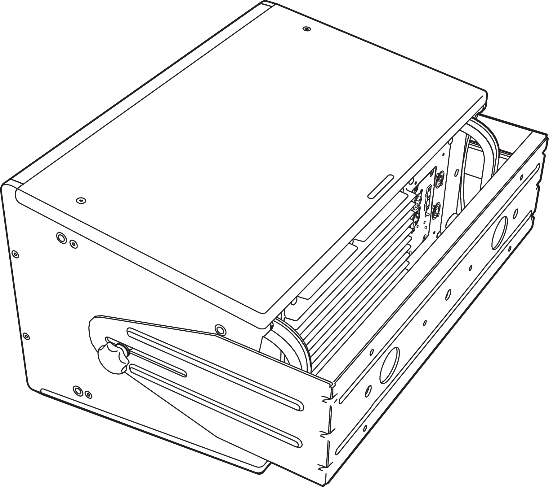
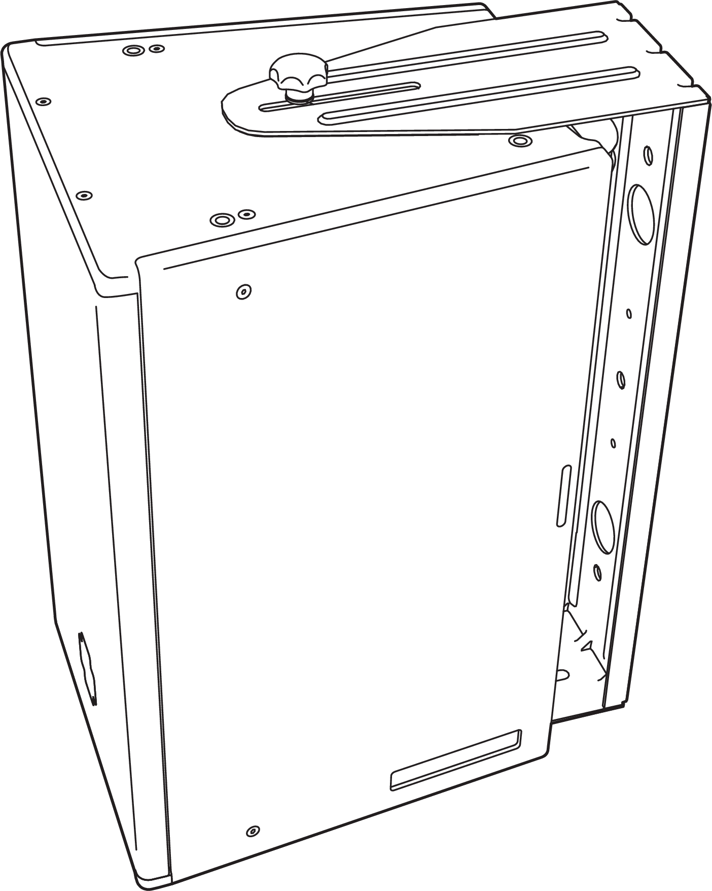
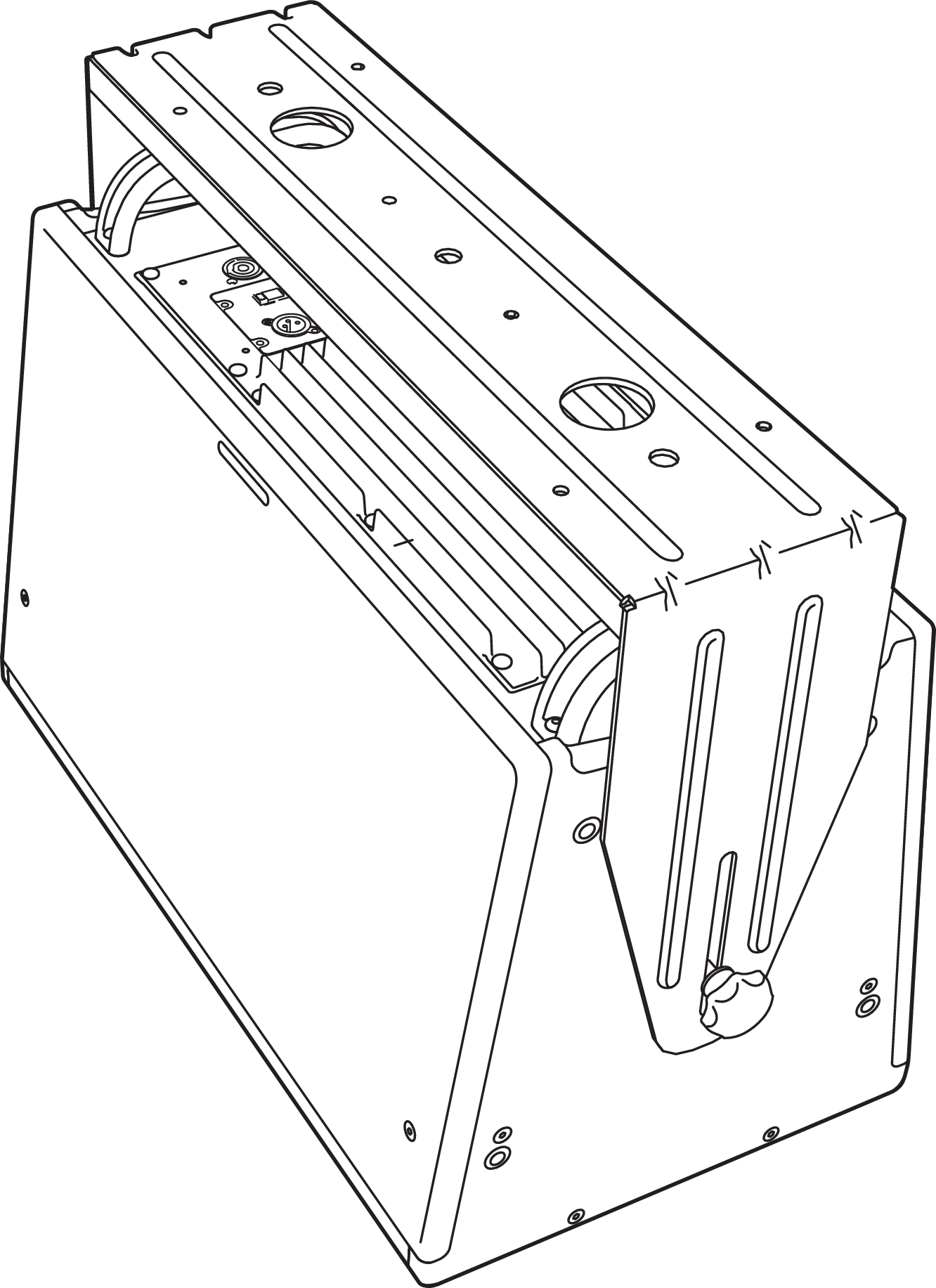
MYA-X40 Mounting Yoke
The MYA-X40 mounting yoke (PN 40.287.039.01) suspends a single ULTRA-X40/42 loudspeaker and supports a wide range of horizontal and vertical adjustments. The yoke attaches to the top of the loudspeaker using three of the six rig nuts. The kit includes three M8 bolts and three M8 knobs. The bolts are recommended for fixed installations. A hanging clamp and steel safety cable (not included) are required to suspend the MYA-X40 mounting yoke.
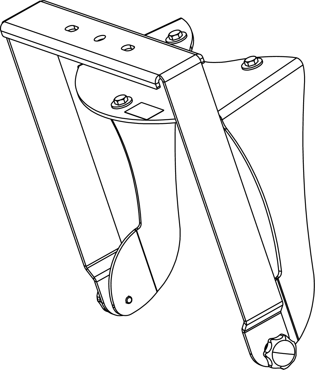
MYA-X40 Mounting Yoke
ULTRA-X40 in the MYA-X40 Yoke Mount
Note
The top bar of the MYA-X40 mounting yoke accommodates hanging clamps with standard 1/2-inch or 12 mm bolts.
Caution
THE MYA-X40 Yoke is rated for a single loudspeaker. Never hang a second loudspeaker or other object underneath.
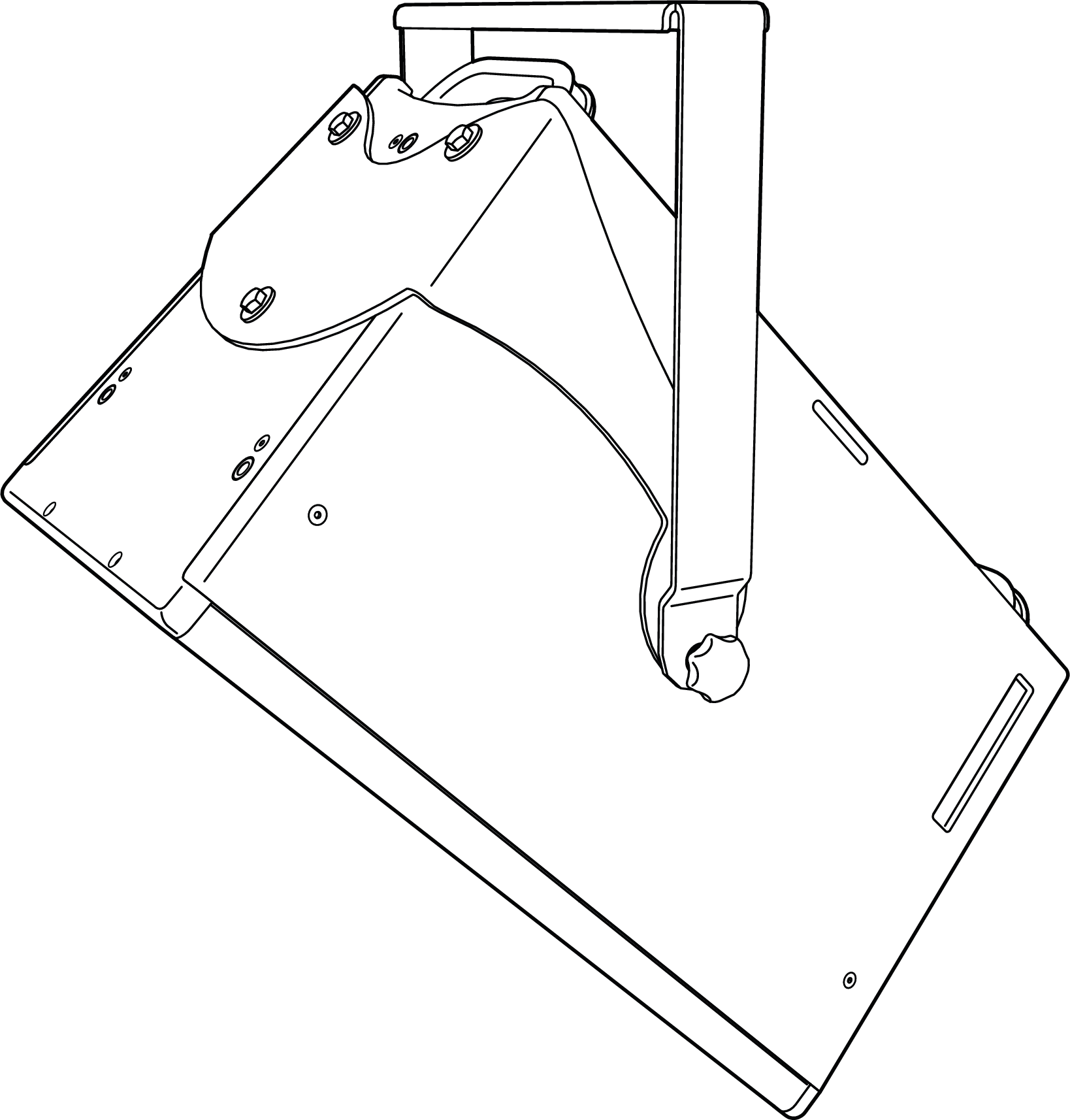
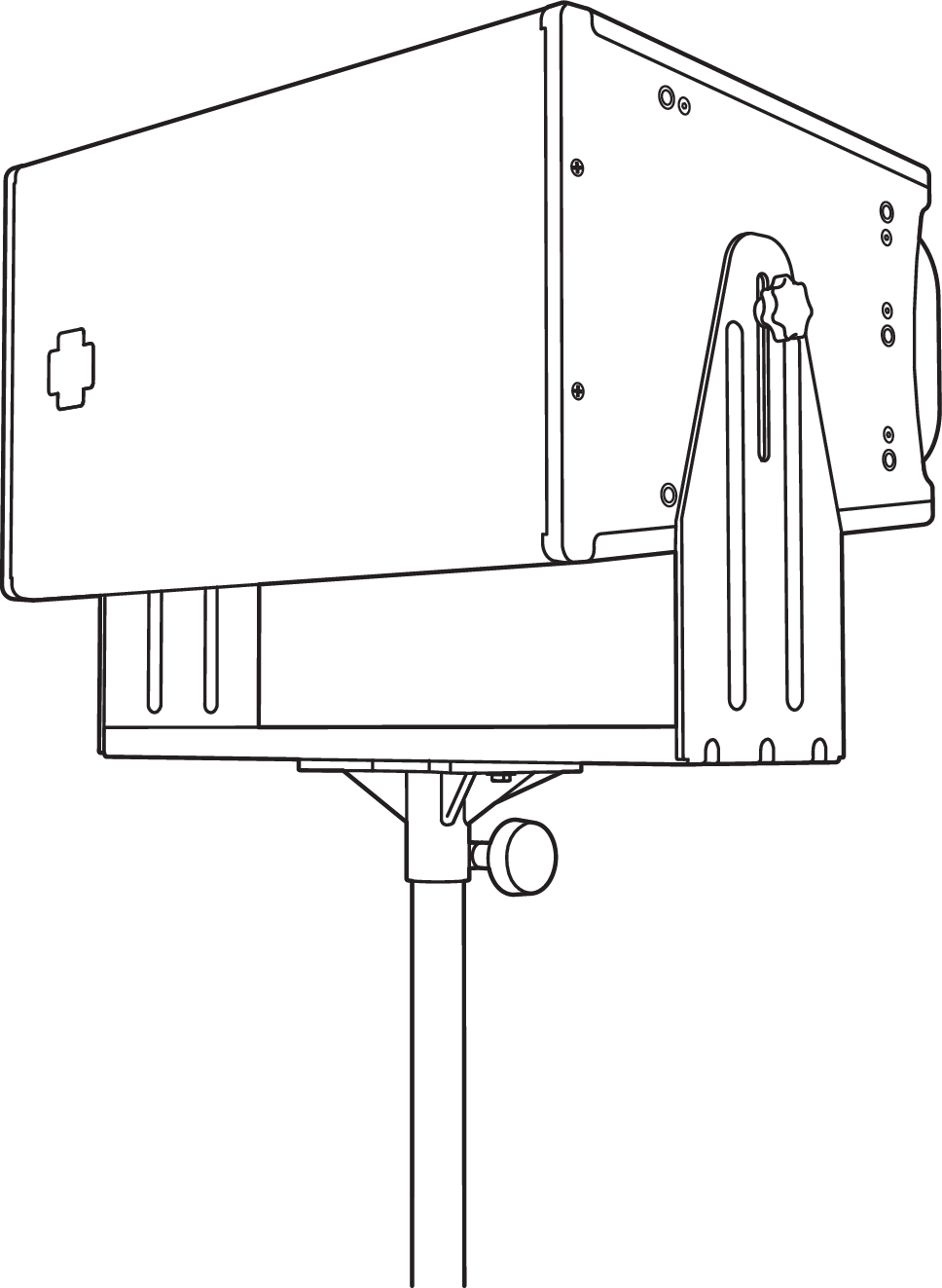
In addition, the yoke may be mounted onto a 35 mm pole using the optional MSA-STAND Adapter Cup 35MM (PN 40.086.013.01) to facilitate easy panning and tilting.
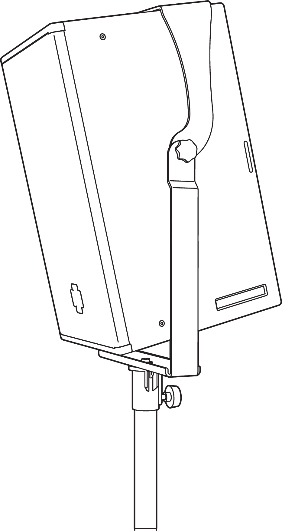
40: ULTRA-X40 in the MYA-X40 Yoke Mount on Pole using the optional MSA-STAND Adapter Cup 35MM
Optional MSA-STAND Adapter Cup 35MM
MUB-X40 U-bracket
THE MUB-X40 U-BRACKET
The MUB-X40 U-Bracket (PN 40.287.055.01) allows a single ULTRA-X40/42 loudspeaker to be mounted to a wall in either vertical or horizontal orientations to the ceiling, onto the floor, or on top of a pole. Mounting the MUB-X40 U-Bracket onto a pole requires a pole mount adapter, such as the 35MM pole stand adapter or the MSA-STAND adapter cup. The MUB-X40 kit includes two M8 bolts, two M8 knobs, and a 35 mm diameter, M20 to M8 thread size reducer. The bolts are recommended for fixed installations.
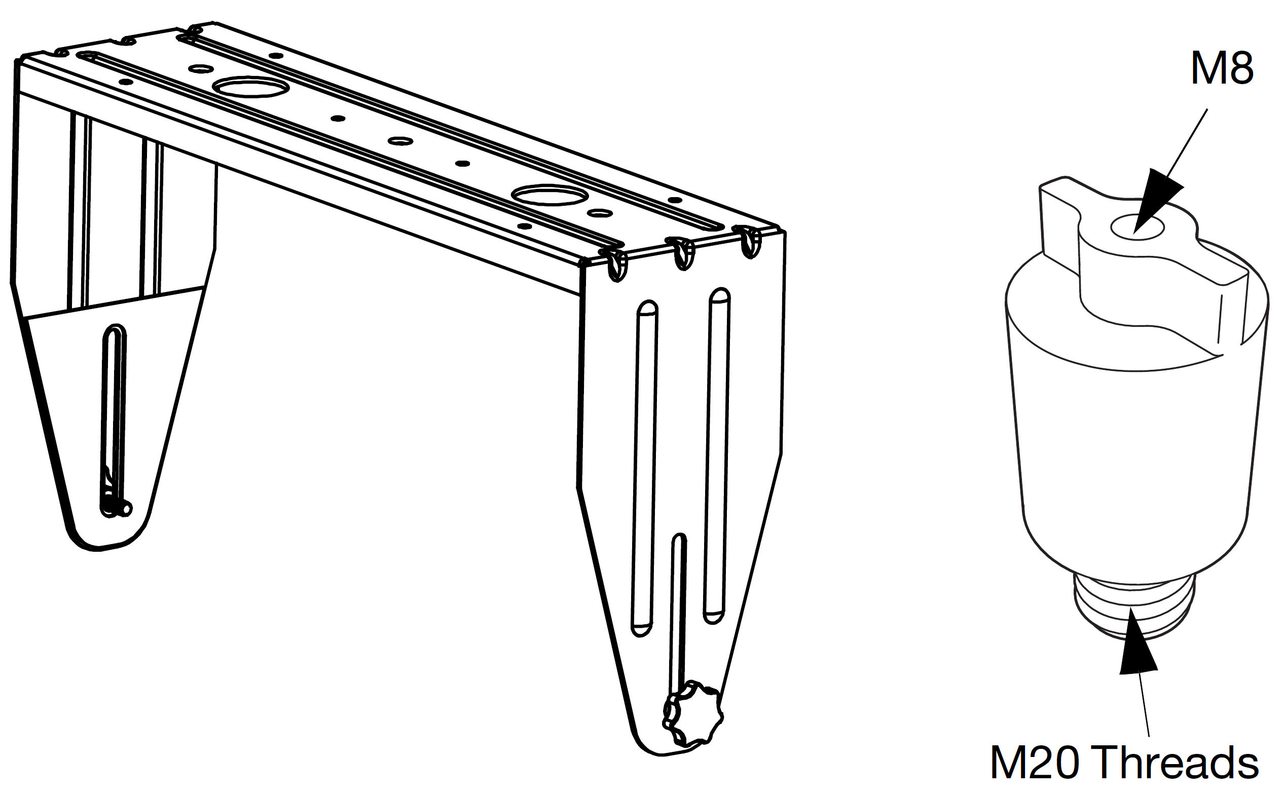
MUB-X40 U-Bracket (left) with Thread Reducer M20 to M8 (35MM) (right)
The reducer is needed to convert the cabinet's bottom built-in pole mount M20 internal threads to M8 size to install the MUB-X40. The Thread Reducer M20 to M8 35MM can be installed and removed without the need of tools, and it can be conveniently transported on the M8 stud located on one side of the MUB-X40. The thread reducer is also available separately (PN 40.010.540.01).
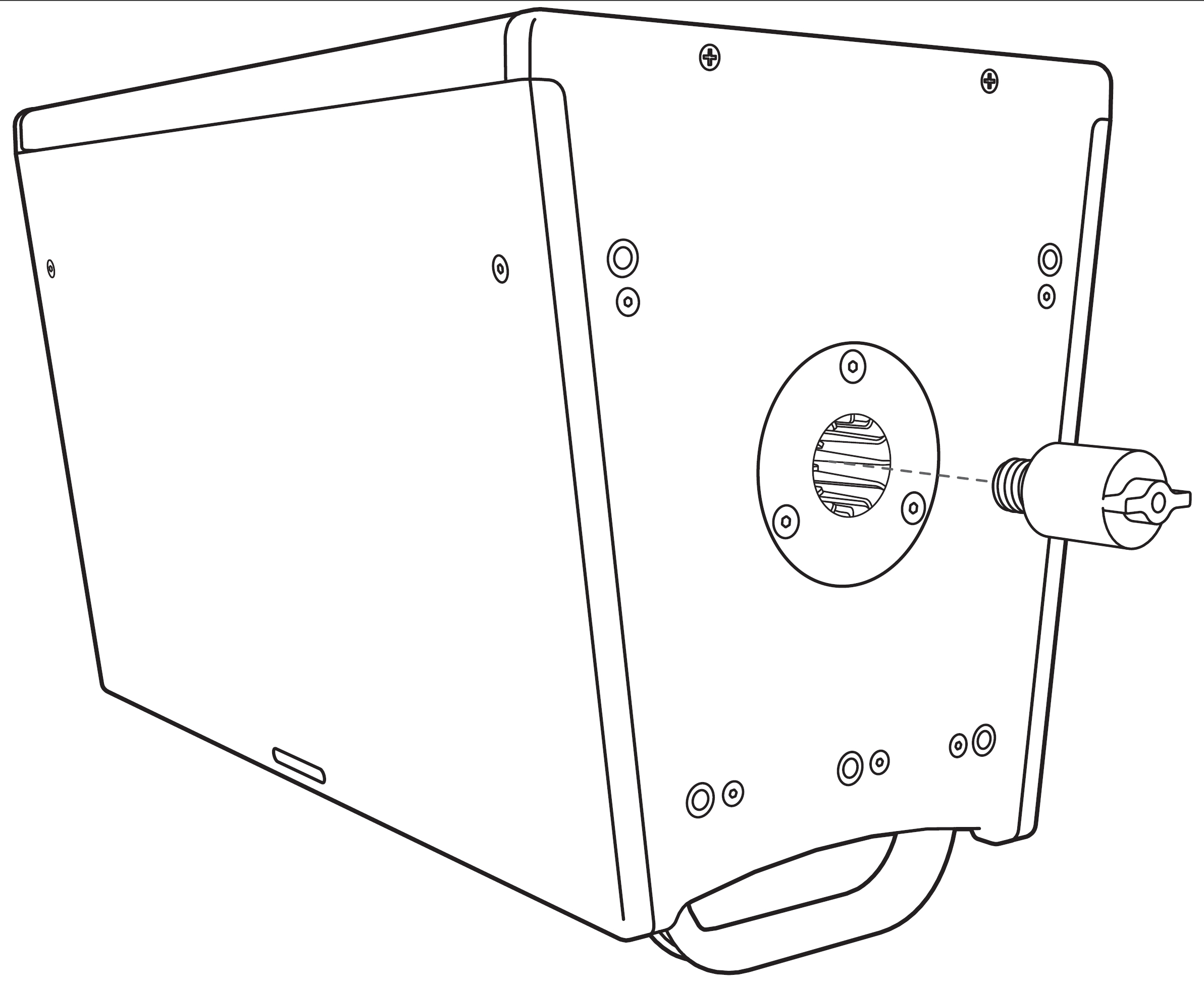
Converting ULTRA-X40/42 Cabinet to M8 size with Thread Reducer M20 to M8 (35 MM).
MUB-X40 U-Bracket Load Ratings
One ULTRA-X40/42 can be safely mounted with the MUB-X40 U-Bracket at a 5:1 safety factor.
When mounting an ULTRA-X40/42 with the MUB-X40 U-Bracket, the U-Bracket must be secured to the mounting surface with one of the configurations shown in [→ _bookmark72]Table 6 (for hole locations, see [→ _bookmark73]Figure 44 on page 36.
Hole | Safety Factor |
|---|---|
1/2-inch center hole | 5:1 |
Two 1/2-inch outer holes | 5:1 |
All four 1/4-inch corner holes | 5:1 |
Two 1/4-inch center holes | Not rated for mounting. These holes are for pole-mounting the MUB-X40 using a pole-mount adapter. |
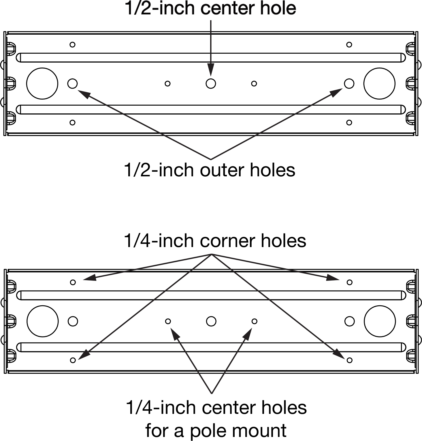
MUB-X40 Mounting Hole Configuration Locations
MUB-X40 Wall Mount, Horizontal
MUB-X40 Wall Mount, Vertical
MUB-X40 Ceiling Mount
MUB-X40 Pole Mounted using the 35MM Pole Stand Adapter
35MM Pole Stand Adapter
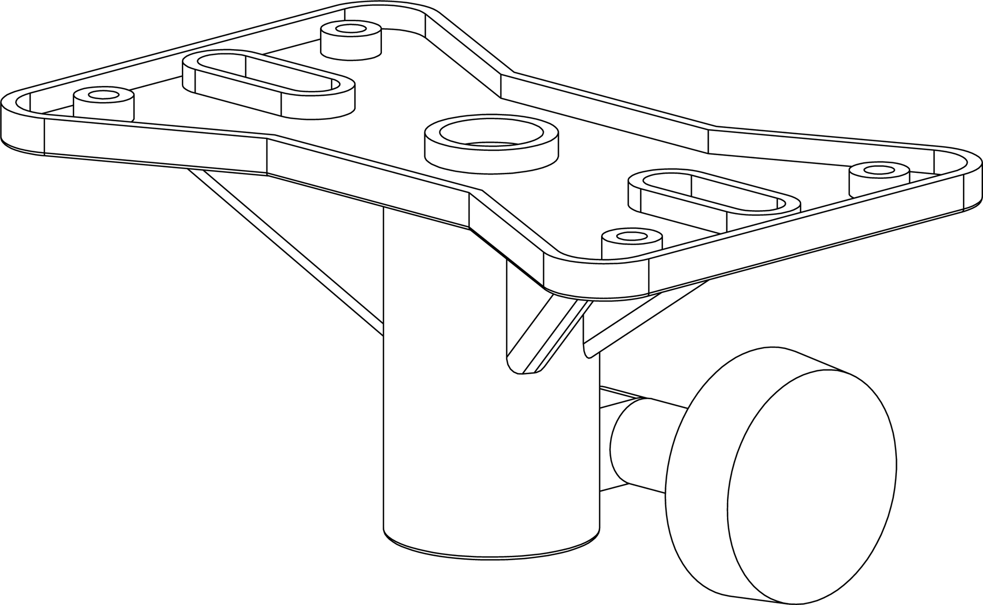
MTC-X40 Top Channel Kit
The MTC-X40 Top Channel kit (PN 40.287.130.01) includes a pinnable link in a channel that mounts directly to the ULTRA-X40/42 rig nuts or into an MCP plate. It supports pick-up of up to three ULTRA-X40/42 loudspeakers from a single point using the two included lock pins and 3/8-inch black shackle. The MTC-X40 Top Channel attaches to the speaker or to an MCP50-X40 or MCP70-X40 plate with two M8 bolts.
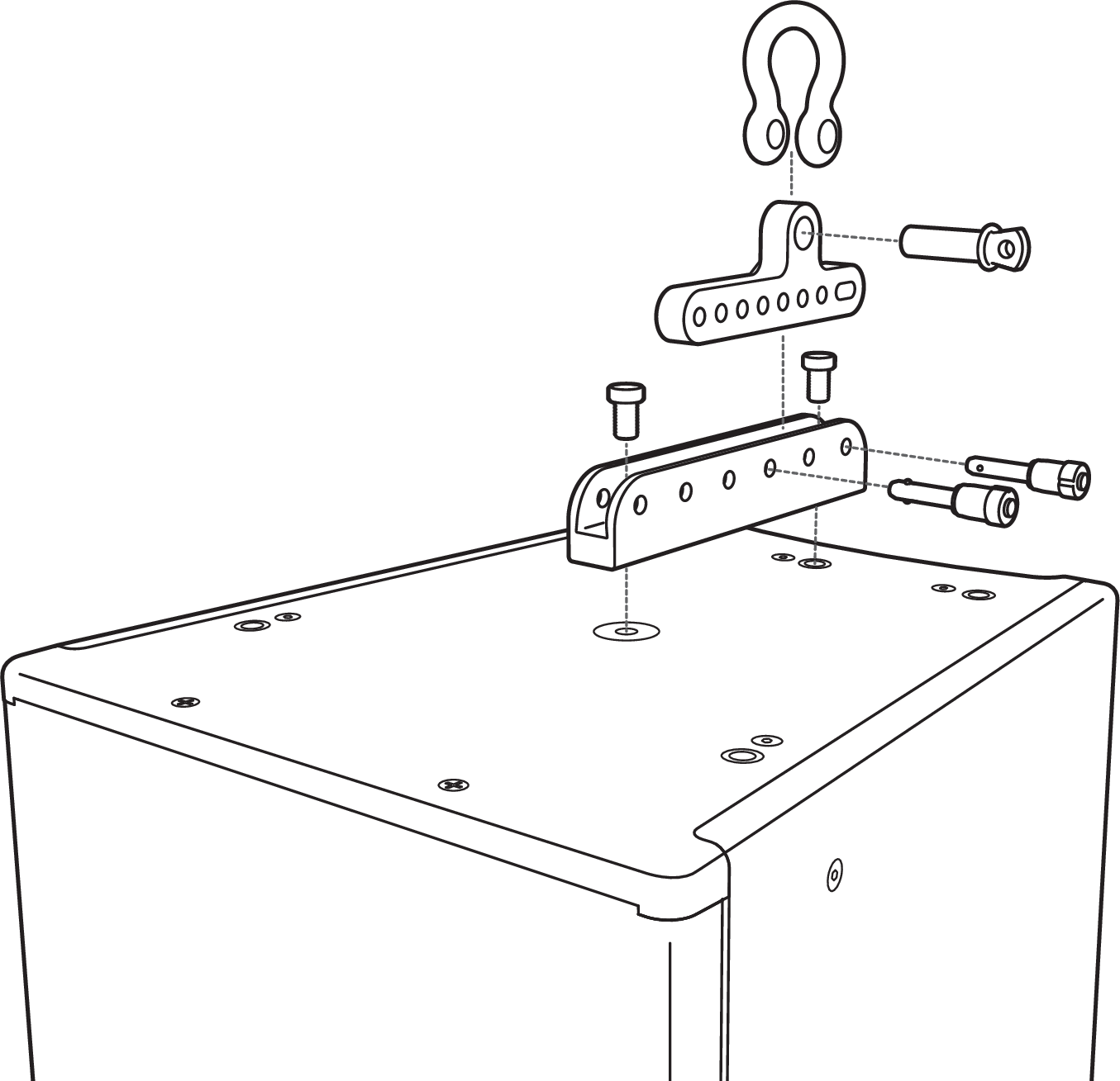
MTC-X40 Top Channel Kit Installed at Top of Cab
The versatile configuration of the channel and link, with the ability to slide the pinnable link within the channel, facilitates 9 different top pickup points. This flexibility allows for approximately +10° to –30° tilting of a loudspeaker that hangs from a single point.
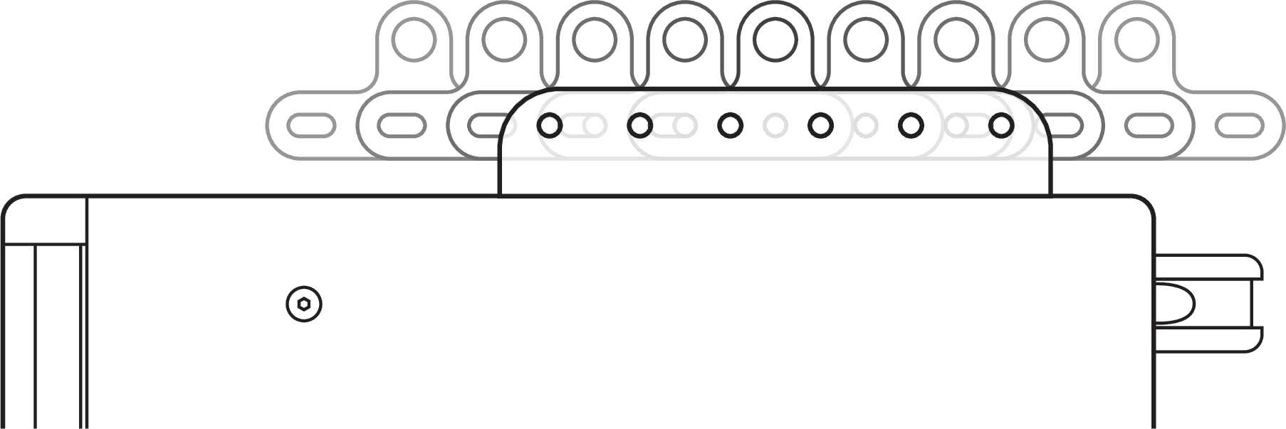
MTC-X40 Pickup Points
Using multiple versions of this kit (together with the Thread Reducer M20 to M8 35MM part sold separately) allows the user to create two- and three-loudspeaker angled configurations.
Note
Using multiple MTC-X40 Top Channel Links in a multi-loudspeaker configuration requires the use of the Thread Reducer M20 to M8 35MM on the bottom of each loudspeaker to which an MTC-X40 will attach.
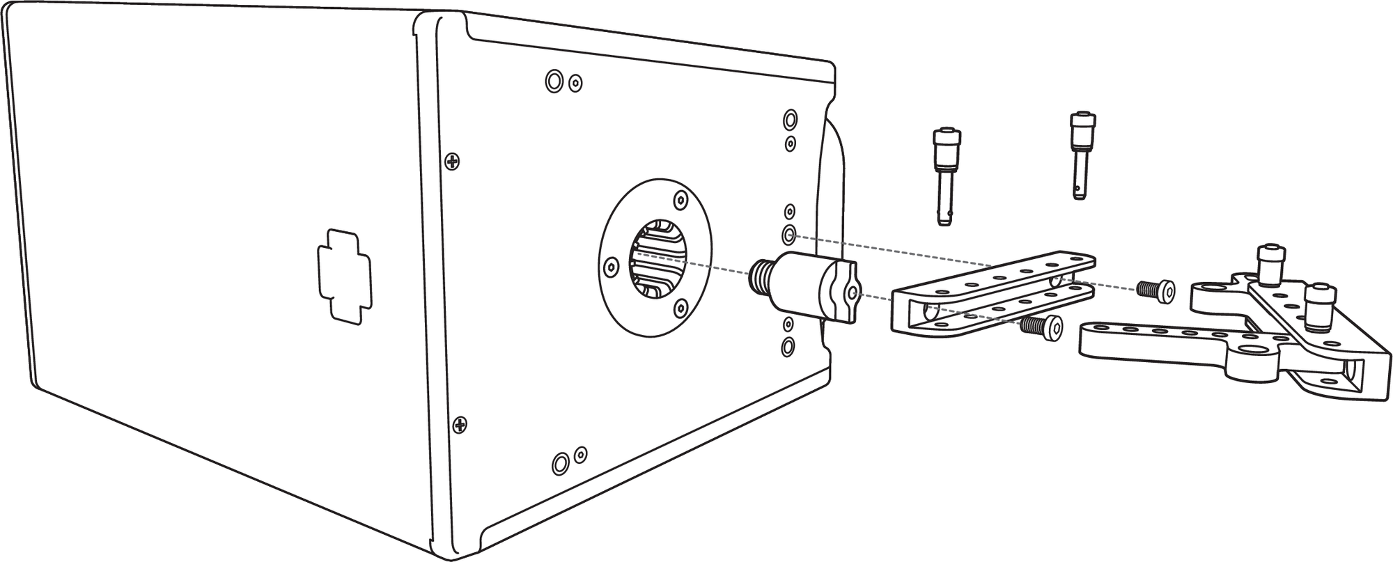
Attaching MTC-X40 to Bottom
In the example figure below, one Thread Reducer M20 to M8 35MM is required for the upper loudspeaker cabinet.
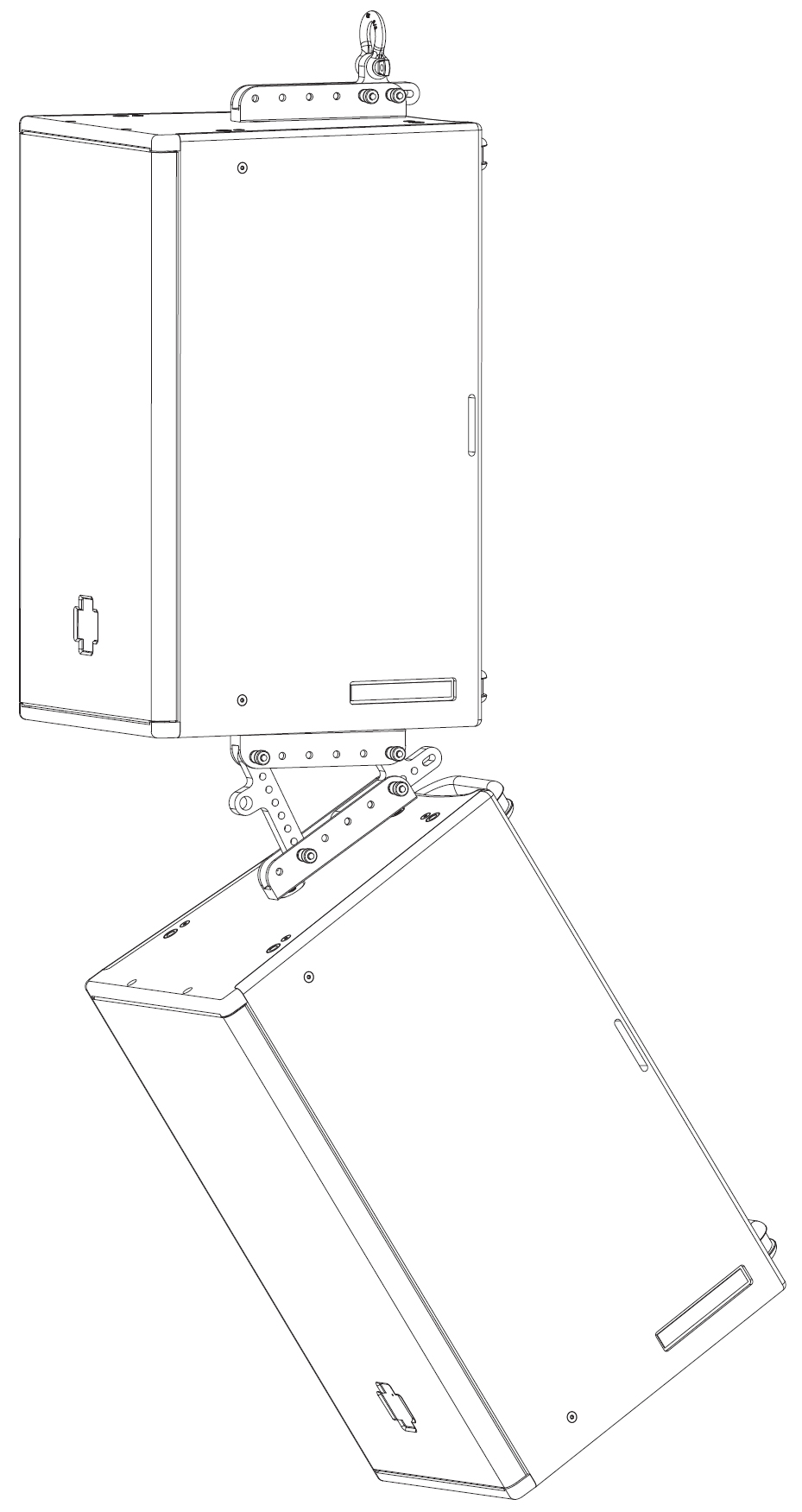
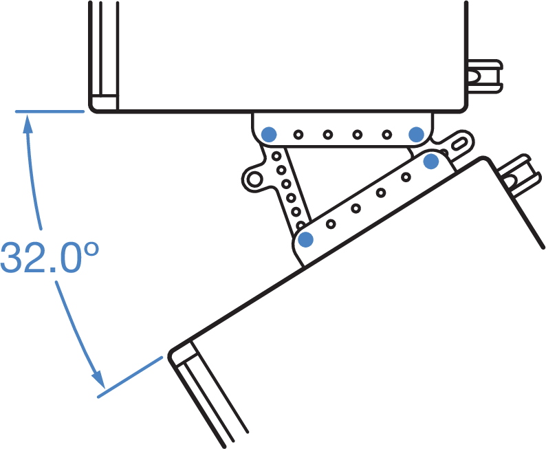
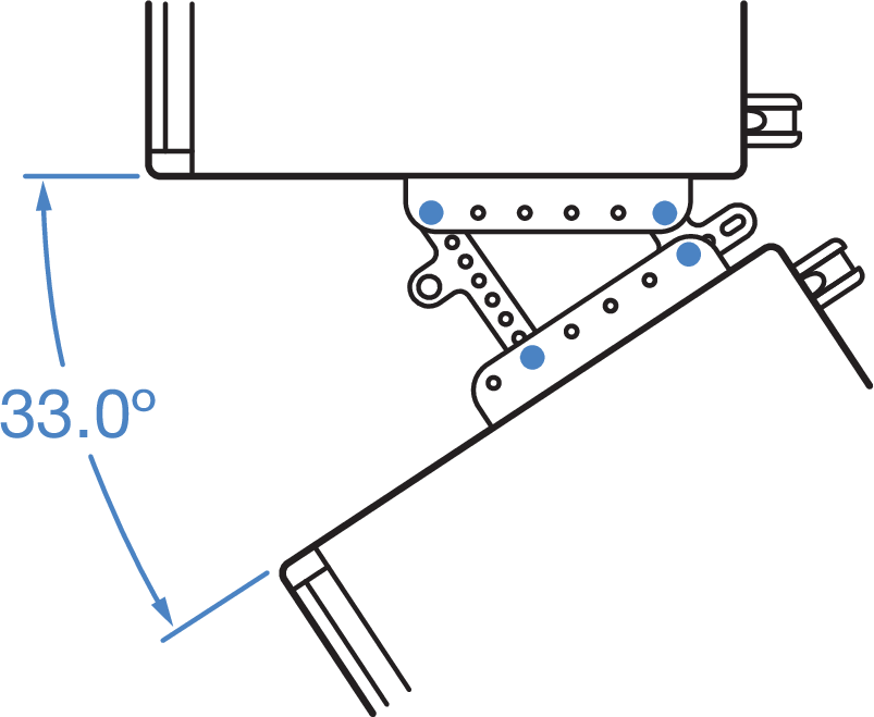
Example of two MTC-X40 Top Channels linking speakers at a 33° angle with a third MTC-X40 channel on top for pickup point.
Caution
A three-loudspeaker cluster using multiple MTC-X40 Top Channel Links requires the use of a pullback cable attached to an MTC-X40 Top Channel Link that is secured to the bottom of the lowest loudspeaker, as shown in the figure below.
Note
In the figure below, three Thread Reducer M20 to M8 35MM parts are required—one for each loudspeaker cabinet bottom.
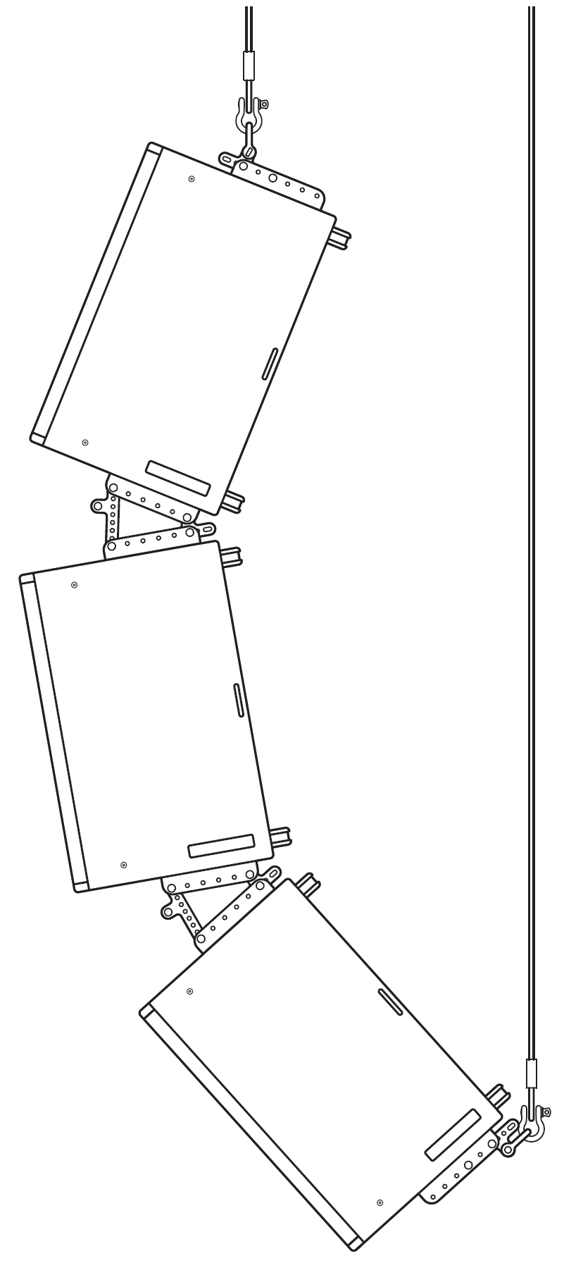
Three-ULTRA-X40/42 Cluster using MTC-X40s requires pullback cable
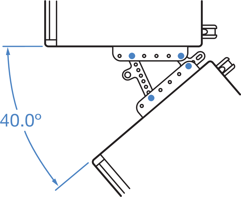
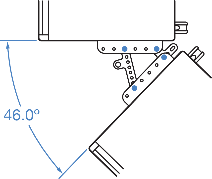
Channel and Link Splay Angles | |
|---|---|
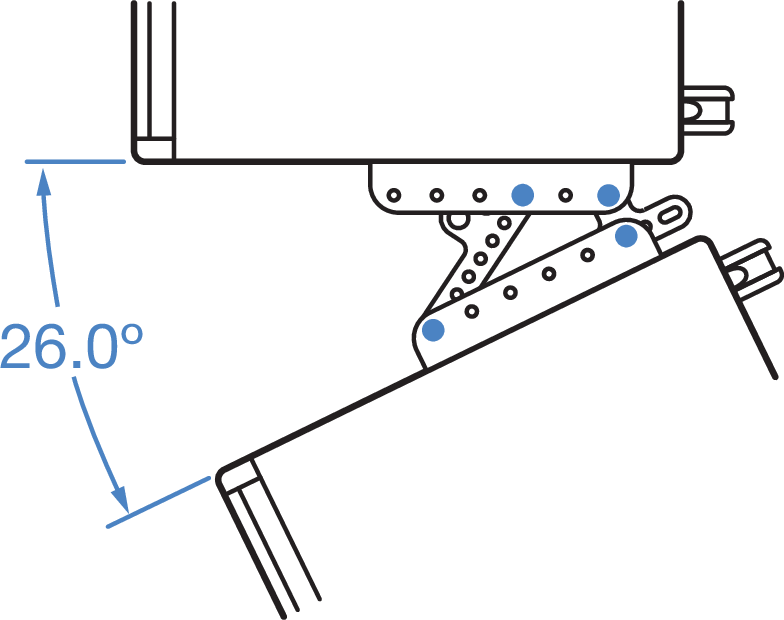 | 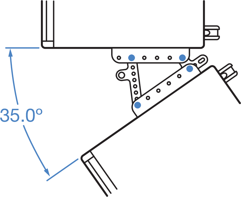 |
 |  |
 |  |
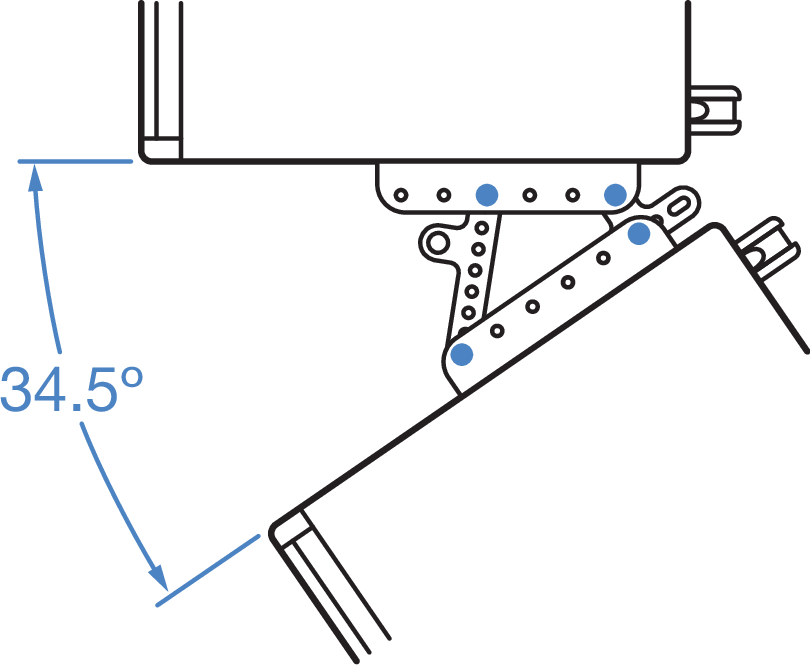 | 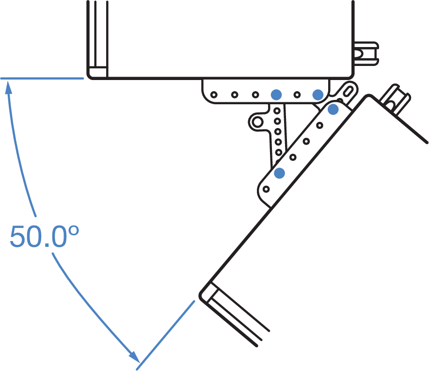 |
MCP50-X40 and MCP70-X40 Cluster Plates
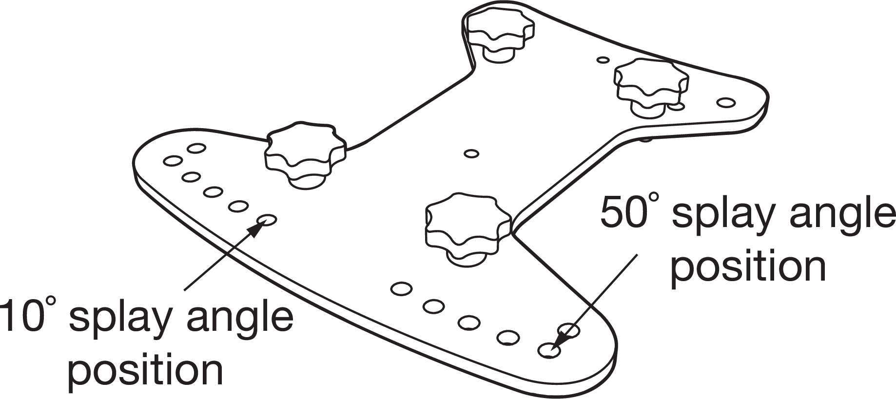
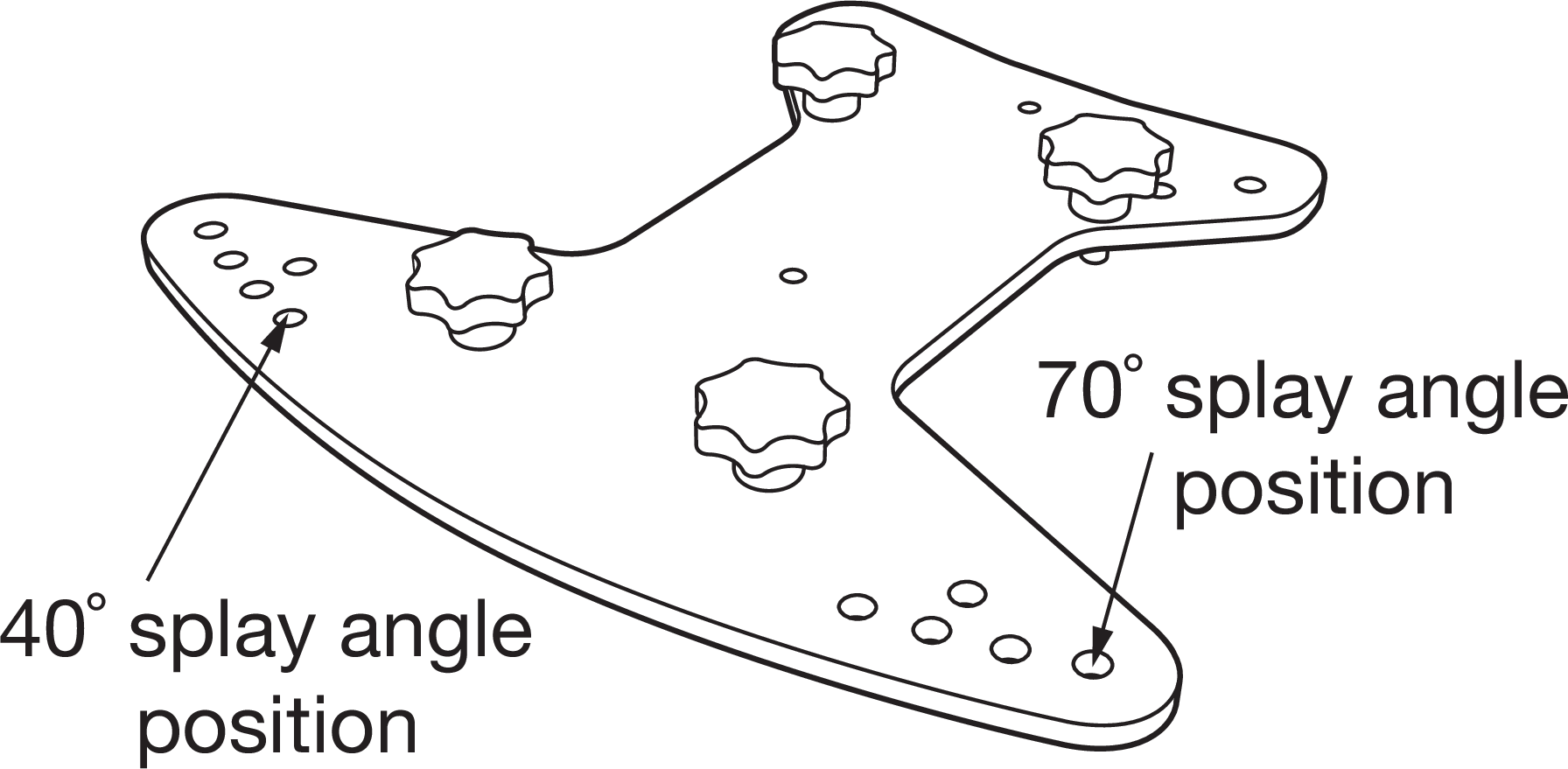
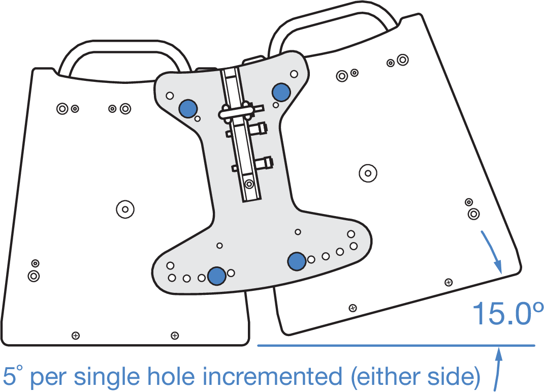
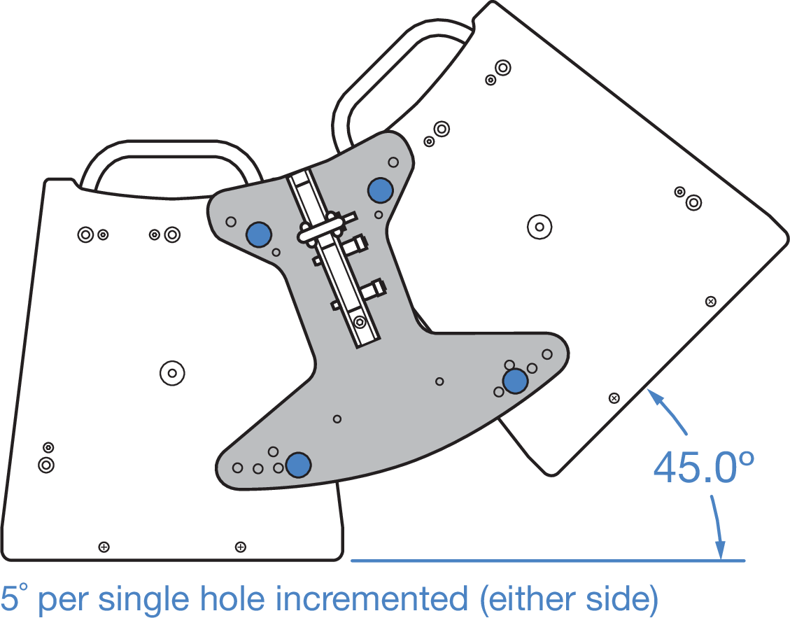
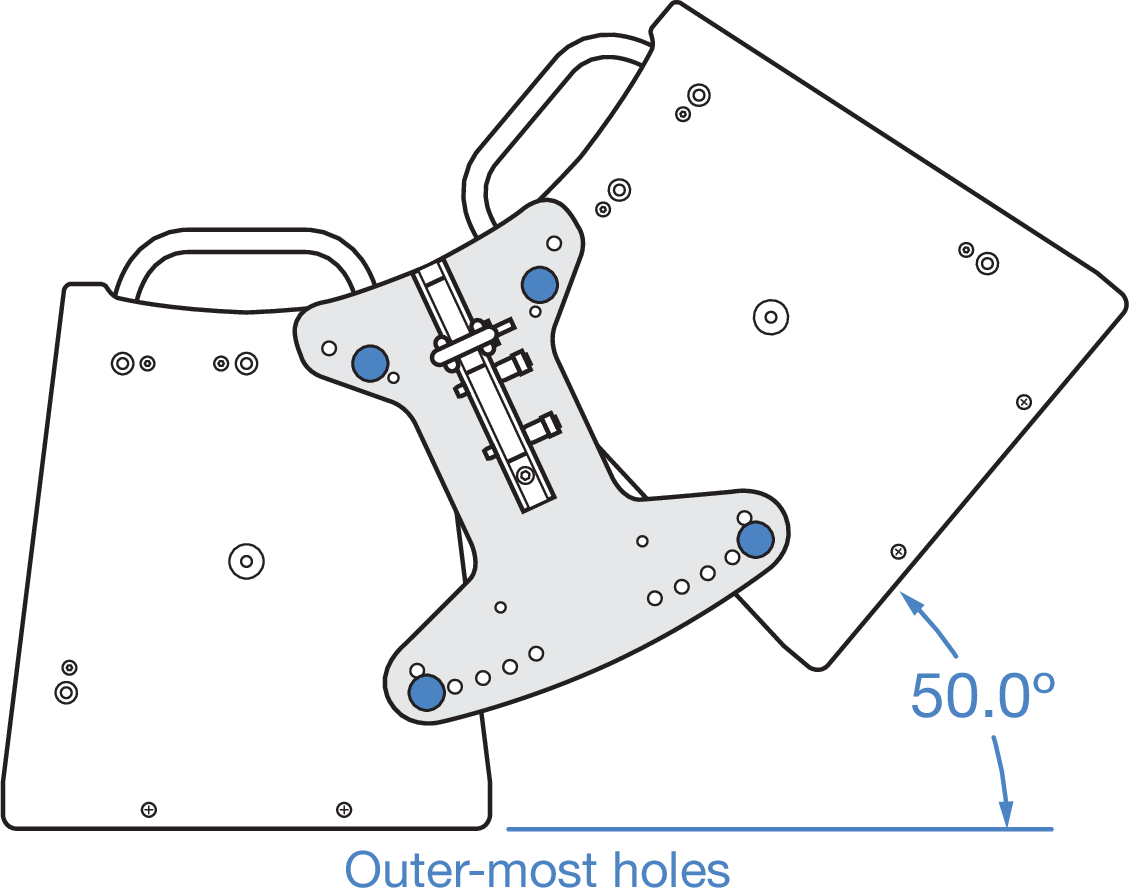
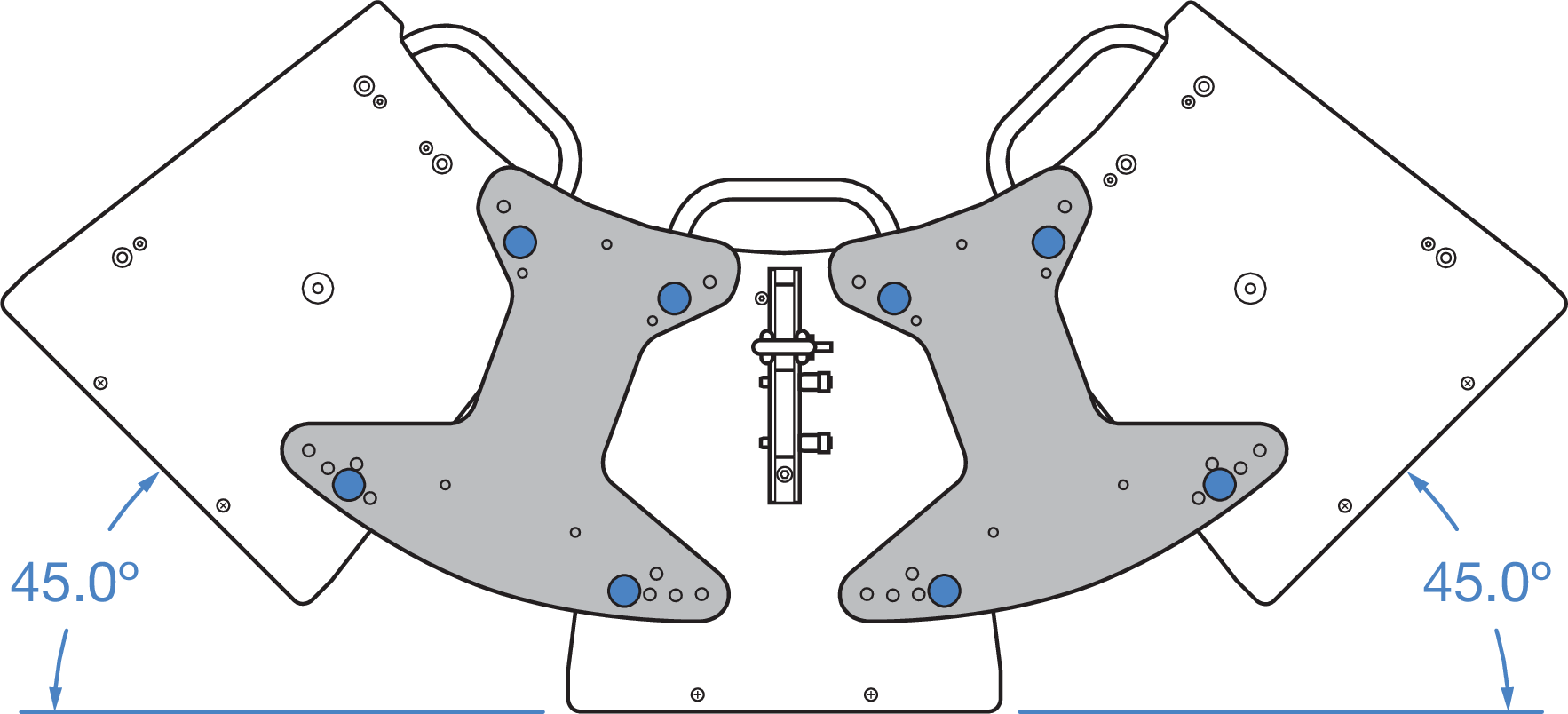
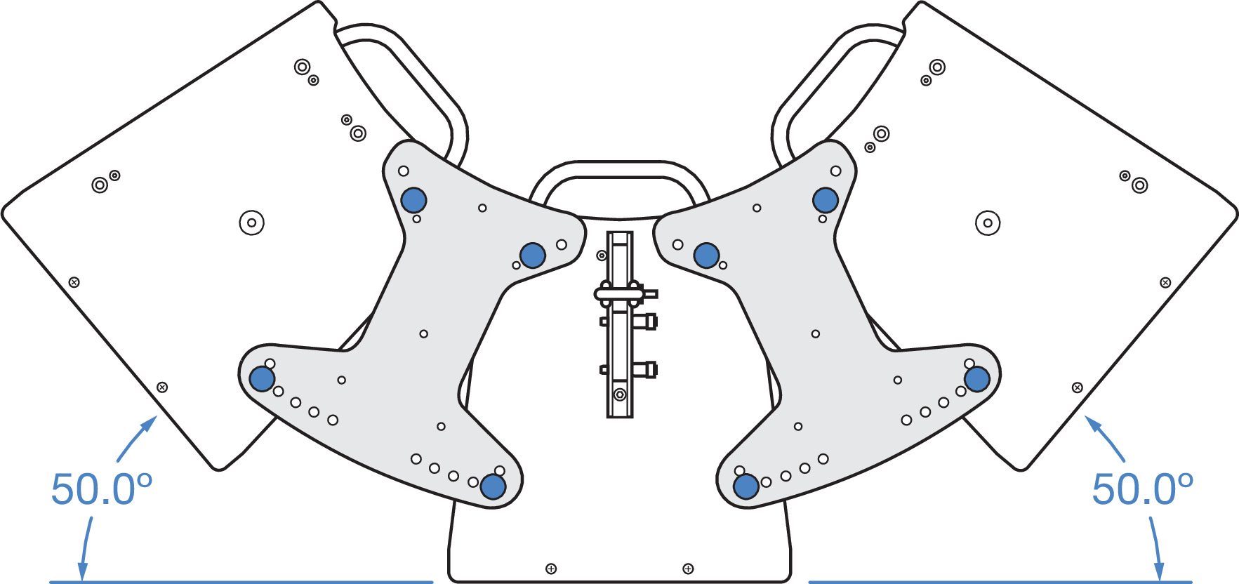
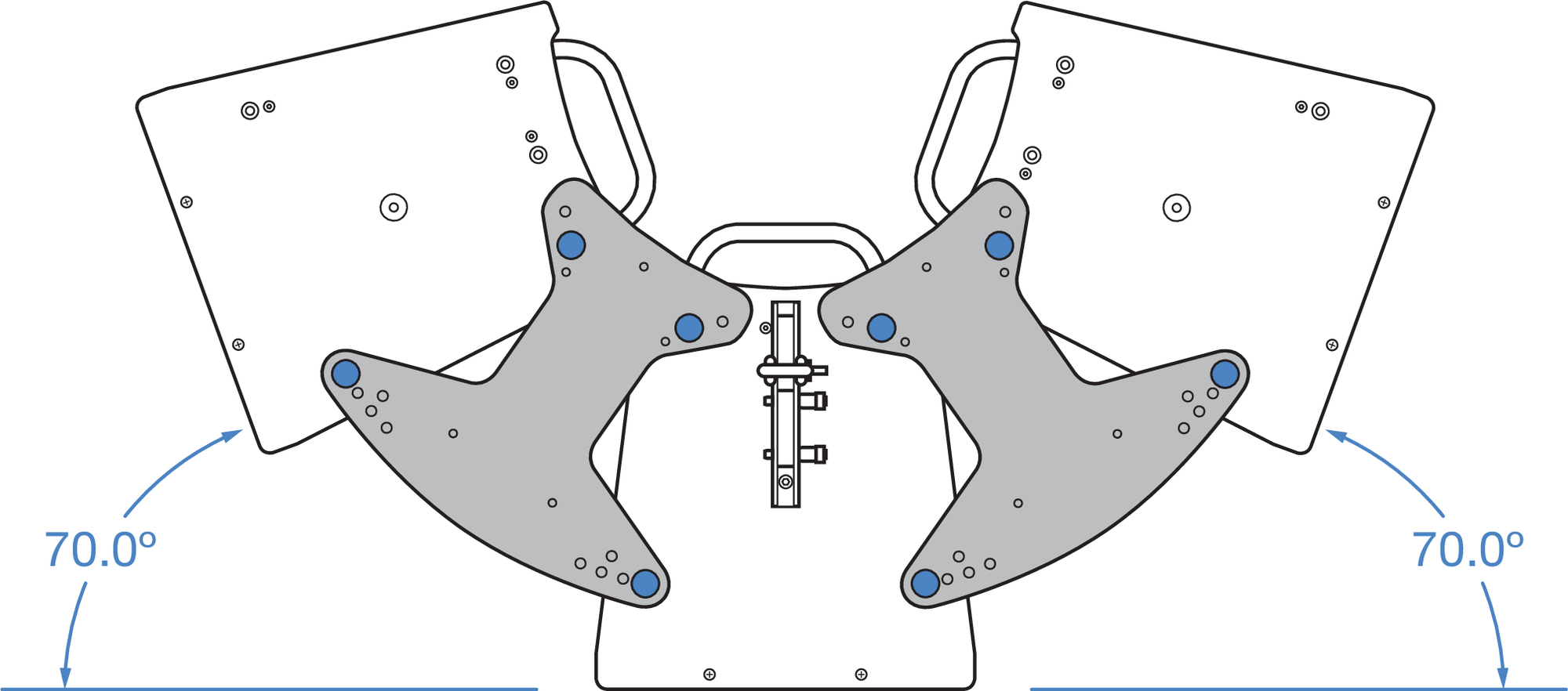
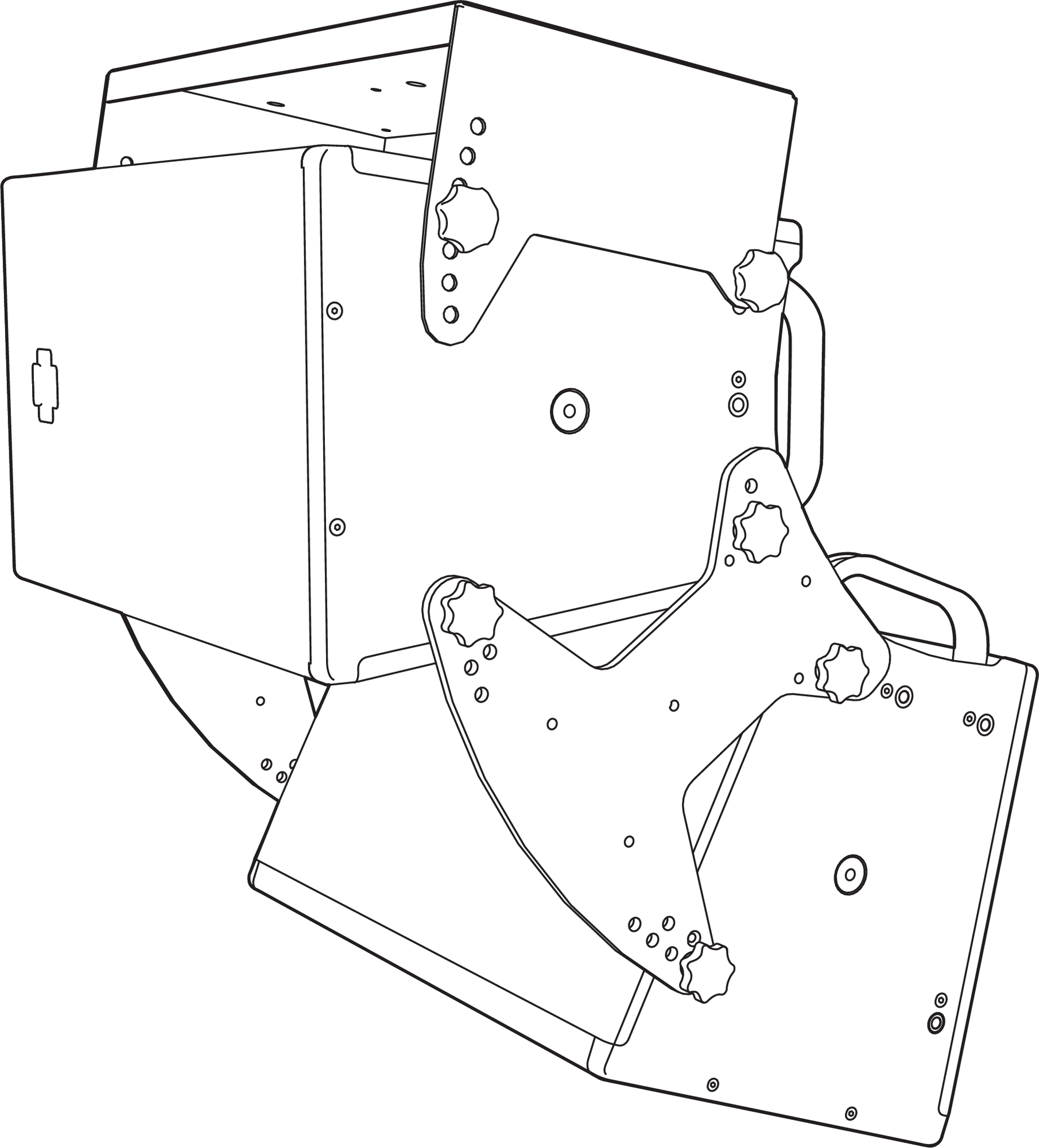
Meyer Sound offers two cluster plate versions: the MCP50-X40 Cluster Plate (PN 40.287.100.01), which when used in pairs, facilitates installation of up to three ULTRA-X40/42 loudspeakers in both horizontal and vertical clusters at variable splay angles between 10° and 50° in 5° increments, and the MCP70-X40 Cluster Plate (PN 40.287.400.01) that supports splay angles between 40° and 70°, also in 5° degree increments.
MCP70-X40 Cluster Plate (M8 knobs in transport positions)
MCP70-X40 Cluster Plate (M8 knobs in transport positions)
These kits include four M8 bolts and four M8 knobs. The bolts are recommended for fixed installations, while the knobs are for portable applications. The MCP plates include four threaded positions to hold the M8 knobs during transport.
Using these cluster plates, along with the MTC-X40 Top Channel, or the MTB-X40 Top Bracket (see MTB-X40 Top Bracket, users have the ability to create horizontal and vertical two and three-speaker clusters.
Even splay angles are obtained by using symmetric holes on either side; odd splay angles use a wider position hole on one side of the cluster plate. See Table 8 for examples.
Caution
When making horizontal clusters, always use two plates—one on top and one on bottom—to splay two adjacent loudspeakers (two plates for two-loudspeaker clusters, four plates for three-loudspeaker clusters).
Note
Optimal acoustical performance for an ULTRA-X40/42 array is achieved by using an adequate number of units as well as selecting the specific angles between cabinets to fill the requirements of the application. In general, larger angles can create a hole in the coverage and smaller angles can cause too much interaction.
Tip
The MAPP System Design Tool, covered in greater detail in Chapter 7, is the method of choice to enable you to make accurate and comprehensive predictions for optimal coverage during the design phase.
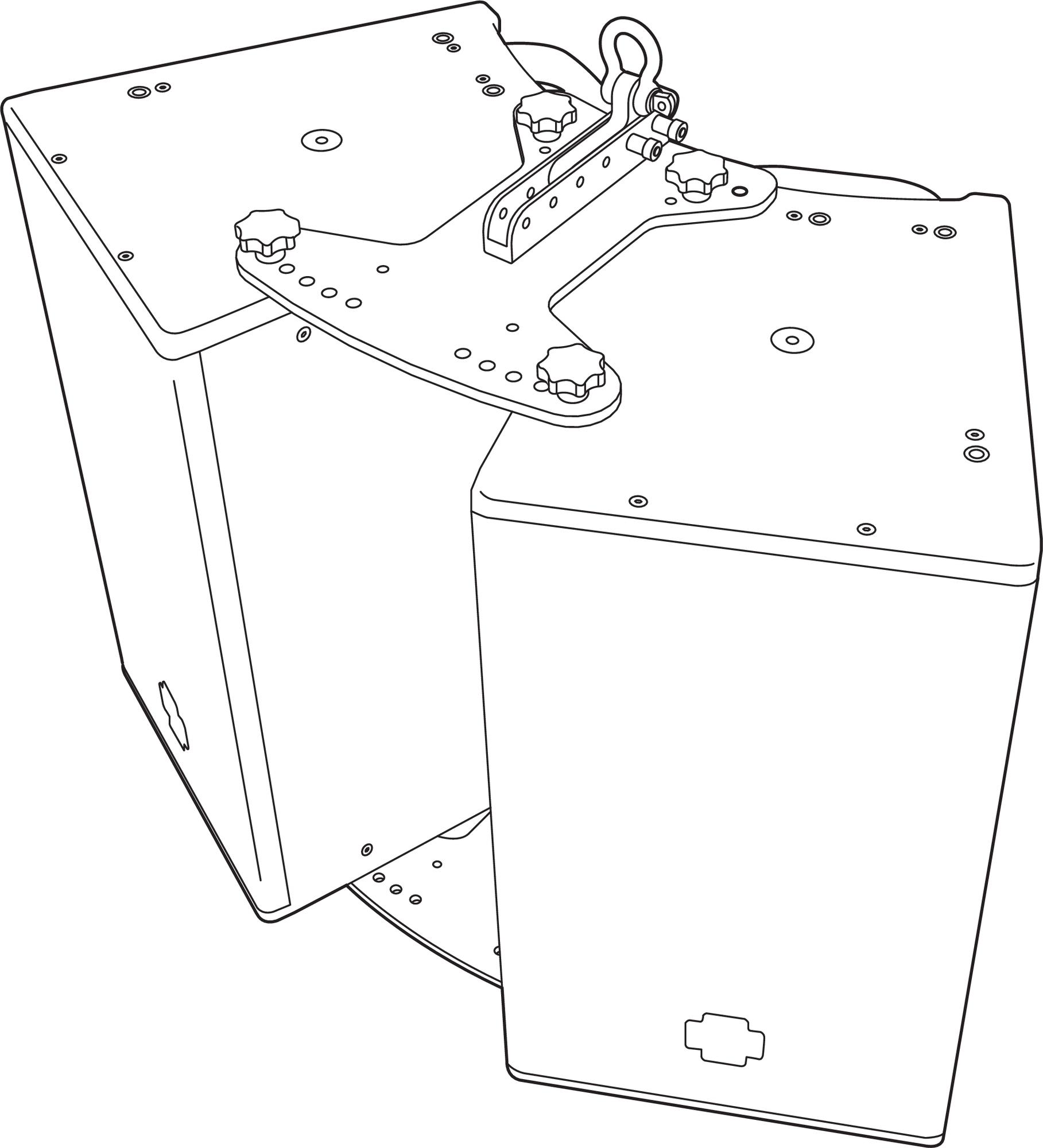
MCP50-X40 Cluster Plate shown in a 50° horizontal splay angle, two-loudspeaker cluster with MTC-X40 Top Channel on top
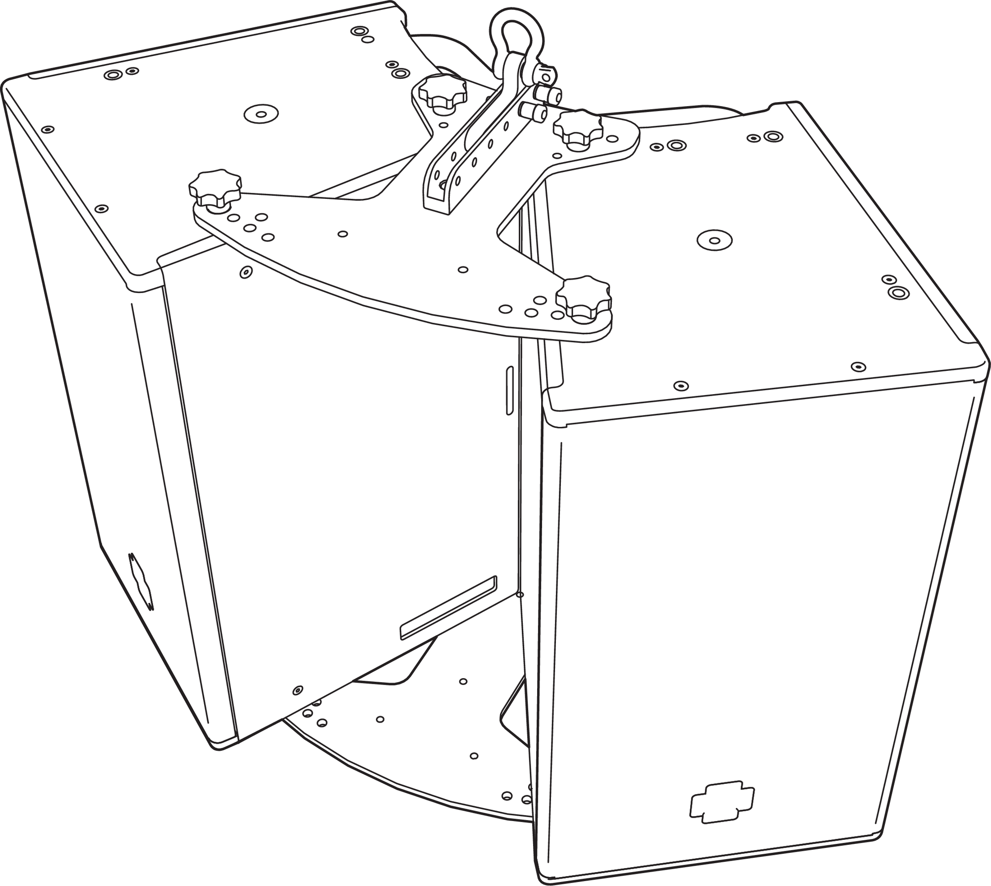
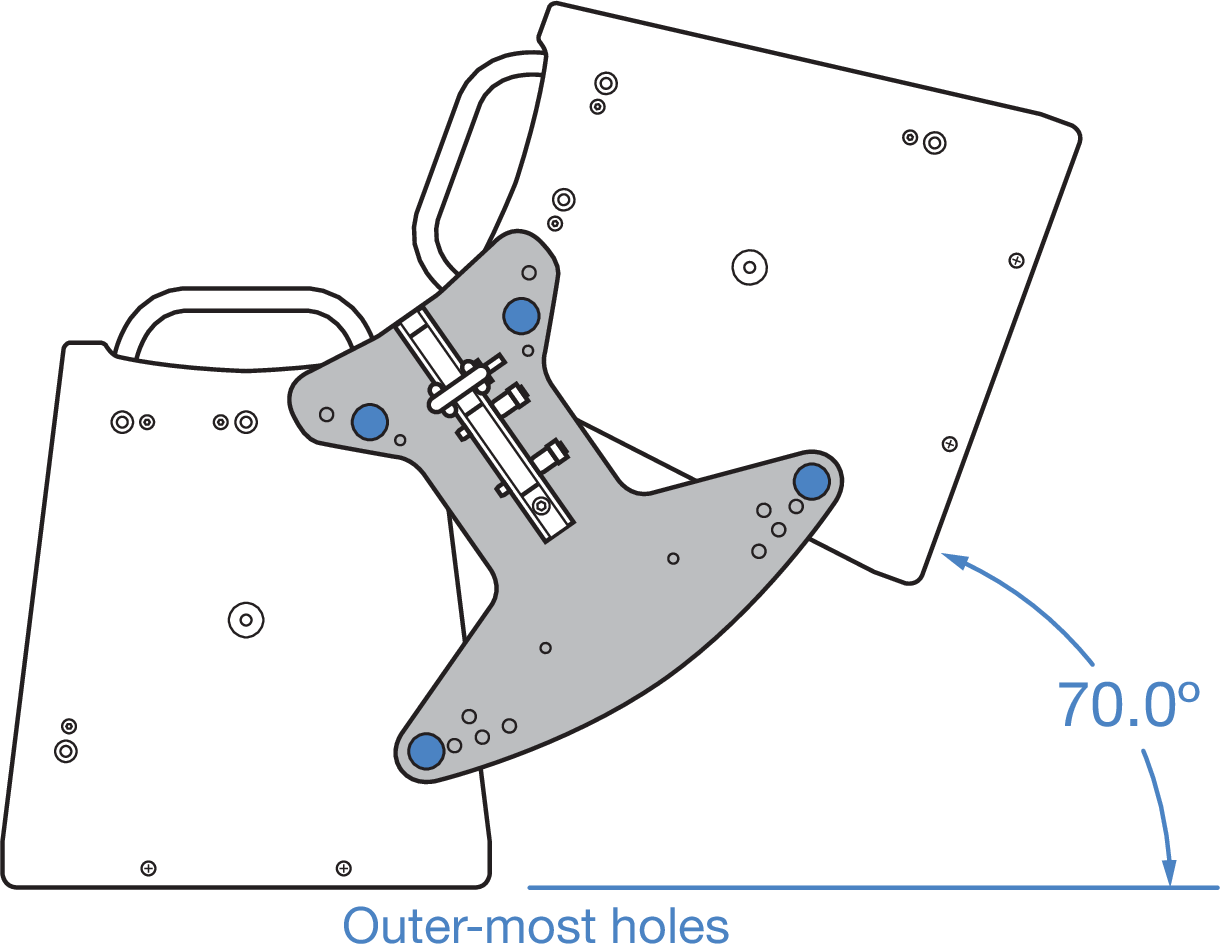
MCP70-X40 Cluster Plate shown in a 70° horizontal splay angle, two-loudspeaker cluster with MTC-X40 Top Channel on top
The table below provides illustrations of the type of splay angle configurations possible with two- and three-loudspeaker, horizontal and vertical configurations.
Tip
Use MAPP to accurately predict the interaction of loudspeakers at different angles to ensure appropriate loudspeaker deployment and subwoofer integration. For more information, see MAPP System Design Tool.
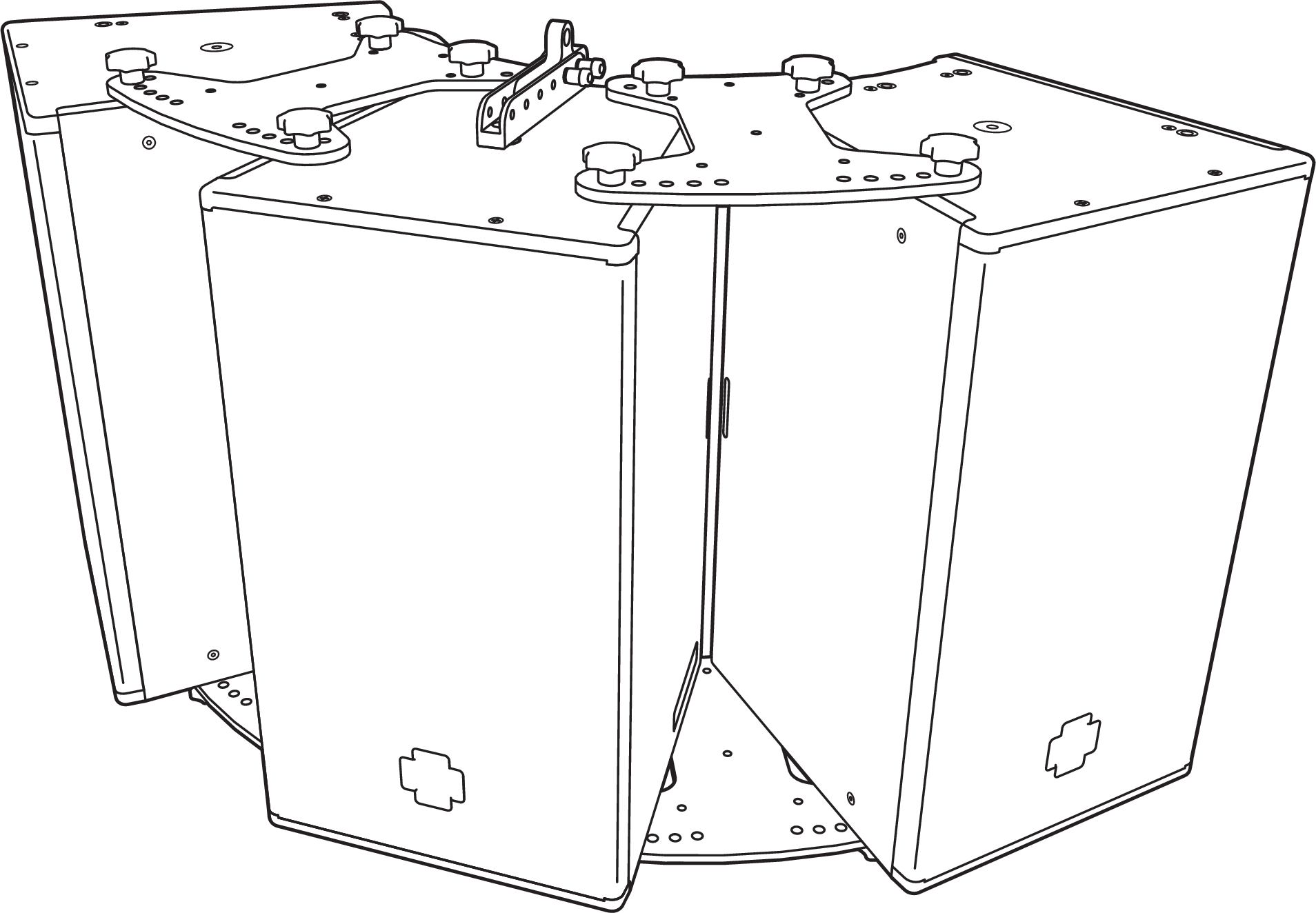
Four MCP50-x40 Cluster Plates shown set to 50° horizontal splay angles with MTC-X40 Top Channel for pick up point on center loudspeaker
MCP50-X40 Cluster Plate Examples | MCP70-X40 Cluster Plate Examples |
|---|---|
 | 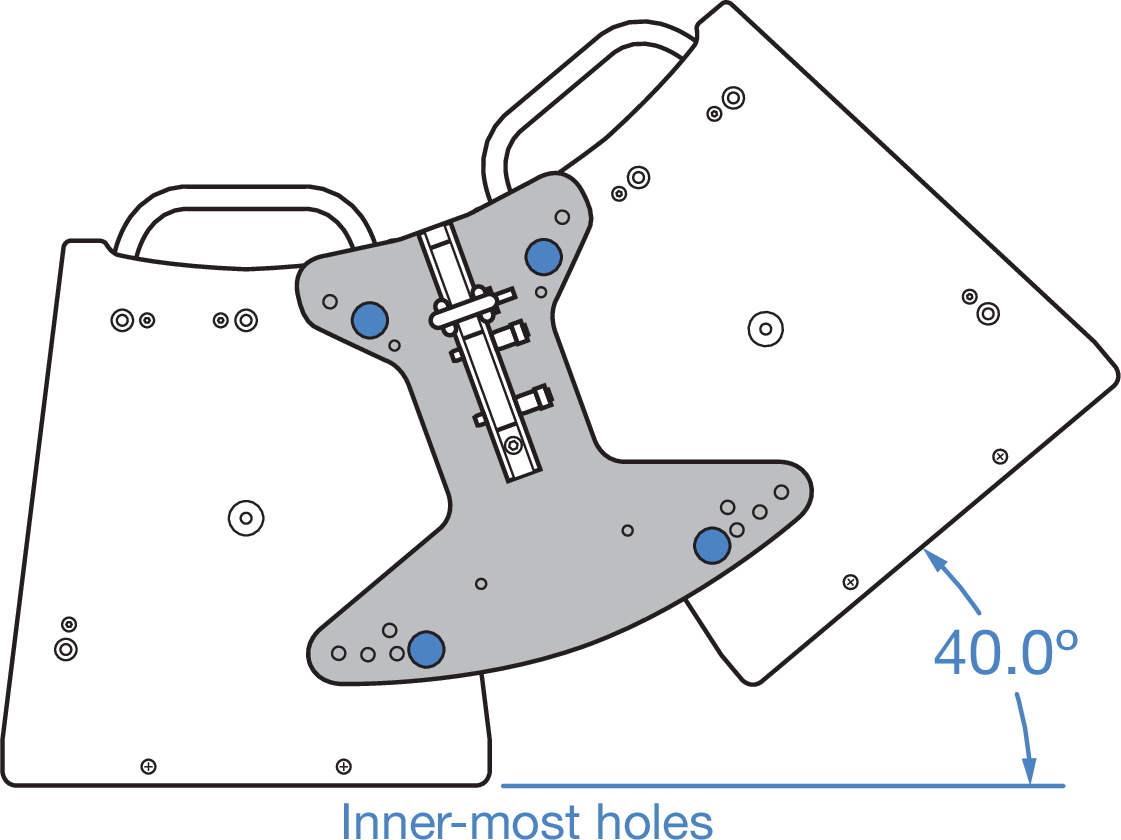 |
 |  |
 |  |
 |  |
 |  |
 |  |
MTB-X40 Top Bracket
The MTB-X40 Top Bracket (PN 40.287.150.01) is a heavy duty, U-bracket style accessory that facilitates mounting of up to three ULTRA-X40/42 loudspeakers from a ceiling or truss. The kit includes four M8 bolts, and four M8 knobs.
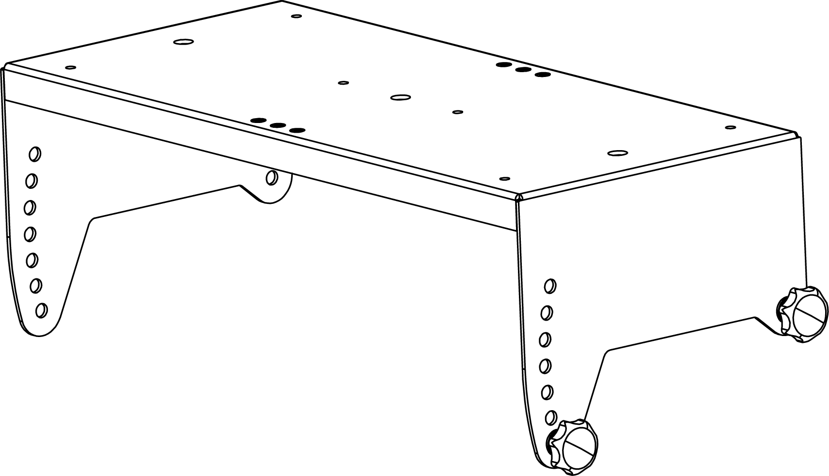
MTB-X40 Top Bracket
The bolts are recommended for fixed installations, while the knobs are for portable applications.
The design supports from 5° to 25° of downtilt in 5° increments (Figure 61). It supports 5° of uptilt (Figure 63). It also enables mounting of a single ULTRA-X40/42 onto the floor for front-fills.
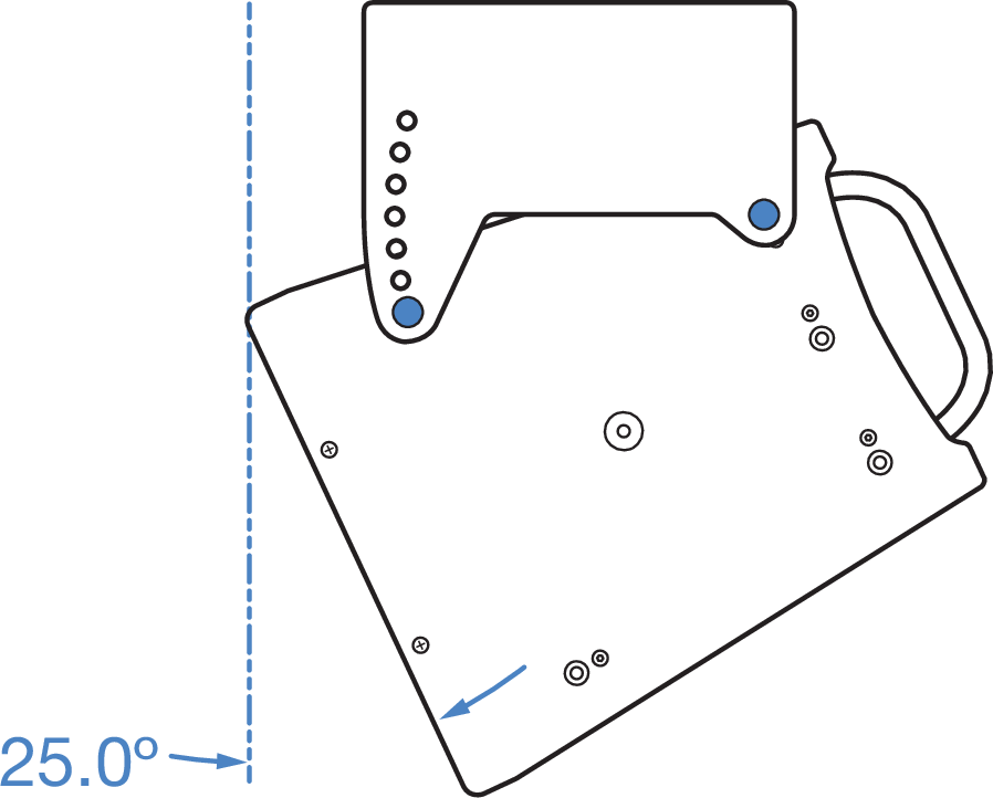
MTB-X40 Top Bracket set at 25° downtilt
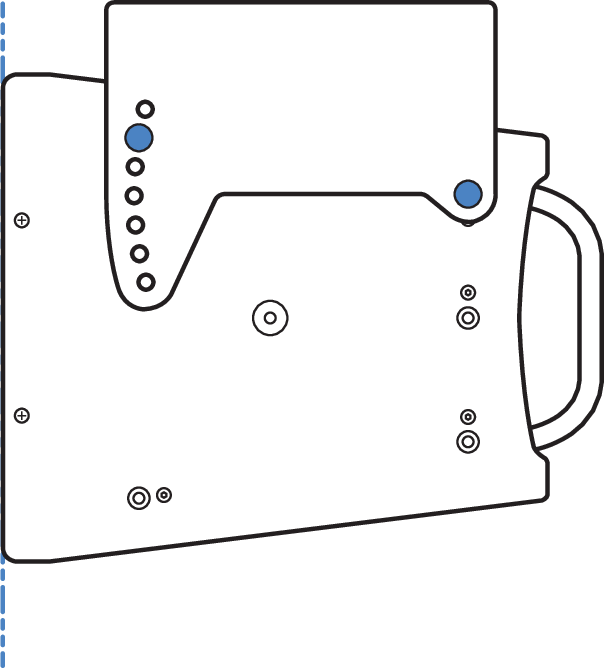
MTB-X40 Top Bracket set at 0°
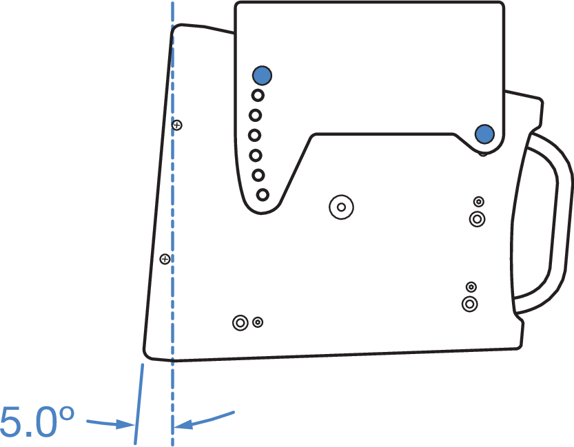
MTB-X40 Top Bracket set at 5° uptilt
The sturdy MTB-X40 Top Bracket can support up to three ULTRA-X40/42 loudspeakers in a vertical cluster (Figure 64 and Figure 65) when used in conjunction with either of the MCP50-X40 or the MCP70-X40 Cluster Plates. Two plates (one kit) are required for two-speaker clusters. Four plates (two kits) are required for three-speaker clusters.
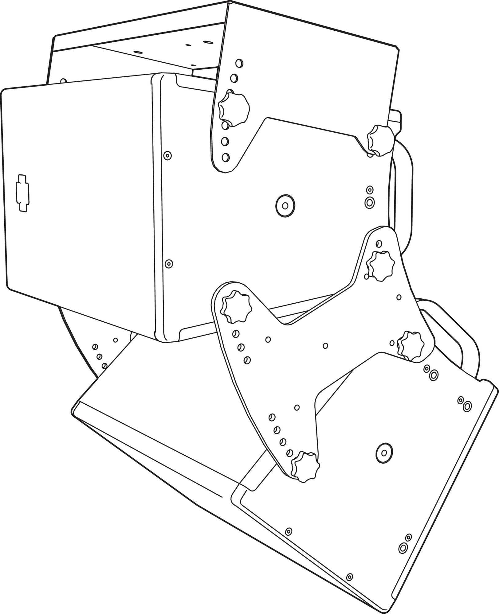
MCP50-X40 Cluster Plate creates a 50° vertical splay angle cluster with the MTB-X40 Top Bracket on top set at 10° angle
MCP70-X40 Cluster Plate creates a 70° vertical splay angle cluster with the MTB-X40 Top Bracket on top set at 10° angle
Caution
When making vertical clusters, always use two plates—one on the left and one on the right—to splay two adjacent loudspeakers (two plates for two-loudspeaker clusters, four plates for three-loudspeaker clusters).
The splay angles created by the cluster plate configurations as illustrated in Table 8 apply to vertical clusters as well. Figure 66, Figure 67 and Figure 68 provide representative drawings in the vertical orientation to illustrate.
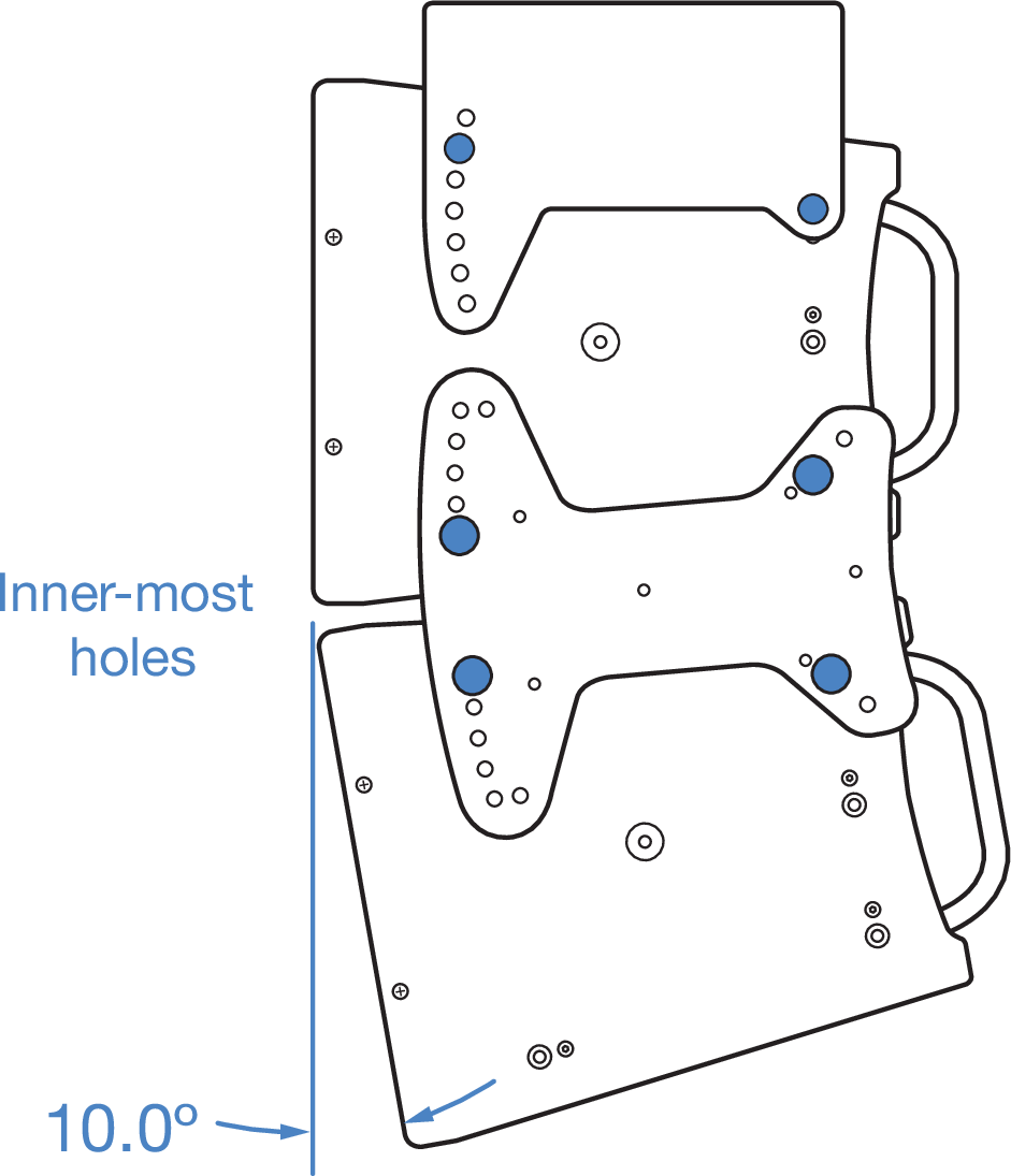
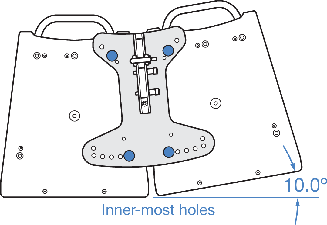
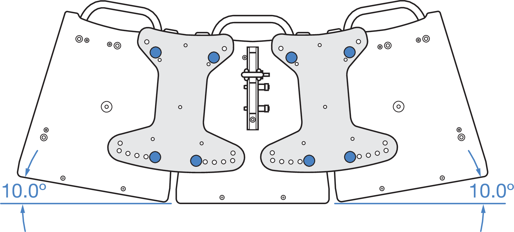
MCP50-X40 Cluster Plate in 10° vertical splay angle
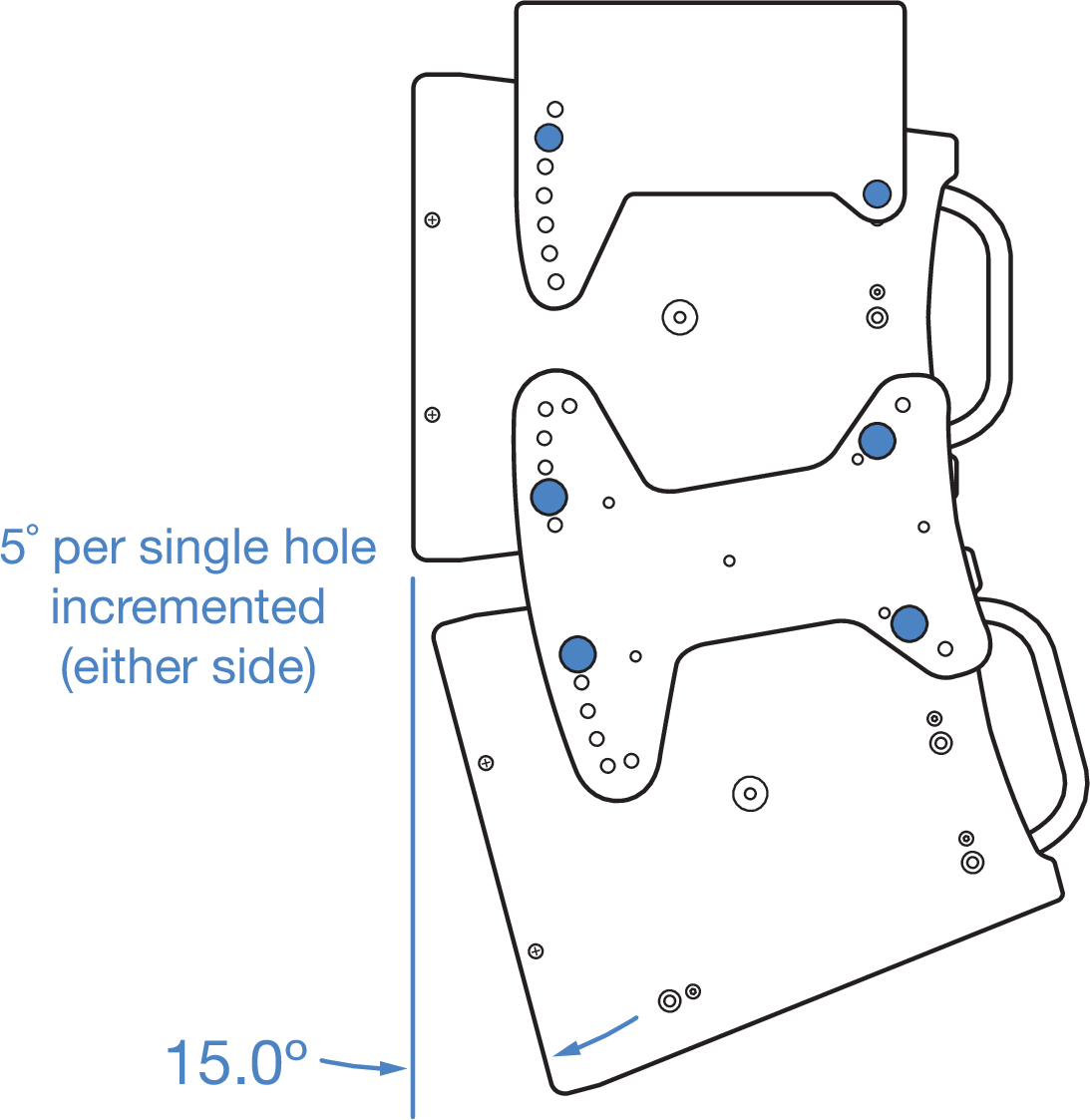
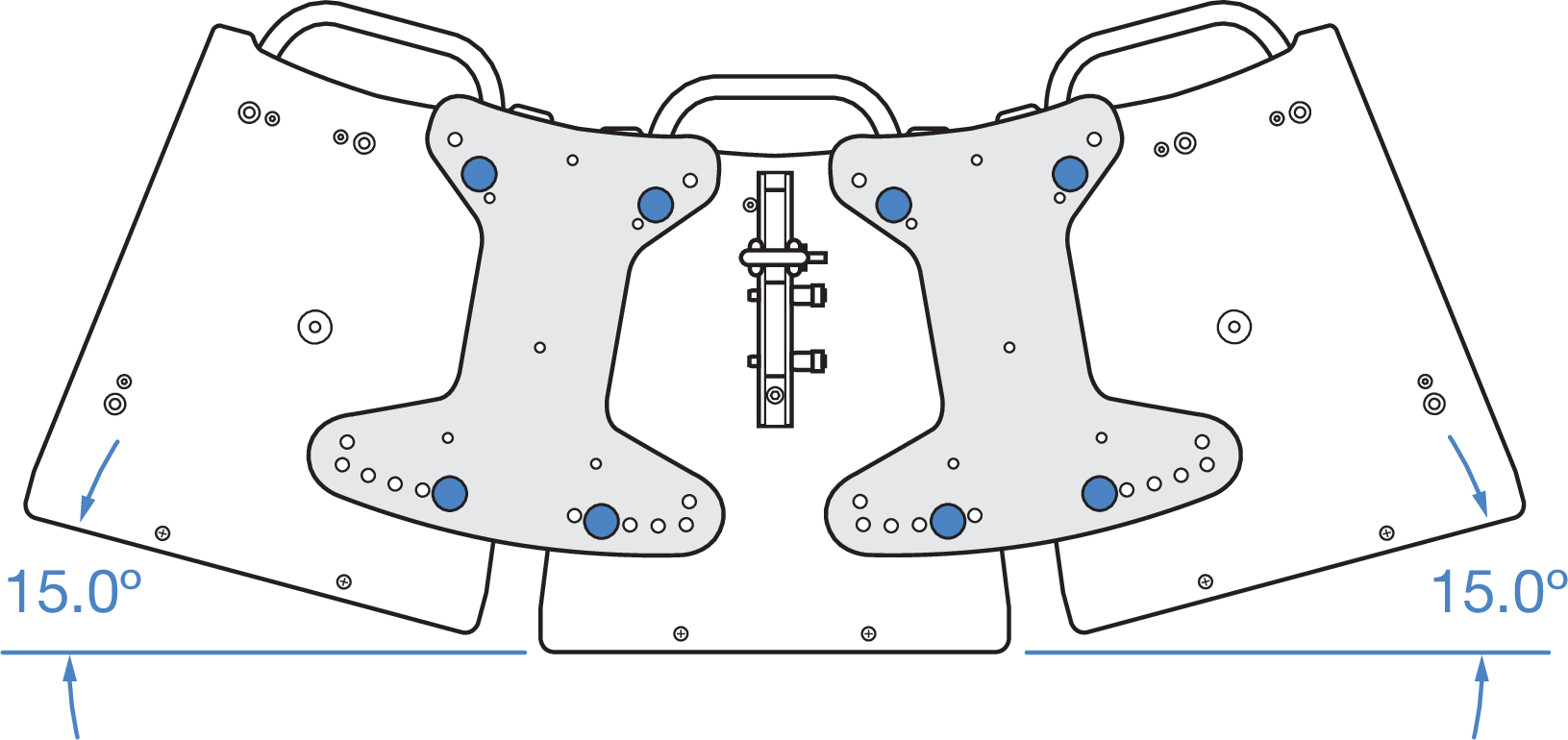
MCP50-X40 Cluster Plate in 15° vertical splay angle
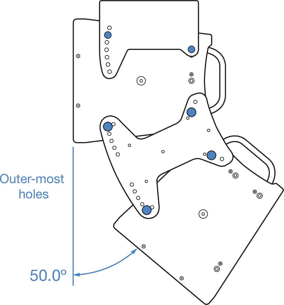
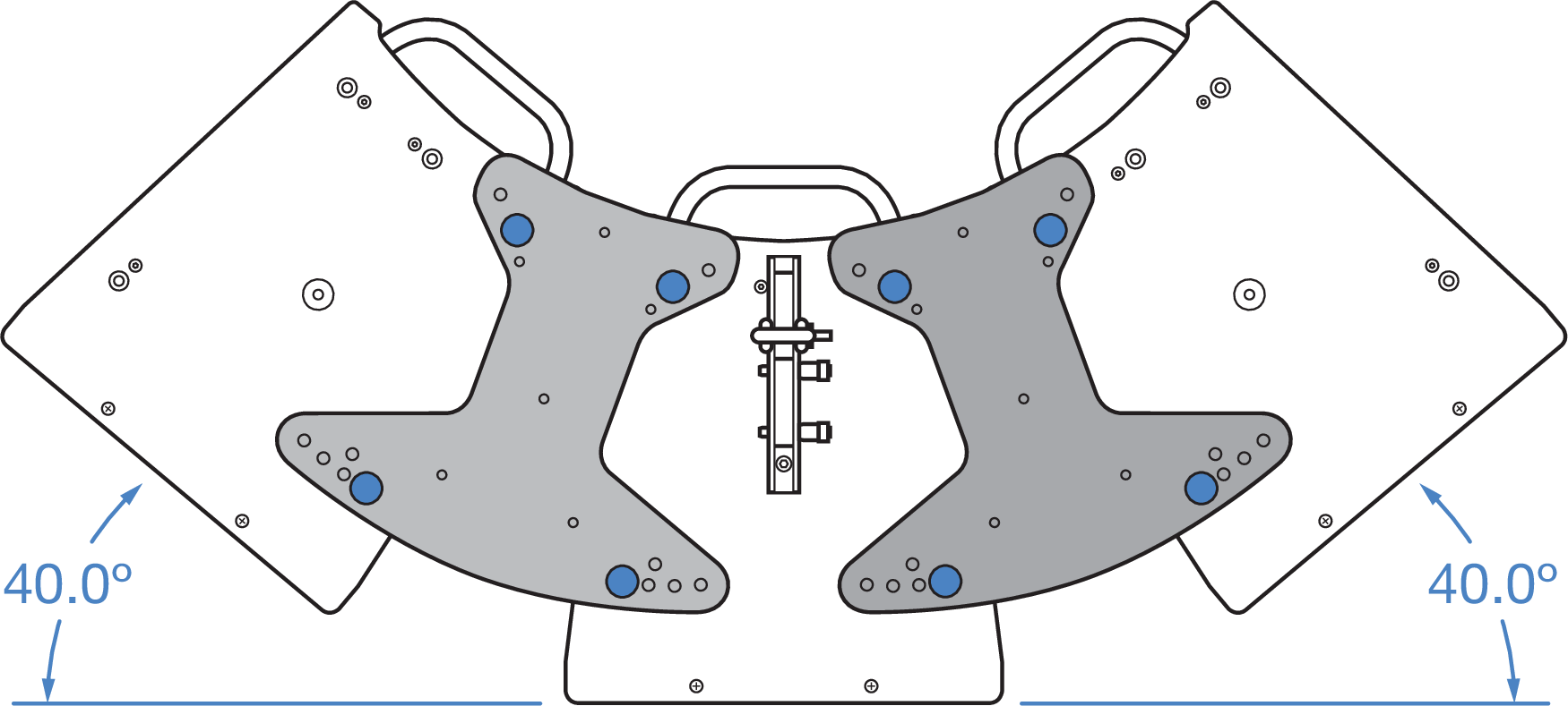
MCP50-X40 Cluster Plate in 50° vertical splay angle
Caution
When mounting the MTB-X40 from the Center hole (Figure 69), a maximum of two loudspeakers maybe clustered.
When making three-loudspeaker vertical clusters using the MTB-X40, the MTB-X40 must always be horizontal (0°) with respect to the floor.
For three-loudspeaker clusters, there are BGV-C1 limitations on the maximum angles between the MTB-X40 and the first loudspeaker, and on the angles between the first/second and second/third loudspeakers. See Figure 69, Figure 70, Table 9 and Table 10.
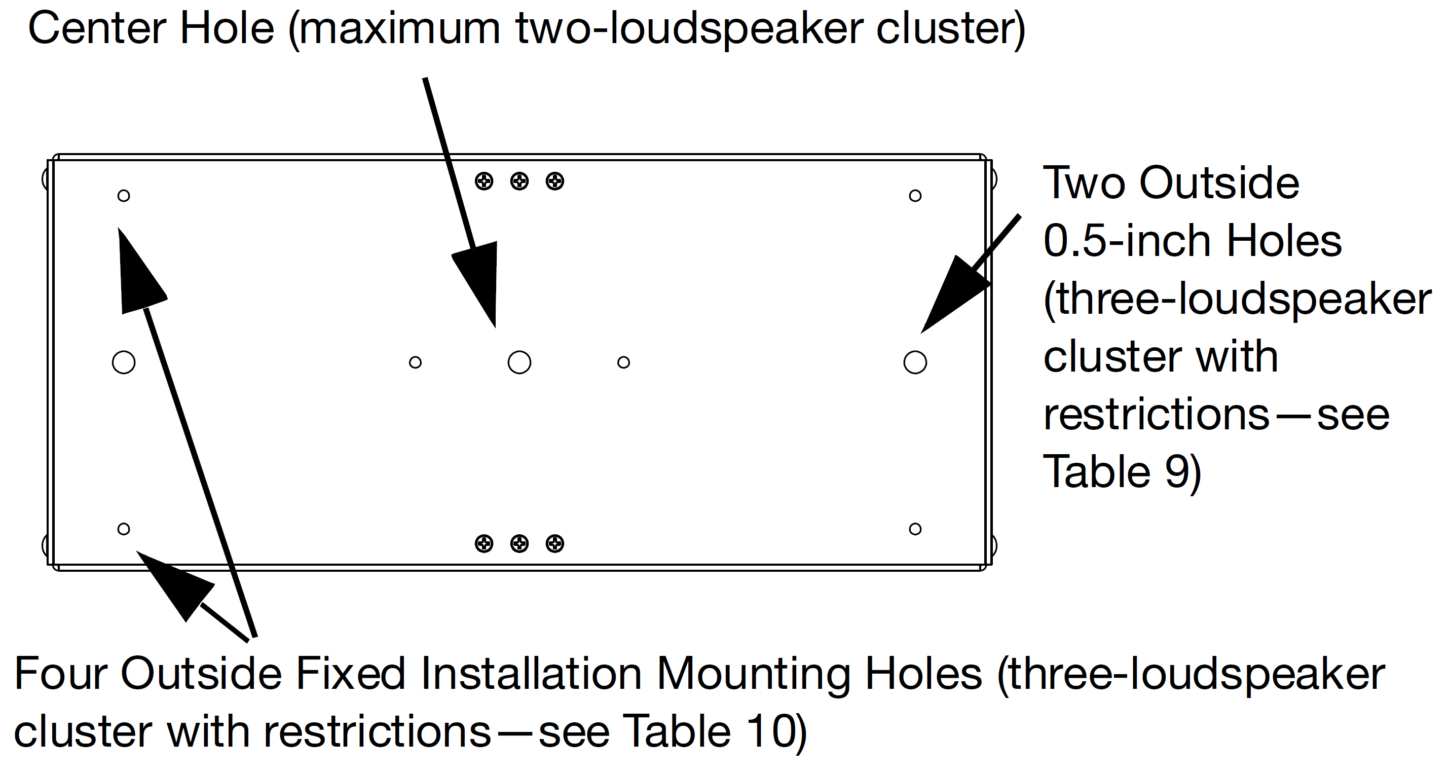
MTB-X40 (top side) mounting hole options
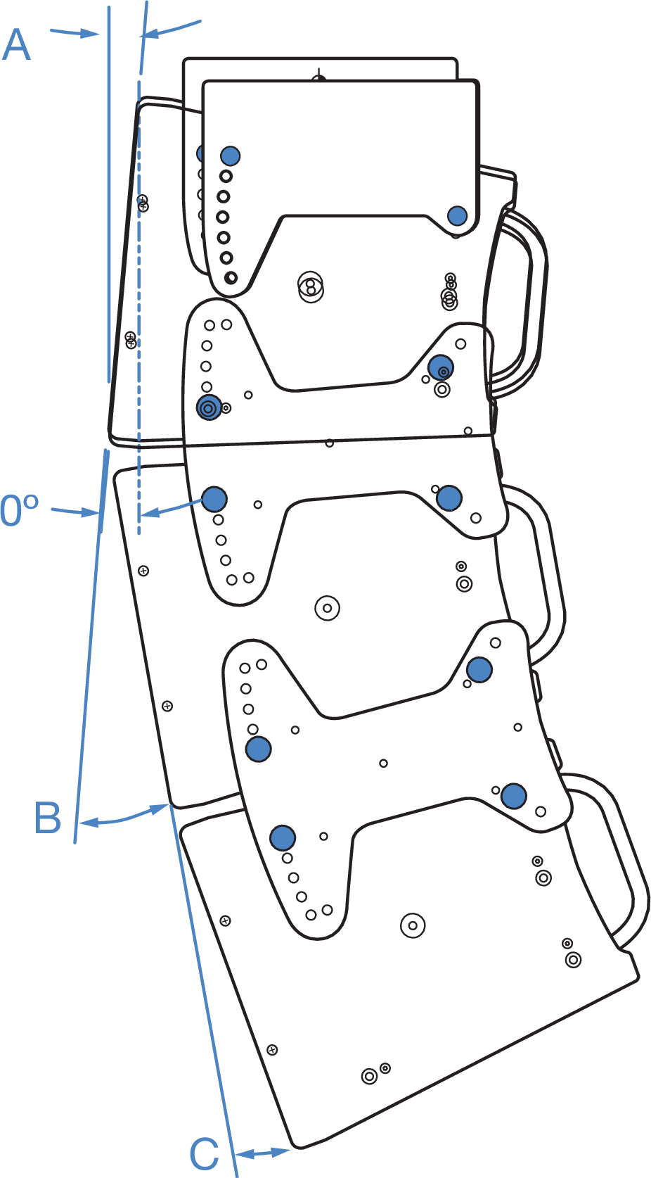
Three-ULTRA-X40 vertical cluster angles
A | B | C |
|---|---|---|
+5° | -10° to -35° | No restrictions |
-40° | -10° to -55° | |
-45° | -10° to -40° | |
-50° to -70° | 3rd loudspeaker not allowed | |
0° | -10° to -25° | No restrictions |
-30° | -10° to -60° | |
-35° | -10° to -35° | |
-40° to -70° | 3rd loudspeaker not allowed | |
-5° | -10° to -15° | No restrictions |
-20° | -10° to -60° | |
-25° | -10° to -40° | |
-30° | -10° to -30° | |
-35° to -70° | 3rd loudspeaker not allowed | |
-10° to -25° | All angles | 3rd loudspeaker not allowed |
A | B | C |
|---|---|---|
+5° | All angles | No restrictions |
0° | All angles | No restrictions |
-5° | -10° to -55° | No restrictions |
-60° | -10° to -45° | |
-65° | -10° to -35° | |
-70° | 3rd loudspeaker not allowed | |
-10° | -10° to -45° | No restrictions |
-50° | -10° to -45° | |
-55° | -10° to -35° | |
-60° to -70° | 3rd loudspeaker not allowed | |
-15° | -10° to -30° | No restrictions |
-35° | -10° to -65° | |
-40° | -10° to -45° | |
-45° | -10° to -30° | |
-50° to -70° | 3rd loudspeaker not allowed | |
-20° | -10° to -20° | No restrictions |
-25° | -10° to -65° | |
-30° | -10° to -45° | |
-35° to -70° | 3rd loudspeaker not allowed | |
-25° | All angles | 3rd loudspeaker not allowed |
Note
Optimal acoustical performance for an ULTRA-X40/42 array is achieved by using the adequate number of units as well as selecting the specific angles between cabinets to fill the require- ments of the application. In general, larger angles can create a hole in the coverage and smaller angles can cause too much interaction.
Tip
The MAPP System Design Tool, covered in greater detail in [→ _bookmark108]Chapter 7, is the method of choice to enable you to make accurate and comprehensive predictions for optimal coverage during the design phase.