Amplification and Audio
The MJF-208 and MJF-210’s low- and high-frequency drivers are powered by an extremely efficient onboard three-channel, class D amplifier that uses minimal AC power when idle. Internal signal processing includes a complex crossover, frequency and phase correction, and limiters that prevent driver over-excursion and regulate voice coil temperatures, ensuring maximum driver lifespan.
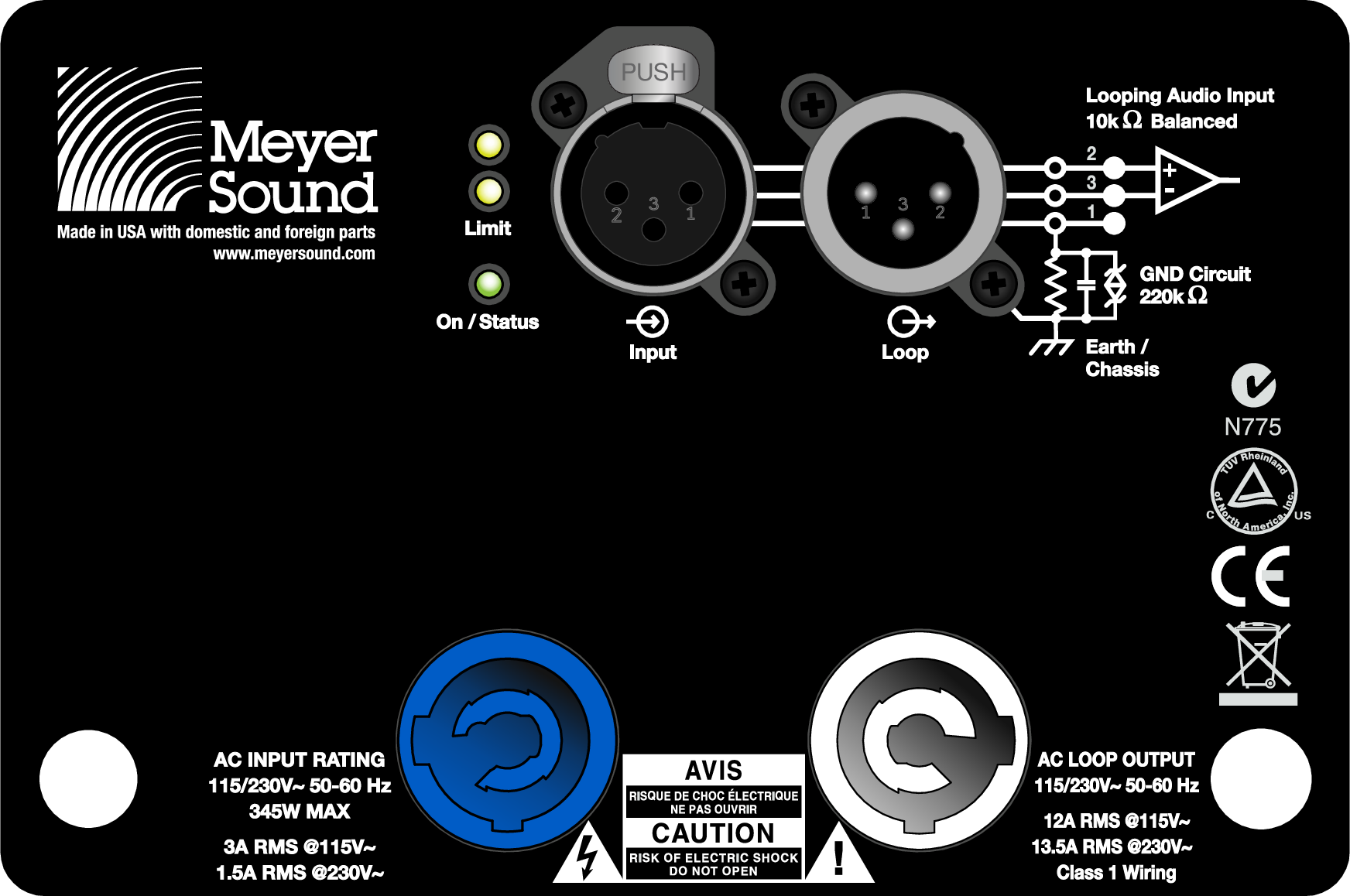 |
MJF-208/MJF-210 Rear Panel with 3-Pin XLR Connectors
The MJF-208/MJF-210 rear panel includes a slot for the optional RMS module, used for connecting to the RMS remote monitoring system (see RMS Remote Monitoring System.
Audio Connectors
The MJF-208/MJF-210 comes standard with 3-pin XLR connectors for audio Input and audio Loop output. The 5-pin XLR connectors are optionally available.
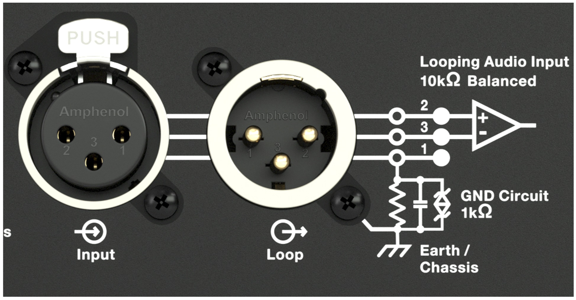 |
MJF-208/MJF-210 XLR Audio Connectors, Input and Loop Output
Input Connector (XLR 3-Pin Female)
The audio Input is an 3-pin XLR female connector and accepts balanced audio signals with an input impedance of 10 kΩ. The connector uses the following wiring:
Pin 1 — 1 kΩ to chassis and earth ground (ESD clamped)
Pin 2 — Signal (+)
Pin 3 — Signal (–)
Case — Earth (AC) ground and chassis
Pins 2 and 3 carry the input as a differential signal. Pin 1 is connected to earth through a 1 kΩ, 1000 pF, 15 V clamped network. This circuitry provides virtual ground lift for audio frequencies while allowing unwanted signals to bleed to ground. Make sure to use standard, balanced XLR audio cables with pins 1–3 connected on both ends. Telescopic grounding is not recommended, and shorting an input connector pin to the case may cause a ground loop, resulting in hum.
Tip
If unwanted noise or hiss is produced by the loudspeaker, disconnect its input cable. If the noise stops, there is most likely nothing wrong with the loudspeaker. To locate the source of the noise, check the audio cable, source audio, and AC power.
Loop Output Connector (3-Pin XLR Male)
The audio Loop output is a 3-pin XLR male connector. It allows loudspeakers to be looped from a single audio source. For applications that require multiple MJF-208/ MJF-210s, connect the Loop output of the first unit to the Input of the second, and so forth.
Note
The Loop connector is wired in parallel to the Input connector and transmits the unbuffered source signal even when the MJF-208/ MJF-210 is powered off.
To avoid distortion when looping multiple MJF-208/
MJF-210s, make sure the source device can drive the total load impedance of the looped loudspeakers. In addition, the source device must be capable of delivering approximately 20 dBV (10 V rms into 600 Ω) to yield the maximum peak SPL over the entire operating bandwidth of the loudspeakers. Most professional audio equipment can transmit these source levels.
To calculate the load impedance for the looped loudspeakers, divide 10 kΩ (the input impedance for a single MJF-208/MJF-210) by the number of looped loudspeakers. For example, the load impedance for ten MJF-208/MJF-210 loudspeakers is 1000 Ω (10 kΩ / 10). To drive this number of looped loudspeakers, the source device should have an output impedance of 100 Ω or less. This same rule applies when looping MJF-208/MJF-210 loudspeakers with other self-powered Meyer Sound loudspeakers.
Note
Most source devices are capable of driving loads no smaller than 10 times their output impedance.
Caution
Make sure that all cabling for looped loudspeakers is wired correctly (Pin 1 to Pin 1, Pin 2 to Pin 2, and so forth) to prevent the polarity from being reversed. If one or more loudspeakers in a system have reversed polarity, frequency- quency response and coverage will be significantly degraded.
Optional 5-pin XLR Audio Connectors
The MJF-208/MJF-210 is optionally available with 5-pin XLR connectors for audio Input and audio Loop output. The connectors accept balanced audio signals with an input impedance of 10 kΩ and use the following wiring:
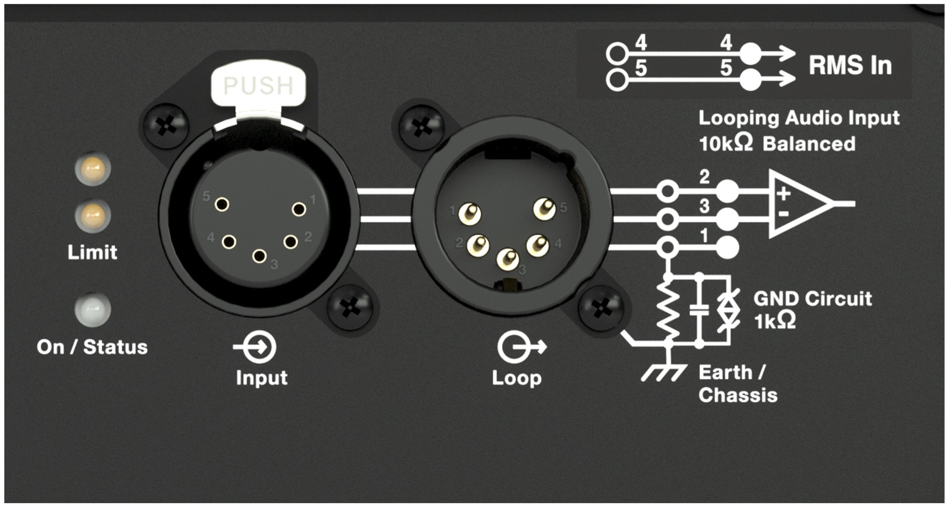 |
MJF-208/MJF-210 5-Pin XLR Connectors, Input and Loop Output
Pin 1 — 1 kΩ to chassis and earth ground (ESD clamped)
Pin 2 — Signal (+)
Pin 3 — Signal (–)
Pin 4 — RMS (polarity insensitive)
Pin 5 — RMS (polarity insensitive)
Case — Earth (AC) ground and chassis
Pins 2 and 3 carry the input as a differential signal. Pin 1 is connected to earth through a 1 kΩ, 1000 pF, 15 V clamped network. This circuitry provides virtual ground lift for audio frequencies while allowing unwanted signals to bleed to ground. Make sure to use cables that have pins 1–3 connected on both ends. Telescopic grounding is not recommended, and shorting an input connector pin to the case may cause a ground loop, resulting in hum.
Limiting
When source levels for the MJF-208/MJF-210 exceed optimum input levels for its drivers, limiting is engaged and is indicated by the two Limit LEDs on the user panel. The bottom LED indicates limiting for the low-frequency channels. The top LED indicates limiting for the high-frequency channel. When engaged, limiting not only protects the drivers, but also prevents signal peaks from causing excessive distortion in the amplifier’s channels, thereby preserving headroom and maintaining smooth frequency responses at high levels. When source levels return to normal, below the limiter’s threshold, limiting ceases.
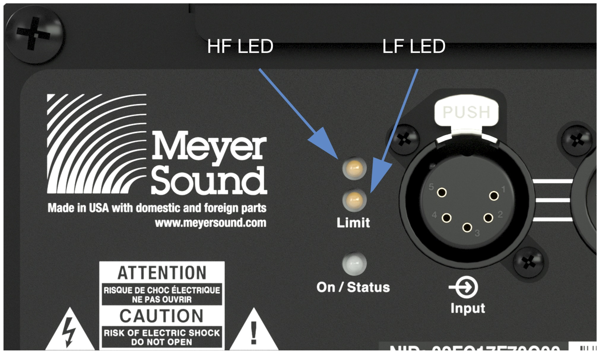 |
Limit LEDs
The MJF-208/MJF-210 performs within its acoustical specifications at normal temperatures when the Limit LEDs are unlit, or if the LEDs are lit for 2 seconds or less and then turn off for at least 1 second. If an LED remains lit for longer than 3 seconds, the loudspeaker enters hard limiting where:
Increases to the input level have no effect.
Distortion increases due to clipping and nonlinear driver operation.
Drivers are subjected to excessive heat and excursion, compromising their life span.
On/Status LED
During normal operation, the MJF-208/MJF-210’s On/Status LED is green. If the loudspeaker’s internal temperature reaches 75° C (167° F), the LED turns solid yellow and the loudspeaker’s gain is reduced by 3 dB. Although the MJF-208/MJF-210 will continue to operate normally with the lower gain, the On/Status LED illuminating yellow indicates that the loudspeaker is reaching its maximum heat dissipation and a reduction in SPL is recommended. When the loudspeaker’s internal temperature cools to 60° C (140° F), the amplifier returns to normal operation.
Caution
If the loudspeaker’s internal temperature reaches 125° C (257° F), gain is reduced by 6 dB to avoid damage to the loudspeaker.
Tip
When the MJF-208/MJF-210 is connected to an RMS network, the RMS software provides additional feedback on the loudspeaker’s operating temperature. For more information, see RMS Remote Monitoring System.
Amplifier Cooling System
The MJF-208/MJF-210 amplifier relies solely on natural convection for cooling from air flowing over its heat sink. The efficient amplifier and heat sink design keeps temperatures low, even when the unit is operated at high ambient temperatures, in tightly packed configurations, and driven continuously at high output levels.
Caution
The MJF-208/MJF-210’s heat sink can reach very high temperatures during extreme operation. Use utmost caution when approaching the rear of the loudspeaker.
The MJF-208/MJF-210 loudspeaker optionally includes an RMS remote monitoring system module, allowing them to be connected to an RMS network. RMS reports, in real-time, the status and power usage of multiple Meyer Sound loudspeakers from a Mac® or Windows®-based computer. The RMServer™ communicates with Meyer Sound loudspeakers equipped with RMS modules. RMServer is a compact, Ethernet-based hardware unit with two FT-10 RMS data ports. RMServer stores system configurations internally, eliminating most manual data entry. Systems can be monitored from a computer at front-of-house or backstage, or from a laptop anywhere within the venue over WiFi.
Note
For the latest RMS system requirements, visit meyersound.com.
RMS does not control AC power.