MM-10ACX Subwoofer
The MM-10ACX subwoofer includes onboard DC power and audio routing for driving up to two MM-4XPs. Three independent XLR female Audio In connectors are provided for the subwoofer and satellite loudspeakers. Satellite Out connectors are available as either Phoenix 5-pin male or EN3 5-pin female. The MM-10ACX also includes locking AC PowerCON connectors.
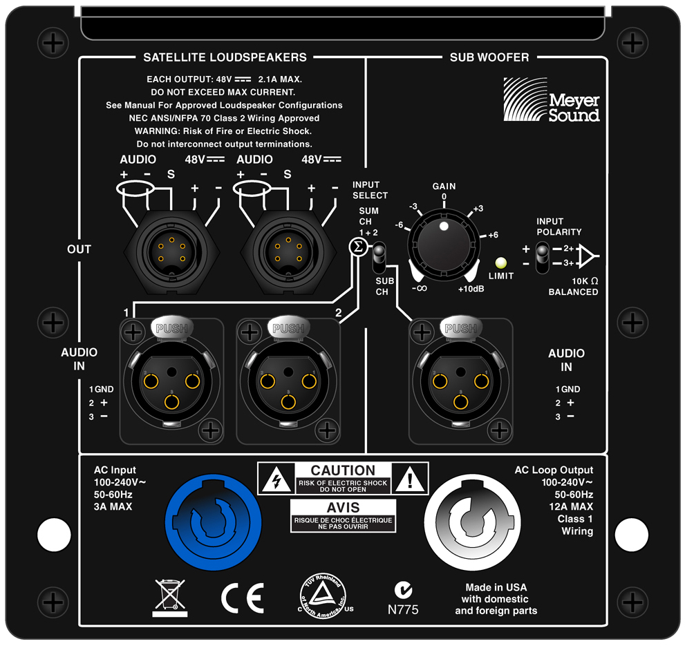 |
MM-10ACX Rear Panel, Shown with EN3 Satellite Connectors
The MM-10ACX is extremely versatile. It can be used as a standalone subwoofer or it can be connected to and used with satellite loudspeakers in several different configurations. For more information, see MM-10ACX Satellite Configurations.
MM-10ACX AC Connectors
The MM-10ACX subwoofer combines advanced loudspeaker technology with equally advanced power capabilities. Understanding voltage and current requirements, as well as electrical safety issues, is critical to the safe operation of the MM-10ACX. The MM-10ACX rear user panel includes the following PowerCON AC connectors:
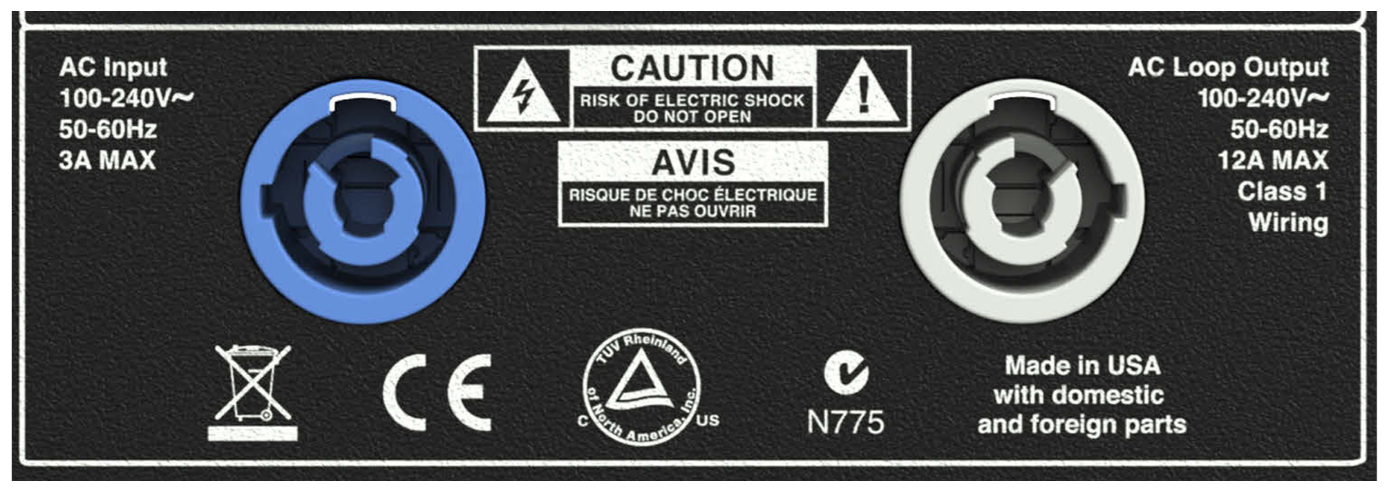 |
MM-10ACX AC Input (Left) and AC Loop Output (Right) Connectors
AC Input Connector (Blue)
The blue AC Input connector supplies power to the MM-10ACX. The input is rated at 20 amps and uses a PowerCON AC mains locking connector that prevents accidental disconnections. A 10-foot AC power cable, rated at 15 amps, is included with each MM-10ACX. If you replace the included AC power cable, make sure to use a cable with the appropriate power plug (on the other end) for the region in which you will operate the unit
The AC Input connector also supplies power to any additional subwoofers connected to the MM-10ACX’s gray AC Loop Output connector, as well as any loudspeakers connected to the Satellite Out connectors. Each MM-10ACX requires approximately 3 A rms maximum at 115 V AC and 1.5 A rms maximum at 230 V AC.
Caution
When using the included AC power cable, do not loop more than five additional MM-10ACXs from the AC Loop Output connector at 115 V (six total for the circuit), and not more than 10 at 230 V (11 total for the circuit).
AC Loop Output Connector (Gray)
The gray AC Loop Output connector allows multiple
The gray AC Loop Output connector allows multiple MM-10ACX subwoofers to be looped and powered from a single power source. Connect the AC Loop Output of the first MM-10ACX to the AC Input of the second MM-10ACX, and so forth. The AC Loop Output uses a PowerCON AC mains locking connector that prevents accidental disconnections.
The maximum number of subwoofers that can be looped from the AC Loop Output connector is determined by the voltage of the power source, the current draw of the looped subwoofers and any connected satellite loudspeakers, the circuit breaker rating, and the rating of the AC power cable connected to the MM-10ACX.
Circuit Breaker/ Connector Rating | 115 V AC | 230 V AC | 100 V AC |
|---|---|---|---|
15 amps | 5 looped (6 total) | 10 looped (11 total) | 4 looped (5 total) |
Note
The current draw for the MM-10ACX is dynamic and fluctuates as operating levels change. The numbers in Table 5 assume that operating levels are normal and not such that the subwoofers and satellite loudspeakers are constantly limiting.
Each MM-10ACX ships with one AC looping connector for making AC looping cables. Assembled AC looping cables are available from Meyer Sound.
Caution
Do not exceed the current capability of the 20-amp Input connector for the MM-10ACX. When looping MM-10ACXs, consider the total current draw for all subwoofers and satellite loudspeakers on the circuit.
Power Connector Wiring
The MM-10ACX requires a grounded outlet. To operate safely and effectively, it is extremely important that the entire system be properly grounded.
 |
AC Cable Wiring Scheme
When wiring international or special-purpose power connectors:
Connect the blue wire to the black terminal, or the terminal marked with an N.
Connect the brown wire to the red terminal, or the terminal marked with an L.
Connect the yellow and green wire to the green (or green and yellow) terminal, or the terminal marked with an E.
Caution
When creating AC power cables, it is important to preserve AC line polarity and connect the earth ground on both ends of the cable. The MM-10ACX requires a grounded connection. Always use a grounded outlet and plug. It is extremely important that the system be properly grounded to operate safely and properly. Do not ground-lift the AC cable.
MM-10ACX Voltage Requirements
The MM-10ACX operates safely and continuously when the AC voltage stays within 100–240 V AC at 50 or 60 Hz. The subwoofer allows any combination of voltage to GND (neutral-line-ground or line-line-ground).
If the voltage drops below 90 V (brownout), the MM-10ACX uses stored power to continue operating temporarily; the subwoofer will shut down if the voltage does not rise above the low boundary before the stored power is used.
If the voltage rises above 264 V, the power supply could become damaged.
Caution
The power source for the MM-10ACX should always operate within the required voltage range, at least a few volts from the upper and lower ranges. This will ensure that AC voltage variations from the service entry — or peak voltage drops due to cable runs — will not cause the subwoofer’s amplifiers to cycle on and off or cause damage to the power supply.
MM-10ACX Current Draw Requirements
The current draw for the MM-10ACX is dynamic and fluctuates as operating levels change. Since different cables and circuit breakers heat up at varying rates, it is important to understand the following types of current ratings and how they affect circuit breaker and cable specifications.
Idle Current — The maximum rms current during idle periods.
Maximum Long-Term Continuous Current — The maximum rms current during a period of at least 10 seconds. The Maximum Long-Term Continuous Current is used to calculate temperature increases for cables, to ensure that cable sizes and gauges conform to electrical code standards. The current rating is also used as a rating for slow-reacting thermal breakers. In addition, the Maximum Long-Term Continuous Current can be used to calculate the AC looping capability of the MM-10ACX.
Burst Current — The maximum rms current during a period of around one second. The Burst Current is used as a rating for magnetic breakers. It is also used for calculating the peak voltage drop in long AC cable runs according to the following formula:
V pk (drop) = I pk x R (cable total)
The Burst Current can also be used to calculate the AC looping capability of the MM-10ACX.
Ultimate Short-Term Peak Current — A rating for fast-reacting magnetic breakers.
Inrush Current — The spike of initial current encountered when powering on.
You can use the following table as a guide for selecting cable gauges and circuit breaker ratings for the system’s operating voltage.
Current Draw | 115 V AC | 230 V AC | 100 V AC |
|---|---|---|---|
Idle Current | 0.21 A rms | 0.20 A rms | 0.23 A rms |
Maximum Long-Term Continuous Current | 0.48 A rms | 0.31 A rms | 0.55 A rms |
Burst Current | 1.1 A rms | 0.6 A rms | 1.3 A rms |
Ultimate Short-Term Peak Current | 2.2 A peak | 1.6 A peak | 2.5 A peak |
Inrush Current | 6.6 A peak | 3.7 A peak | 7.2 A peak |
Current Draw | 115 V AC | 230 V AC | |
|---|---|---|---|
Idle Current | 0.32 A rms | 0.26 A rms | 0.36 A rms |
Maximum Long-Term Continuous Current | 0.90 A rms | 0.51 A rms | 1.02 A rms |
Burst Current | 2.5 A rms | 1.3 A rms | 3.0 A rms |
Ultimate Short-Term Peak Current | 4.5 A peak | 2.8 A peak | 5.0 A peak |
Inrush Current | 7.6 A peak | 4.4 A peak | 8.4 A peak |

The minimum electrical service amperage required by an MM-10ACX subwoofer system is the sum of the Maximum Long-Term Continuous Current for each unit. An additional 30 percent above the minimum amperage is recommended to prevent peak voltage drops at the service entry
Note
For the best performance, the AC cable voltage drop should not exceed 10 V, or 10 percent at 115 V and 5 percent at 230 V. Make sure that even with AC voltage drops that the AC voltage always remains within the operating window.
Electrical Safety Issues
Pay close attention to these important electrical and safety issues.
The MM-10AC requires a grounded outlet. Always use a grounded outlet and plug.

Do not use a ground-lifting adapter or cut the AC cable ground pin.

Do not exceed the current capability of the 20-amp AC Input connector for the MM-10AC. When looping MM-10ACs, consider the total current draw for all units on the circuit, including the first.
Make sure the AC power cable for the MM-10AC has the appropriate power plug (on the other end) for the area in which you will operate the unit. In addition, the AC power cable must be rated for the total current draw of all MM-10ACs looped from the power source.
Do not operate the unit if the power cable is frayed or broken.
Keep all liquids away from the MM-10AC to avoid hazards from electrical shock.
MM-10ACX Audio In Connectors
The MM-10ACX includes an XLR female Audio In connector and XLR male Audio Loop Out connector.
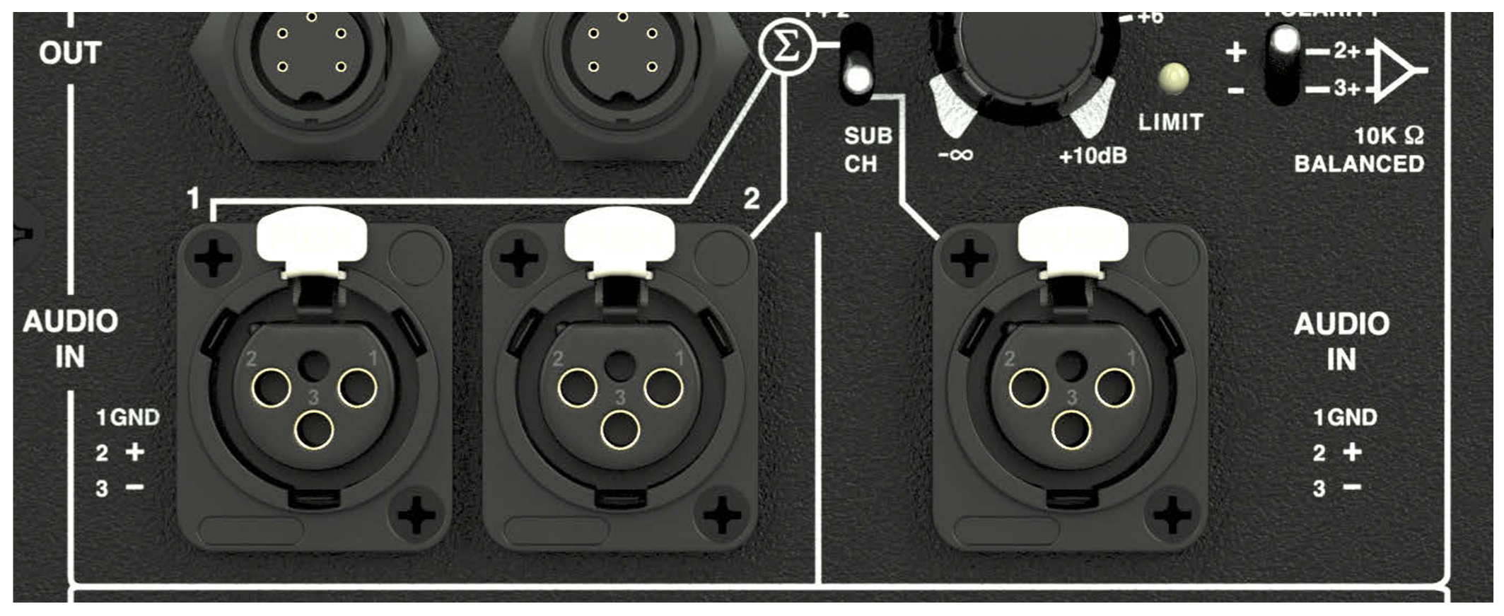 |
MM-10ACX Audio In Connectors: Satellite 1, Satellite 2, and Subwoofer
The XLR female Audio In connectors accept balanced audio signals with an input impedance of 10 kOhm. The connectors use the following wiring:
Pin 1 — 220 kOhm to chassis and earth ground (ESD clamped)
Pin 2 — Signal (+)
Pin 3 — Signal (–)
Case — Earth (AC) ground and chassis
Pins 2 and 3 carry the input as a differential signal. Pin 1 is connected to earth through a 220 kOhm, 1000 pF, 15 V clamped network. This circuitry provides virtual ground lift for audio frequencies while allowing unwanted signals to bleed to ground. Make sure to use standard, balanced XLR audio cables with all three pins connected on both ends. Telescopic grounding is not recommended, and shorting an input connector pin to the case may cause a ground loop, resulting in hum.
Tip
If unwanted noise or hiss is produced by the subwoofer, disconnect its input cable. If the noise stops, there is most likely nothing wrong with the subwoofer. To locate the source of the noise, check the audio cable, source audio, and AC power.
MM-10ACX Satellite Out Connectors
The Satellite Out connectors deliver DC power (48 V DC) and balanced audio to up to two MM-4XPs. The source audio for the satellite loudspeakers is received from the MM-10ACX’s Audio 1 In and Audio 2 In connectors. The DC power for the satellite loudspeakers is generated by the MM-10ACX’s onboard DC power capabilities.
The Satellite Outs can be equipped with either Phoenix 5-pin male connectors or EN3 5-pin female connectors.
Caution
When wiring cable connections for the Satellite Outs, it is extremely important that each pin in the connector is wired correctly. Make sure the 48 V DC from the MM-10ACX is wired directly (and only) to the 48 V DC pins on the connector for the satellite loudspeaker, and that the polarity is observed (negative to negative, positive to positive) to avoid damage to the loudspeaker. In addition, make sure the audio pins are wired correctly; polarity reversals for audio signals can affect system performance.
Phoenix Outputs
The MM-10ACX Satellite Outs are available as Phoenix 5-pin male connectors with three pins for balanced audio (positive, negative, and shield) and two pins for DC Power (positive and negative). These pins are clearly labeled on the MM-10ACX rear panel. A single composite cable (such as Belden 1502) wired for both DC power and balanced audio can be used to connect to each satellite loudspeaker.
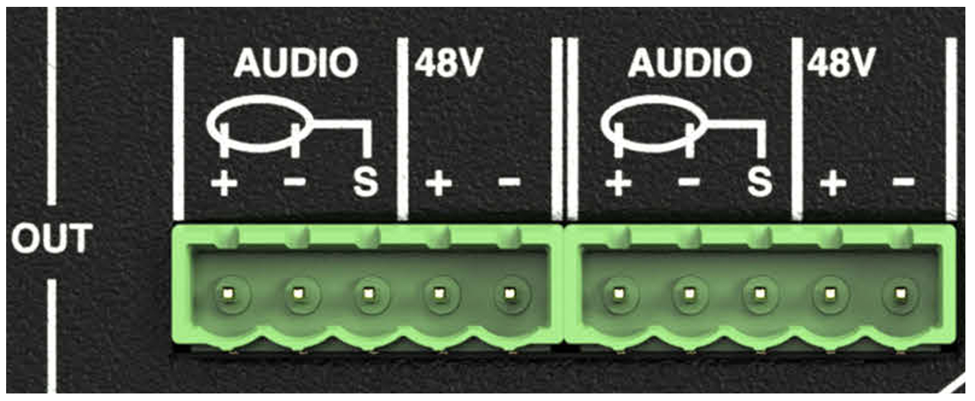 |
MM-10ACX Satellite Outs, Phoenix
When equipped with Phoenix Satellite Outs, the MM-10ACX comes with Phoenix 5-pin female cable connectors for assembling loudspeaker cables. For information on cable requirements for a satellite loudspeaker, refer to its operating instructions.
EN3 Outputs
The MM-10ACX Satellite Outs are available as EN3 5-pin female connectors with three pins for balanced audio (positive, negative, and shield) and two pins for DC Power (positive and negative). These pins are clearly labeled on the MM-10ACX rear panel. A single composite cable (such as Belden 1502) wired for both DC power and balanced audio can be used to connect to each satellite loudspeaker.
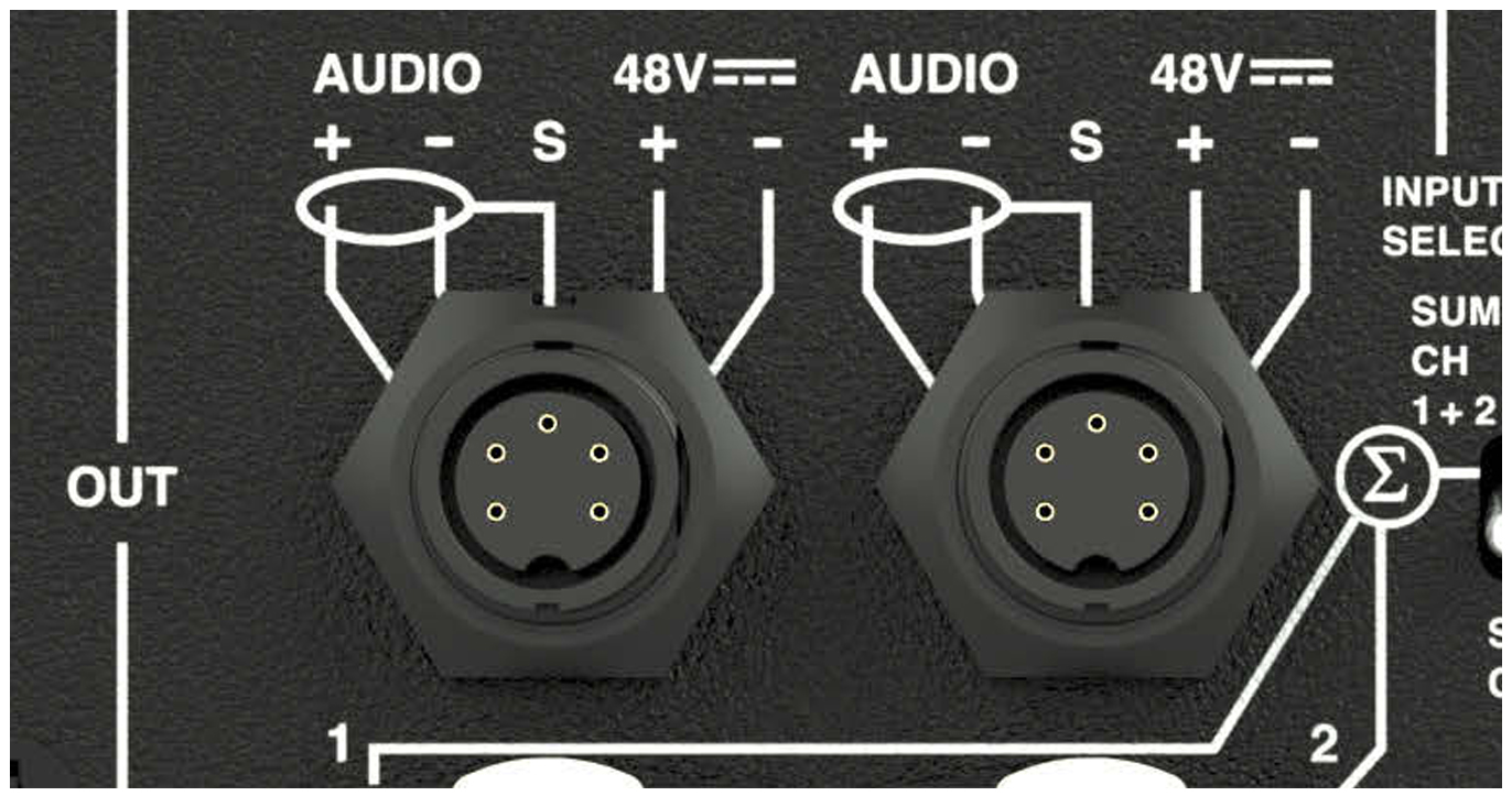 |
MM-10ACX Satellite Outs, EN3
When equipped with EN3 Satellite Outs, the MM-10ACX comes with EN3 5-pin male cable connectors for assembling loudspeaker cables. For information on cable requirements for a satellite loudspeaker, refer to its operating instructions.
Note
For information on cables and cable accessories available from Meyer Sound, see MM-10 Accessories. For information on cable assembly, see Assembling Loudspeaker Cables
M-10ACX Input Select Switch
The Input Select switch determines the audio source signal for the subwoofer. When the switch is in the down position (SUB CH), the source signal is received from the Subwoofer Audio In connector. When the switch is in the up position (SUM CH 1 + 2), the source signal is received from the Satellite 1 and Satellite 2 Audio In connectors and is summed.
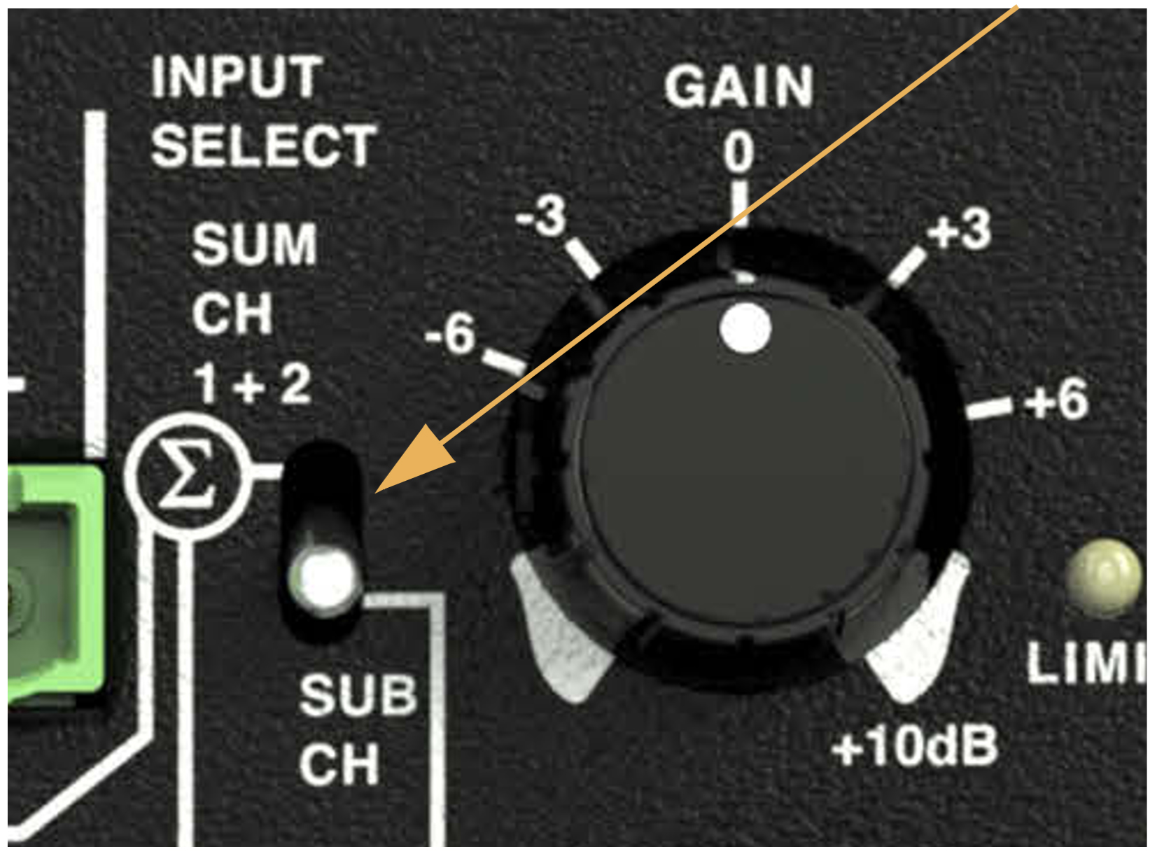 |
MM-10ACX Input Select Switch
Note
The Input Select switch is only included on the MM-10ACX model. The switch only affects the subwoofer signal and has no effect on the Satellite Outs.
Input Select Switch and Summing
When the Input Select switch is in the up position (SUM CH 1 + 2), the source signal that is routed to the subwoofer from the Satellite Audio Ins is attenuated.
If audio signals are present at both Satellite Audio Ins, the signal is summed and attenuated by 6 dB, resulting in a net gain of 0 dB.
If only a single audio signal is present at one of the Satellite Audio Ins, the signal is also attenuated by 6 dB. But this time the result is a net gain of -6 dB.
MM-10ACX Gain Knob
The Gain knob adjust the subwoofer signal from completely attenuated to +10 dB and can be used to the balanced the subwoofer output with that of the satellite loudspeakers.
The Gain knob is always active, regardless of the Input Select switch setting.
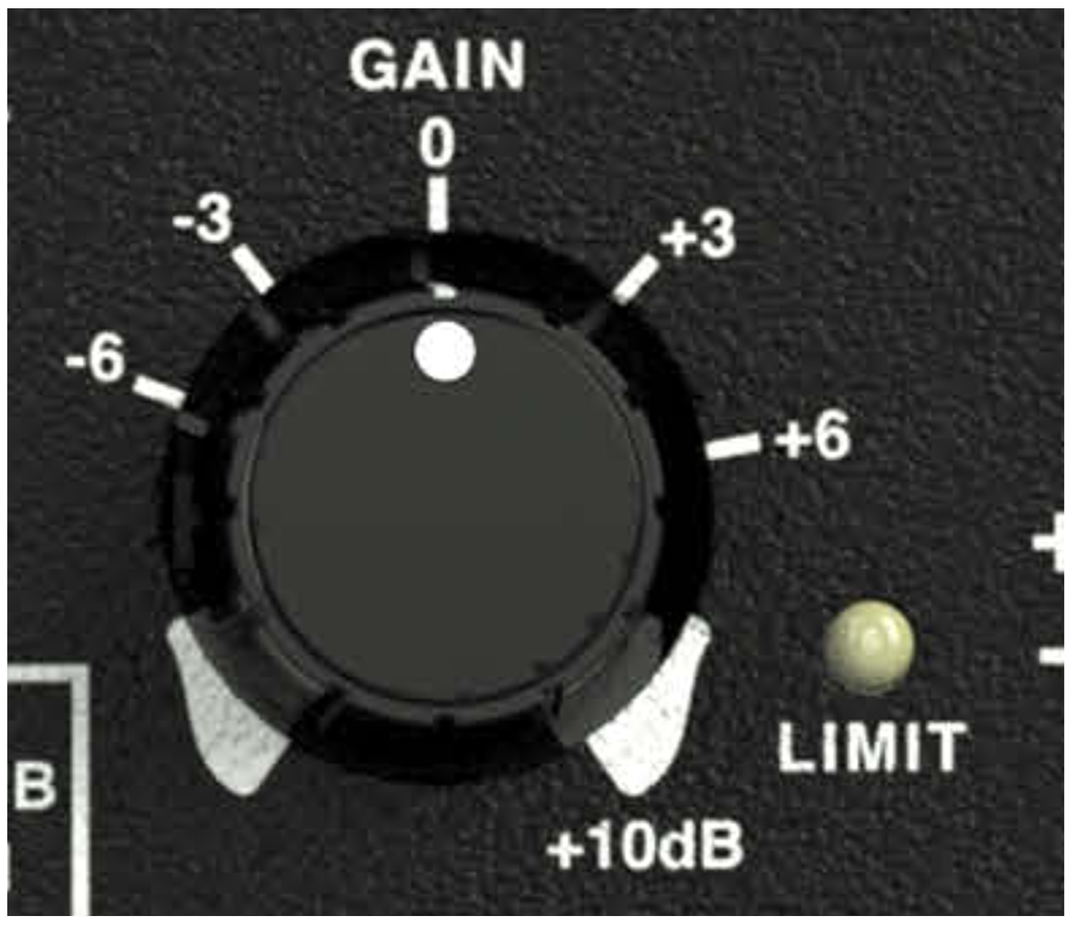 |
MM-10ACX Gain Knob
Note
The Gain knob is only included on the MM-10ACX model. The knob only affects the subwoofer signal and has no effect on the Satellite Outs.
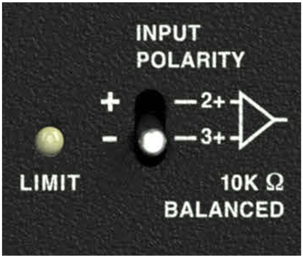
MM-10ACX Input Polarity Switch
The Input Polarity switch swaps the polarity of the audio source signal, which is sometimes necessary to acoustically align the subwoofer with other loudspeakers in the system. When the switch is in the up (+) position, pin 2 is hot relative to pin 3, resulting in a positive pressure wave when a positive signal is applied to pin 2. When the switch is in the down (–) position, pin 3 is hot relative to pin 2, resulting in a positive pressure wave when a positive signal is applied to pin 3.
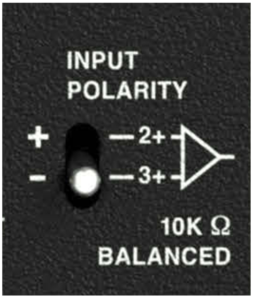 |
MM-10ACX Input Polarity Switch
Note
The Input Polarity switch only affects the subwoofer signal. It has no effect on the Satellite Outs.
MM-10ACX Limit LED
The MM-10ACX has a three-color Limit LED on its rear panel that changes color to indicate the subwoofer’s status.
 |
MM-10ACX Limit LED
USM-1P — Extended Range Narrow Coverage Stage Monitor
When powering up the MM-10XP subwoofer, the following startup events occur and are indicated by the Limit LED:
The LED flashes green and then yellow during power-up.
The LED turns solid green indicating the subwoofer is ready to reproduce audio.
Caution
If the Limit LED turns red and stays solid red after powering up and the audio is muted, the subwoofer has encountered a failure and may need to be serviced. Contact Meyer Sound Technical Support.
If the Limit LED turns solid red and the MM-10ACX continues to output audio, though at reduced levels, the subwoofer’s voltage may have dropped below 90 V AC. When these conditions are encountered, operation of the subwoofer should cease and its power supply and cabling should be verified.
Limiting (Yellow)
Limiting activity is indicated when the Limit LED turns yellow. When engaged, the limiter protects the subwoofer’s driver and prevents signal peaks from causing excessive distortion in the subwoofer’s amplifier, thereby preserving headroom and maintaining smooth frequency responses at high levels. When the level returns to normal, below the limiter’s threshold, the LED turns green and limiting ceases.
The MM-10ACX performs within its acoustical specifications at normal temperatures when the Limit LED is green, or if the LED turns yellow for two seconds or less and then returns to green for at least one second. If the LED remains yellow for longer than three seconds, the subwoofer enters hard limiting where:
Increases to the input level have no effect.
Distortion increases due to clipping and nonlinear driver operation.
The drivers are subjected to excessive heat and excursion, which will compromise their life span and may eventually lead to damage over time.
Caution
The Limit LED turns yellow when the subwoofer’s signal rises 2 dB above the limiting threshold, and indicates a safe, optimum level has been exceeded. If the MM-10ACX subwoofers in a system begin to limit before reaching the desired SPL, consider adding more subwoofers to the system to achieve the desired SPL without exposing the subwoofers to excessive levels and possible overheating.
MM-10ACX Temperature and Limiting
The Limit LED turns solid yellow when its heat sink temperature reaches 65° C (145° F), indicating the unit is reaching its maximum heat dissipation and a reduction in SPL is recommended. While the MM-10ACX will continue to operate while the LED is yellow, the limiter threshold is lowered to a safe level (causing the output level to be lowered by 6 dB) to prevent the subwoofer from overheating. When the temperature of the heat sink cools to 50°C (122°F), the LED changes from yellow to green and the limiter threshold returns to normal.
Clipping (Red)
The Limit LED flashes red when its input signal causes the amplifier to overload. If the LED flashes red continuously, the subwoofer is severely overloaded and a reduction in the input level is recommended.
Caution
If the Limit LED turns solid red and the subwoofer continues to output audio, though at reduced levels, the subwoofer’s voltage may have dropped below 90 V AC. When these conditions are encountered, operation of the subwoofer should cease and its power supply and cabling should be verified.