GALAXY enclosures and I/O
All three GALAXY processors offer the same processing on inputs and outputs but differ in their size and physical connections. The GALAXY 816-AES3 processor also includes a BNC connector for external word clock input.
GALAXY processor enclosures
The three GALAXY processors are designed to be mounted in 19-inch wide racks. The GALAXY 408 processor is 1RU in height, and the GALAXY 816 processor and the GALAXY-816-AES processor are 2RU in height. The enclosures are made from steel with a slightly textured graphite gray finish.
GALAXY processor front panels
The GALAXY 816/816-AES and GALAXY 408 processor front panels, shown in the figure below, provide basic information and mute control of the loudspeaker management system.
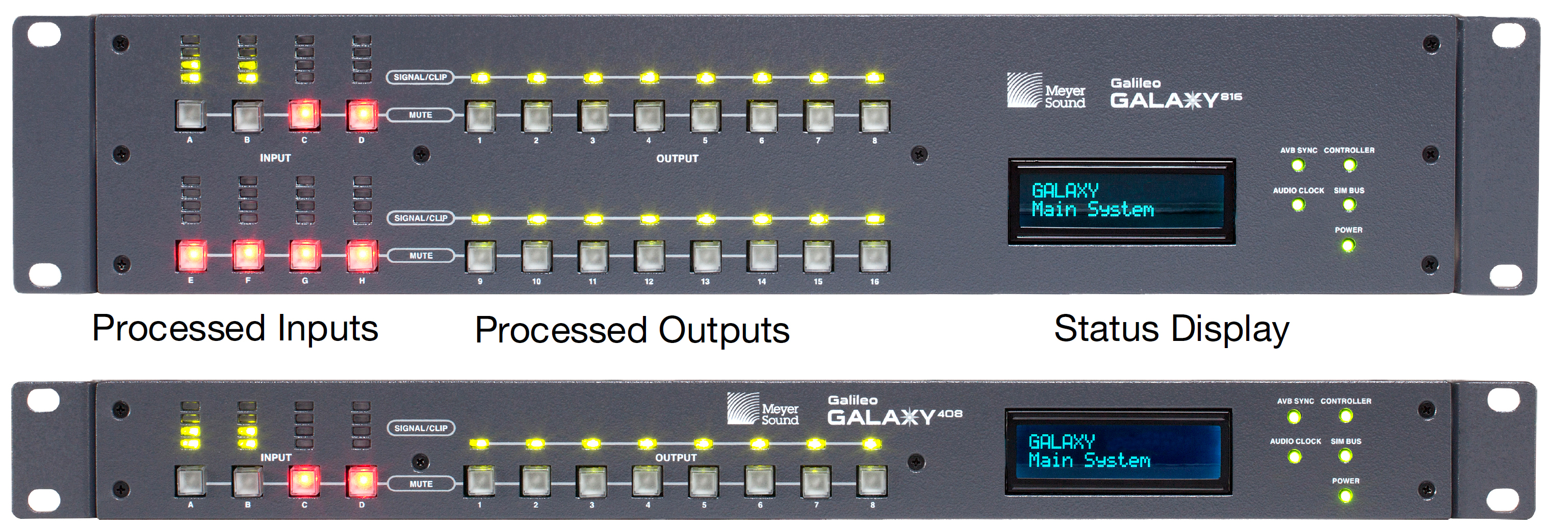
GALAXY front panels (816 and 816-AES are identical in the front, except for the name label)
The GALAXY front panel is divided into three sections:
Processed inputs
Processed outputs
Status display
Front panel processed inputs section
The GALAXY processor front panel processed inputs section is on the left side, as shown in the figure below, and consists of input level meters and input mute buttons.
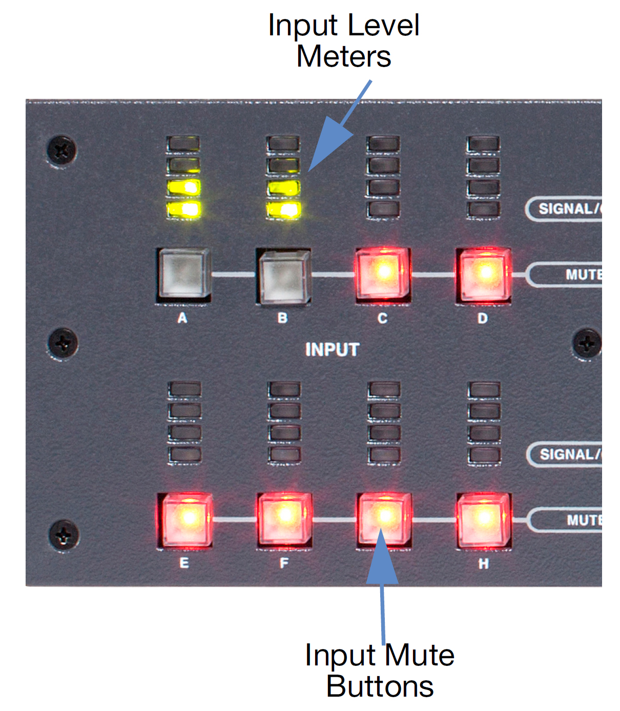
GALAXY processor front panel processed inputs section
Input level meters: Four-segment LED ladders represent the level for each input channel. The green LED range begins at approximately -80 dB below clipping. The yellow LED range lights a few dB below clipping. The top LED turns red as the input signal level reaches full-scale digital (0 dBFS). In Compass (Settings > Input and Output), the Voltage Range may be set for all input and output channels to either +16 dBu (4.89 V rms) or +26 dBu (15.5 V rms); this selection determines the clipping levels.
Note
The default input voltage range is +26 dBu.
Input mute buttons: Each input channel has a mute button. Toggling an input mute button in Compass also toggles this mute button.
Front panel processed outputs section
The GALAXY processor front panel processed outputs section is in the middle, as shown in the figure below, and consists of output signal/clip LEDs and output mute buttons.

GALAXY processor front panel processed outputs section
Signal / clip LEDs: Output level is indicated by one multi-color LED for each output channel. The LED turns green to indicate output levels from -85 dB to -5 dB below clipping. The LED glows brighter as the signal level increases. The LED turns amber to indicate levels from -5 dB to just below the clipping level. The LED turns red as the output signal level reaches full-scale digital (0 dBFS). In Compass (Settings > Input and Output), the Voltage Range for all input and output channels can be set to either +16 dBu (4.89 V rms) or +26 dBu (15.5 V rms); this setting determines the clipping levels.
Note
The default output voltage range is +26 dBu.
Output mute buttons: Each output channel has a mute button. Toggling an output mute button in Compass also toggles this mute button.
Front panel status display section
The GALAXY processor front panel status display is on the right side, as shown in the figure below, of the enclosure and includes the front panel display as well as informational LEDs.
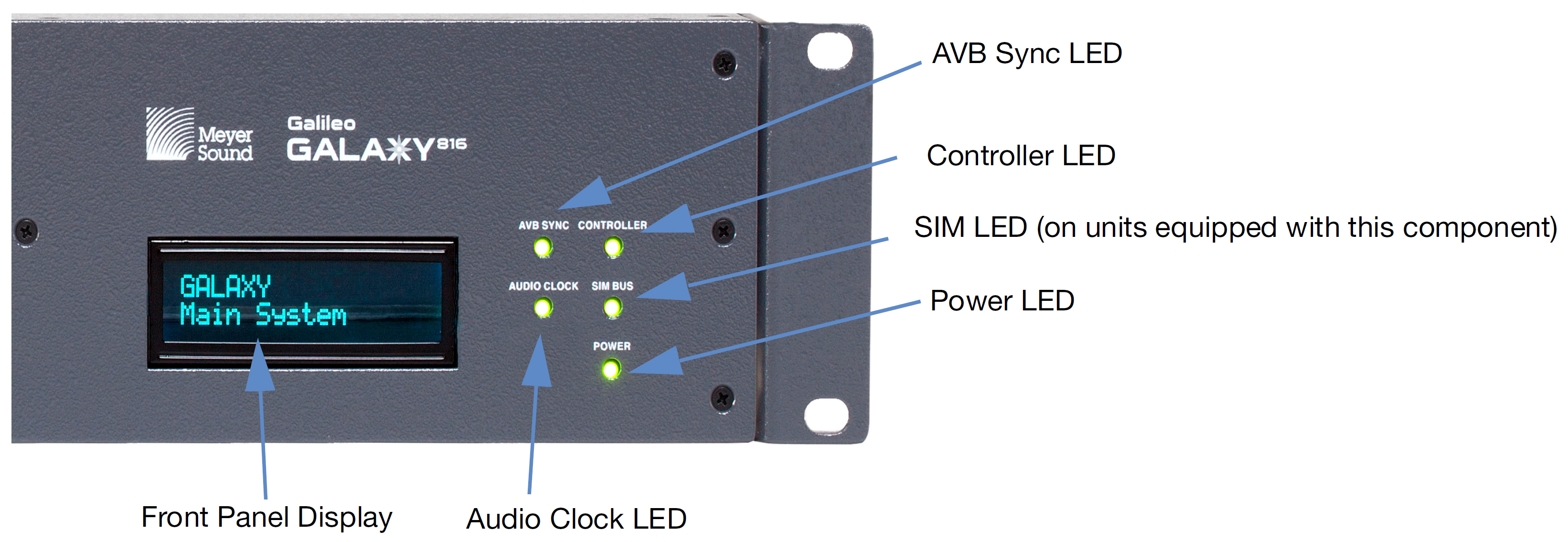
GALAXY processor front panel display
Front panel display: The front panel display provides the device name, current snapshot, device identity indicator, and other critical device notifications available on the GALAXY. Use the Front Panel Display Control in Compass to adjust the brightness and color.
Controller LED: Indicates activity when the GALAXY is connected to a client computer running the Compass control software.
SIM LED (on units equipped with this component): Indicates if the GALAXY is connected to a SIM audio analyzer.
Note
The GALAXY SIM Address must be set to a number in the range 0–14 (default is 10) in the SIM tab in Compass. It will then be available in the Switcher section of SIM under tabs 0–14, and can be configured to perform audio measurements.
Power LED: When lit, this LED indicates the GALAXY DC power supply is operating properly.
AVB sync LED: When lit, the LED indicates the GALAXY AVB media clock is locked.
Audio clock LED: When lit, the LED indicates the selected system clock (AVB, AES, or Internal) is locked.
GALAXY processor rear panels
The GALAXY 816 processor, the GALAXY 408 processor, and the GALAXY 816-AES3 processor have different rear panel connectors.
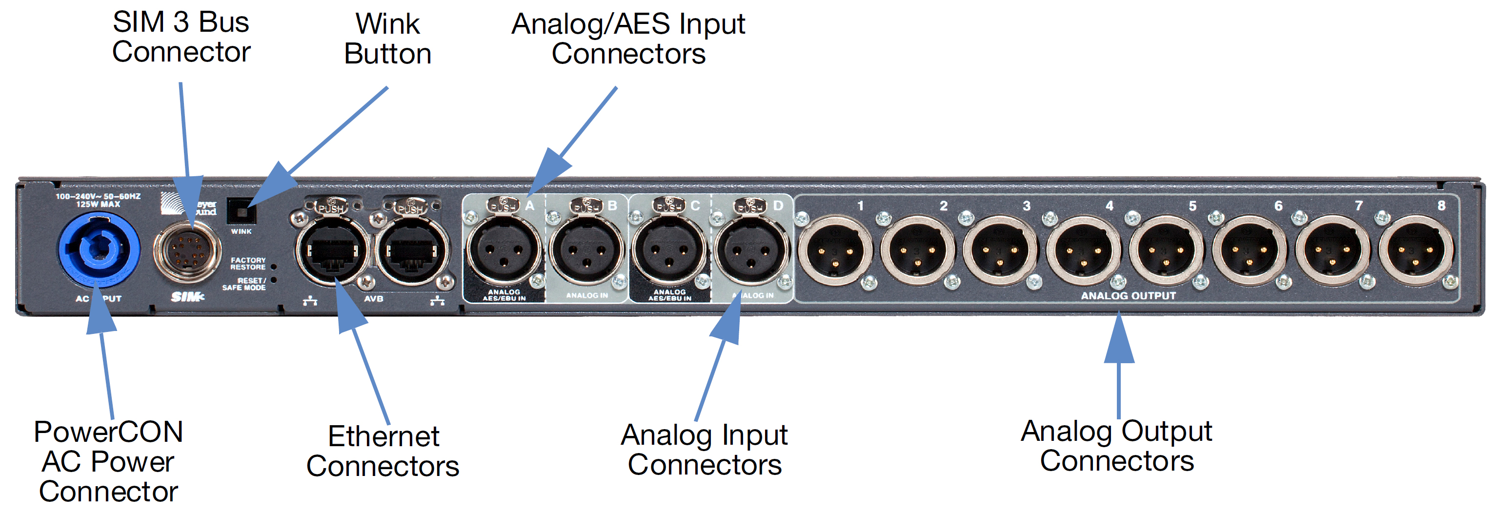
GALAXY 816 processor rear panel connectors
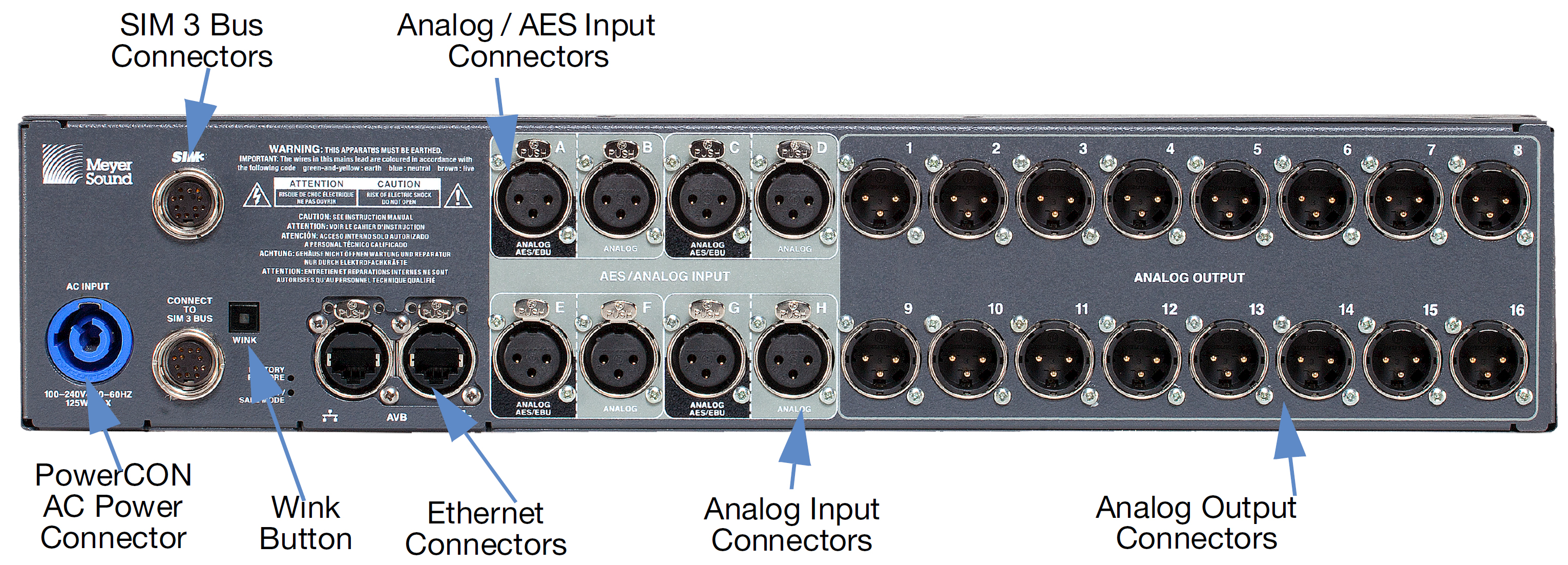
GALAXY 816 processor rear panel
The GALAXY 816 processor rear panel provides the following connectors:
PowerCON AC power connector: This locking connector mates with the provided AC power cable.
Caution
Make sure the AC power cable has the appropriate power plug on the other end for the area in which you will operate the GALAXY processor.
Note
The GALAXY processor incorporates Meyer Sound’s Intelligent AC power supply, which automatically adjusts to any line voltage worldwide, and provides soft turn-on and transient protection.
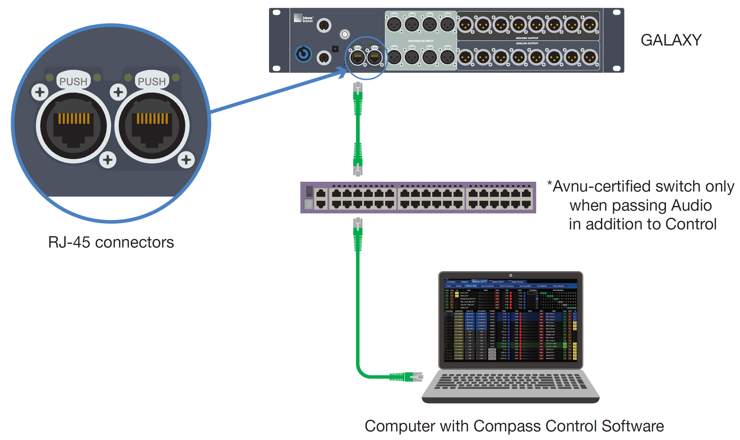
Ethernet connector: The two RJ-45 connectors can be used to attach the GALAXY processor to an AVB network to send audio signals through time-sensitive networks, and allow it to be controlled by Compass and/or Compass Go. Use a Gigabit Ethernet network cable (CAT5e or better). All primary network connections should be made to AVB port 1 on GALAXY processors. All secondary connections should be made to AVB port 2.
Analog / AES3 input connectors (A, C, E, G): Four XLR-3F input connectors accept either a standard line-level analog signal or an AES two-channel digital signal. In Compass (Settings > Input and Output), these inputs can be set to Analog, AES3 Left, or AES3 Right. Input Connectors B, D, F, and H can only be used as analog inputs. The GALAXY processor supports standard AES3 digital audio signals at discrete sample rates in the range of 20–216 kHz (see Input sample rates ).
Analog input connectors (B, D, F, H): Four XLR-3F input connectors accept standard line-level audio only. These inputs are typically paired with their corresponding input pairs (A, C, E, G) to receive two-channel audio signals. The analog-only inputs are disabled when their input pair is set to AES mode (i.e., when input A is set to AES mode, input B is disabled).
Analog output connectors (1–16): Sixteen XLR-3M connectors route audio to Meyer Sound self-powered loudspeakers or to amplifier channels driving passive systems.
SIM 3 Bus Connectors (for units equipped with these components): Connects to the SIM audio analyzer so the GALAXY’s inputs and outputs can be used as measurement points. A second SIM 3 bus port is provided to loop to additional GALAXY processors or to a SIM-3088 Line Switcher.
Wink Button: Pressing the Wink button on the rear of a GALAXY processor will cause the device to enter the Identify Mode, a bidirectional processor identification feature that helps users locate processors in multi-processor configurations. The front panel will flash, and Compass will show an indication on both the GALAXY processor’s Inventory tab and the Settings > Network tab of each processor (Settings tab). To exit Identify Mode, push the Wink button on the processor again or click on the Identify button on the Network tab in Compass.
GALAXY 408 processor rear panel connectors
GALAXY 408 Processor Rear Panel
The GALAXY 408 processor rear panel provides the following connectors:
PowerCON AC power connector: This locking connector mates with the provided AC power cable.
Caution
Make sure the AC power cable has the appropriate power plug on the other end for the area in which you will operate the GALAXY.
Note
The GALAXY processor incorporates Meyer Sound’s Intelligent AC power supply, which automatically adjusts to any line voltage worldwide, and provides soft turn-on and transient protection.
Ethernet connector: The two RJ-45 connectors can be used to attach the GALAXY processor to an AVB network to send audio signals through time-sensitive networks, and allow it to be controlled by Compass and/or Compass Go. Use a Gigabit Ethernet network cable (CAT5e or better).
Analog /AES input connectors (A, C): Two XLR-3F input connectors accept either a standard line-level analog signal or an AES two-channel digital signal. In Compass (Settings > Input and Output), these inputs can be set to Analog, AES3 Left or AES3 Right. Input connectors B and D can only be used as analog inputs. The GALAXY processor supports standard AES3 digital audio signals at discrete sample rates in the range of 20–216 kHz (Input sample rates).
Analog input connectors (B, D): Two XLR-3F input connectors accept standard line-level audio only. These inputs are typically paired with their corresponding input pairs (A, C) to receive two-channel audio signals. The analog-only inputs are disabled when their input pair is set to AES mode (i.e., when input A is set to AES mode, input B is disabled).
Analog output connectors (1–8): Eight XLR-3M connectors route audio to Meyer Sound self-powered loudspeakers, or to amplifier channels driving passive systems.
SIM 3 bus connectors (for units equipped with these components): Connects to the SIM audio analyzer so the GALAXY’s inputs and outputs can be used as measurement points.
Wink button: Pressing the Wink button on the rear of a GALAXY processor will cause the device to enter the Identify Mode, a bidirectional processor identification feature that helps users locate processors in multi-processor configurations. The front panel will flash, and Compass will show an indication on both the GALAXY processor’s Inventory tab and the Settings>Network tab of each processor (Settings tab). To exit Identify Mode, push the Wink button on the processor again or click on the Identify button on the Network tab in Compass.
GALAXY 816-AES processor rear panel connectors
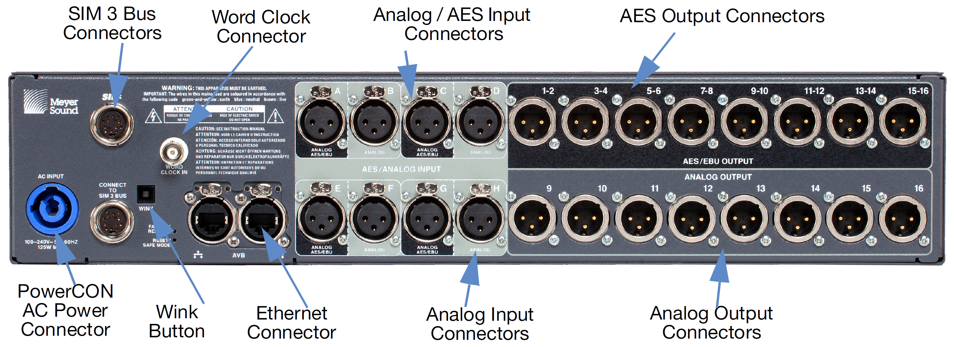
GALAXY 816-AES processor rear panel
The GALAXY 816-AES processor rear panel provides the following connectors:
PowerCON AC power connector: This locking connector mates with the provided AC power cable.
Caution
Make sure the AC power cable has the appropriate power plug on the other end for the area in which you will operate the GALAXY.
Note
The GALAXY incorporates Meyer Sound’s Intelligent AC power supply, which automatically adjusts to any line voltage worldwide, and provides soft turn-on and transient protection.
Ethernet connector: The two RJ-45 connectors can be used to attach the GALAXY processor to an AVB network to send audio signals through time-sensitive networks, and allow it to be controlled by Compass and/or Compass Go. Use a Giga-bit Ethernet network cable (CAT5e or better).
Analog / AES3 input connectors (A, C, E, G): Four XLR-3F input connectors accept either a standard line-level analog signal or an AES two-channel digital signal. In Compass (Settings > Input and Output), these inputs can be set to Analog or AES3 Left or AES3 Right. The GALAXY processor supports standard AES3 digital audio signals at discrete sample rates in the range of 20–216 kHz (see Input sample rates). Input connectors B, D, F, H can only be used as analog inputs.
Analog input connectors (B, D, F, H): Four XLR-3F input connectors accept standard line-level audio only. These inputs are typically paired with their corresponding input pairs (A, C, E, G) to receive two-channel audio signals. The analog-only inputs are disabled when their input pair is set to AES mode (i.e., when input A is set to AES mode, input B is disabled).
AES output connectors (1–16): The top row of eight XLR audio outputs for the GALAXY 816-AES3 provides 16 channels of AES3 digital outputs (two channels per output: 1–2, 3–4, etc.). Use only cables rated for AES signals to connect these outputs to the inputs of AES3 devices.
Analog output connectors (9–16): The bottom row has eight XLR-3M connectors to route audio to Meyer Sound self-powered loudspeakers or to amplifier channels driving passive systems. Any output processing applied to outputs 9–16 is mirrored in digital format on the appropriate AES3 output and on the corresponding analog output.
SIM 3 bus connectors (for units equipped with these components): Connects to the SIM audio analyzer so the GALAXY’s inputs and outputs can be used as measurement points. A second SIM 3 bus port is provided to loop an additional GALAXY or to a SIM-3088 line-level switcher.
Wink button: Pressing the Wink button on the rear of a GALAXY processor will cause the device to enter the Identify Mode, a bidirectional processor identification feature that helps users locate processors in multi-processor configurations. The front panel will flash, and Compass will show an indication on both the GALAXY processor’s Inventory tab and the Settings > Network tab of each processor (see Settings tab). To exit Identify Mode, push the Wink button on the processor again or click on the Identify button on the Network tab in Compass.
Power connector
The GALAXY uses a locking PowerCON® connector, as shown in the figure below, to provide AC voltage to the unit. Its internal switching power supply has a safety-agency-rated operating range of 100–264 V AC, 50/60 Hz.
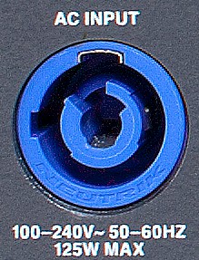
Locking PowerCON connector for AC power
Electrical safety issues!
Pay close attention to these important electrical and safety issues:
Caution
The PowerCON 20 connector should not be engaged or disengaged when under load or live. Disconnect the mains plug before disconnecting the power cord from the device.
GALAXY requires a grounded outlet. Always use a grounded outlet and plug.
 |
SIM 3 connectors (for units equipped with these components)
The GALAXY rear panel includes a bus port for direct connection to the SIM audio analyzer. The GALAXY can then act as a line switcher for the analyzer and measure across any selection of inputs and outputs without additional patching.
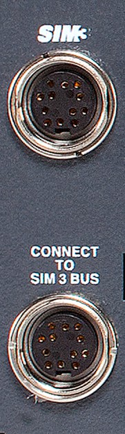 |
GALAXY processor SIM 3 connectors: Connection to SIM and/or looping to other GALAXY processors (second looping connector not available on the GALAXY 408 processor)
The default bus address for the GALAXY processor is 10 and the available range is 0–14. The bus address is changed in Compass, (Settings > SIM). The GALAXY processor to SIM connection is auto-detected. The connection is indicated in SIM, in Compass, and with the SIM Bus LED on the GALAXY processor front panel.
A second SIM Bus connector is included on the GALAXY 816 processor and the GALAXY 816-AES processor rear panels. It can be used to connect to additional GALAXY processors or SIM-3088 Line Switchers.
Note
The GALAXY 408 processor does not have a looping SIM bus connector.
Client computer connection
The GALAXY’s RJ-45 port connects to a standard computer Ethernet port with Gigabit-capable (CAT5e or better) network cables. A Mac or Windows-based computer running Compass Control Software uses an Ethernet connection to control the unit remotely. Bi-directional communication between the GALAXY processor and Compass allows the user to change settings on either device and stay in sync.
To establish a connection between a single GALAXY processor and a computer, do the following:
Download the latest version of Compass Control software from the Meyer Sound website: meyersound.com/product/compass/#software
There is a registration procedure for first-time website users.
Install the Compass Control Software on a Mac or Windows-based computer.
Connect both the GALAXY processor and the Computer with Compass Control Software installed to the network switch.
GALAXY processor and computer connected to a network switch
Apply power to the GALAXY processor by connecting the powerCON first, then the other end of the electrical cable.
Start the Compass application on the computer. The default user interface for Compass is shown below.
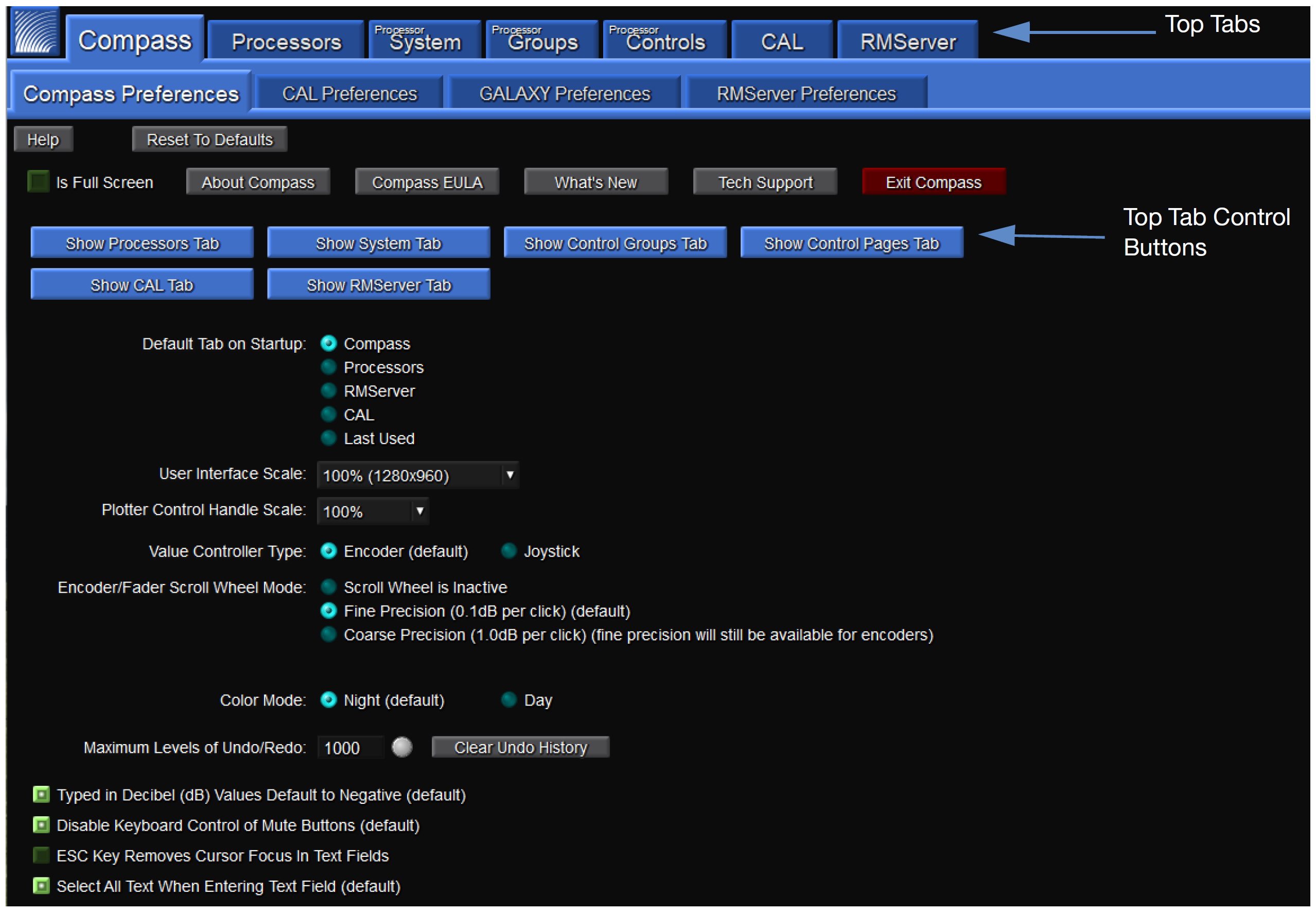
Compass default landing GUI
At this tab interface, the user can set a wide variety of preferences, including which tabs to show along the top of the Compass interface. Preferences for GALAXY processor may also be set at this level (see Setting preferences).
Make sure the Show Processors tab is selected. It will be blue when selected, and gray when deselected.
Click Processors, which then displays the Inventory tab. Click Find Devices to list the available GALAXY processors if they have not already been auto-discovered. The GALAXY processor connected in step 2 should automatically be listed. If it is not listed, verify that the switch is properly configured and all cabling is correct.
Click Connect for each of the processors to establish the client/server connection.
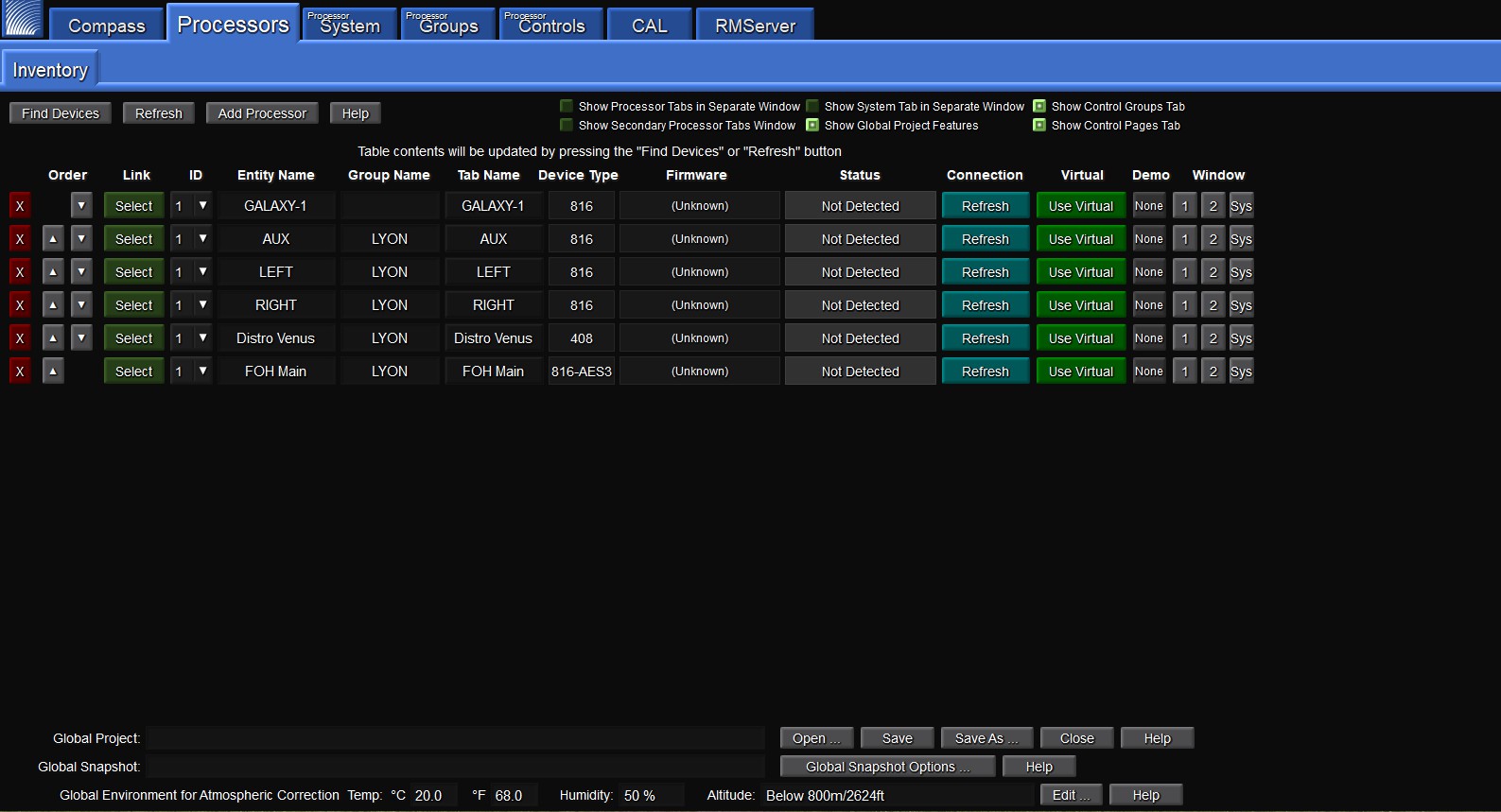
Processor tab landing window
Note
The client/server connection between GALAXY processors does not require setting IP Addresses. Compass uses IPv6 to connect to the processors. If the switches are properly configured and the cabling is correctly routed, Compass will automatically connect to the GALAXY processors.
If IPv6 addressing is unavailable, the GALAXY processors will default to IPv4 addresses as an alternate configuration method. If using a third-party controller that requires IPv4, GALAXY processors can be assigned IPv4 addresses. If assigning IPv4 addresses to a GALAXY processor, the Port 1 address and the Port 2 address cannot be the same.
GALAXY processors in a network configuration
The GALAXY processor includes two network ports for both AVB and control connections. Either port can be used to make single connections to a network. These ports take advantage of multiple industry-standard networking protocols enabling automatic fail-over. For more information about how to make AVB connections between devices, see the User Guide — Managing AVB Networks.