Power Requirements
Self-powered and compact, UPM-1P and UPM-2P loudspeakers combine advanced technology with equally advanced power capabilities. Understanding power distribution, voltage, and current requirements, as well as electrical safety issues, is critical to the safe operation of the loudspeakers.
AC Power
UPM-1P and UPM-2P loudspeakers use a PowerCon® three-pole AC mains system with locking connectors to prevent accidental disconnection. They may also be daisy-chained by using the grey connector (Figure 1.1) to loop units together. The blue connector serves as the power input; to loop additional units, simply attach a cable from the grey connector of the first loudspeaker system to the blue connector of the second, and so on. One cablemount loop-out grey connector is shipped with the unit.
 |
You can daisy-chain UPM-1P and UPM-2P loudspeakers using the grey connector
Caution
Do not loop more than four UPM-1P or UPM-2P loudspeakers from the loop out connector when driven at 115 volts and not more than eight when driven at 230 volts.
Ensure that you select the correct power plug for the AC power in the area in which you use your loudspeaker.
The power supply suppresses high voltage transients up to several kilovolts and also filters EMI (radio frequencies and noise present) on the incoming AC voltage. The UPM- 1P can withstand continuous voltages up to 264 volts and allow any combination of voltage to GND (that is neutral-line-ground or line-line-ground).
Caution
Continuous voltages higher than 265 volts may damage your UPM-1P or UPM-2P loudspeaker.
Voltage Selection
Two versions of both the UPM-1P and UPM-2P loudspeakers are available: a switchable 115/230-volt and a non-switchable 100-volt version. The non-switchable 100-volt version will operate properly when receiving between 87 and 113 volts; the switchable version requires you to check the voltage switch and set it to either 115 or 230 volts. When set to 115 volts, the UPM-1P and UPM-2P will operate properly when the AC remains within the range of 105 to 130 volts. If set to 230 volts, the unit operates safely and without audio discontinuity within the range of 210 to 264 volts. Operating outside these ranges or with the voltage switch set improperly could damage the unit.
Caution
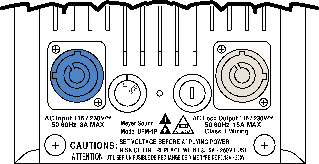
To avoid damage to the unit, check the AC voltage selector switch (shown in the figure below) on the user panel before plugging in the unit and applying power. Set the switch to local AC voltage. Always unplug the power cord before changing the voltage selector switch.
|
Rear panel AC inlet and voltage selector switch
After applying AC power, the system is muted while the circuitry charges up and stabilizes. After two seconds, the following occurs:
The main power supply slowly ramps on.
The green On/Temp LED on the user panel lights up, indicating that the system is enabled and ready to pass audio signals.
Caution
If the On/Temp LED does not illuminate or the system does not respond to audio input after 10 seconds, remove AC power immediately. Verify that the voltage is within the proper range. If the problem persists, please contact Meyer Sound or an authorized service center.
If voltage drops below the low boundary of its safe operating range (brownout), the UPM-1P or UPM-2P loudspeakers use stored energy to continue functioning briefly, and shut down only if voltage does not rise above the low boundary before storage circuits are depleted.
How long the loudspeaker will continue to function during brownout depends upon the amount of voltage drop and the audio source level during the drop.
If the voltage increases above the upper boundary of either range, the power supply may be damaged.
Note
It is recommended that the supply be operated in its rated voltage window at least a few volts away from the turn on/off points. This ensures that that AC voltage variations from the service entry – or peak voltage drops due to cable runs – do not cause the amplifier to cycle on and off or cause damage to the power supply.
Current Requirements
The UPM-1P and UPM-2P loudspeakers require approximately 3 amps rms max at 115 volts AC for proper operation. This allows up to five loudspeakers to be powered from one 15-amp breaker.
The UPM-1P and UPM-2P loudspeakers present a dynamic load to the AC mains, which causes the amount of current to fluctuate between quiet and loud operating levels. Since different cables and circuit breakers heat up at varying rates, it is essential to understand the types of current ratings and how they correspond to circuit breaker and cable specifications.
The maximum long-term continuous current is the maximum rms current during a period of at least ten seconds. It is used to calculate the temperature increase in cables, in order to select a cable size and gauge that conforms to electrical code standards. It is also used to select the rating for slow-reacting thermal breakers.
The burst current is the maximum rms current during a period of approximately one second, used to select the rating of most magnetic breakers and to calculate the peak voltage drop in long AC cables according to the formula:
V pk (drop)= I pk x R (cable total)
The ultimate short-term peak current is used to select the rating of magnetic breakers.
Use the Current Ratings for UPM-1P and UPM-2P table below as a guide when selecting cable gauge size and circuit breaker ratings for your operating voltage.
Current Draw | 115 V AC | 230 V AC | 100 V AC |
|---|---|---|---|
Max. long-term continuous | 1 A rms | 0.5 A rms | 1.2 A rms |
Burst current | 1.3 A rms | 0.65 A rms | 1.5 A rms |
Ultimate short-term peak | 2.9 A pk | 2 A pk | 3.3 A pk |
Idle current | 0.13 A rms | 0.065 A rms | 0.15 A rms |
Note
For best performance, the AC cable voltage drop should not exceed 10 volts, or 10 percent at 115 volts and 5 percent at 230 volts. Make sure that even with the AC voltage drop the AC voltage always stays in the operating window.
The minimum electrical service amperage required by UPM-1P and UPM-2P systems is the sum of each loudspeaker’s maximum continuous rms current. An additional 30 percent above the minimum amperage is recommended to prevent peak voltage drops at the service entry.
Caution
In the unlikely event that the fuse trips, always replace a fuse with the same rating and type of fuse. The UPM-1P and UPM-2P loudspeakers use a quick-acting 3.15-amp current, 250 volts low breaking capacity fuse.
Power Connector Wiring
The UPM-1P and UPM-2P loudspeakers require a grounded outlet. It is very important that the system be properly grounded in order to operate safely and properly. Use the AC cable wiring diagram shown below to create international or special-purpose power connectors.

AC cable color code
If the colors referred to in the figure above don’t correspond to the terminals in your plug, use the following guidelines:
Connect the blue wire to the terminal marked with an N or colored black.
Connect the brown wire to the terminal marked with an L or colored red.
Connect the green and yellow wire to the terminal marked with an E, G, or the protective earth ground symbol:
 .
.
Electrical Safety Issues
Pay close attention to these important electrical and safety issues.

Caution
The UPM-1P and UPM-2P require a ground connection. Always use a grounded outlet and plug. Do not use a ground-lifting adapter or cut the AC cable ground pin.

Caution
Keep all liquids away from the UPM-1P and UPM-2P to avoid hazards from electrical shock.
Do not operate the unit with worn or frayed cables; replace them immediately.